EP3775846B1 - Optische sensorvorrichtung für flüssige substanzen - Google Patents
Optische sensorvorrichtung für flüssige substanzen Download PDFInfo
- Publication number
- EP3775846B1 EP3775846B1 EP19721135.2A EP19721135A EP3775846B1 EP 3775846 B1 EP3775846 B1 EP 3775846B1 EP 19721135 A EP19721135 A EP 19721135A EP 3775846 B1 EP3775846 B1 EP 3775846B1
- Authority
- EP
- European Patent Office
- Prior art keywords
- body part
- sensor device
- optical sensor
- optical
- substance
- Prior art date
- Legal status (The legal status is an assumption and is not a legal conclusion. Google has not performed a legal analysis and makes no representation as to the accuracy of the status listed.)
- Active
Links
Images







Classifications
-
- G—PHYSICS
- G01—MEASURING; TESTING
- G01N—INVESTIGATING OR ANALYSING MATERIALS BY DETERMINING THEIR CHEMICAL OR PHYSICAL PROPERTIES
- G01N21/00—Investigating or analysing materials by the use of optical means, i.e. using sub-millimetre waves, infrared, visible or ultraviolet light
- G01N21/01—Arrangements or apparatus for facilitating the optical investigation
- G01N21/03—Cuvette constructions
- G01N21/0317—High pressure cuvettes
-
- G—PHYSICS
- G01—MEASURING; TESTING
- G01N—INVESTIGATING OR ANALYSING MATERIALS BY DETERMINING THEIR CHEMICAL OR PHYSICAL PROPERTIES
- G01N21/00—Investigating or analysing materials by the use of optical means, i.e. using sub-millimetre waves, infrared, visible or ultraviolet light
- G01N21/17—Systems in which incident light is modified in accordance with the properties of the material investigated
- G01N21/41—Refractivity; Phase-affecting properties, e.g. optical path length
- G01N21/43—Refractivity; Phase-affecting properties, e.g. optical path length by measuring critical angle
-
- G—PHYSICS
- G01—MEASURING; TESTING
- G01N—INVESTIGATING OR ANALYSING MATERIALS BY DETERMINING THEIR CHEMICAL OR PHYSICAL PROPERTIES
- G01N21/00—Investigating or analysing materials by the use of optical means, i.e. using sub-millimetre waves, infrared, visible or ultraviolet light
- G01N21/17—Systems in which incident light is modified in accordance with the properties of the material investigated
- G01N21/55—Specular reflectivity
- G01N21/552—Attenuated total reflection
-
- G—PHYSICS
- G01—MEASURING; TESTING
- G01N—INVESTIGATING OR ANALYSING MATERIALS BY DETERMINING THEIR CHEMICAL OR PHYSICAL PROPERTIES
- G01N21/00—Investigating or analysing materials by the use of optical means, i.e. using sub-millimetre waves, infrared, visible or ultraviolet light
- G01N21/01—Arrangements or apparatus for facilitating the optical investigation
- G01N21/03—Cuvette constructions
- G01N2021/036—Cuvette constructions transformable, modifiable
-
- G—PHYSICS
- G01—MEASURING; TESTING
- G01N—INVESTIGATING OR ANALYSING MATERIALS BY DETERMINING THEIR CHEMICAL OR PHYSICAL PROPERTIES
- G01N21/00—Investigating or analysing materials by the use of optical means, i.e. using sub-millimetre waves, infrared, visible or ultraviolet light
- G01N21/01—Arrangements or apparatus for facilitating the optical investigation
- G01N21/03—Cuvette constructions
- G01N2021/0364—Cuvette constructions flexible, compressible
-
- G—PHYSICS
- G01—MEASURING; TESTING
- G01N—INVESTIGATING OR ANALYSING MATERIALS BY DETERMINING THEIR CHEMICAL OR PHYSICAL PROPERTIES
- G01N21/00—Investigating or analysing materials by the use of optical means, i.e. using sub-millimetre waves, infrared, visible or ultraviolet light
- G01N21/01—Arrangements or apparatus for facilitating the optical investigation
- G01N21/03—Cuvette constructions
- G01N21/05—Flow-through cuvettes
-
- G—PHYSICS
- G01—MEASURING; TESTING
- G01N—INVESTIGATING OR ANALYSING MATERIALS BY DETERMINING THEIR CHEMICAL OR PHYSICAL PROPERTIES
- G01N2201/00—Features of devices classified in G01N21/00
- G01N2201/02—Mechanical
- G01N2201/022—Casings
Definitions
- the present invention relates to sensor devices of an optical type, used for detecting one or more characteristics of a fluid substance that is present in a generic container or duct, preferably of a vehicle.
- the invention finds preferred application in the field of optical sensors for detection of a qualitative type, for example for detecting the concentration of a liquid solution or for detecting the presence of possible impurities in a liquid substance.
- sensors for detecting characteristics such as the level, temperature, and quality.
- a typical example is represented by tanks or ducts belonging to exhaust-gas emission systems of some types of motor vehicles, conceived for the purposes of reduction of release of nitrogen oxides (NO x ) into the atmosphere.
- NO x nitrogen oxides
- a system that is particularly widespread for this purpose is based upon the process known as SCR ( Selective Catalytic Reduction ) , which enables reduction of the nitrogen oxides of the gases by means of injection of a reducing liquid substance into the exhaust line.
- SCR Selective Catalytic Reduction
- These treatment systems presuppose that the reducing agent is dosed and injected into the exhaust-gas flow in order to convert nitrogen oxide into nitrogen (N 2 ) and water (H 2 O).
- the reducing substance is typically constituted by a solution of water and urea.
- sensor devices of various types have been proposed, amongst which of particular interest - for the purposes of the present invention - are the devices of an electro-optical or opto-electronic type, which include in general at least one emitter and at least one receiver of light radiation.
- the emitter directs the radiation through a prism or similar optical body, having a surface in contact with the fluid substance.
- a part of the radiation is refracted into the substance, and a part is reflected, where the latter part is detected by the receiver.
- the reflected part of radiation is considered directly proportional to the refractive index of the fluid substance, which makes it possible to determine whether the substance in question is water or a solution of urea, and to determine the concentration of this solution.
- the devices of the type referred to operate in conditions of very low temperature: consider, for example, the case of a motor vehicle that remains exposed to temperatures lower than 0°C. It may hence occasionally happen that the fluid substance being measured freezes, thus increasing in volume. Freezing of the fluid substance does not in general entail particular risks of failure of the device both because its mechanical structure is in general strong and because its sensitive optical part, i.e., the emitter and the receiver, is in any case in a position isolated from the substance.
- the increase in volume due to freezing of the fluid substance may occasionally lead to permanent deformation or displacement or failure of the surfaces of the optical prism, and in particular of its surface at the solid-fluid interface, or of one of the surfaces where the radiation enters the prism or exits therefrom, in particular when the prism or the body part of the device that integrates it is made of a plastic material or a brittle material. Similar problems may arise in the case of excessive increase in the pressure of the substance.
- JP 2014 102217 A discloses a RIfS measurement system (Reflectometric Interference Spectroscopy) using interference color change of an optical thin film as a means to detect the bond between biomolecules and organic polymers, and comprising temperature control means and pressure control means.
- RIfS measurement system Reflectometric Interference Spectroscopy
- US 5773825 A discloses an ATR device (Attenuated Total Reflectance) used to cause measurable absorbance of radiation by a sample, including a sample-contacting element which is infrared transparent and which is resistant to corrosion, and a supporting element for the sample-contacting element which is infrared transparent and which presses against the inner surface of the sample-contacting element.
- ATR device Attenuated Total Reflectance
- US 5703366 A discloses an optical analytical system for FTIR analysis (Fourier Transform Infrared Spectroscopy), having a source of infrared energy, an infrared detector system, and a crystal assembly comprising a first crystal member having at least one circumferential focusing surface, and a crystal disc.
- FTIR analysis Frier Transform Infrared Spectroscopy
- JP H02 98654 A discloses a detector of mixing rates of liquid mixtures, having a body which defines a chamber delimited at the bottom thereof by a glass interface plate, with this chamber containing a silicon oil through which a light radiation is propagated, before reaching the interface plate, the outer surface of which is in contact with the fuel sample to be analysed.
- the device has means for compensating possible shrinkage or expansion of the silicon oil in case of temperature changes, such that the optical path of the light radiation is not disturbed.
- US 2002/018200 A1 discloses a refractometer comprising an optical module arranged floatingly inside a housing structure.
- an aim of the invention is to provide a sensor device of an optical type designed to function properly and/or not to be subject to damage even in conditions of high stresses exerted by a substance being detected on parts of the sensor itself, for example due to increases in volume of the substance or to jumps in its pressure.
- references to "an embodiment” or “one embodiment” in the framework of the present description is intended to indicate that a particular configuration, structure, or characteristic described in relation to the embodiment is comprised in at least one embodiment.
- phrases such as “in an embodiment”, “in one embodiment”, “in various embodiments”, and the like that may be present in various points of this description do not necessarily refer to one and the same embodiment.
- particular conformations, structures, or characteristics defined in the framework of this description may be combined in any adequate way in one or more embodiments, even different from the ones represented.
- the reference numbers and spatial references (such as “upper”, “lower”, “top”, “bottom”, etc.) are used herein merely for convenience and hence do not define the sphere of protection or the scope of the embodiments.
- the adjective "outer”, when referring to a surface of at least part of a portion of the device described herein, is intended to designate a surface that is to face the inside of a generic container or duct, i.e., a surface in contact with the fluid substance that is being detected, whereas the adjective “inner” is meant to designate an opposite surface of said wall, i.e., a surface that is to be located on the outside of the container or duct (for example, in which a circuit or an electrical, or electronic, or opto-electronic component is at least partially located), and in any case is not in contact with the substance.
- optical radiation is meant that part of the electromagnetic spectrum that comprises radiation with a wavelength of between 100 nm and 1 mm, including ultraviolet radiation (100-400 nm), visible radiation (380-780 nm), and infrared radiation (780 nm to1 mm).
- ultraviolet radiation 100-400 nm
- visible radiation 380-780 nm
- infrared radiation 780 nm to1 mm.
- sources of optical radiation of a coherent or laser type sources of optical radiation of a non-coherent type.
- the term "material”, for example when referred to the body of an element described, and except where otherwise specified, is to be understood as indifferently indicating a single material (e.g., a plastic material) or a composition of a number of materials (e.g., a composite material or a mixture of materials).
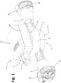
- Figure 1 designated as a whole by 1 is an optical sensor device according to possible embodiments of the invention.
- the device 1 is used for detecting one or more characteristics of a liquid additive, or reducing agent, which flows in a duct belonging to an exhaust-gas treatment system of an internal-combustion engine.
- the aforesaid treatment system may for example be of an SCR type, as explained in the introductory part of the present description, used for abatement of nitrogen-oxide emissions, for example, in motor vehicles, in particular with diesel engines.
- the aforesaid additive may hence be a solution of urea and distilled water, such as the one commercially known with the trade name AdBlue TM .
- the device 1 could be used for detecting one or more characteristics of an additive, or a generic fluid substance, or a generic mixture of substances, which flows, for example, in a duct belonging to an ADI ( Anti-Detonant Injection ) system or in a duct of a "Water-injection" system.
- ADI Anti-Detonant Injection
- the device 1 could in any case be applied to a tank, instead of to a duct, and/or be used for other purposes and/or in sectors other than the automotive one, and/or be designed for detection of at least one characteristic of a fluid substance different from a reducing agent (the ensuing definitions occasionally referring to a fluid substance or to a reducing agent can hence be understood in reference to a different fluid substance).
- a fluid substance different from a reducing agent the ensuing definitions occasionally referring to a fluid substance or to a reducing agent can hence be understood in reference to a different fluid substance.
- use of sensor devices according to the invention is particularly indicated in the case of optical detection on substances that contain water and are subject to possible freezing.
- the device 1 has a supporting structure or body 2, made up of a number of parts, at least some of which are coupled together in a fluid-tight way.
- a first body part configured for defining at least in part a space for flow or containment of the liquid substance being detected.
- the first body part 3 will also be identified as "hydraulic body” given that this body is principally designed for carrying or containing the liquid substance.
- the hydraulic body 3 has a central portion 4, which is substantially cup-shaped and from which there extend two tubular portions 5 and 6, which are here assumed as being an inlet and an outlet for the liquid substance being detected.
- the tubular parts 5 and 6 define, or have associated to them, respective connectors 5a and 6a for connection in a hydraulic circuit for the liquid substance, in particular to hydraulic attachments of respective hydraulic ducts in which the substance circulates.
- the connectors 5a and 6a each include a dowel or similar blocking member 5b and 6b, respectively, or more in general may comprise hydraulic attachments of a quick-coupling type.
- the aforesaid connectors constitute a preferential, though not essential, characteristic given that they can be obtained with any other modality, or even be omitted (e.g., envisaging a fixing via welding or gluing of the two tubular portions 5 and 6 to respective ducts of the hydraulic circuit served).
- the device 1 could be associated to a tank, in which case its hydraulic body 3 could be shaped otherwise with respect to what is exemplified in the figures, even without the aforementioned tubular portions: for instance, the hydraulic body of a device according to the invention could be mounted in the tank, or its body 3 could be defined at least in part directly by a portion of the body of the aforesaid tank.
- the hydraulic body 3 is made of a mouldable thermoplastic material, such as a polypropylene (PP), or a high-density polyethylene (HDPE), or a polysulphone (PSU), or a cyclo-olefin copolymer (COC).
- PP polypropylene
- HDPE high-density polyethylene
- PSU polysulphone
- COC cyclo-olefin copolymer
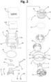
- the body 2 of the sensor device 1 includes a second part, designated by 7 in Figures 2 and 3 , designed to be coupled to the first part 3 at its cup-shaped central portion 4 or, more in general, at an area of the hydraulic body that defines at least in part the aforementioned space for containment or flow of the liquid substance.
- the body part 7 will be designated hereinafter also as "sensor body", considering that it comprises an optical arrangement; i.e., it defines and/or has associated optical-detection parts of the device 1.
- the sensor body 7 is at least partially housed within the hydraulic body 3, or at least coupled to it so that an outer surface thereof can be reached by the liquid substance.
- the body 2 of the sensor device 1 further includes a third body part 8, which is designed to be coupled to the hydraulic body 3, with the sensor body 7 set in between.
- the body part 8 will be identified hereinafter also as “casing body”, considering that it encloses within it part of the componentry of the sensor device 1.
- the casing body 8 defines or has associated a connector body 9, located in which are terminals for electrical connection of the device 1.
- a closing lid 10 is a closing lid 10.
- the cup-shaped portion 4 of the hydraulic body 3 basically defines a housing 4a, laterally delimited by a wall 4', which is preferably substantially cylindrical, with the aforesaid housing 4a that is connected in fluid communication with the tubular parts 5 and 6, each defining a corresponding internal duct 11.
- a seat 12 is defined for the body of a protection or compensation element 13, in particular a body that is at least in part elastically deformable, described in detail hereinafter, belonging to a protection arrangement of the sensor device 1.
- the seat 12 is defined at the bottom of the cup-shaped portion 4 of the body 3, or in a position generally opposite to the sensor body 7.
- the sensor body 7 has a preferably cup-shaped body, preferably having a peripheral profile mating with that of the corresponding area where it is installed, herein represented by the housing 4a, i.e., by the corresponding substantially cylindrical wall 4' of the portion 4 of the hydraulic body 3.
- the senor body 7 is shaped so as to include a detection portion of the device 1, to which there is designed to be operatively associated at least a sensitive optical part of the sensor device 1, which comprises at least one corresponding electro-optical or opto-electronic component.
- the aforesaid detection portion, mounted on the body 7, is designated as a whole by 14.
- the detection portion 14 comprises at least one bottom or interface wall 7a of the sensor body 7, having an outer lower surface, designated by 15 in Figure 3 , which is designed to delimit at least one part of the aforementioned space for containment or passage of the liquid substance.
- the detection portion 14 preferably comprises also a positioning site for the aforesaid sensitive optical part, designated by 16 in Figure 2 , which is defined at the side of the interface wall 7a that is isolated from the liquid substance, i.e., its inner surface opposite to the surface 15.
- the positioning site 16 comprises a particular conformation of the inner side or surface of the wall 7a, i.e., of a part thereof designed for propagation of light radiation.
- the detection arrangement comprises at least one emitter of optical radiation and at least one receiver of optical radiation, with the detection portion 14 that is configured so as to contribute to propagation of at least part of the optical radiation from the emitter to the receiver.
- the aforesaid optical radiation is in the frequencies of the visible, it being possible, however, for the frequency of the optical radiation to be different for the purposes of implementation of the invention: consequently, in what follows reference will be made also to rays or beams of visible light.
- the detection portion 14 is made at least in part of a material designed for propagation of light, at least by refraction and/or reflection, and both the emitter and the receiver are operatively associated to the aforesaid portion 14.
- the above material is preferably a transparent material, for example selected from cyclo-olefin copolymers (COC), or a polysulphone (PSU), or a polypropylene (PP), or a high-density polyethylene (HDPE), it possibly, however, being a glass or silica or a material containing silicon.
- the emitter and the receiver are part of a single optical module, which is mounted at the optical positioning site 16.
- Such an optical module like the detection portion 14, can be obtained and operate according to the teachings of WO 2017/149476 A , filed in the name of the present Applicant.
- the aforesaid module has a supporting and electrical-connection structure, designated as a whole by 17, which is preferably made in part of electrically insulating material and in part of electrically conductive material.
- the structure 17 of the optical module is prearranged for installation and electrical connection of a light emitter 20 and at least one light receiver 21.
- the emitter 20 may be a non-diffused Lambertian-emission light source; for example, a suitable LED and/or the receiver 21 may comprise two distinct receivers, such as photo-detectors or photo-diodes suitable for detecting the light emission generated by the emitter.
- the emitter 20 and the receiver 21 have the active parts for light emission and reception, respectively, which generally face one another, but are arranged at angles with respect to one another, preferably in such a way that the respective axes intersect.
- the relative-positioning angles for the emitter 20 and the receiver 21 substantially depend upon the type of material used for the detection portion 14, upon the type of optical radiation that it is intended to adopt, and upon the type of substance that it is to undergo detection. Preferential angles are, for example, those referred to in WO 2017/149476 , to which the reader is referred.
- an optical filter or spatial filter 20a associated to the emitter 20 is an optical filter or spatial filter 20a, in particular having the purpose of selecting or concentrating the light beam.
- the spatial filter 20a is basically a component made of plastic material not permeable to the optical radiation or light, in particular moulded, for example mounted, directly on the emitter 20 or fixed to the structure 17.
- the filter 20a is preferably configured as a cap provided with an opening in a wall thereof opposite to the light source of the emitter 20, this opening being prearranged for filtering and selecting or concentrating the light beam emitted by the emitter itself.
- Some of these terminals are designated by 17a in Figures 2-3 and 8-9 , whereas the aforementioned circuit support is designated by PCB.
- the positioning site 16 is basically constituted by a formation that rises, preferably orthogonally, from the inner side of the interface wall 7a and is designed to perform substantially functions of optical prism.
- This formation basically consists of a wall, designated by 22 in Figure 4 , which is made of the same material as the wall 7a, in particular a transparent material or a material permeable to the light or optical radiation used.
- the wall 22 defines, at its two opposite longitudinal edges, two inclined lateral faces or surfaces 23a and 23b, which are designed to face the emitter 20 and the receiver 21, respectively.
- the wall 22 is divided at least partially by an intermediate cavity so as to define two upright parts 22a and 22b, preferably substantially specular with respect to one another.
- the aforementioned intermediate cavity may advantageously receive a corresponding part of the connection and supporting structure 17 of the optical module, and the upper ends of the two upright parts 22a and 22b can be shaped so as to provide positioning appendages, which are not designated by a reference number but are clearly visible in Figure 4 , to which a blocking member is designed to be coupled, designated by 24, prearranged for withholding in position the structure 17 itself on the site 16, i.e., on the detection portion 14.
- the aforesaid appendages and the member 24 are exploited also for fixing in position an elastic element 25 for positioning the optical module, i.e., its structure 17.
- the elastic element 25, preferably made of metal material, has a central part provided with a tabbed hole (see Figures 2 and 3 ), in order to enable fixing thereof on the aforesaid appendages, as well as generally curved opposite elastic arms, designed to exert an elastic force on the structure 17 of the optical module at the areas where the emitter 20 and the receiver 21 are installed.
- the force exerted by the elastic element 25 guarantees, on the side of the emitter 20, that the spatial filter 20a bears upon the optical surface represented by the inclined surface 23a, and is correctly positioned with respect thereto.
- the force exerted on the element 24 guarantees, instead, that a purposely provided lower projection 17b of the structure 17 of the optical module bears upon the inclined surface 23b, with the receiver 21 that remains preferably facing the optical surface 23b at a slight distance therefrom.
- the emitter 20, on one side, and the two photo-detectors that provide the receiver 21, on the other side are set facing and generally parallel to the inclined surfaces 23a and 23b, respectively, of the wall 22.
- the inclination of the optical surfaces 23a and 23b is preferably calculated so that the optical radiation will traverse it in a direction as far as possible orthogonal with respect to the surfaces of entry and exit of the light, so as to minimise reflection at the air-solid and solid-air interfaces, respectively.
- the sensor device comprises at least one temperature sensor, for detecting at least one of a temperature of the liquid substance and an ambient temperature, such as the temperature of the air within the body 2 of the device itself.
- at least one temperature sensor for example of an NTC type, can be mounted on the sensor body 7 so as to be substantially in contact with the inner surface of the interface wall 7a, i.e., with the same side as that at which the site 16 is defined.
- the sensor body 7 defines a seat 30 for the detection part of a temperature sensor 31, the connection pins or terminals 31a of which are electrically connected to the circuit support PCB.
- the measurement made by the at least one temperature sensor 31 is an indirect measurement, given that the temperature sensor is not directly in contact with the liquid substance.
- the at least one temperature sensor 31 is housed within the sensor body 7, and hence in a position isolated from the substance.
- the control circuit arrangement of the device 10 - implemented on the support PCB - is prearranged for carrying out an appropriate compensation of the measurement of temperature made, which takes into account at least the presence of a wall (here the wall 7a), set between the temperature sensor 31 and the liquid substance (for example, in a memory of the circuit arrangement there may be contained corresponding corrective parameters, based upon experimental analyses).
- the casing body 8 which is preferably axially hollow, has a lower portion 8a, designed for coupling with the hydraulic body 3, and an upper housing portion 8b, to which the lid 10 is designed to be coupled.
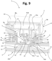
- the lower portion 8a preferably has a peripheral profile substantially corresponding to that of the central portion 4 of the hydraulic body 3, here a substantially cylindrical profile; in the example, the portion 8a is designed to be partially received within this cup-shaped portion 4, in particular surrounded at least partially by the wall 4' (see, for example, Figures 9 and 10 ), but a reversed configuration is evidently possible.
- Mutual fixing between the two body parts 8 and 3, preferably but not necessarily in a fluid-tight way, may be obtained in any suitable manner, for example by welding, or gluing, or with a threaded coupling, or with an engagement mechanism, or with a bayonet coupling, etc.
- the two bodies 8 and 3 can, instead, be coupled in a displaceable or movable way with respect to one another.
- the casing body 8 is mechanically fixed to the sensor body 7, but the bodies 7 and 8 could possibly also be made of a single piece or be co-moulded.
- the bodies 7 and 8 are configured as distinct parts, joined together by means of a coupling substantially of the snap-action type and/or of the bayonet-coupling type, possibly, however, being welded or glued together.
- reliefs 8a 1 are provided along the internal perimeter of the through cavity that traverses the lower portion 8a of the casing body 8 there are provided for this purpose reliefs 8a 1 , designed for engagement in respective seats 7b defined on the outside of the cylindrical peripheral wall of the sensor body 7, said reliefs 8a 1 and seats 7b being shaped to provide a bayonet coupling.
- a gasket made of an elastic material, in particular elastomer material, which is designated by 26, for example in Figures 2-3 .
- the aforesaid gasket 26 does not necessarily perform sealing functions and is primarily intended to enable a relatively elastic coupling between the sensor body 7 and the casing body 8, in particular when they are constrained to one another by means of a bayonet coupling or snap-action coupling, or other type of engagement mechanism designed to enable a pre-defined movement with respect to one another.
- the gasket 26, here substantially shaped like a flat ring, can in any case perform also sealing functions, as in some embodiments described hereinafter.
- the gasket 26 can be set between respective peripheral steps or reliefs defined in the peripheral parts of the lower portion 8a of the body 8 and of the body 7: in the example, defined on the inner side of the portion 8a is a step 27, whereas defined on the outer side of the peripheral wall of the body 7 is an annular relief or flange 28.
- the body 8 may be made of a material similar to the one used for formation of the body 3, preferably a mouldable thermoplastic material (as has been said, preferred materials are polypropylene, high-density polyethylene, polysulphone, or a cyclo-olefin copolymer).
- the top upper portion 8b of the casing body 8 can define a respective through cavity, which, together with the lid 10, delimits a housing for at least part of the electrical and/or electronic componentry of the sensor device.
- at least part of this componentry is mounted on an electrically insulating substrate, which provides the aforementioned support PCB.
- the support PCB is preferably made of a material suitable for producing printed circuits, such as FR4 or a similar composite material of a fibreglass type, or else a ceramic material or a polymer-based material, preferably a mouldable material.
- elements 8b 1 for positioning and/or fixing of the support PCB, such as pins or similar elements.
- the aforesaid componentry preferably includes the components for treatment and processing of signals regarding detection of at least one characteristic of the substance, such as its quality or composition, and possibly, as has been said, its temperature.
- the aforesaid componentry comprises an electronic controller, for example a microprocessor or a microcontroller, which preferably includes at least one processing and/or control logic unit, a memory circuit, and inputs and outputs, amongst which inputs of an analog/digital type.
- the aforesaid componentry then comprises elements for conditioning and/or treatment of signals regarding detection of quality and/or temperature of the liquid solution.
- terminals 9a Preferably associated to the support PCB are corresponding terminals for external electrical connection of the device 1, which are partially visible in Figures 8-10 , where they are designated by 9a. Said terminals 9a, together with the connector body 9 previously referred to, provide an interface or connector for external electrical connection of the device 1, for example to an electronic control unit of a system on-board a vehicle.
- the sensor body 7 is at least partially inserted in the housing (4a, Figure 2 ) delimited peripherally by the wall 4' of the portion 4 of the hydraulic body 3 - or in any case coupled to the body 3 in a substantially fixed position - so that the outer surface 15 of the interface wall 7a is in contact with the liquid substance; namely, it delimits at least part of the space for containment or flow of the substance.
- at least one sealing element 32 such as a sealing ring made of elastomer material.
- the element 32 is designed to create a seal of a radial type, between the peripheral wall of the sensor body 7 and an inner cylindrical wall 4b defined within the aforesaid housing (4a, Figure 2 ), i.e., a wall having diameter smaller than that of the wall 4' and concentric therewith.
- At least one of the two bodies 3 and 7 defines a respective seat for positioning of the aforesaid sealing element 32: in the example illustrated (see Figures 8-10 ), the aforesaid seat - designated by 7c - is defined in the sensor body 7, in particular at the outer side of the peripheral wall thereof, with the element 32 that on the other side is designed to operate on the inner side of the aforesaid inner cylindrical wall 4b of the body 3.
- the bodies 3 and 7 are also preferable for the bodies 3 and 7 to define respective abutments or contrast surfaces for reciprocal rest.
- the hydraulic body 3 exploits for this purpose the aforementioned inner wall 4b, upon the upper end of which the lower surface of the annular relief or flange 28 used for positioning the gasket 26 may come to bear.
- the device 1 is illustrated in an assembled condition thereof.
- the sensor body 7 is fixed to the casing body 8 (here via a bayonet coupling), and the casing body 8 is fixed to the hydraulic body 3.
- the bodies 7 and 3 are coupled in a fluid-tight way (here via the element 32) so that at least one surface of the body 7 (here the outer surface 15 of the interface wall 7a) delimits at least one part of a space for containment or passage of the substance that is to be detected.
- the optical sensor device comprises a protection arrangement, configured for preventing any possible damage or deformation (thereby including also failure), of at least part of the body 2 or of its detection portion 14, which could be caused by an increase in volume of the substance or by a thrust generated thereby, for example in the case of freezing thereof.
- the aforementioned protection arrangement comprises at least one compensation element, such as the one designated previously by 13, which has a body at least in part elastically deformable or yieldable.
- the elastically deformable body of the at least one compensation element is liable to contract, or allow itself to be at least in part compressed, in order to compensate thereby any possible increase in volume of the substance.
- the elastically deformable body of the at least one compensation element is made of an elastomer material, or an elastic and/or at least in part compressible polymer, having a bulk modulus comprised between 0.1 MPa and 1 GPa, preferably between 0.2 MPa and 100 MPa, very preferably between 0.5 MPa and 10 MPa, in particular between 1 MPa and 5 MPa.
- the material used has a hardness of between 5 Shore A and 100 Shore A, preferably between 10 Shore A and 70 Shore A, very preferably between 15 Shore A and 30 Shore A.
- the elastically deformable body may also be co-moulded with, or overmoulded on, the sensor body 7 or the hydraulic body 8.
- the body of the compensation element 13 is designed to come into contact with the liquid substance: for this purpose, as has been said, the element 13 is positioned at the corresponding seat 12 defined in the hydraulic body 3, which is located substantially in an intermediate position with respect to the ducts 11 defined by the tubular portions 5 and 6 of the body 3. More in general, according to the present invention, the aforementioned elastically deformable body delimits at least a part of the space for containment or passage of the fluid substance.
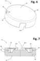
- FIG. 5-7 A possible embodiment of a compensation element 13 is illustrated schematically in Figures 5-7 .
- designated by 40 is the elastically compressible body of the element 13, which preferably comprises a bottom wall 41 and a peripheral wall 42, here having a substantially circular profile.
- the bottom wall 41 and/or the peripheral wall 42 are preferably shaped so as to define a cavity or passage P, designed to enable the presence and/or flow of the liquid substance.
- the peripheral wall 42 has two interruptions 42a, preferably but not necessarily in diametrally opposite positions.
- the bottom wall 41 is shaped so as to be thicker in its central area 41a, for the purposes clarified hereinafter, whereas at the interruptions 42a of the side wall 42 it defines inclined surfaces 41b, in form of ramps for entry and exit of the liquid substance. Also at the interruptions 42a there may be provided inclined walls, for example for fluid-dynamic reasons.
- the elastically compressible body 40 defines at least one coupling seat for a corresponding coupling part of the detection portion 14 or, more in general, the sensor body 7.
- at least part of the body 40 has a shape that is substantially complementary to, or is designed to couple with, at least part of the detection portion 14 or of the body 7.
- the areas defined as seats 43 could be configured as reliefs, and the projecting portions 7d could be configured as seats, or also have other combinations of shapes in any case designed to define areas of mutual coupling between the parts (preferably areas or shapes designed to enable a unique coupling in a substantially pre-defined position, also to prevent any risk of installation thereof in a wrong position).
- the peripheral wall 42 of the compressible body 40 may be provided with one or more seats designed to co-operate with corresponding engagement parts of the detection portion 14, or of the sensor body 7.
- two further seats 44 are defined, in each of which a corresponding radial projection of the body 7 is designed to couple, these projections being here defined on the outside of the peripheral wall of the sensor body 7, substantially at the interface wall 7a.
- These radial projections are, for example, designated by 7e in Figures 4 and 10 .
- the means for positioning and/or fixing between the compensation element 13 and the sensor body 7 preferably also determine a pre-defined positioning of the compensation element 13 itself with respect to the structure 17 of the optical module and/or the outer lower surface 15.
- means are provided (such as the means 44 and 7e) for mutual engagement between the elastically compressible body 40 and the sensor body 7, which are useful also to be able to handle the two elements coupled together, for example in the production stage; alternatively, it would be possible to envisage gluing or welding between the elastically compressible body 40 and the sensor body 7.
- the compensation element or its compressible body may be assigned a shape (e.g., via seats or reliefs) designed to co-operate with a corresponding shape or with engagement parts of the hydraulic body 3, for the purposes of mutual positioning and/or coupling or fixing; preferably, for this purpose means are provided that enable mutual assembly of the parts only in a pre-defined position (e.g., a mutual positioning or fixing of the wall 42 and/or the wall 41 of the body 40 to the seat 12).
- means are provided for mutual fixing of the compensation element, or its elastically compressible body, to the hydraulic body 3, such as engagement or welding or gluing means, useful also for enabling handling of the two elements coupled together, for example in the production stage.
- the aforesaid means for positioning and/or fixing of the compensation element, or its compressible body, to the hydraulic body 3 also determine positioning of the compensation element, or its compressible body, with respect to the sensor body 7 and/or to the structure 17 of the optical module and/or to the outer lower surface 15 of the interface wall 7a.
- At least one of the aforesaid lower projecting portions 7d of the body 7 has, on its outer side, at least one longitudinal relief 7d 1 (see Figures 3 and 10 ), which can equally be coupled in a corresponding seat 45 defined in the elastically compressible body 40.
- the aforesaid coupling of the parts 7d, and/or 7e, and/or 7d 1 to the corresponding seats 43, and/or 44, and/or 45, also prevents possible risks of rotation of the body 40 within the corresponding seat 12; or enable the aforesaid installation of the body 40 of the compensation element 13 only in the pre-defined position.
- At least one contrast relief designated by 12a for example in Figure 10 , on which a corresponding or complementary radial recess 46 ( Figures 6-7 ) is designed to be engaged, defined at the outer side of the bottom wall 42 of the body 40.
- the compensation element 13 in the assembled condition of the device 1, is positioned substantially underneath and/or in the proximity of the detection portion 14, in particular with the upper surface of the central portion 41a of the bottom wall of the body of the element 13 that faces and/or is in the proximity of the outer side 15 of the interface wall 7a of the sensor body 7, in particular with the liquid substance that can hence flow or in any case be present in the passage P that traverses the element 13 in the diametral direction.
- At least one portion of the element 13 faces the outer surface 15, at a distance therefrom, wherein the space between the two elements at issue can be occupied by the liquid substance.
- central portion 41a of the aforementioned bottom wall 41 ( Figures 5-7 ) is preferably relatively thick or in relief enables, on the one hand, reduction of the section of passage for the liquid substance precisely in the detection area represented by the interface wall 7a and, on the other hand, increase in the amount of compressible material of the body of the element 13 precisely at the aforesaid wall 7a.
- a bottom wall 41 shaped so as to bring about a reduction of the section of passage for the liquid substance, makes it possible to have a smaller thickness of frozen substance, and consequently a smaller expansion and a lower thrust in the direction of the interface wall 7a.
- a bottom wall 41 shaped so as to determine a greater thickness or an increase in the amount of compressible material enables a greater deformation and hence a greater compensation of expansion of the frozen substance and/or thrust exerted thereby, in particular in a direction opposite to that of the interface wall 7a.
- the compensation element or its compressible body is obtained at least in part (as for the stretches 41b and/or the passage P) for conveying the liquid substance into pre-defined detection area, provided in which is the protection arrangement via compensation, here substantially in a position corresponding to the interface wall 7a.
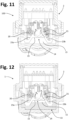
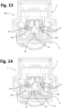
- Figures 11-14 Figures 11 and 13 representing the case of a device 100 without the protection arrangement that includes the compensation element 13, and Figures 12 and 14 illustrating, instead, the case of a device 1 according to the invention, i.e., provided with the aforesaid protection arrangement that includes the compensation element 13.
- the operating principle is based on the dependence of the refractive index of the liquid substance upon the composition or concentration of the latter.
- the measurement is hence based on the jump of refractive index between the liquid to be analysed and the solid material of which the detection portion 14 is made (i.e., the interface wall 7a and the site 16 to which the emitter 20 and the receiver 21 are associated), exploiting the principle of total internal reflection at the interface between the two media.
- the interface surface i.e., the outer surface 15 of the wall 7a in contact with the liquid
- the emitter 20 is illuminated via the emitter 20 at all the angles of interest around the critical angle, and hence with an angle of incidence greater and smaller than the critical angle.
- the photo-detectors 21 are positioned so as to receive each one part of the reflected light beam, one photo-detector being impinged upon by the high-intensity light having an angle of incidence greater than the critical angle, and the other being impinged upon by the low-intensity light on the "tail" of the reflected beam.
- Figures 11 and 12 illustrate a condition of normal operation of the devices 100 and 1, respectively, by "condition of normal operation” it being understood that the substance - designated by LS - is in its usual liquid state.
- condition of normal operation it being understood that the substance - designated by LS - is in its usual liquid state.
- the radiation beam R e emitted by the emitter 20 impinges upon the interface between the outer surface 15 and the substance LS and is then partially reflected in a beam R r towards the receiver 21, with an angle that depends upon the concentration of the substance LS itself.
- the signal at output from the receiver 21 it is possible to evaluate the quality of the liquid substance LS.
- Figures 13 and 14 illustrate, instead, the case of an increase in volume of the liquid substance LS, due for example to freezing.
- the frozen substance LS is represented (filled in) in a way different from the substance in the liquid state of Figures 11 and 12 .
- a substantially similar situation may arise in the presence of an occasional overpressure of the substance LS, for example due to a so-called ramming.
- Figure 13 shows how, in the device 100, the increase in volume of the substance LS determines a mechanical stress on the detection portion 14 such as to cause a deformation thereof, i.e., a variation of the geometrical configuration of the outer surface 15 (at the interface with the substance LS) and/or of the inclined optical surfaces 23a and/or 23b. It should be noted that the degree of deformation is deliberately exaggerated in Figure 13 , in order to bring out the phenomenon more clearly.
- the increase in volume of the liquid substance LS can be "relieved" in the opposite direction with respect to the interface surface 15; i.e., it is absorbed by the compensation element 13, which undergoes compression downwards.
- the detection portion 14 is not stressed mechanically, thereby safeguarding its geometrical integrity, and there hence do not occur variations of the angles of the rays R e and R r with respect to the case illustrated in Figure 12 (obviously, except for variations in concentration of the substance LS).
- the body 40 of the compensation element 13 may again elastically assume its own initial configuration, as illustrated in Figure 12 , thus restoring the protection function.
- the detection portion 14 will no longer be subjected to the aforesaid mechanical stress.
- the mechanical stress induced by the increase in volume of the substance could have led to overstepping of the threshold of elastic behaviour of the material of the sensor body (e.g., reaching a threshold of plastic deformation or yielding of the material); i.e., it could have produced permanent deformation: in this eventuality, the detection portion 14 and/or at least part of the interface wall 7a might not assume again its original geometrical configuration.
- the optical sensor device 1 comprises at least two compensation members, each having an elastically deformable and/or at least partially compressible body.
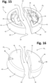
- Figures 15 and 16 are schematic illustrations of a possible embodiment of two compensation elements, designated by 13 1 and 13 2 , which can be used in a device according to the invention.
- each body 40 has a bottom wall 41 and a peripheral wall of its own, which here includes an arched wall portion 42 radiused at its ends by a longitudinal wall portion 42'.
- each body 40 may define one or more seats equivalent to those designated by 43, 44, 45, and 46 with reference to Figures 5-7 , or may define different and/or further positioning and/or fixing means.
- the elements 13 1 and 13 2 are sized, in particular in the radial direction of the corresponding arched wall portion 42, so that they can both be housed within the seat 12 provided in the hydraulic body 3, with the longitudinal wall portions 42' that are set facing one another at a certain distance: in this way, defined between the two wall portions 42' is the passage P for the liquid substance.
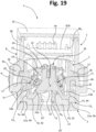
- the compensation elements 13 1 and 13 2 in the assembled condition are visible in Figures 17-19 , from which it may be noted how these elements are positioned within the seat 12, substantially so as to replace the single compensation element 13 of the previous embodiments.
- the elements 13 1 and 13 2 are positioned in the seat 12 so that the longitudinal wall portions 42' extend facing one another, preferably in the direction of the main flow of the liquid substance (i.e., the direction that connects the two tubular portions 5 and 6 of the hydraulic body 3), to define the passage P, as is clearly visible, for example, in Figure 19 .
- two distinct seats could be provided, one for each element 13 1 and 13 2 , in order to enable the aforementioned positioning.
- FIG. 20 Operation of the protection arrangement illustrated in Figures 15-19 is substantially similar to the one already described previously.
- represented schematically in Figure 20 is a condition of normal operation of the device 1, namely, a condition in which the substance LS is in its liquid state.
- the beam of radiation R e emitted by the emitter 20 hence impinges upon the interface between the outer surface 15 and the substance LS and is partially reflected in a beam R r towards the receiver 21, with an angle that depends upon the concentration of the substance LS.
- Figure 21 illustrates, instead, the case of an increase in volume of the substance LS, due for example to freezing.
- the volume of the substance LS can mainly increase in the direction transverse to the direction followed by the substance itself when it is in the liquid state (i.e., transverse to the normal direction of flow between the ducts 11); i.e., it is absorbed by the two compensation elements 13 1 and 13 2 , which undergo compression prevalently one towards the right and the other towards the left, respectively (as viewed in the figure), and in part also in the vertical direction.
- the detection portion 14 does not undergo mechanical stress, thereby safeguarding its geometrical integrity and the correctness of the angles of emission and reflection, as has been explained previously.
- the bodies 40 of the compensation elements 13 1 and 13 2 may elastically assume again their initial configurations, as illustrated in Figure 20 .
- the optical sensor device described forming the subject of the invention can, with evident structural modifications - for example, linked to the pre-defined critical angle and/or the type of its optical arrangement - be used for detecting characteristics of a fuel and/or for distinguishing mixtures of fuels, such as petrol-ethanol mixtures or diesel-biodiesel mixtures, or else for detecting possible contamination of a fuel or of a generic liquid.
- a sensor device according to the invention can find application also in apparatuses other than motor vehicles.
- the invention has been described with particular reference to a device used for detecting characteristics of a liquid substance that flows in a generic duct, but, as has been said, the principles underlying the invention can be used for providing optical sensor devices that can be applied to containers of liquid substances, such as tanks.
- the principles underlying the invention may be also applied to the case of fluid substances other than liquids (e.g., gases), which are subject to increase in volume in the case of freezing and/or in the case of pressure jumps.
- fluid substances e.g., gases
- the protection arrangement described can also be used for preventing possible increases in volume of the substance within the more extraordinarly hydraulic part of the device due to over-pressures.
Landscapes
- Physics & Mathematics (AREA)
- Health & Medical Sciences (AREA)
- Life Sciences & Earth Sciences (AREA)
- Chemical & Material Sciences (AREA)
- Analytical Chemistry (AREA)
- Biochemistry (AREA)
- General Health & Medical Sciences (AREA)
- General Physics & Mathematics (AREA)
- Immunology (AREA)
- Pathology (AREA)
- Investigating Or Analysing Materials By Optical Means (AREA)
Claims (12)
- Optische Sensorvorrichtung zum Erfassen wenigstens einer Eigenschaft eines Fluidstoffes, wobei die optische Sensorvorrichtung (1) einen Vorrichtungskörper (2) mit einem Erfassungsabschnitt (14) umfasst, mit dem ein empfindlicher optischer Teil verbunden ist, der einen Sender (20) und einen Empfänger (21) einer optischen Strahlung (Re, Rr) umfasst,wobei der Vorrichtungskörper (2) einen ersten Körperteil (3), der einen Teil eines Raums (P) zum Einschließen oder Strömen des Fluidstoffes (LS) definiert, und einen zweiten Körperteil (7), der mit dem ersten Körperteil (3) in einem Bereich des ersten Körperteils (3) gekoppelt ist, der wenigstens teilweise den Raum (P) definiert, umfasst, wobei der zweite Körperteil (7) so geformt ist, dass er den Erfassungsabschnitt (14) umfasst,wobei der Erfassungsabschnitt (14) aus einem für die optische Strahlung (Re, Rr) transparenten Material besteht und eine Grenzflächenwand (7a) mit einer ersten Fläche (23a, 23b) und einer zweiten Fläche (15) umfasst, wobei die zweite Fläche (15) dazu ausgebildet ist, mit dem Fluidstoff in Kontakt zu stehen und wenigstens einen Teil des Raums (P) zu begrenzen, und die erste Fläche (23a, 23b) dazu ausgebildet ist, vom Fluidstoff isoliert zu sein und zum Sender (20) und Empfänger (21) zu zeigen,wobei der Sender (20) und der Empfänger (21) des empfindlichen optischen Teils optisch mit der ersten Fläche (23a, 23b) der Grenzflächenwand (7a) des Erfassungsabschnitts (14) gekoppelt sind, so dass im Gebrauch die optische Strahlung (Re, Rr) wenigstens teilweise durch den Erfassungsabschnitt (14) vom Sender (20) zum Empfänger (30) verbreitet wird,wobei:- der Sender (20) und der Empfänger (21) optisch mit der ersten Fläche (23a, 23b) der Grenzflächenwand (7a) so gekoppelt sind, dass im Gebrauch die optische Strahlung (Re, Rr) vom Sender (20) die Grenzflächenwand (7a) passiert und auf eine Grenzfläche zwischen der zweiten Fläche (15) und dem Fluidstoff (LS) trifft, um dadurch zumindest teilweise reflektiert zu werden und durch die Grenzflächenwand (7a) in Richtung des Empfängers (21) in einem Winkel, der in Abhängigkeit von einer Eigenschaft des Fluidstoffes (LS) variabel ist, passiert,- der zweite Körperteil (7) mit dem ersten Körperteil (3) in einer im Wesentlichen festen und fluiddichten Position gekoppelt ist,- die optische Sensorvorrichtung ferner eine Schutzanordnung umfasst, ausgebildet zum Verhindern möglicher Verformungen des Erfassungsabschnitts(14), bewirkt durch eine Erhöhung des Volumens oder des Drucks des Fluidstoffes (LS), dadurch gekennzeichnet, dass die Schutzanordnung wenigstens ein Ausgleichselement (13; 131-132) umfasst, das dazu ausgebildet ist, mit dem Fluidstoff (LS) in Kontakt zu kommen, wobei das wenigstens eine Ausgleichselement (13; 131-132) einen Körper (40) aufweist, der wenigstens teilweise elastisch verformbar oder komprimierbar ist, um dadurch eine mögliche Zunahme des Volumens oder Drucks des Fluidstoffes (LS) auszugleichen,wobei der elastisch verformbare oder komprimierbare Körper (40) im Raum (P) zum Einschließen oder Strömen des Fluidstoffes (LS) zwischen dem ersten Körperteil (3) und dem zweiten Körperteil (7) angeordnet ist und mit dem ersten Körperteil (3) und dem zweiten Körperteil (7) gekoppelt ist, wodurch wenigstens ein Teil des Raums (P) begrenzt wird.
- Optische Sensorvorrichtung nach Anspruch 1, wobei das wenigstens eine Ausgleichselement wenigstens zwei Ausgleichselemente (131, 132) umfasst, die jeweils einen der elastisch verformbaren oder komprimierbaren Körper aufweisen.
- Optische Sensorvorrichtung nach Anspruch 1 oder Anspruch 2, wobei das wenigstens eine Ausgleichselement (13; 131-132) wenigstens einen Kopplungs- oder Positionierungssitz (43, 44, 45) für einen entsprechenden Kopplungs- oder Positionierungsteil (7d, 7e, 7di) des Erfassungsabschnitts (14) oder des zweiten Körperteils (7) definiert.
- Optische Sensorvorrichtung nach einem der Ansprüche 1 bis 3, wobei der erste Körperteil (3) einen Positionierungssitz (12) für das wenigstens eine Ausgleichselement (13; 131-132) definiert.
- Optische Sensorvorrichtung nach Anspruch 4, wobei sich der Positionierungssitz (12) in einer dem zweiten Körperteil (7) allgemein gegenüberliegenden Position befindet.
- Optische Sensorvorrichtung nach Anspruch 1, wobei:- der Erfassungsabschnitt (14) wenigstens teilweise aus einem Material besteht, das aus Cycloolefin-Copolymeren (COC) oder einem Polysulfon (PSU) oder einem Polypropylen (PP) oder einem hochdichten Polyethylen (HDPE) oder einem Glas oder Siliciumdioxid oder einem siliciumhaltigen Material ausgewählt ist; und- der elastisch verformbare oder komprimierbare Körper (40) ein Elastomermaterial oder ein elastisches und/oder komprimierbares Polymer umfasst mit:- einem Kompressionsmodul zwischen 0,1 MPa und 1 GPa; und/oder- einer Härte zwischen 5 Shore A und 100 Shore A; und/oder- einem Silikonmaterial oder einem Silikonelastomer oder einem flüssigen Silikonkautschuk oder einem fluorierten flüssigen Silikonkautschuk; und/oder- einem Polymer, das mit wenigstens einem Teil des Vorrichtungskörpers (2) mitgeformt oder auf diesem überformt ist.
- Optische Sensorvorrichtung nach einem der Ansprüche 1 bis 6, wobei der erste Körperteil (3) wenigstens einen rohrförmigen Teil (5, 6) umfasst, der mit wenigstens einem hydraulischen Steckverbinder (5a, 6a) versehen ist.
- Optische Sensorvorrichtung nach Anspruch 1, wobei der Vorrichtungskörper (2) ferner einen dritten Körperteil (8) umfasst, der mit dem ersten Körperteil (3) gekoppelt ist, wobei der zweite Körperteil (7) dazwischen liegt.
- Optische Sensorvorrichtung nach Anspruch 9, wobei der dritte Körperteil (8) mechanisch am zweiten Körperteil (7) befestigt ist oder der zweite Körperteil (7) und der dritte Körperteil (8) aus einem einzigen Stück gefertigt oder mitgeformt sind.
- Optische Sensorvorrichtung nach Anspruch 1, wobei der Sender (20) und der Empfänger (21) aktive Teile jeweils für Lichtausstrahlung und -empfang aufweisen, die im Allgemeinen zueinander zeigen, aber in Winkeln zueinander angeordnet sind, so dass sich die jeweiligen Achsen schneiden.
- Optische Sensorvorrichtung nach Anspruch 1, wobei wenigstens ein Teil des elastisch verformbaren oder komprimierbaren Körpers (40) eine Form aufweist, die im Wesentlichen ergänzend zu wenigstens einem Teil des Erfassungsabschnitts (14) ist.
- Optische Sensoreinrichtung nach Anspruch 1, wobei wenigstens ein Abschnitt des wenigstens einen Ausgleichselements (13) zur zweiten Fläche (15) der Grenzflächenwand (7a) in einem solchen Abstand zeigt, dass der Raum zwischen dem wenigstens einen Ausgleichselement (10) und der Grenzflächenwand (7a) vom Fluidstoff (LS) zur Erfassung eingenommen werden kann.
Applications Claiming Priority (2)
| Application Number | Priority Date | Filing Date | Title |
|---|---|---|---|
| IT102018000004247A IT201800004247A1 (it) | 2018-04-05 | 2018-04-05 | Dispositivo sensore ottico per sostanze fluide |
| PCT/IB2019/052733 WO2019193517A1 (en) | 2018-04-05 | 2019-04-03 | Optical sensor device for fluid substances |
Publications (3)
| Publication Number | Publication Date |
|---|---|
| EP3775846A1 EP3775846A1 (de) | 2021-02-17 |
| EP3775846B1 true EP3775846B1 (de) | 2024-11-13 |
| EP3775846C0 EP3775846C0 (de) | 2024-11-13 |
Family
ID=62751409
Family Applications (1)
| Application Number | Title | Priority Date | Filing Date |
|---|---|---|---|
| EP19721135.2A Active EP3775846B1 (de) | 2018-04-05 | 2019-04-03 | Optische sensorvorrichtung für flüssige substanzen |
Country Status (7)
| Country | Link |
|---|---|
| US (1) | US11835453B2 (de) |
| EP (1) | EP3775846B1 (de) |
| JP (1) | JP7304883B2 (de) |
| KR (1) | KR102720830B1 (de) |
| CN (1) | CN112513614B (de) |
| IT (1) | IT201800004247A1 (de) |
| WO (1) | WO2019193517A1 (de) |
Families Citing this family (3)
| Publication number | Priority date | Publication date | Assignee | Title |
|---|---|---|---|---|
| US20220349829A1 (en) * | 2021-04-29 | 2022-11-03 | Custom Sensors & Technology | Sensor and flow cell |
| CN115808508B (zh) * | 2023-02-01 | 2023-05-12 | 武汉鑫威源电子科技有限公司 | 一种ICP刻蚀对GaN材料表面损伤检测装置 |
| CN119915738B (zh) * | 2025-04-02 | 2025-08-19 | 上海逐典生物科技有限公司 | 一种生物试验用酶标仪 |
Family Cites Families (13)
| Publication number | Priority date | Publication date | Assignee | Title |
|---|---|---|---|---|
| JPH0298654A (ja) * | 1988-10-06 | 1990-04-11 | Ngk Spark Plug Co Ltd | 混合液体の液体混合比検出器 |
| US5552604A (en) * | 1994-05-13 | 1996-09-03 | Donald W. Sting | Optical sensing with crystal assembly sensing tip |
| US5773825A (en) * | 1995-09-22 | 1998-06-30 | Axiom Analytical, Inc. | Bi-layer attenuated total reflectance device providing optimized absorbance linearity |
| US5917180A (en) * | 1997-07-16 | 1999-06-29 | Canadian Space Agency | Pressure sensor based on illumination of a deformable integrating cavity |
| FI108259B (fi) * | 1998-01-30 | 2001-12-14 | Janesko Oy | Refraktometri |
| FI113566B (fi) * | 2000-08-01 | 2004-05-14 | Janesko Oy | Refraktometri |
| EP1482298A1 (de) * | 2003-05-26 | 2004-12-01 | Sensorix | Einrichtung zur kontinuierlichen Bestimmung einer Substanz |
| WO2009090585A1 (en) * | 2008-01-14 | 2009-07-23 | Koninklijke Philips Electronics N.V. | Fluid lens with pressure release system |
| IT1391187B1 (it) * | 2008-08-01 | 2011-11-18 | Eltek Spa | Dispositivo sensore di pressione |
| JP6121400B2 (ja) | 2011-04-29 | 2017-04-26 | セブンス センス バイオシステムズ,インコーポレーテッド | 流体の送達および/または受け取り |
| JP2014102217A (ja) * | 2012-11-22 | 2014-06-05 | Konica Minolta Inc | 測定システム |
| DE102016103750B4 (de) * | 2015-12-23 | 2018-04-05 | Endress+Hauser Conducta Gmbh+Co. Kg | Sensorkappe für einen optochemischen Sensor und entsprechender optochemischer Sensor |
| ITUA20161345A1 (it) | 2016-03-04 | 2017-09-04 | Eltek Spa | Dispositivo sensore per contenitori di sostanze liquide |
-
2018
- 2018-04-05 IT IT102018000004247A patent/IT201800004247A1/it unknown
-
2019
- 2019-04-03 US US17/044,632 patent/US11835453B2/en active Active
- 2019-04-03 KR KR1020207032076A patent/KR102720830B1/ko active Active
- 2019-04-03 WO PCT/IB2019/052733 patent/WO2019193517A1/en not_active Ceased
- 2019-04-03 CN CN201980037432.0A patent/CN112513614B/zh active Active
- 2019-04-03 JP JP2020554086A patent/JP7304883B2/ja active Active
- 2019-04-03 EP EP19721135.2A patent/EP3775846B1/de active Active
Also Published As
| Publication number | Publication date |
|---|---|
| JP7304883B2 (ja) | 2023-07-07 |
| KR102720830B1 (ko) | 2024-10-22 |
| WO2019193517A1 (en) | 2019-10-10 |
| CN112513614A (zh) | 2021-03-16 |
| IT201800004247A1 (it) | 2019-10-05 |
| KR20210003142A (ko) | 2021-01-11 |
| US20210199574A1 (en) | 2021-07-01 |
| EP3775846A1 (de) | 2021-02-17 |
| JP2021520486A (ja) | 2021-08-19 |
| US11835453B2 (en) | 2023-12-05 |
| CN112513614B (zh) | 2024-12-03 |
| EP3775846C0 (de) | 2024-11-13 |
Similar Documents
| Publication | Publication Date | Title |
|---|---|---|
| EP3775846B1 (de) | Optische sensorvorrichtung für flüssige substanzen | |
| CN106706542B (zh) | 低温安全传感器组件及流体传感器 | |
| US10677725B2 (en) | Sensor device for containers of liquid substances | |
| CN102265134B (zh) | 改进的波导和相关联的汽车车载光谱仪 | |
| CN109313130B (zh) | 用于液体物质的容器的传感器装置 | |
| CA2245848C (en) | Improved fluid overfill probe | |
| US4962746A (en) | Mixing liquid ratio detector device | |
| JP3853709B2 (ja) | 管内液体検出装置における投光部と受光部との固定位置演算方法及び管内液体検出装置 | |
| JP2008286645A (ja) | 燃料性状検出装置 | |
| JP4537568B2 (ja) | 漏液センサー | |
| JP2012093232A (ja) | フォトセンサ及びレベルセンサ | |
| KR20250004626A (ko) | 광학식 가스 센서 장치 | |
| JPS62276438A (ja) | アルコ−ル混合燃料の混合比センサ | |
| JPH08247933A (ja) | 液中粒子濃度検出装置 | |
| JPH08219913A (ja) | 流体圧力センサ | |
| JPH0658875A (ja) | 液体性状検出装置 | |
| CN211085603U (zh) | 一种红外光学识别装置 | |
| JP7758379B2 (ja) | 光電式液面センサ | |
| JPH0619054Y2 (ja) | 非円形歯車式流量計 | |
| JPH04242153A (ja) | 液体の混合比センサ | |
| JPS62245139A (ja) | 燃料混合比センサ | |
| JPH0534283A (ja) | 液体の性状検出装置 | |
| IT201800006586A1 (it) | Dispositivo sensore per contenitori di sostanze liquide | |
| JPS62214333A (ja) | アルコ−ル混合燃料の混合比センサ | |
| JPH02310447A (ja) | 液体の混合比検出センサ |
Legal Events
| Date | Code | Title | Description |
|---|---|---|---|
| STAA | Information on the status of an ep patent application or granted ep patent |
Free format text: STATUS: UNKNOWN |
|
| STAA | Information on the status of an ep patent application or granted ep patent |
Free format text: STATUS: THE INTERNATIONAL PUBLICATION HAS BEEN MADE |
|
| PUAI | Public reference made under article 153(3) epc to a published international application that has entered the european phase |
Free format text: ORIGINAL CODE: 0009012 |
|
| STAA | Information on the status of an ep patent application or granted ep patent |
Free format text: STATUS: REQUEST FOR EXAMINATION WAS MADE |
|
| 17P | Request for examination filed |
Effective date: 20200921 |
|
| AK | Designated contracting states |
Kind code of ref document: A1 Designated state(s): AL AT BE BG CH CY CZ DE DK EE ES FI FR GB GR HR HU IE IS IT LI LT LU LV MC MK MT NL NO PL PT RO RS SE SI SK SM TR |
|
| AX | Request for extension of the european patent |
Extension state: BA ME |
|
| DAV | Request for validation of the european patent (deleted) | ||
| DAX | Request for extension of the european patent (deleted) | ||
| STAA | Information on the status of an ep patent application or granted ep patent |
Free format text: STATUS: EXAMINATION IS IN PROGRESS |
|
| 17Q | First examination report despatched |
Effective date: 20221111 |
|
| REG | Reference to a national code |
Ref country code: DE Ref legal event code: R079 Free format text: PREVIOUS MAIN CLASS: G01N0021030000 Ipc: G01N0021552000 Ref document number: 602019061889 Country of ref document: DE |
|
| GRAP | Despatch of communication of intention to grant a patent |
Free format text: ORIGINAL CODE: EPIDOSNIGR1 |
|
| STAA | Information on the status of an ep patent application or granted ep patent |
Free format text: STATUS: GRANT OF PATENT IS INTENDED |
|
| RIC1 | Information provided on ipc code assigned before grant |
Ipc: G01N 21/05 20060101ALN20240527BHEP Ipc: G01N 21/03 20060101ALI20240527BHEP Ipc: G01N 21/43 20060101ALI20240527BHEP Ipc: G01N 21/552 20140101AFI20240527BHEP |
|
| INTG | Intention to grant announced |
Effective date: 20240611 |
|
| GRAS | Grant fee paid |
Free format text: ORIGINAL CODE: EPIDOSNIGR3 |
|
| GRAA | (expected) grant |
Free format text: ORIGINAL CODE: 0009210 |
|
| STAA | Information on the status of an ep patent application or granted ep patent |
Free format text: STATUS: THE PATENT HAS BEEN GRANTED |
|
| AK | Designated contracting states |
Kind code of ref document: B1 Designated state(s): AL AT BE BG CH CY CZ DE DK EE ES FI FR GB GR HR HU IE IS IT LI LT LU LV MC MK MT NL NO PL PT RO RS SE SI SK SM TR |
|
| REG | Reference to a national code |
Ref country code: GB Ref legal event code: FG4D |
|
| REG | Reference to a national code |
Ref country code: CH Ref legal event code: EP |
|
| REG | Reference to a national code |
Ref country code: IE Ref legal event code: FG4D |
|
| REG | Reference to a national code |
Ref country code: DE Ref legal event code: R096 Ref document number: 602019061889 Country of ref document: DE |
|
| U01 | Request for unitary effect filed |
Effective date: 20241114 |
|
| U07 | Unitary effect registered |
Designated state(s): AT BE BG DE DK EE FI FR IT LT LU LV MT NL PT RO SE SI Effective date: 20241121 |
|
| PG25 | Lapsed in a contracting state [announced via postgrant information from national office to epo] |
Ref country code: HR Free format text: LAPSE BECAUSE OF FAILURE TO SUBMIT A TRANSLATION OF THE DESCRIPTION OR TO PAY THE FEE WITHIN THE PRESCRIBED TIME-LIMIT Effective date: 20241113 Ref country code: IS Free format text: LAPSE BECAUSE OF FAILURE TO SUBMIT A TRANSLATION OF THE DESCRIPTION OR TO PAY THE FEE WITHIN THE PRESCRIBED TIME-LIMIT Effective date: 20250313 |
|
| PG25 | Lapsed in a contracting state [announced via postgrant information from national office to epo] |
Ref country code: ES Free format text: LAPSE BECAUSE OF FAILURE TO SUBMIT A TRANSLATION OF THE DESCRIPTION OR TO PAY THE FEE WITHIN THE PRESCRIBED TIME-LIMIT Effective date: 20241113 |
|
| PG25 | Lapsed in a contracting state [announced via postgrant information from national office to epo] |
Ref country code: NO Free format text: LAPSE BECAUSE OF FAILURE TO SUBMIT A TRANSLATION OF THE DESCRIPTION OR TO PAY THE FEE WITHIN THE PRESCRIBED TIME-LIMIT Effective date: 20250213 |
|
| PG25 | Lapsed in a contracting state [announced via postgrant information from national office to epo] |
Ref country code: GR Free format text: LAPSE BECAUSE OF FAILURE TO SUBMIT A TRANSLATION OF THE DESCRIPTION OR TO PAY THE FEE WITHIN THE PRESCRIBED TIME-LIMIT Effective date: 20250214 |
|
| PG25 | Lapsed in a contracting state [announced via postgrant information from national office to epo] |
Ref country code: PL Free format text: LAPSE BECAUSE OF FAILURE TO SUBMIT A TRANSLATION OF THE DESCRIPTION OR TO PAY THE FEE WITHIN THE PRESCRIBED TIME-LIMIT Effective date: 20241113 |
|
| PG25 | Lapsed in a contracting state [announced via postgrant information from national office to epo] |
Ref country code: RS Free format text: LAPSE BECAUSE OF FAILURE TO SUBMIT A TRANSLATION OF THE DESCRIPTION OR TO PAY THE FEE WITHIN THE PRESCRIBED TIME-LIMIT Effective date: 20250213 |
|
| U20 | Renewal fee for the european patent with unitary effect paid |
Year of fee payment: 7 Effective date: 20250401 |
|
| PG25 | Lapsed in a contracting state [announced via postgrant information from national office to epo] |
Ref country code: SM Free format text: LAPSE BECAUSE OF FAILURE TO SUBMIT A TRANSLATION OF THE DESCRIPTION OR TO PAY THE FEE WITHIN THE PRESCRIBED TIME-LIMIT Effective date: 20241113 |
|
| PG25 | Lapsed in a contracting state [announced via postgrant information from national office to epo] |
Ref country code: SK Free format text: LAPSE BECAUSE OF FAILURE TO SUBMIT A TRANSLATION OF THE DESCRIPTION OR TO PAY THE FEE WITHIN THE PRESCRIBED TIME-LIMIT Effective date: 20241113 |
|
| PG25 | Lapsed in a contracting state [announced via postgrant information from national office to epo] |
Ref country code: CZ Free format text: LAPSE BECAUSE OF FAILURE TO SUBMIT A TRANSLATION OF THE DESCRIPTION OR TO PAY THE FEE WITHIN THE PRESCRIBED TIME-LIMIT Effective date: 20241113 |
|
| PLBE | No opposition filed within time limit |
Free format text: ORIGINAL CODE: 0009261 |
|
| STAA | Information on the status of an ep patent application or granted ep patent |
Free format text: STATUS: NO OPPOSITION FILED WITHIN TIME LIMIT |
|
| 26N | No opposition filed |
Effective date: 20250814 |
|
| REG | Reference to a national code |
Ref country code: CH Ref legal event code: H13 Free format text: ST27 STATUS EVENT CODE: U-0-0-H10-H13 (AS PROVIDED BY THE NATIONAL OFFICE) Effective date: 20251125 |
|
| PG25 | Lapsed in a contracting state [announced via postgrant information from national office to epo] |
Ref country code: MC Free format text: LAPSE BECAUSE OF FAILURE TO SUBMIT A TRANSLATION OF THE DESCRIPTION OR TO PAY THE FEE WITHIN THE PRESCRIBED TIME-LIMIT Effective date: 20241113 |
|
| PG25 | Lapsed in a contracting state [announced via postgrant information from national office to epo] |
Ref country code: CH Free format text: LAPSE BECAUSE OF NON-PAYMENT OF DUE FEES Effective date: 20250430 |
|
| PGFP | Annual fee paid to national office [announced via postgrant information from national office to epo] |
Ref country code: GB Payment date: 20260304 Year of fee payment: 8 |
|
| PG25 | Lapsed in a contracting state [announced via postgrant information from national office to epo] |
Ref country code: IE Free format text: LAPSE BECAUSE OF NON-PAYMENT OF DUE FEES Effective date: 20250403 |
|
| U20 | Renewal fee for the european patent with unitary effect paid |
Year of fee payment: 8 Effective date: 20260319 |