EP3775459B1 - Antriebsvorrichtung für einen verschiebbaren flügel als schiebeflügel oder verschiebbaren hebe-schiebeflügel eines fensters oder einer tür - Google Patents
Antriebsvorrichtung für einen verschiebbaren flügel als schiebeflügel oder verschiebbaren hebe-schiebeflügel eines fensters oder einer tür Download PDFInfo
- Publication number
- EP3775459B1 EP3775459B1 EP19709859.3A EP19709859A EP3775459B1 EP 3775459 B1 EP3775459 B1 EP 3775459B1 EP 19709859 A EP19709859 A EP 19709859A EP 3775459 B1 EP3775459 B1 EP 3775459B1
- Authority
- EP
- European Patent Office
- Prior art keywords
- window
- door
- casement
- housing
- threaded spindle
- Prior art date
- Legal status (The legal status is an assumption and is not a legal conclusion. Google has not performed a legal analysis and makes no representation as to the accuracy of the status listed.)
- Active
Links
- 230000005540 biological transmission Effects 0.000 claims description 6
- 238000005304 joining Methods 0.000 claims description 2
- 230000037431 insertion Effects 0.000 claims 1
- 238000003780 insertion Methods 0.000 claims 1
- 238000009434 installation Methods 0.000 description 10
- 230000008878 coupling Effects 0.000 description 6
- 238000010168 coupling process Methods 0.000 description 6
- 238000005859 coupling reaction Methods 0.000 description 6
- 238000006073 displacement reaction Methods 0.000 description 5
- 230000006378 damage Effects 0.000 description 3
- XAGFODPZIPBFFR-UHFFFAOYSA-N aluminium Chemical compound [Al] XAGFODPZIPBFFR-UHFFFAOYSA-N 0.000 description 2
- 229910052782 aluminium Inorganic materials 0.000 description 2
- 238000004512 die casting Methods 0.000 description 2
- 238000001746 injection moulding Methods 0.000 description 2
- 230000003993 interaction Effects 0.000 description 2
- 238000004519 manufacturing process Methods 0.000 description 2
- 239000007787 solid Substances 0.000 description 2
- 230000007704 transition Effects 0.000 description 2
- 238000009423 ventilation Methods 0.000 description 2
- 239000002023 wood Substances 0.000 description 2
- 208000027418 Wounds and injury Diseases 0.000 description 1
- 230000004308 accommodation Effects 0.000 description 1
- 230000006978 adaptation Effects 0.000 description 1
- 238000013459 approach Methods 0.000 description 1
- 230000008901 benefit Effects 0.000 description 1
- 230000015572 biosynthetic process Effects 0.000 description 1
- 238000010276 construction Methods 0.000 description 1
- 230000007812 deficiency Effects 0.000 description 1
- 238000005553 drilling Methods 0.000 description 1
- 230000000694 effects Effects 0.000 description 1
- 208000014674 injury Diseases 0.000 description 1
- 238000003801 milling Methods 0.000 description 1
- 230000001681 protective effect Effects 0.000 description 1
- 238000003860 storage Methods 0.000 description 1
- 230000003313 weakening effect Effects 0.000 description 1
Images

Classifications
-
- E—FIXED CONSTRUCTIONS
- E05—LOCKS; KEYS; WINDOW OR DOOR FITTINGS; SAFES
- E05F—DEVICES FOR MOVING WINGS INTO OPEN OR CLOSED POSITION; CHECKS FOR WINGS; WING FITTINGS NOT OTHERWISE PROVIDED FOR, CONCERNED WITH THE FUNCTIONING OF THE WING
- E05F15/00—Power-operated mechanisms for wings
- E05F15/60—Power-operated mechanisms for wings using electrical actuators
- E05F15/603—Power-operated mechanisms for wings using electrical actuators using rotary electromotors
- E05F15/632—Power-operated mechanisms for wings using electrical actuators using rotary electromotors for horizontally-sliding wings
- E05F15/652—Power-operated mechanisms for wings using electrical actuators using rotary electromotors for horizontally-sliding wings operated by screw-and-nut mechanisms
-
- E—FIXED CONSTRUCTIONS
- E05—LOCKS; KEYS; WINDOW OR DOOR FITTINGS; SAFES
- E05F—DEVICES FOR MOVING WINGS INTO OPEN OR CLOSED POSITION; CHECKS FOR WINGS; WING FITTINGS NOT OTHERWISE PROVIDED FOR, CONCERNED WITH THE FUNCTIONING OF THE WING
- E05F15/00—Power-operated mechanisms for wings
- E05F15/60—Power-operated mechanisms for wings using electrical actuators
- E05F15/603—Power-operated mechanisms for wings using electrical actuators using rotary electromotors
- E05F15/632—Power-operated mechanisms for wings using electrical actuators using rotary electromotors for horizontally-sliding wings
- E05F15/635—Power-operated mechanisms for wings using electrical actuators using rotary electromotors for horizontally-sliding wings operated by push-pull mechanisms, e.g. flexible or rigid rack-and-pinion arrangements
-
- E—FIXED CONSTRUCTIONS
- E05—LOCKS; KEYS; WINDOW OR DOOR FITTINGS; SAFES
- E05Y—INDEXING SCHEME RELATING TO HINGES OR OTHER SUSPENSION DEVICES FOR DOORS, WINDOWS OR WINGS AND DEVICES FOR MOVING WINGS INTO OPEN OR CLOSED POSITION, CHECKS FOR WINGS AND WING FITTINGS NOT OTHERWISE PROVIDED FOR, CONCERNED WITH THE FUNCTIONING OF THE WING
- E05Y2201/00—Constructional elements; Accessories therefore
- E05Y2201/10—Covers; Housings
-
- E—FIXED CONSTRUCTIONS
- E05—LOCKS; KEYS; WINDOW OR DOOR FITTINGS; SAFES
- E05Y—INDEXING SCHEME RELATING TO HINGES OR OTHER SUSPENSION DEVICES FOR DOORS, WINDOWS OR WINGS AND DEVICES FOR MOVING WINGS INTO OPEN OR CLOSED POSITION, CHECKS FOR WINGS AND WING FITTINGS NOT OTHERWISE PROVIDED FOR, CONCERNED WITH THE FUNCTIONING OF THE WING
- E05Y2201/00—Constructional elements; Accessories therefore
- E05Y2201/40—Motors; Magnets; Springs; Weights; Accessories therefore
- E05Y2201/404—Motors; Magnets; Springs; Weights; Accessories therefore characterised by the function
- E05Y2201/41—Motors; Magnets; Springs; Weights; Accessories therefore characterised by the function for closing
-
- E—FIXED CONSTRUCTIONS
- E05—LOCKS; KEYS; WINDOW OR DOOR FITTINGS; SAFES
- E05Y—INDEXING SCHEME RELATING TO HINGES OR OTHER SUSPENSION DEVICES FOR DOORS, WINDOWS OR WINGS AND DEVICES FOR MOVING WINGS INTO OPEN OR CLOSED POSITION, CHECKS FOR WINGS AND WING FITTINGS NOT OTHERWISE PROVIDED FOR, CONCERNED WITH THE FUNCTIONING OF THE WING
- E05Y2201/00—Constructional elements; Accessories therefore
- E05Y2201/40—Motors; Magnets; Springs; Weights; Accessories therefore
- E05Y2201/46—Magnets
-
- E—FIXED CONSTRUCTIONS
- E05—LOCKS; KEYS; WINDOW OR DOOR FITTINGS; SAFES
- E05Y—INDEXING SCHEME RELATING TO HINGES OR OTHER SUSPENSION DEVICES FOR DOORS, WINDOWS OR WINGS AND DEVICES FOR MOVING WINGS INTO OPEN OR CLOSED POSITION, CHECKS FOR WINGS AND WING FITTINGS NOT OTHERWISE PROVIDED FOR, CONCERNED WITH THE FUNCTIONING OF THE WING
- E05Y2201/00—Constructional elements; Accessories therefore
- E05Y2201/60—Suspension or transmission members; Accessories therefore
- E05Y2201/622—Suspension or transmission members elements
- E05Y2201/696—Screw mechanisms
- E05Y2201/702—Spindles; Worms
-
- E—FIXED CONSTRUCTIONS
- E05—LOCKS; KEYS; WINDOW OR DOOR FITTINGS; SAFES
- E05Y—INDEXING SCHEME RELATING TO HINGES OR OTHER SUSPENSION DEVICES FOR DOORS, WINDOWS OR WINGS AND DEVICES FOR MOVING WINGS INTO OPEN OR CLOSED POSITION, CHECKS FOR WINGS AND WING FITTINGS NOT OTHERWISE PROVIDED FOR, CONCERNED WITH THE FUNCTIONING OF THE WING
- E05Y2201/00—Constructional elements; Accessories therefore
- E05Y2201/60—Suspension or transmission members; Accessories therefore
- E05Y2201/622—Suspension or transmission members elements
- E05Y2201/71—Toothed gearing
- E05Y2201/722—Racks
-
- E—FIXED CONSTRUCTIONS
- E05—LOCKS; KEYS; WINDOW OR DOOR FITTINGS; SAFES
- E05Y—INDEXING SCHEME RELATING TO HINGES OR OTHER SUSPENSION DEVICES FOR DOORS, WINDOWS OR WINGS AND DEVICES FOR MOVING WINGS INTO OPEN OR CLOSED POSITION, CHECKS FOR WINGS AND WING FITTINGS NOT OTHERWISE PROVIDED FOR, CONCERNED WITH THE FUNCTIONING OF THE WING
- E05Y2600/00—Mounting or coupling arrangements for elements provided for in this subclass
- E05Y2600/60—Mounting or coupling members; Accessories therefore
-
- E—FIXED CONSTRUCTIONS
- E05—LOCKS; KEYS; WINDOW OR DOOR FITTINGS; SAFES
- E05Y—INDEXING SCHEME RELATING TO HINGES OR OTHER SUSPENSION DEVICES FOR DOORS, WINDOWS OR WINGS AND DEVICES FOR MOVING WINGS INTO OPEN OR CLOSED POSITION, CHECKS FOR WINGS AND WING FITTINGS NOT OTHERWISE PROVIDED FOR, CONCERNED WITH THE FUNCTIONING OF THE WING
- E05Y2800/00—Details, accessories and auxiliary operations not otherwise provided for
- E05Y2800/20—Combinations of elements
- E05Y2800/205—Combinations of elements forming a unit
-
- E—FIXED CONSTRUCTIONS
- E05—LOCKS; KEYS; WINDOW OR DOOR FITTINGS; SAFES
- E05Y—INDEXING SCHEME RELATING TO HINGES OR OTHER SUSPENSION DEVICES FOR DOORS, WINDOWS OR WINGS AND DEVICES FOR MOVING WINGS INTO OPEN OR CLOSED POSITION, CHECKS FOR WINGS AND WING FITTINGS NOT OTHERWISE PROVIDED FOR, CONCERNED WITH THE FUNCTIONING OF THE WING
- E05Y2900/00—Application of doors, windows, wings or fittings thereof
- E05Y2900/10—Application of doors, windows, wings or fittings thereof for buildings or parts thereof
- E05Y2900/13—Application of doors, windows, wings or fittings thereof for buildings or parts thereof characterised by the type of wing
- E05Y2900/132—Doors
Definitions
- the invention relates to a door or window with a displaceable sash as a sliding sash or displaceable lifting and sliding sash, a window frame in which the sash is held displaceably, and a drive device.
- drives arranged in a concealed manner are known, but these can only be integrated with great effort and in only unsuitable profile systems.
- the milling effort in the profile proves to be very high and can lead to high costs and weakening of the structure of the window or door elements.
- a sliding window or a sliding door with a window frame has become known, in which at least one sliding sash is movably held, which can be moved via a drive and coupled to the window frame via locking means, the sliding sash having four frame profiles fixed to one another.
- the drive comprises a driven drive roller around which a tensioning element fixed to the window frame is wound, with the tensioning element being guided over two deflection rollers and running into a hollow chamber of the frame profile.
- the present control device can only be reached from the guide rail via a deflection to the guide rail, which complicates the structure at high cost and requires a correspondingly large amount of space in the wing.
- the components of the control device are distributed at a great distance from one another on the guide rail, which makes assembly difficult due to individual component components.
- a passenger door designed as a sliding door or pivoting sliding door for public transport vehicles is provided with at least one door panel that can be displaced in its longitudinal direction, which is suspended in a support guide and guided in a displaceable manner.
- the support guide has a linear guide with at least one guide rail, on which a guide carriage is guided and on which the door leaf is suspended via a support arm. Due to its structural design, the support guide cannot be installed in a window or door system so that it is concealed. Furthermore, the configuration is complex to assemble and expensive to manufacture due to the large number of components.
- WO 2014/097211 A1 has become known, which has a door or window with a displaceable sash as a sliding sash or displaceable lifting and sliding sash, a window frame in which the sash is held displaceably, and a drive device, wherein the drive device for moving the sash has a drive motor arranged on the frame side with a drive motor driven thereon Includes threaded spindle, which is positively guided around a rack element arranged on the wing, wherein the drive motor and the threaded spindle are mounted as a structural unit in a housing.
- the DE 20 2005 000165 U1 a drive device in which the motor-gear unit is arranged in a receiving groove of an upper, horizontal spar of the wing and the rack element in the guide rail.
- This unit includes a bevel gear which translates rotation of the motor shaft about a horizontal axis into rotation of a shaft about a vertical axis, which shaft drives a pinion which meshes with the rack member.
- the carriage of the sliding door is designed in such a way that the upper, horizontal beam of the wing and the guide rail are spaced apart from one another in the vertical direction.
- the object of the present invention is therefore to eliminate the known deficiencies and, in contrast, provides a drive for a sliding sash as a sliding sash or lift-sliding sash for large carrying options and optimal guidance for a window or door at low cost and small installation space, which also in a simple way can also be retrofitted, adjusted and dismantled quickly, safely and precisely.
- the movable wing preferably has at least two carriages, each with rollers, in order to be displaced on a running rail in a direction parallel to the extension of the wing or along a running rail.
- an operating element with a switch is preferably provided on a vertical spar, which controls a drive device.
- the movable sash can be moved, for example, from a closed position into one in relation to a fixed window frame and a sash or door panel mounted in a fixed location.
- the sash can also be brought into a secure, shifted ventilation position or an area of a passage opening.
- the sash is supported in an advantageous manner on the bottom side having carriages on a running rail on the frame movably held.
- a control unit is provided on the window or the door.
- the control unit can also be accommodated in a wall of a building and is connected to the operating element and the drive device via control lines.
- the operating element can also control a drive arranged in the closing direction at the front on the vertical beam, which also converts locking means having on the vertical beam into a locked closed position or into an unlocked open position of the leaf.
- Manual actuation by means of an actuation handle with transmission of an actuation linkage to the locking means is also conceivable.
- the movable sash can be moved by the drive via the operating element automatically or via the manual operating handle from the closed position through a coupled connection of the operating linkage to the carriage into a raised open position in order to then to be able to be moved by the drive device.
- both actuation variants described above can also be arranged in a window or a door, which can be selected according to the requirements and resemble the character of a hybrid system. Additional drives selected for the system are additionally connected to the control lines and linked to the control unit.
- a special fitting arrangement is provided between the movable wing and the fixed window frame, namely a so-called system for sliding sashes or movable lift-and-slide sashes.
- the drive device for moving the wing includes a wing-side arranged drive motor with a threaded spindle driven thereon.
- the threaded spindle is positively guided around a toothed rack element arranged on the window frame.
- a concealed arrangement of the drive device is made possible by the fact that the drive device is mounted almost completely in the installed position of the movable wing in a recess or receiving groove of an upper, horizontal spar of the movable wing and a guide rail arranged on the frame.
- the drive motor and the threaded spindle are mounted as a structural unit in a housing.
- the rack element is almost completely encompassed by the guide rail.
- a gap in the guide rail forms an opening and thus the possibility of coupling between the sash-side components and the frame-side components of the drive device.
- the drive motor and the threaded spindle are offset vertically in height and horizontally in the longitudinal direction to the housing and thus to the recess or receiving groove of the movable wing, with the drive motor facing a base plate of the housing and thus a bottom of the recess or receiving groove and the threaded spindle from the Bottom is spaced in the direction of the rack member.
- a simple assembly and assembly of the drive components in the housing is achieved in that a locking member is provided below the drive motor on the side facing the base plate of the housing and can be clipped into a recess in the housing with a force fit.
- elastic locking projections are provided with run-in bevels on the outside of the locking member, adapted to the recess on the housing.
- the locking projections snap into the recess of the housing with slight spring force and form a detachable connection with the housing.
- the drive motor and the threaded spindle with the shaft and a carriage can be pre-assembled as an integral unit and fixed in the housing by means of the latching element.
- the housing enables the drive motor to be securely accommodated and fastened, and the threaded spindle to be stored properly and protected from dirt and damage.
- the integral structural unit is easily accessible at the same time and can also be replaced if necessary.
- the locking member is slidably mounted in the recess of the housing.
- the recess is designed as an elongated hole.
- the movable wing comprises four spars, which are designed as hollow profiles, in particular as aluminum or plastic profiles, or as solid profiles made of wood.
- the struts contain prefabricated recesses or receiving grooves for concealed assembly of fitting components, in particular for the drive device.
- the drive device is mounted in a recess or receiving groove.
- the wing-side components of the drive device are preferably designed to be adapted in height H and width B to the recess or receiving groove of the upper horizontal spar of the wing. Additional work steps for mounting the drive device on the wing are therefore omitted.
- the housing is designed as a U-shaped cross-sectional contour, with the respective side walls varying in height over the length of the housing, starting from the base plate.
- the strip-shaped side walls are of different heights due to functional, bearing or protection-forming properties. The maximum height of the housing is reached at the bearing points of the threaded spindle.
- the drive device is releasably fixed in the receiving groove in the movable wing.
- the respective longitudinal ends of the housing undergo a form and/or non-positive connection with limiting and fastening parts attached to the sash.
- the housing is inserted into the recess or accommodating groove together with the wing-side components of the driving device as a one-piece component forming from an open end of the upper horizontal spar of the movable wing.
- One end of the housing effects a horizontally and vertically position-fixed positive connection with a in the recess or receiving groove by means of a delimiting part non-positively fastened by a fastening screw.
- the other end of the housing is held in the horizontal and vertical movement positions by a further fastening part, with the fastening part pointing to the vertical spar of the wing having a circular carrier with a bore, which fits into a receptacle arranged on the upper horizontal spar below the recess or receiving groove engages in a form-fitting manner and forms a non-positive connection with the movable wing by means of a fastening screw.
- a roller with ball bearings is arranged on the fastening part arranged at the free end of the upper horizontal bar, transversely in the direction of the guide rail and at a distance from the recess or receiving groove of the movable wing, which is slidably mounted in laterally arranged transverse guides of the guide rail.
- a further roller is preferably provided at the other end of the upper horizontal bar, which is positively and / or non-positively attached to the wing.
- the rollers attached to the sash contribute to a secure sliding hold of the upper horizontal area of the movable sash to the frame.
- height-adjustable sliders or other components can also be used to guide the sash.
- two spaced uprights of the housing extend from the base plate in the direction of the rack element, to a maximum height of the housing up to almost the same height of the carriage.
- the drive motor is connected to the rotatable driving shaft via a coupling, and the shaft in turn is coupled to a threaded rod of the threaded spindle rotatably mounted around the stationary carriage, proves to be simple and inexpensive in terms of construction.
- the carriage which is secured against rotation in the housing, can, on the other hand, be moved along the guide rail.
- the threaded spindle is rotationally connected to the rack element by means of a thread.
- the threaded spindle is designed as a cylindrical rod.
- the carriage is made of two mold halves, which form a square or a rectangle in cross section through a positive and/or non-positive connection.
- the carriage has window-like openings on the respective side surfaces, into which the thread of the threaded spindle protrudes. The diameter of the thread extends through the openings to the outer walls of the housing.
- the openings can contribute as a safeguard against unintentional displacement of the threaded spindle.
- the respective ends of the mold halves of the carriage have semi-circular cutouts which, when joined, form a circular cutout for supporting the cylindrical rod of the threaded spindle for a rotary movement of the thread.
- a guide carriage is formed on the outside of the carriage facing the rack element. With the carriage positioned above the threads of the lead screw, the rack member engages between the carriages through a groove for engagement with the lead screw.
- the toothed segment is preferably made of a plastic produced using an injection molding process or a die casting and has a T-shaped cross section.
- the T-shape is created by the shape of the profile groove of the guide rail. When inserted, the toothed segment rests on forming guide surfaces in the interior of the profile groove.
- the toothed segment Adhering to a one-piece and inexpensively manufactured object of the toothed segment, the toothed segment is for mounting through the slot-like opening of the guide rail and modular concatenation of individual toothed segments on the sides via a Angle beveled and has a rhombus-shaped foot, which is stepped at the respective ends. Because the sides are beveled at an angle and the length of the toothed segment is matched, it is possible to mount the toothed segment through the opening in a longitudinally displaceable, engaging position of the guide rail with the slightly offset rotated position of the toothed segment to the longitudinal direction of the guide rail and thus the slot-like opening.
- the toothed segments can be connected by means of the stepped ends to form a structural unit of a toothed rack element.
- the stepped ends of the toothed segments are designed in the shape of stairs and have an undercut at the transition of the step or staircase, so that when the toothed segments are screwed in, a form-fitting, interlocking linkage results.
- a secured gripping position in the profile groove of the guide rail is achieved.
- the toothed segments When the longitudinal installation position is reached, i.e. the final assembly state of the toothed rack element in the profile groove of the guide rail, the toothed segments are operatively connected to the carriage on the movable wing and the threaded spindle of the drive device.
- the toothed segment has a guide rail on a cover surface in the direction of the wing-side components of the drive device, which is in a form-fitting, slidingly movable operative connection with the guide carriage of the carriage.
- approaches of thread flanks are provided on the top surface, which are adapted in the width of the guide carriage of the carriage, in operative connection with the threaded spindle, convert a rotational movement into a translational movement for moving the wing in the longitudinal direction of the guide rail.
- connection of the sash-side components of the drive device via the carriage with the toothed rack element of the drive device arranged on the window frame via the guide rail also automatically secures the final assembly position of the drive device for unintentional adjustment of the components and for an operating state for automatic sliding of the window or door in the horizontal direction .
- the drive device can only be dismantled after the carriage has been released from the form-fit connection of the guide rail of the toothed rack element.
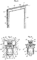
- the 1 1 shows in perspective a window or door 3, a frame 4 with a sliding leaf 2 and a fixed leaf or door panel 60 adjacent thereto.
- an operating element 61 with a switch is provided on a vertical beam 62, which controls a drive device 1.
- the movable wing 2 With actuation of the operating element 61, the movable wing 2; for example from the in 1 having closed position in a, corresponding to the direction of the arrow, not shown position relative to the fixed window frame 4 and the stationarily mounted casement or door panel 60, but on the other hand bring it into a secured shifted ventilation position or a region of a passage opening.
- the wing 2 is hanging over one or more or after 1 bottom-side having carriage 65 supported on a rail 64 on the frame 4 held movable.
- control unit 67 is provided.
- the control unit 67 can also be housed in a wall of a building and is connected to the operating element 61 and the drive device 1 via control lines 66 .
- the operating element 61 can also be a front in the closing direction on the vertical beam 62 - control drive, which also on the vertical beam 62 - not shown - locking means in a locked closed position or in an unlocked open position of the wing 2 transferred.
- Manual actuation by means of an actuation handle with transmission of an actuation linkage to the locking means is also conceivable.
- the movable sash 2 can be driven by the control element 61, not shown, automatically or via the manual operating handle from the 1 having closed position by a coupled connection of the actuating linkage to the carriage 65 in a raised open position in order to then be moved by the drive device 1 can.
- both actuation variants described above can also be arranged in a window or a door 3, which can be selected according to the requirements and resemble the character of a hybrid system.
- additional drives are also connected to the control lines 66 and linked to the control unit 67 .
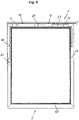
- a special fitting arrangement is installed between the movable wing 2 and the fixed frame 4, namely a so-called system for sliding sashes or movable lifting Sliding sash provided by which in the 1 for the sake of simplicity, only the operating element 61 on the wing 2, a part of a lower rail 64 for the carriage 65 and an upper guide rail 10 after 2 can be hinted at.
- the drive device 1 comprises a drive motor 5 arranged on the wing side with a threaded spindle 6 driven thereon figure 5 and 7 positively guided around a toothed rack element 7 arranged on the window frame 4 .
- the drive device 1 in the installed position of the wing 2 almost completely in a recess or receiving groove 8 of an upper, horizontal beam 9 of the movable wing 2 and arranged on the frame 4 guide rail 10 is arranged lying covered.
- the drive motor 5 and the threaded spindle 6 are mounted as a structural unit in a housing 11 .
- the toothed rack element 7 is almost completely encompassed by a guide cross section of the guide rail 10 that forms a support.
- a gap in the guide rail 10 forms an opening and thus the possibility of coupling between the components arranged on the sash 2 and the components of the drive device 1 mounted on the frame 4.
- the drive motor 5 and the threaded spindle 6 is arranged off-axis perpendicular to the housing 11 and thus to the recess or receiving groove 8 of the wing 2, with the drive motor 5 after 3 facing a bottom plate 13 of the housing 11 and thus a bottom 14 of the recess or receiving groove 8 and the threaded spindle 6 is spaced from the bottom 14 in the direction of the toothed rack element 7 .
- the drive motor 5 achieves the greatest possible installation space in the housing 11, with the threaded spindle 6 being given the necessary free space to develop the thread pitch for interaction with the rack element 7.
- a latching member 15 is provided which can be clipped into a recess 17 of the housing 11 in a non-positive manner.
- elastic locking projections are provided with inlet bevels on the outside of the locking member 15, correspondingly adapted to the recess 16.
- the locking projections snap into the recess 16 of the housing 11 with a slight spring force and form a detachable connection with the housing 11.
- the drive motor 5 and the threaded spindle 6 can be preassembled with the shaft 12 and a carriage 30 as an integral structural unit by means of the latching member 15 in the housing 11 in a fixing position.
- the housing 11 enables the drive motor 5 to be securely accommodated and fastened, and the threaded spindle 6 to be supported in a functional manner and protected from dirt and damage. As a result, the integral structural unit is easily accessible at the same time and can also be replaced if necessary. With the formation of the recess 16 in the housing 11 as a slot, the locking member 15 can be moved in the locked position.
- the moveable mounting of the latching element 15 with transmission to the drive motor 5 via the flexible shaft 12 to the threaded spindle 6 with the carriage 30 enables tolerances to be compensated for and adaptation to a movement of the lift-and-slide sash 2 when it is raised and lowered to the frame 4.
- the movable wing 2 comprises four bars 9, 22, 62, 63, which are designed as hollow profiles, in particular as aluminum or plastic profiles, or as solid profiles consisting of wood.
- the bars contain prefabricated recesses or grooves for concealed assembly of fitting components.
- the drive device 1 is provided in the upper horizontal beam 9, which is arranged to the vertical beam 22 directed.
- the wing-side components of the drive device 1, in particular the housing 11, are designed to be adapted in height H and width B to the recess or receiving groove 8 of the upper horizontal strut 9 of the wing 2. Additional work steps for mounting the drive device 1 on the wing 2 are therefore omitted.
- the housing 11 is designed as a U-shaped cross-sectional contour, the respective side walls 17 starting from the base plate 13 varying in height over the length L of the housing 11 .
- the strip-shaped side walls 17 are of different heights due to functional, bearing or protective properties.
- the maximum height of the housing 11 is reached at the bearing points of the threaded spindle 6.
- the respective longitudinal ends 18, 19 follow 7 and 8 of the housing 11 forms a positive and/or non-positive connection with the limiting and fastening parts 20, 21 fastened to the wing 2.
- Housing 11, together with the wing-side components of the drive device 1, is inserted as a one-piece component from an open end of the upper horizontal spar 9 of the wing 2 into the recess or receiving groove 8, with one end 18 of the housing 11 having a horizontally and vertically position-fixed form-fit connection with a in the recess or receiving groove 8 by a fastening screw positively fastened limiting part 20 is received.
- this points to the other end 19 and to the vertical spar 22 of the movable wing 2 figure 5 arranged fastening part 21 has a circular carrier 23 with a bore 24, which positively engages in a receptacle arranged on the upper horizontal beam 9 below the recess or receiving groove 8 and forms a non-positive connection with the movable wing 2 by means of a fastening screw.
- the wing 2 is equipped with another roller at the other end of the upper horizontal beam 9, which is also attached to the wing 2 in a positive and/or non-positive manner.
- the rollers attached to the side of the wing 2 ensure that the upper horizontal area of the movable wing 2 can be moved securely.
- two spaced uprights 28, 29 extend to the maximum height of the housing 11 and end, starting from the base plate 13 in the direction of the toothed rack element 7, almost at the same height as the carriage 30.
- the housing 11 forms a kind of receptacle for the carriage 30, in which the threaded spindle 6 is rotatably mounted.
- the drive motor 5 is connected via a clutch to the drivingly rotatable shaft 12, which in turn is connected to a threaded rod of the threaded spindle 6, which is rotatably mounted around the stationary carriage 30 8 and 9 , is coupled.
- the carriage 30 which is secured against rotation in the housing 11 , can be moved along the guide rail 10 .
- the threaded spindle 6 is rotationally connected to the rack element 7 by means of a thread 34 and is designed as a cylindrical round rod 31, 32 at the respective ends in an extension of the central axis.
- the carriage 30 is made of two mold halves 35, 36, which form a square or a rectangle in cross section by means of a positive and/or non-positive connection form.
- the carriage 30 has window-like openings 39, 40 on the respective side surfaces 37, 38, into which the thread 34 of the threaded spindle 6 protrudes.
- the openings 39, 40 can contribute as a safeguard against unintentional displacement of the threaded spindle 6.
- the respective ends of the mold halves 35, 36 have 9 and 10 semicircular cutouts 41, 42; 43, 44, which form a circular section for mounting the cylindrical rod 31, 32 for a rotary movement of the threaded spindle 6 by joining.
- a guide carriage 46 is formed on the rack element 7 directed outside 45 of the carriage. Since the guide carriage 46 is located above the lead screw 6, the rack member 7 engages between the guide carriages 46 through a groove for cooperation with the lead screw 6.
- the rack element 7 is after 7 and 12 formed of toothed segments 47, which are modularly connected to each other and form an integral unit.
- the toothed segment 47 after 12 consists preferably of a plastic produced by injection molding or die casting and is after 14 T-shaped in cross section.
- the T-shape is created by the shape of the profile groove 54 and the opening 53 of the guide rail 10.
- the toothed segment 47 is for use in the guide rail 10 after 15 at the sides 48, 49 through an angle W and has a rhombus-shaped base 50 which is stepped at the respective ends 51, 52. After 3 the toothed segment 47 is pushed through the opening 53 of the attachable C-shaped undercut profile groove 54 of the guide rail 10 on the window frame 4 of the window or a door 3, through which the toothed segment 47 with the carriage 30 on the leaf 2 and threaded spindle 6 of the drive device 1 is operatively connected.
- toothed segments 47 As soon as more toothed segments 47 after the longitudinally displaceable engaging position 3 and 6 have reached in the guide rail 10, can be the toothed segments 47 by means of the stepped ends 51, 52 to form a unit 7 - connect to a rack element 7 - without showing the guide rail 10.
- the stepped ends 51, 52 of the toothed segments 47 are stair-shaped and have an undercut at the transition of the step or stairway, so that when the toothed segments 47 are screwed in, a form-fitting, interlocking linkage results.
- a secure, engaging position in the profiled groove 54 of the guide rail 10 is achieved.
- the toothed segment 47 When the longitudinal installation position is reached, ie the final assembly state of the rack element 7 in the profile groove 54 of the guide rail 10, the toothed segment 47 is operatively connected to the carriage 30 located on the wing 2 and the threaded spindle 6 of the drive device 1.
- Also provided on the top surface 55 are projections of thread flanks 57 which, in operative connection with the threaded spindle 6, convert a rotational movement into a translational movement for displacing the wing 2 in the longitudinal direction of the guide rail 10.
- connection of the sash-side components of the drive device 1 via the carriage 30 to the toothed rack element 7 of the drive device 1 arranged on the window frame 4 via the guide rail 56 also automatically secures the final assembly position of the drive device 1 for an unintentional adjustment of the components and for an operating state for automatic displacement of the Window or door 3 in the horizontal direction.
- the drive device 1 can only be dismantled after the carriage 30 has been released from the form-fit connection of the guide rail 56 of the toothed rack element 7 .
Description
- Die Erfindung betrifft eine Tür oder Fenster mit einem verschiebbaren Flügel als Schiebeflügel oder verschiebbaren Hebe-Schiebeflügel, einem Blendrahmen, in dem der Flügel verschiebbar gehalten ist, und einer Antriebsvorrichtung.
- Die verschiebbaren Flügel von Systemen als Schiebeflügel oder Hebe-Schiebeflügel für ein Fenster oder eine Tür weisen häufig eine relativ hohe Masse auf. Beim Verschieben des Flügels, insbesondere beim Anschieben aus einer Standposition des Flügels muss zum Öffnen eine hohe Kraft aufgenommen werden. Auch das Schließen erfordert ein Aufbringen eines Widerstandes gegen die Gewichtskraft des Flügels. Bekannte Antriebe sind sichtbar auf dem Fenster oder der Tür montiert und werden mit einer zusätzlichen Abdeckung abgeschirmt, was die Optik stark beeinträchtigt. Ebenso wird das Verletzungsrisiko bei der Montage durch störend aufliegend sichtbare Bauteile erhöht. Ferner bieten sichtbare Bauteile mehr Möglichkeiten einer Manipulation von außen. Eine Montage einer solchen Antriebsvorrichtung erweist sich aus dem bekannten Stand der Technik ebenso als aufwendig.
- Des Weiteren sind verdeckt liegend angeordnete Antriebe bekannt, die sich jedoch nur mit hohen Aufwand und in nur wenig geeignete Profilsysteme integrieren lassen. Insbesondere erweist sich der Fräsaufwand im Profil als sehr hoch und kann zu hohen Kosten und zur Schwächung der Struktur der Fenster- oder Türelemente führen.
- Aus der
EP 2 063 058 B1 ist ein Schiebefenster oder eine Schiebetür mit einem Blendrahmen bekannt geworden, in dem mindestens ein Schiebeflügel verfahrbar gehalten ist, der über einen Antrieb bewegbar und über Verriegelungsmittel mit dem Blendrahmen koppelbar ist, wobei der Schiebeflügel vier aneinander festgelegte Rahmenprofile aufweist. Dabei umfasst der Antrieb eine angetriebene Antriebsrolle, um die ein am Blendrahmen festgelegtes Spannelement gewickelt ist, wobei das Spannelement über zwei Umlenkrollen geführt ist und in eine Hohlkammer des Rahmenprofils einläuft. - Die vorliegende Steuervorrichtung ist zur Führungsschiene aufgrund des vertikalen Einbaus in einem vertikalen Holm des Flügels nur über eine Umlenkung zur Führungsschiene erreichbar, was den Aufbau kostenaufwendig verkompliziert und entsprechend viel Bauraum im Flügel benötigt. Außerdem sind die Bauteile der Steuervorrichtung von der Führungsschiene weit voneinander beabstandet verteilt, was eine Montage aufgrund einzelner Bauteilekomponenten erschwert.
- Weiter wird verwiesen auf die
EP 1 914 372 A2 . Dabei ist eine als Schiebetür oder Schwenkschiebetür ausgebildete Fahrgasttür für Fahrzeuge des öffentlichen Personenverkehrs mit mindestens einem in seiner Längsrichtung verschiebbaren Türblatt vorgesehen, das in einer Tragführung aufgehängt und verschiebbar geführt ist. Die Tragführung weist dazu eine Linearführung mit mindestens einer Führungsschiene auf, an welcher ein Führungsschlitten geführt ist, und an dem über einen Tragarm das Türblatt aufgehängt ist. Die Tragführung ist aufgrund des konstruktiven Aufbaus nicht in der Lage, in ein Fenster oder Türsystem verdeckt eingebaut werden zu können. Ferner ist die Ausgestaltung aufwendig in der Montage und mit der Vielzahl von Bauteilen kostenaufwendig in der Herstellung. - Ebenfalls ist die
WO 2014/097211 A1 bekannt geworden, welche eine Tür oder Fenster mit einem verschiebbaren Flügel als Schiebeflügel oder verschiebbaren Hebe-Schiebeflügel, einem Blendrahmen, in dem der Flügel verschiebbar gehalten ist, und einer Antriebsvorrichtung, wobei die Antriebsvorrichtung zum Verschieben des Flügels einen rahmenseitig angeordneten Antriebsmotor mit einer daran angetriebenen Gewindespindel umfasst, die um ein am Flügel angeordnetes Zahnstangenelement zwangsgeführt ist, wobei der Antriebsmotor und die Gewindespindel als eine Baueinheit bildend in einem Gehäuse gelagert sind. - Außerdem offenbart die
DE 20 2005 000165 U1 eine Antriebsvorrichtung, bei der die Motor-Getriebe-Einheit in einer Aufnahmenut eines oberen, horizontalen Holms des Flügels und das Zahnstangenelement in der Führungsschiene angeordnet ist. Diese Einheit weist ein Kegelgetriebe auf, das die Drehung der Motorwelle um eine horizontale Achse in eine Drehung einer Welle um eine vertikale Achse übersetzt, wobei diese Welle ein Ritzel antreibt, welches mit dem Zahnstangenelement im Eingriff steht. Der Laufwagen der Schiebetür ist derart ausgebildet, dass der obere, horizontale Holm des Flügels und die Führungsschiene in vertikaler Richtung voneinander beabstandet sind. - Die Aufgabe der vorliegenden Erfindung liegt daher in der Beseitigung der bekannten Mängel und stellt demgegenüber mit geringen Kosten und geringem Bauraum einen Antrieb für einen verschiebbaren Flügel als Schiebeflügel oder Hebe-Schiebeflügel für große Tragmöglichkeiten und optimaler Führung für ein Fenster oder eine Tür bereit, der außerdem auf einfache, schnelle, sichere und präzise Weise auch nachträglich montiert und justiert, sowie demoniert werden kann.
- Gelöst wird diese Aufgabe durch eine Tür oder Fenster mit den Merkmalen des Patentanspruchs 1.
- Dabei weist der bewegliche Flügel vorzugsweise zumindest zwei Laufwagen mit jeweils Rollen auf, um auf einer Laufschiene in einer Richtung parallel zur Erstreckung des Flügels oder entlang einer Laufschiene verschoben zu werden. Zur automatisch verschiebbaren Betätigung des Flügels, ist vorzugsweise an einem vertikalen Holm ein Bedienungselement mit einem Schalter vorgesehen, welches eine Antriebsvorrichtung steuert. Mit Betätigung des Bedienungselementes lässt sich der bewegliche Flügel beispielsweise aus einer Schließlage in eine gegenüber einem feststehenden Blendrahmen und einem ortsfestmontierten Flügel bzw. Türfeld verschieben. Andererseits lässt sich der Flügel auch damit in eine gesicherte verschobene Lüftungslage oder einen Bereich einer Durchgangsöffnung bringen. Der Flügel ist dabei in vorteilhafter Weise über bodenseitig aufweisende Laufwagen auf einer Laufschiene abgestützt an dem Blendrahmen verfahrbar gehalten.
- Eine Bedienung der Antriebsvorrichtung über eine Fernbedienungseinheit oder ein Smart Home System ist ebenfalls denkbar. Dazu ist an dem Fenster oder der Tür eine Steuereinheit vorgesehen. Die Steuereinheit kann ebenfalls in einer Wand eines Gebäudes untergebracht werden und ist mit dem Bedienungselement und der Antriebsvorrichtung über Steuerleitungen verbunden.
- Das Bedienungselement kann außerdem einen in Schließrichtung vorne am vertikalen Holm angeordneten Antrieb steuern, welcher ebenfalls am vertikalen Holm aufweisende Verriegelungsmittel in eine verriegelte Schließlage oder in eine entriegelte geöffnete Position des Flügels überführt. Eine manuelle Betätigung mittels einer Betätigungshandhabe mit Übertragung eines Betätigungsgestänges auf die Verriegelungsmittel ist ebenfalls denkbar.
- Bei einem System eines verschiebbaren Hebe-Schiebeflügels eines Fensters oder einer Tür, lässt sich der bewegliche Flügel durch den Antrieb über das Bedienungselement automatisch oder über die manuelle Betätigungshandhabe aus der Schließlage durch eine gekoppelte Verbindung des Betätigungsgestänges auf die Laufwagen in eine angehobene Öffnungsstellung befördern, um anschließend durch die Antriebsvorrichtung verschoben werden zu können.
- Ebenso können auch beide voran beschriebenen Betätigungsvarianten in einem Fenster oder einer Tür angeordnet sein, welche den Anforderungen entsprechend ausgewählt werden können und dem Charakter eines Hybridsystems gleichen. Dem System ausgewählte zusätzliche Antriebe sind zusätzlich mit den Steuerleitungen verbunden und mit der Steuereinheit verknüpft.
- Damit diese Stellungen des Flügels relativ zum feststehenden Blendrahmen sowie zum fest montierten Flügel bzw. zum festen Türfeld möglich sind, wird zwischen dem beweglichen Flügel und dem feststehenden Blendrahmen eine besondere Beschlaganordnung, nämlich ein sogenanntes System für Schiebeflügel oder verschiebbaren Hebe-Schiebeflügel vorgesehen.
- In vorteilhafter Weise umfasst die Antriebsvorrichtung zum Verschieben des Flügels einen flügelseitig angeordneten Antriebsmotor mit einer daran angetriebenen Gewindespindel. Die Gewindespindel ist um ein am Blendrahmen angeordnetes Zahnstangenelement zwangsgeführt. Eine verdeckt liegende Anordnung der Antriebsvorrichtung wird dadurch ermöglicht, dass die Antriebsvorrichtung in Einbaulage des beweglichen Flügels nahezu vollständig in einer Ausnehmung oder Aufnahmenut eines oberen, horizontalen Holms des beweglichen Flügels und einer am Blendrahmen angeordneten Führungsschiene montiert ist. Für eine optimale Lagerung der Antriebsbauteile der Antriebsvorrichtung, sind der Antriebsmotor und die Gewindespindel als eine Baueinheit bildend in einem Gehäuse gelagert. Das Zahnstangenelement wird nahezu vollständig von der Führungsschiene umgriffen. Ein Spalt in der Führungsschiene bildet eine Öffnung und damit die Möglichkeit zur Kopplung zwischen den flügelseitigen Bauteilen und den Blendrahmen seitigen Bauteilen der Antriebsvorrichtung.
- Als kostengünstig und mit konstruktivem Vorteil erweist sich das Merkmal, dass der Antriebsmotor und die Gewindespindel für eine rotatorische Übertragung der Bewegung durch eine formschlüssige Verbindung einer flexiblen Welle oder einem Kardan in Längsrichtung zur Verschieberichtung des Flügels antriebsverbunden sind.
- Der Antriebsmotor und die Gewindespindel sind senkrecht in der Höhe und horizontal in Längsrichtung zum Gehäuse und damit zur Ausnehmung oder Aufnahmenut des beweglichen Flügels versetzt angeordnet, wobei der Antriebsmotor einer Bodenplatte des Gehäuses und damit einem Boden der Ausnehmung oder Aufnahmenut zugewandt ist und die Gewindespindel von dem Boden in Richtung Zahnstangenelement beabstandet ist. Mit der Verlagerung der Bauteile des Antriebsmotors und der Gewindespindel in Höhe innerhalb des Gehäuses, erreicht der Antriebsmotor einen größtmöglichen Bauraum im Gehäuse, wobei die Gewindespindel den nötigen Freiraum zur Entfaltung der Gewindesteigung für ein Zusammenspiel mit dem Zahnstangenelement erhält.
- Ein einfaches Zusammenfügen und eine einfache Montage der im Gehäuse aufweisenden Antriebsbauteile wird dadurch erreicht, dass, unterhalb des Antriebsmotors auf der Seite zur Bodenplatte des Gehäuses ein Rastglied vorgesehen ist, welches in eine Ausnehmung des Gehäuses kraftschlüssig einklipsbar ist. Dazu sind an der Außenseite des Rastglieds, der Ausnehmung am Gehäuse angepasst, elastische Rastvorsprünge mit Einlaufschrägen versehen. Bei der Montage rasten die Rastvorsprünge in die Ausnehmung des Gehäuses mit leichter Federkraft ein und bilden eine lösbare Verbindung mit dem Gehäuse. Der Antriebsmotor und die Gewindespindel mit der Welle und einem Schlitten lassen sich als integrale Baueinheit vormontiert mittels des Rastglieds in das Gehäuse fixierend positionieren. Das Gehäuse ermöglicht dem Antriebsmotor eine sichernde Aufnahme und Befestigung und der Gewindespindel eine funktionsgerechte Lagerung und ein Schutz vor Schmutz und Beschädigungen. Dadurch ist gleichzeitig die integrale Baueinheit leicht zugänglich und kann bei Bedarf auch ausgewechselt werden. Außerdem ist das Rastglied in der Ausnehmung des Gehäuses verschiebbar gelagert. Dazu ist die Ausnehmung als Langloch ausgebildet. Mit beweglicher Lagerung der Antriebsbauteile, bestehend aus dem Antriebsmotor, der Gewindespindel mit der Welle und dem Schlitten, über das Rastglied in der Ausnehmung, lassen sich sowohl möglich entstehende Toleranzen als auch eine Verstellung des Flügels zum Blendrahmen in der Höhe, insbesondere bei einem Hebe-Schiebeflügel, über die flexible Welle ausgleichen.
- Der bewegliche Flügel umfasst vier Holme, die als Hohlprofile, insbesondere als Aluminium- oder Kunststoffprofile oder als Vollprofile bestehend aus Holz ausgebildet sind. Die Holme enthalten vorgefertigte Ausnehmungen oder Aufnahmenuten zur verdeckten Montage von Beschlagbauteilen, insbesondere für die Antriebsvorrichtung. So ist in dem oberen horizontalen Holm und zum vertikalen Holm weisend die Antriebsvorrichtung in einer Ausnehmung oder Aufnahmenut montiert. Vorzugsweise sind die flügelseitigen Bauteile der Antriebsvorrichtung in der Höhe H und der Breite B der Ausnehmung oder Aufnahmenut des oberen horizontalen Holms des Flügels angepasst ausgebildet. Zusätzliche Arbeitsschritte für eine Montage der Antriebsvorrichtung am Flügel bleiben somit aus.
- In bevorzugter Ausgestaltung ist das Gehäuse als U- förmige Querschnittskontur ausbildet, wobei über die Länge des Gehäuses die jeweiligen Seitenwandungen ausgehend von der Bodenplatte in der Höhe variieren. Die leistenförmig ausgebildeten Seitenwandungen sind aufgrund funktioneller, lager- oder schutzbildenden Eigenschaften unterschiedlich hoch. Die maximale Höhe des Gehäuses wird an den Lagerstellen der Gewindespindel erreicht.
- Zur einfachen Befestigung ist die Antriebsvorrichtung in dem beweglichen Flügel lösbar in der Aufnahmenut fixiert. Dazu gehen die jeweiligen längsseitigen Enden des Gehäuses eine form- und/ oder kraftschlüssige Verbindung mit am Flügel befestigten Begrenzungs- und Befestigungsteilen ein. Das Gehäuse wird zusammen mit den flügelseitigen Bauteilen der Antriebsvorrichtung als einteiliges Bauteil bildend von einem offenen Ende des oberen horizontalen Holms des beweglichen Flügels in die Ausnehmung oder Aufnahmenut eingeführt. Ein Ende des Gehäuses bewirkt eine horizontal und vertikal lagefixierte Formschlussverbindung mit einem in der Ausnehmung oder Aufnahmenut mittels eines durch eine Befestigungsschraube kraftschlüssig befestigten Begrenzungsteils. Das andere Ende des Gehäuses wird von einem weiteren Befestigungsteil übergreifend in den horizontalen und vertikalen Bewegungslagen gehalten, wobei das zum vertikalen Holm des Flügels weisende Befestigungsteil einen kreisrunden Träger mit einer Bohrung aufweist, der in eine am oberen horizontalen Holm unterhalb der Ausnehmung oder Aufnahmenut angeordnete Aufnahme formschlüssig eingreift und durch eine Befestigungsschraube mit dem beweglichen Flügel eine kraftschlüssige Verbindung eingeht.
- Zur vereinfachten Montage und kostengünstigen Herstellung ist an dem zum freien Ende des oberen horizontalen Holms angeordneten Befestigungsteil eine in Richtung der Führungsschiene quer und von der Ausnehmung oder Aufnahmenut des beweglichen Flügels beabstandet kugelgelagerte Laufrolle angeordnet, die in seitlich angeordneten Querführungen der Führungsschiene verschiebbar gelagert ist. Ebenso ist am anderen Ende des oberen horizontalen Holms vorzugsweise eine weitere Laufrolle vorgesehen, die am Flügel form- und /oder kraftschlüssig befestigt ist. Die an dem Flügel befestigten Laufrollen tragen zu einem sicheren verschiebbaren Halt des oberen horizontalen Bereichs des beweglichen Flügels zum Blendrahmen bei. Zum Führen des Flügels sind anstatt kugelgelagerte Laufrollen auch höhenausgleichbare Gleitstücke oder andere Bauteile einsetzbar.
- Für eine gesicherte Aufnahme des Schlittens und der Gewindespindel, erstrecken sich zwei voneinander entfernte Ständer des Gehäuses von der Bodenplatte in Richtung Zahnstangenelement, auf eine maximale Höhe des Gehäuses bis nahezu auf die gleiche Höhe des Schlittens.
- Einfach und kostengünstig im konstruktiven Aufbau erweist sich, dass der Antriebsmotor über eine Kupplung mit der antreibend drehbaren Welle verbunden ist, und die Welle wiederum mit einer um den ortsfest gelagerten Schlitten herum drehbar gelagerten Gewindestange der Gewindespindel gekuppelt ist. Der im Gehäuse drehgesichert aufweisende Schlitten, lässt sich hingegen entlang der Führungsschiene verfahren. Dazu ist die Gewindespindel mittels eines Gewindes drehwirksam mit dem Zahnstangenelement verbunden. An den jeweiligen Enden in Verlängerung der Mittelachse, ist die Gewindespindel als zylindrischer Rundstab ausgebildet.
- Vorzugsweise wird der Schlitten aus zwei Formhälften gefertigt, welche durch form- und/ oder kraftschlüssige Verbindung im Querschnitt ein Quadrat oder ein Rechteck ausbilden. Um einen größtmöglichen Bauraum für das Gewinde der Gewindespindel zu erreichen, weist der Schlitten an den jeweiligen Seitenflächen fensterartige Öffnungen auf, in welche das Gewinde der Gewindespindel hineinragt. Der Durchmesser des Gewindes reicht durch die Öffnungen ragend bis an die außenseitigen Wandungen des Gehäuses. Zusätzlich können die Öffnungen als Sicherung gegen ein unbeabsichtigtes Verschieben der Gewindespindel beitragen.
- Zur einfachen Kupplung der Gewindespindel, weisen die jeweiligen Enden der Formhälften des Schlittens halbkreisförmige Ausschnitte auf, welche durch Fügen einen kreisförmigen Ausschnitt zur Lagerung des zylindrischen Rundstabs der Gewindespindel für eine rotatorische Bewegung des Gewindes ausbilden.
- Zum gleitführenden Verbinden in Längsrichtung der Führungsschiene des beweglichen Flügels zum Blendrahmen und damit der flügelseitigen Bauteile der Antriebsvorrichtung zu den Bauteilen des Zahnstangenelementes an dem Blendrahmen, ist auf der zum Zahnstangenelement gerichteten Außenseite des Schlittens ein Führungsschlitten angeformt. Mit Anordnung des Führungsschlittens oberhalb des Gewindes der Gewindespindel, greift das Zahnstangenelement zwischen den Führungsschlitten durch eine Nut für ein Zusammenwirken mit der Gewindespindel ein.
- Alle Bauteilekomponenten der Antriebsvorrichtung werden zur Vereinfachung der Montage vor dem Einbau in das Gehäuse und in die Führungsschiene montiert. Als eine einfache Handhabung der Montage des Zahnstangenelementes in die Führungsschiene überzeugt die modulare Aneinanderreihung von Bauteilen baulich gleicher Zahnsegmente, die sowohl von der offenen Seite oder auch in die Öffnung der im Querschnitt U-förmig ausgebildeten Führungsschiene in die Profilnut oder den Kanal der Führungsschiene eingefügt werden können. Zum Einfügen der Zahnsegmente durch die sich auf der Gesamtlänge der Führungsschiene erstreckende schlitzartige Öffnung, ist das Zahnsegment in Kontur und Länge gesondert ausgebildet.
- Das Zahnsegment besteht vorzugsweise aus einem im Spritzgießverfahren hergestellten Kunststoff oder einem Druckguss und ist im Querschnitt T-förmig. Die T-förmige Formgebung entsteht durch die Formgebung der Profilnut der Führungsschiene. Im eingeführten Zustand liegt das Zahnsegment im Innenraum der Profilnut stützend auf bildenden Führungsflächen auf.
- Mit Einhaltung eines einteilig und kostengünstig hergestellten Gegenstandes des Zahnsegmentes, ist das Zahnsegment zum Montieren durch die schlitzartige Öffnung der Führungsschiene und modularen Verkettung einzelner Zahnsegmente an den Seiten über einen Winkel angeschrägt und weist einen als Rhombus geformten Fuß auf, der an den jeweiligen Enden gestuft ist. Aufgrund der in einem Winkel angeschrägten Seiten mit Abstimmung der Länge des Zahnsegmentes, gelingt es, mit leicht versetzt gedrehter Lage des Zahnsegmentes zur Längsrichtung der Führungsschiene und damit der schlitzartigen Öffnung, das Zahnsegment durch die Öffnung in eine längsverschiebbare hintergreifende Lage der Führungsschiene zu montieren.
- Sobald weitere Zahnsegmente die längsverschiebbare hintergreifende Lage in der Profilnut der Führungsschiene erreicht haben, lassen sich die Zahnsegmente mittels der gestuften Enden zu einer Baueinheit eines Zahnstangenelementes verbinden.
- Dazu sind die gestuften Enden der Zahnsegmente Treppen förmig ausgebildet und weisen beim Übergang der Stufe oder Treppe einen Hinterschnitt auf, so dass sich mit Eindrehen der Zahnsegmente eine formschlüssige ineinandergreifend verbindende Verkettung ergibt. In Wirkverbindung der gefügten Zahnsegmente, wird eine gesicherte hintergreifende Position in der Profilnut der Führungsschiene erreicht.
- Mit Erreichen der längserstreckenden Einbaulage, d.h., des Endmontagezustands des Zahnstangenelementes in der Profilnut der Führungsschiene, sind die Zahnsegmente mit dem am beweglichen Flügel befindlichen Schlitten und der Gewindespindel der Antriebsvorrichtung wirkverbunden. Dazu weist das Zahnsegment auf einer Deckfläche in Richtung der flügelseitigen Bauteile der Antriebsvorrichtung eine Führungsschiene auf, die mit dem Führungsschlitten des Schlittens in formschlüssig gleitend beweglicher Wirkverbindung steht. Weiter sind auf der Deckfläche Ansätze von Gewindeflanken vorgesehen, die in der Breite des Führungsschlittens des Schlittens angepasst, in wirksamer Verbindung mit der Gewindespindel eine rotatorische Bewegung in eine translatorische Bewegung zum Verschieben des Flügels in Längsrichtung der Führungsschiene umwandeln.
- Das Verbinden der flügelseitigen Bauteile der Antriebsvorrichtung über den Schlitten mit dem am Blendrahmen angeordneten Zahnstangenelement der Antriebsvorrichtung über die Führungsschiene, sichert außerdem automatisch die Endmontagestellung der Antriebsvorrichtung für ein unbeabsichtigtes Verstellen der Bauteile und für ein Betriebszustand zum automatischen Verschieben des Fensters oder der Tür in horizontaler Richtung. Eine Demontage der Antriebsvorrichtung, ist erst nach dem Lösen des Schlittens aus der formschlüssigen Verbindung aus der Führungsschiene des Zahnstangenelementes möglich.
- Bevorzugte Ausführungsbeispiele der Erfindung sind in der Zeichnung schematisch dargestellt und werden nachfolgend mit Bezug zu den Figuren der Zeichnung näher erläutert.
- Es zeigen:
- Fig. 1
- eine perspektivische Ansicht eines verschiebbaren Flügels als Schiebeflügel oder verschiebbaren Hebe-Schiebeflügel eines Fensters oder einer Tür,
- Fig. 2
- eine perspektivische Ansicht eines verschiebbaren Flügel als Schiebeflügel oder verschiebbaren Hebe-Schiebeflügel nach
Fig. 1 mit einer Führungsschiene ohne Blendrahmen und Festfeld eines Fensters oder einer Tür, - Fig. 3
- eine Schnittdarstellung des Fensters oder der Tür nach
Fig. 1 durch die Führungsschiene und die Antriebsvorrichtung, - Fig. 4
- eine Schnittdarstellung nach
Fig. 7 durch die Antriebsvorrichtung, - Fig. 5
- eine Vorderansicht des verschiebbaren Flügels als Schiebeflügel oder verschiebbaren Hebe-Schiebeflügel nach
Fig. 2 mit der Führungsschiene ohne Blendrahmen und Festfeld des Fensters oder einer Tür, - Fig. 6
- ein perspektivischer Ausschnitt nach
Fig. 2 mit der Antriebsvorrichtung und der Führungsschiene, - Fig. 7
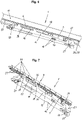
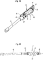
- eine perspektivische Ansicht der Antriebsvorrichtung,
- Fig. 8
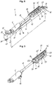
- eine perspektivische Ansicht der Antriebsvorrichtung ohne ein Zahnstangenelement,
- Fig. 9
- eine perspektivische Ansicht der Antriebsvorrichtung ohne ein Gehäuse nach
Fig. 8 , - Fig. 10
- eine perspektivische Ansicht einer Gewindespindel mit einer Formhälfte eines Schlittens der Antriebsvorrichtung nach
Fig. 8 , - Fig. 11
- eine Vorderansicht der Gewindespindel nach
Fig. 10 , - Fig. 12
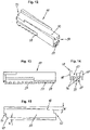
- eine perspektivische Ansicht eines Zahnsegmentes des Zahnstangenelementes nach
Fig. 7 , - Fig. 13
- eine Vorderansicht eines Zahnsegmentes des Zahnstangenelementes nach
Fig. 12 , - Fig. 14
- eine Seitenansicht des Zahnsegmentes nach
Fig. 12 und - Fig. 15
- eine Draufsicht des Zahnsegmentes nach
Fig. 12 . - Die
Fig. 1 zeigt in perspektivischer Ansicht eines Fensters oder einer Tür 3, einen Blendrahmen 4 mit einem verschiebbaren Flügel 2 und einem fest montierten Flügel bzw. Türfeld 60, der diesem benachbart ist. Zur Betätigung des beweglichen Flügels 2, ist an einem vertikalen Holm 62 ein Bedienungselement 61 mit einem Schalter vorgesehen, welches eine Antriebsvorrichtung 1 steuert. Mit Betätigung des Bedienungselementes 61 lässt sich der bewegliche Flügel 2; beispielsweise aus der inFig. 1 aufweisenden Schließlage in eine, entsprechend der Pfeilrichtung, nicht dargestellte Position gegenüber dem feststehenden Blendrahmen 4 und dem ortsfestmontierten Flügel bzw. Türfeld 60 verschieben, aber andererseits auch in eine gesicherte verschobene Lüftungslage oder einen Bereich einer Durchgangsöffnung bringen. Der Flügel 2 ist dabei über ein oder mehrere hängende oder nachFig. 1 bodenseitig aufweisende Laufwagen 65 auf einer Laufschiene 64 abgestützt an dem Blendrahmen 4 verfahrbar gehalten. - Eine Bedienung der Antriebsvorrichtung 1 über eine Fernbedienungseinheit oder ein Smart Home System ist ebenfalls denkbar. Dazu ist an dem Fenster oder der Tür 3 nach
Fig. 5 eine Steuereinheit 67 vorgesehen. Die Steuereinheit 67 kann ebenfalls in einer Wand eines Gebäudes untergebracht werden und ist mit dem Bedienungselement 61 und der Antriebsvorrichtung 1 über Steuerleitungen 66 verbunden. - Das Bedienungselement 61 kann außerdem einen in Schließrichtung vorne am vertikalen Holm 62 - nicht dargestellte - Antrieb steuern, welcher ebenfalls am vertikalen Holm 62 - nicht darstellte - Verriegelungsmittel in eine verriegelte Schließlage oder in eine entriegelte geöffnete Position des Flügels 2 überführt. Eine manuelle Betätigung mittels einer Betätigungshandhabe mit Übertragung eines Betätigungsgestänges auf die Verriegelungsmittel ist ebenfalls denkbar.
- Bei einem System eines verschiebbaren Hebe-Schiebeflügels 2 eines Fensters oder einer Tür 3, lässt sich der bewegliche Flügel 2 durch den - nicht dargestellten - Antrieb über das Bedienungselement 61 automatisch oder über die manuelle Betätigungshandhabe aus der in den
Fig. 1 aufweisenden Schließlage durch eine gekoppelte Verbindung des Betätigungsgestänges auf die Laufwagen 65 in eine angehobene Öffnungsstellung befördern, um anschließend durch die Antriebsvorrichtung 1 verschoben werden zu können. - Ebenso können auch beide voran beschriebenen Betätigungsvarianten in einem Fenster oder einer Tür 3 angeordnet sein, welche den Anforderungen entsprechend ausgewählt werden können und dem Charakter eines Hybridsystems gleichen. Dem System ausgewählte, zusätzliche Antriebe sind ebenso mit den Steuerleitungen 66 verbunden und mit der Steuereinheit 67 verknüpft.
- Damit diese Stellungen des Flügels 2 relativ zum feststehenden Blendrahmen 4 sowie zum fest montierten Flügel bzw. zum festen Türfeld 60 möglich sind, wird zwischen dem beweglichen Flügel 2 und dem feststehenden Blendrahmen 4 eine besondere Beschlaganordnung, nämlich ein sogenanntes System für Schiebeflügel oder verschiebbaren Hebe-Schiebeflügel vorgesehen, von dem in der
Fig. 1 der Einfachheit halber nur das Bedienungselement 61 am Flügel 2, ein Teil einer unteren Laufschiene 64 für die Laufwagen 65 und eine obere Führungsschiene 10 nachFig. 2 andeutungsweise zu sehen ist. - Nach der
Fig. 8 umfasst die Antriebsvorrichtung 1 einen flügelseitig angeordneten Antriebsmotor 5 mit einer daran angetriebenen Gewindespindel 6. Die Gewindespindel 6 ist nachFig. 5 undFig. 7 um ein am Blendrahmen 4 angeordnetes Zahnstangenelement 7 zwangsgeführt. NachFig. 3 ist die Antriebsvorrichtung 1 in Einbaulage des Flügels 2 nahezu vollständig in einer Ausnehmung oder Aufnahmenut 8 eines oberen, horizontalen Holms 9 des beweglichen Flügels 2 und einer am Blendrahmen 4 angeordneten Führungsschiene 10 verdeckt liegend angeordnet. Der Antriebsmotor 5 und die Gewindespindel 6 sind als eine Baueinheit bildend in einem Gehäuse 11 gelagert. Das Zahnstangenelement 7 wird nahezu vollständig von einem Auflage bildenden Führungsquerschnitt der Führungsschiene 10 umgriffen. Ein Spalt in der Führungsschiene 10 bildet eine Öffnung und damit die Möglichkeit zur Kopplung zwischen den am Flügel 2 angeordneten Bauteilen und den am Blendrahmen 4 montierten Bauteilen der Antriebsvorrichtung 1. - Aus den
Figuren 8 und 9 wird deutlich, dass der Antriebsmotor 5 und die Gewindespindel 6 für eine rotatorische Übertragung der Bewegung durch eine formschlüssige Verbindung mit einer flexiblen Welle 12 oder einem Kardan in Längsrichtung zur Verschieberichtung des Flügels 2 antriebsverbunden sind. - In
Fig. 8 ist der Antriebsmotor 5 und die Gewindespindel 6 senkrecht zum Gehäuse 11 und damit zur Ausnehmung oder Aufnahmenut 8 des Flügels 2 achsversetzt angeordnet, wobei der Antriebsmotor 5 nachFig. 3 einer Bodenplatte 13 des Gehäuses 11 und damit einem Boden 14 der Ausnehmung oder Aufnahmenut 8 zugewandt ist und die Gewindespindel 6 von dem Boden 14 in Richtung Zahnstangenelement 7 beabstandet ist. Mit der Verlagerung der Bauteile des Antriebsmotors 5 und der Gewindespindel 6 in der Höhe, erreicht der Antriebsmotor 5 einen größtmöglichen Bauraum im Gehäuse 11, wobei die Gewindespindel 6 den nötigen Freiraum zur Entfaltung der Gewindesteigung für ein Zusammenspiel mit dem Zahnstangenelement 7 erhält. - Unterhalb des Antriebsmotors 5 auf der Seite zur Bodenplatte 13 des Gehäuses 11 ist nach
Fig. 9 ein Rastglied 15 vorgesehen, welches in eine Ausnehmung 17 des Gehäuses 11 kraftschlüssig einklipsbar ist. Dazu sind an der Außenseite des Rastglieds 15, der Ausnehmung 16 entsprechend angepasst, elastische Rastvorsprünge mit Einlaufschrägen versehen. Bei der Montage rasten die Rastvorsprünge in die Ausnehmung 16 des Gehäuses 11 mit leichter Federkraft ein und bilden eine lösbare Verbindung mit dem Gehäuse 11. Wie inFig. 9 dargestellt, können der Antriebsmotor 5 und die Gewindespindel 6 mit der Welle 12 und einem Schlitten 30 als integrale Baueinheit vormontiert mittels des Rastglieds 15 in das Gehäuse 11 fixierend positioniert werden. Das Gehäuse 11 ermöglicht dem Antriebsmotor 5 eine sichernde Aufnahme und Befestigung, sowie der Gewindespindel 6 eine funktionsgerechte Lagerung und ein Schutz vor Schmutz und Beschädigungen. Dadurch ist gleichzeitig die integrale Baueinheit leicht zugänglich und kann bei Bedarf auch ausgewechselt werden. Mit Ausbildung der Ausnehmung 16 im Gehäuse 11 als Langloch, lässt sich das Rastglied 15 in gerasteter Lage verschieben. Die bewegliche Lagerung des Rastglieds 15 mit Übertragung auf den Antriebsmotor 5 über die flexible Welle 12 auf die Gewindespindel 6 mit dem Schlitten 30, ermöglicht ein Ausgleich von Toleranzen und die Anpassung bei einer Bewegung des Hebe-Schiebeflügels 2 beim Anheben und Absenken zum Blendrahmen 4. - Der bewegliche Flügel 2 umfasst vier Holme 9, 22, 62, 63, die als Hohlprofile, insbesondere als Aluminium- oder Kunststoffprofile, oder als Vollprofile bestehend aus Holz ausgebildet sind. Die Holme enthalten vorgefertigte Ausnehmungen oder Aufnahmenuten zur verdeckten Montage von Beschlagbauteilen. So ist in dem oberen horizontalen Holm 9 die Antriebsvorrichtung 1 vorgesehen, die zum vertikalen Holm 22 gerichtet angeordnet ist. Vorzugsweise sind die flügelseitigen Bauteile der Antriebsvorrichtung 1, insbesondere das Gehäuse 11, in der Höhe H und der Breite B der Ausnehmung oder Aufnahmenut 8 des oberen horizontalen Holms 9 des Flügels 2 angepasst ausgebildet. Zusätzliche Arbeitsschritte für eine Montage der Antriebsvorrichtung 1 am Flügel 2 bleiben somit aus.
- In
Fig. 8 ist das Gehäuse 11 als U- förmige Querschnittskontur ausgebildet, wobei über die Länge L des Gehäuses 11 die jeweiligen Seitenwandungen 17 ausgehend von der Bodenplatte 13 in der Höhe variieren. Die leistenförmig ausgebildeten Seitenwandungen 17 sind aufgrund funktioneller, lager- oder schutzbildenden Eigenschaften unterschiedlich hoch. Die maximale Höhe des Gehäuses 11 wird an den Lagerstellen der Gewindespindel 6 erreicht. - Um die Antriebsvorrichtung 1 in dem beweglichen Flügel 2 lösbar fixiert in der Aufnahmenut 8 nach
Fig. 1 undFig. 3 einfach zu verbinden, gehen die jeweiligen längsseitigen Enden 18, 19 nachFig. 7 undFig. 8 des Gehäuses 11 eine form- und/ oder kraftschlüssige Verbindung mit am Flügel 2 befestigten Begrenzungs- und Befestigungsteilen 20, 21 ein. Dabei wird das Gehäuse 11 zusammen mit den flügelseitigen Bauteilen der Antriebsvorrichtung 1 als einteiliges Bauteil bildend von einem offenen Ende des oberen horizontalen Holms 9 des Flügels 2 in die Ausnehmung oder Aufnahmenut 8 eingeführt, wobei das eine Ende 18 des Gehäuses 11 eine horizontal und vertikal lagefixierte Formschlussverbindung mit einem in der Ausnehmung oder Aufnahmenut 8 durch eine Befestigungsschraube kraftschlüssig befestigten Begrenzungsteil 20 eingeht. Weiter inFig. 8 ersichtlich, weist das am anderen Ende 19 und zum vertikalen Holm 22 des beweglichen Flügels 2 nachFig. 5 angeordnete Befestigungsteil 21 einen kreisrunden Träger 23 mit einer Bohrung 24 auf, der in eine am oberen horizontalen Holm 9 unterhalb der Ausnehmung oder Aufnahmenut 8 angeordnete Aufnahme formschlüssig eingreift und durch eine Befestigungsschraube mit dem beweglichen Flügel 2 eine kraftschlüssige Verbindung eingeht. - An dem zum vertikalen Holm 22 des oberen horizontalen Holms 9 weisenden Ende des beweglichen Flügels 2 nach
Fig. 1 undFig. 7 , ist in der Aufnahmenut 8 an dem Befestigungsteil 21 eine in Richtung der Führungsschiene 10 quer und von der Ausnehmung oder Aufnahmenut 8 des Flügels 2 beabstandet kugelgelagerte Laufrolle 25 angeordnet, die in seitlich angeordneten Querführungen 26, 27 der Führungsschiene 10 verschiebbar gelagert ist. Nicht dargestellt, wird am anderen Ende des oberen horizontalen Holms 9 der Flügel 2 mit einer weitere Laufrolle ausgerüstet, die ebenfalls am Flügel 2 form- und / oder kraftschlüssig befestigt ist. Die seitlich an dem Flügel 2 befestigten Laufrollen sorgen für den sicheren verschiebbaren Halt des oberen horizontalen Bereichs des beweglichen Flügels 2. - Nach
Fig. 7 undFig.8 erstrecken sich zwei voneinander entfernte Ständer 28, 29 auf die maximale Höhe des Gehäuses 11 und enden, ausgehend von der Bodenplatte 13 in Richtung Zahnstangenelement 7, nahezu auf gleicher Höhe des Schlittens 30. Das Gehäuse 11 bildet eine Art Aufnahme für den Schlitten 30, in dem die Gewindespindel 6 drehbeweglich gelagert ist. - Der Antriebsmotor 5 ist über eine Kupplung mit der antreibend drehbaren Welle 12 verbunden, die wiederum mit einer, um den ortsfest gelagerten Schlitten 30 herum drehbar gelagerten Gewindestange der Gewindespindel 6, nach
Fig. 8 und Fig. 9 , gekuppelt ist. Der im Gehäuse 11 drehgesichert aufweisende Schlitten 30, lässt sich hingegen entlang der Führungsschiene 10 verfahren. Dazu ist die Gewindespindel 6 mittels eines Gewindes 34 drehwirksam mit dem Zahnstangenelement 7 verbunden, und ist in Verlängerung der Mittelachse an den jeweiligen Enden als zylindrischer Rundstab 31, 32 ausgebildet. - Nach
Fig. 9 undFig. 10 wird der Schlitten 30 aus zwei Formhälften 35, 36 gefertigt, welche durch form- und/ oder kraftschlüssige Verbindung im Querschnitt ein Quadrat oder ein Rechteck ausbilden. Um einen größtmöglichen Bauraum für das Gewinde 34 der Gewindespindel 6 zu erreichen, weist der Schlitten 30 an den jeweiligen Seitenflächen 37, 38 fensterartige Öffnungen 39, 40 auf, in welche das Gewinde 34 der Gewindespindel 6 hineinragt. Zusätzlich können die Öffnungen 39, 40 als Sicherung gegen ein unbeabsichtigtes Verschieben der Gewindespindel 6 beitragen. - Zur einfachen Kupplung der Gewindespindel 6, weisen die jeweiligen Enden der Formhälften 35, 36 nach
Fig. 9 undFig. 10 halbkreisförmige Ausschnitte 41, 42; 43, 44 auf, welche durch Fügen einen kreisförmigen Ausschnitt zur Lagerung des zylindrischen Rundstabs 31, 32 für eine rotatorische Bewegung der Gewindespindel 6 ausbilden. - Zum Führen des beweglichen Flügels 2 in Längsrichtung des Fenster oder der Tür 3 innerhalb des Blendrahmens 4, ist auf der zum Zahnstangenelement 7 gerichteten Außenseite 45 des Schlittens 30 ein Führungsschlitten 46 angeformt. Da der Führungsschlitten 46 oberhalb der Gewindespindel 6 angeordnet ist, greift das Zahnstangenelement 7 zwischen den Führungsschlitten 46 durch eine Nut für ein Zusammenwirken mit der Gewindespindel 6 ein.
- Alle Bauteilekomponenten der Antriebsvorrichtung 1 werden vor der Montage in das Gehäuse 11 nach
Fig. 8 und in die Führungsschiene 10 nachFig. 6 montiert. Zur einfachen Montage und zum Einbau des Zahnstangenelementes 7 in die Führungsschiene 10 in den Blendrahmen 4 und zur Kopplung an die Bauteilekombination in dem Flügel 2 der Antriebsvorrichtung 1, ist das Zahnstangenelement 7 nachFig. 7 undFig. 12 aus Zahnsegmenten 47 gebildet, welche modular miteinander verbindbar sind und eine integrale Baueinheit bilden. - Das Zahnsegment 47 nach
Fig. 12 besteht vorzugsweise aus einem im Spritzgießverfahren hergestellten Kunststoff oder einem Druckguss und ist nachFig. 14 im Querschnitt T-förmig. Die T-förmige Formgebung entsteht durch die Formgebung der Profilnut 54 und der Öffnung 53 der Führungsschiene 10. Im eingeführten Zustand des Zahnsegmentes 47 in der Profilnut 54, liegt das Zahnsegment 47 im Innenraum der Profilnut 54 stützend auf jeweils neben einer Öffnung 53 sich bildenden Führungsflächen 68, 69. - Das Zahnsegment 47 ist zum Einsatz in die Führungsschiene 10 nach
Fig. 15 an den Seiten 48, 49 über einen Winkel W angeschrägt und weist einen als Rhombus geformten Fuß 50 auf, der an den jeweiligen Enden 51, 52 gestuft ist. NachFig. 3 wird das Zahnsegment 47 durch die am Blendrahmen 4 des Fensters oder einer Tür 3 sich ergebende Öffnung 53 der befestigbaren C-förmig hinterschnittenen Profilnut 54 der Führungsschiene 10, durch welche das Zahnsegment 47 mit dem am Flügel 2 befindlichen Schlitten 30 und Gewindespindel 6 der Antriebsvorrichtung 1 wirkverbunden ist, eingeführt. Mit den nachFig. 12 und Fig. 15 in einem Winkel W angeschrägten Seiten 48, 49 des Zahnsegmentes 47 gelingt es, in leicht versetzt gedrehter Lage des Zahnsegmentes 47 zur Längsrichtung der Führungsschiene 10 das Zahnsegment 47 durch die Öffnung 53 in eine längsverschiebbare hintergreifende Lage der Führungsschiene 10 gefügt zu werden. - Sobald weitere Zahnsegmente 47 die längsverschiebbare hintergreifende Lage nach
Fig. 3 undFig. 6 in der Führungsschiene 10 erreicht haben, lassen sich die Zahnsegmente 47 mittels der gestuften Enden 51, 52 zu einer Baueinheit nachFig. 7 - ohne Darstellung der Führungsschiene 10 - zu einem Zahnstangenelement 7 verbinden. - Dazu sind nach
Fig. 15 die gestuften Enden 51, 52 der Zahnsegmente 47 treppenförmig ausgebildet und weisen beim Übergang der Stufe oder Treppe einen Hinterschnitt auf, so dass sich mit Eindrehen der Zahnsegmente 47 eine formschlüssige ineinandergreifend verbindende Verkettung ergibt. In Wirkverbindung der ineinandergefügten Zahnsegmente 47, wird eine gesicherte hintergreifende Position in der Profilnut 54 der Führungsschiene 10 erreicht. - Mit Erreichen der längserstreckenden Einbaulage, d.h., des Endmontagezustands des Zahnstangenelementes 7 in der Profilnut 54 der Führungsschiene 10, ist das Zahnsegment 47 mit dem am Flügel 2 befindlichen Schlitten 30 und der Gewindespindel 6 der Antriebsvorrichtung 1 wirkverbunden. Dazu weist nach
Fig. 3 undFig. 14 das Zahnsegment 47 auf einer Deckfläche 55 in Richtung der flügelseitigen Bauteile der Antriebsvorrichtung 1 eine Führungsschiene 56 auf, die mit dem Führungsschlitten 46 des Schlittens 30 in formschlüssig beweglicher Wirkverbindung steht. Weiter sind auf der Deckfläche 55 Ansätze von Gewindeflanken 57 vorgesehen, die in wirksamer Verbindung mit der Gewindespindel 6 eine rotatorische Bewegung in eine translatorische Bewegung zum Verschieben des Flügels 2 in Längsrichtung der Führungsschiene 10 umwandeln. - Das Verbinden der flügelseitigen Bauteile der Antriebsvorrichtung 1 über den Schlitten 30 mit dem am Blendrahmen 4 angeordneten Zahnstangenelement 7 der Antriebsvorrichtung 1 über die Führungsschiene 56, sichert außerdem automatisch die Endmontagestellung der Antriebsvorrichtung 1 für ein unbeabsichtigtes Verstellen der Bauteile und für einen Betriebszustand zum automatischen Verschieben des Fensters oder der Tür 3 in horizontaler Richtung. Eine Demontage der Antriebsvorrichtung 1, ist erst nach dem Lösen des Schlittens 30 aus der formschlüssigen Verbindung aus der Führungsschiene 56 des Zahnstangenelementes 7 möglich.
-
- 1
- Antriebsvorrichtung
- 2
- Flügel
- 3
- Fenster oder Tür
- 4
- Blendrahmen
- 5
- Antriebsmotor
- 6
- Gewindespindel
- 7
- Zahnstangenelement
- 8
- Aufnahmenut
- 9
- horizontaler Holm
- 10
- Führungsschiene
- 11
- Gehäuse
- 12
- Welle
- 13
- Bodenplatte
- 14
- Boden
- 15
- Rastglied
- 16
- Ausnehmung
- H
- Höhe
- B
- Breite
- L
- Länge
- 17
- Seitenwandung
- 18
- Ende
- 19
- Ende
- 20
- Begrenzungs-/ Befestigungsteil
- 21
- Begrenzungs-/ Befestigungsteil
- 22
- vertikaler Holm
- 23
- Träger
- 24
- Bohrung
- 25
- Laufrolle
- 26
- Querführung
- 27
- Querführung
- 28
- Ständer
- 29
- Ständer
- 30
- Schlitten
- 31
- Rundstab
- 32
- Rundstab
- 33
- Abschnitt
- 34
- Gewinde
- 35
- Formhälfte
- 36
- Formhälfte
- 37
- Seitenfläche
- 38
- Seitenfläche
- 39
- Öffnung
- 40
- Öffnung
- 41
- Ausschnitt
- 42
- Ausschnitt
- 43
- Ausschnitt
- 44
- Ausschnitt
- 45
- Außenseite
- 46
- Führungsschlitten
- 47
- Zahnsegment
- 48
- Seite
- 49
- Seite
- W
- Winkel
- 50
- Fuß
- 51
- Ende
- 52
- Ende
- 53
- Öffnung
- 54
- Profilnut
- 55
- Deckfläche
- 56
- Führungsschiene
- 57
- Gewindeflanke
- 60
- Flügel/ Türfeld
- 61
- Bedienungselement
- 62
- vertikaler Holm
- 63
- horizontaler Holm
- 64
- Laufschiene
- 65
- Laufwagen
- 66
- Steuerleitung
- 67
- Steuereinheit
- 68
- Führungsfläche
- 69
- Führungsfläche
Claims (16)
- Tür oder Fenster (3) mit einem verschiebbaren Flügel (2) als Schiebeflügel oder verschiebbaren Hebe-Schiebeflügel, einem Blendrahmen (4), in dem der Flügel (2) verschiebbar gehalten ist, und einer Antriebsvorrichtung (1), wobei die Antriebsvorrichtung (1) zum Verschieben des Flügels (2) einen flügelseitig angeordneten Antriebsmotor (5) mit einer daran angetriebenen Gewindespindel (6) umfasst, die um ein am Blendrahmen (4) angeordnetes Zahnstangenelement (7) zwangsgeführt ist,wobei die Antriebsvorrichtung (1) in Einbaulage des Flügels (2) nahezu vollständig in einer Ausnehmung oder Aufnahmenut (8) eines oberen, horizontalen Holms (9) des Flügels (2) und einer am Blendrahmen (4) angeordneten Führungsschiene (10) verdeckt liegend angeordnet ist,wobei der Antriebsmotor (5) und die Gewindespindel (6) als eine Baueinheit bildend in einem Gehäuse (11) gelagert sind, und das Zahnstangenelement (7) von der Führungsschiene (10) umgreifend festlegbar ist,wobei der Antriebsmotor (5) und die Gewindespindel (6) senkrecht zum Gehäuse (11) und zur Ausnehmung oder Aufnahmenut (8) des beweglichen Flügels (2) achsversetzt angeordnet sind, wobei der Antriebsmotor (5) einer Bodenplatte (13) des Gehäuses (11) und damit einem Boden (14) der Ausnehmung oder Aufnahmenut (8) zugewandt ist und die Gewindespindel (6) von dem Boden (14) in Richtung Zahnstangenelement (7) beabstandet ist.
- Tür oder Fenster (3) nach Anspruch 1,
dadurch gekennzeichnet,
dass der Antriebsmotor (5) und die Gewindespindel (6) für eine rotatorische Übertragung der Bewegung durch eine formschlüssige Verbindung mit einer flexiblen Welle (12) oder einem Kardan in Längsrichtung zur Verschieberichtung des Flügels (2) antriebsverbunden sind. - Tür oder Fenster (3) nach einem oder mehreren der vorangehenden Ansprüche 1 bis 2,
dadurch gekennzeichnet,
dass der Antriebsmotor (5) auf der Seite zur Bodenplatte (13) des Gehäuses (11) ein Rastglied (15) aufweist, welches in eine als Langloch ausgebildete Ausnehmung (16) des Gehäuses (11) kraftschlüssig einklipsbar und verschiebbar gelagert ist. - Tür oder Fenster (3) nach Anspruch 1,
dadurch gekennzeichnet,
dass die flügelseitigen Bauteile der Antriebsvorrichtung (1) einer Höhe (H) und einer Breite (B) der Ausnehmung oder Aufnahmenut (8) im oberen horizontalen Holm (9) des beweglichen Flügels (2) angepasst ausgebildet sind. - Tür oder Fenster (3) nach Anspruch 1,
dadurch gekennzeichnet,
dass das Gehäuse (11) eine U- förmige Querschnittskontur ausbildet, wobei über die Länge (L) des Gehäuses (11) die jeweiligen Seitenwandungen (17) ausgehend von der Bodenplatte (13) in der Höhe variieren. - Tür oder Fenster (3) nach Anspruch 1,
dadurch gekennzeichnet,
dass die jeweiligen längsseitigen Enden (18, 19) des Gehäuses (11) eine form- und/ oder kraftschlüssige Verbindung mit am beweglichen Flügel (2) befestigten Begrenzungs- und Befestigungsteilen (20, 21) eingehen, wobei das Gehäuse (11) zusammen mit den flügelseitigen Bauteilen der Antriebsvorrichtung (1) als einteiliges Bauteil bildend von einem offenen Ende des oberen horizontalen Holms (9) des Flügels (2) in die Ausnehmung oder Aufnahmenut (8) einführbar ist und das eine Ende (18) des Gehäuses (11) eine horizontal und vertikal lagefixierte Formschlussverbindung mit einem in der Ausnehmung oder Aufnahmenut (8) durch eine Befestigungsschraube kraftschlüssig befestigten Begrenzungsteil (20) eingeht und wobei das andere Ende (19) zum vertikalen Holm (22) des Flügels (2) weisend angeordnetes Befestigungsteil (21) einen kreisrunden Träger (23) mit einer Bohrung (24) ausbildet, der in eine am oberen horizontalen Holm (9) unterhalb der Ausnehmung oder Aufnahmenut (8) angeordnete Aufnahme formschlüssig eingreift und durch eine Befestigungsschraube mit dem Flügel (2) eine kraftschlüssige Verbindung eingeht. - Tür oder Fenster (3) nach Anspruch 6,
dadurch gekennzeichnet,
dass das Befestigungsteil (21) eine in Richtung Führungsschiene (10) quer und von der Ausnehmung oder Aufnahmenut (8) des Flügels (2) beabstandet kugelgelagerte Laufrolle (25) oder ein höhenausgleichbares Gleitstück aufweist, die in seitlich angeordneten Querführungen (26, 27) der Führungsschiene (10) verschiebbar gelagert ist. - Tür oder Fenster (3) nach einem oder mehreren der vorangehenden Ansprüche 1 bis 2,
dadurch gekennzeichnet,
dass das Gehäuse (11) zwei voneinander entfernte Ständer (28, 29) aufweist, die ausgehend von der Bodenplatte (13) in Richtung Zahnstangenelement (7) erstreckend eine Aufnahme für einen Schlitten (30) bilden, in dem die Gewindespindel (6) drehbeweglich gelagert ist. - Tür oder Fenster (3) nach einem oder mehreren der vorangehenden Ansprüche 1 bis 6,
dadurch gekennzeichnet,
dass die Gewindespindel (6) eine Gewindestange ist, die an den jeweiligen Enden als zylindrischer Rundstab (31, 32) ausgebildet ist und im mittleren Abschnitt (33) ein Gewinde (34) aufgebracht ist. - Tür oder Fenster (3) nach Anspruch 8,
dadurch gekennzeichnet,
dass der Schlitten (30) aus zwei Formhälften (35, 36) gefertigt ist, welche durch form- und/ oder kraftschlüssige Verbindung im Querschnitt ein Quadrat ausbilden, und an den jeweiligen Seitenflächen (37, 38) fensterartige Öffnungen (39, 40) aufweisen, in welche das Gewinde (34) der Gewindespindel (6) hineinragt. - Tür oder Fenster (3) nach Anspruch 10,
dadurch gekennzeichnet,
dass die jeweiligen Enden der Formhälften (35, 36) halbkreisförmige Ausschnitte (41, 42; 43, 44) aufweisen, welche durch Fügen einen kreisförmigen Ausschnitt zur Lagerung des zylindrischer Rundstabs (31, 32) für eine rotatorische Bewegung der Gewindespindel (6) ausbilden. - Tür oder Fenster (3) nach Anspruch 8,
dadurch gekennzeichnet,
dass auf der zur Zahnstangenelement (7) gerichteten Außenseite (45) des Schlittens (30) zur Längsführung des Flügels (2) ein Führungsschlitten (46) angeformt ist. - Tür oder Fenster (3) nach Anspruch 1,
dadurch gekennzeichnet,
dass das Zahnstangenelement (7) aus Zahnsegmenten (47) gebildet ist, welche modular miteinander verbindbar sind und eine integrale Baueinheit bilden. - Tür oder Fenster (3) nach Anspruch 13,
dadurch gekennzeichnet,
dass das Zahnsegment (47) zum Einsatz in die Führungsschiene (10) an den Seiten (48, 49) über einen Winkel (W) angeschrägt einen rhombusförmigen Fuß (50) ausbildet, der an den jeweiligen Enden (51, 52) gestuft ist und durch eine Öffnung (53) der Führungsschiene (10) in einer hinterschnittenen Profilnut (54) montiert festlegbar ist. - Tür oder Fenster (3) nach Anspruch 13,
dadurch gekennzeichnet,
dass die gestuften Enden (51, 52) der Zahnsegmente (47) treppenförmig ausgebildet sind und sich ineinander verbindend Verketten. - Tür oder Fenster (3) nach Anspruch 12,
dadurch gekennzeichnet,
dass das Zahnsegment (47) auf einer Deckfläche (55) in Richtung der flügelseitigen Bauteile der Antriebsvorrichtung (1) eine Führungsschiene (56) aufweist, die mit dem Führungsschlitten (46) des Schlittens (30) in formschlüssig beweglicher Wirkverbindung steht und das auf der Deckfläche (55) Ansätze von Gewindeflanken (57) vorgesehen sind, die mit wirksamer Verbindung mit der Gewindespindel (6) eine rotatorische Bewegung in eine translatorische Bewegung zum Verschieben des Flügels (2) in Längsrichtung der Führungsschiene (10) umwandeln.
Priority Applications (1)
| Application Number | Priority Date | Filing Date | Title |
|---|---|---|---|
| PL19709859T PL3775459T3 (pl) | 2018-03-27 | 2019-02-28 | Drzwi lub okno z przesuwnym skrzydłem w postaci skrzydła przesuwnego lub skrzydła podnoszono-przesuwnego i urządzenie napędowe |
Applications Claiming Priority (2)
| Application Number | Priority Date | Filing Date | Title |
|---|---|---|---|
| DE202018001609.8U DE202018001609U1 (de) | 2018-03-27 | 2018-03-27 | Antriebsvorrichtung für einen verschiebbaren Flügel als Schiebeflügel oder verschiebbaren Hebe-Schiebeflügel eines Fensters oder einer Tür |
| PCT/EP2019/054989 WO2019185283A1 (de) | 2018-03-27 | 2019-02-28 | Antriebsvorrichtung für einen verschiebbaren flügel als schiebeflügel oder verschiebbaren hebe-schiebeflügel eines fensters oder einer tür |
Publications (2)
| Publication Number | Publication Date |
|---|---|
| EP3775459A1 EP3775459A1 (de) | 2021-02-17 |
| EP3775459B1 true EP3775459B1 (de) | 2022-03-30 |
Family
ID=62117590
Family Applications (1)
| Application Number | Title | Priority Date | Filing Date |
|---|---|---|---|
| EP19709859.3A Active EP3775459B1 (de) | 2018-03-27 | 2019-02-28 | Antriebsvorrichtung für einen verschiebbaren flügel als schiebeflügel oder verschiebbaren hebe-schiebeflügel eines fensters oder einer tür |
Country Status (6)
| Country | Link |
|---|---|
| EP (1) | EP3775459B1 (de) |
| KR (1) | KR20200136011A (de) |
| CN (1) | CN111989454B (de) |
| DE (1) | DE202018001609U1 (de) |
| PL (1) | PL3775459T3 (de) |
| WO (1) | WO2019185283A1 (de) |
Families Citing this family (1)
| Publication number | Priority date | Publication date | Assignee | Title |
|---|---|---|---|---|
| US10968678B2 (en) * | 2017-07-03 | 2021-04-06 | Hall Labs Llc | Automated sliding panel mechanism with manual release mechanism |
Citations (2)
| Publication number | Priority date | Publication date | Assignee | Title |
|---|---|---|---|---|
| JP2951644B1 (ja) * | 1998-06-02 | 1999-09-20 | 株式会社トライアルモデル | 窓の自動開閉・ロック装置 |
| EP2527579A1 (de) * | 2011-05-23 | 2012-11-28 | Topp S.p.A. A Socio Unico | Linearaktuator, insbesondere für Schiebetüren und allgemein für Schiebetüren und Fenster |
Family Cites Families (12)
| Publication number | Priority date | Publication date | Assignee | Title |
|---|---|---|---|---|
| DE4206565C2 (de) * | 1992-03-02 | 1995-01-19 | Marantec Antrieb Steuerung | Schiebetor |
| JP4748697B2 (ja) * | 2001-06-28 | 2011-08-17 | パナソニック株式会社 | ドアオープナー |
| DE202005000165U1 (de) * | 2005-01-07 | 2006-02-16 | ATS Automatik-Tür-Systeme GmbH | Trennwand bestehend aus mehreren verfahrbaren einzelnen Wandelementen sowie deren Steuerung dafür |
| DE202006015735U1 (de) | 2006-10-13 | 2008-02-21 | Gebr. Bode Gmbh & Co. Kg | Als Schiebetür oder Schwenkschiebetür ausgebildete Fahrgasttür für Fahrzeuge des öffentlichen Personenverkehrs |
| DE102007032474A1 (de) * | 2007-07-10 | 2009-01-29 | Dorma Gmbh + Co. Kg | Schiebetüraufhängung mit integriertem Linearantrieb |
| DE202007016531U1 (de) | 2007-11-23 | 2009-04-02 | SCHÜCO International KG | Schiebefenster oder Schiebetür |
| DK2721237T3 (en) * | 2011-06-20 | 2017-01-09 | Inwido Ab | Covers for CONSTRUCTION OPENINGS OR SURFACE PARTS OF BUILDINGS AND DRIVE TO SUCH Covers |
| ITPD20120395A1 (it) * | 2012-12-20 | 2014-06-21 | Topp S P A A Socio Unico | Attuatore lineare perfezionato particolarmente per porte scorrevoli e per serramenti scorrevoli in generale |
| CN104005685B (zh) * | 2014-06-18 | 2016-03-30 | 南通四建幕墙工程有限公司 | 智能遥控齿轮隐形驱动式电动推拉窗 |
| WO2016172829A1 (zh) * | 2015-04-27 | 2016-11-03 | 深圳市大疆创新科技有限公司 | 滑开门组件及其使用的地面基站 |
| CN206448714U (zh) * | 2016-12-27 | 2017-08-29 | 天津市升发科技股份有限公司 | 一种推拉窗 |
| CN206530227U (zh) * | 2017-02-15 | 2017-09-29 | 四川同佳环保科技有限责任公司 | 一种可拆卸行走机构的防辐射门 |
-
2018
- 2018-03-27 DE DE202018001609.8U patent/DE202018001609U1/de active Active
-
2019
- 2019-02-28 KR KR1020207030722A patent/KR20200136011A/ko not_active Application Discontinuation
- 2019-02-28 PL PL19709859T patent/PL3775459T3/pl unknown
- 2019-02-28 EP EP19709859.3A patent/EP3775459B1/de active Active
- 2019-02-28 WO PCT/EP2019/054989 patent/WO2019185283A1/de unknown
- 2019-02-28 CN CN201980022248.9A patent/CN111989454B/zh active Active
Patent Citations (2)
| Publication number | Priority date | Publication date | Assignee | Title |
|---|---|---|---|---|
| JP2951644B1 (ja) * | 1998-06-02 | 1999-09-20 | 株式会社トライアルモデル | 窓の自動開閉・ロック装置 |
| EP2527579A1 (de) * | 2011-05-23 | 2012-11-28 | Topp S.p.A. A Socio Unico | Linearaktuator, insbesondere für Schiebetüren und allgemein für Schiebetüren und Fenster |
Also Published As
| Publication number | Publication date |
|---|---|
| WO2019185283A1 (de) | 2019-10-03 |
| PL3775459T3 (pl) | 2022-06-20 |
| KR20200136011A (ko) | 2020-12-04 |
| EP3775459A1 (de) | 2021-02-17 |
| RU2020130421A (ru) | 2022-03-16 |
| CN111989454A (zh) | 2020-11-24 |
| DE202018001609U1 (de) | 2018-04-19 |
| RU2020130421A3 (de) | 2022-04-28 |
| CN111989454B (zh) | 2021-12-31 |
Similar Documents
| Publication | Publication Date | Title |
|---|---|---|
| EP3775460B1 (de) | Antriebsvorrrichtung mit einem zahnstangenelement für einen verschiebbaren flügel als schiebeflügel oder verschiebbaren hebe-schiebeflügel eines fensters oder einer tür | |
| EP0119434B1 (de) | Zumindest an seinem unteren Ende ausstellbarer Flügel eines Fensters, einer Tür od. dgl. | |
| WO2015113900A1 (de) | Beschlag eines zumindest hebbaren, vorzugsweise aber auch verschiebbaren flügels von fenstern oder türen | |
| DE102009027242B4 (de) | Bewegliche Trennwand | |
| EP3775459B1 (de) | Antriebsvorrichtung für einen verschiebbaren flügel als schiebeflügel oder verschiebbaren hebe-schiebeflügel eines fensters oder einer tür | |
| EP3741940B1 (de) | Tür- oder fensterbremsvorrichtung für ein fenster oder eine tür | |
| EP3859107B1 (de) | Schiebetür | |
| WO2003046324A1 (de) | Verschiebbares und verschwenkbares türflügelelement | |
| EP3976914B1 (de) | Antriebsvorrichtung für einen verschiebbaren flügel als schiebeflügel oder verschiebbaren hebe-schiebeflügel eines fensters oder einer tür | |
| WO2016023738A1 (de) | Laufwagenanordnung für hebe-schiebe-türen oder -fenster | |
| EP3940179A1 (de) | Tür oder fenster mit einem verschiebbaren flügel als schiebeflügel oder verschiebbaren hebe-schiebeflügel und einer antriebsvorrichtung | |
| EP3214244B1 (de) | Anordnung mit einem antrieb und einer verstellvorrichtung für einen verschiebbaren flügel als hebe-schiebekippflügel oder hebe-schiebeflügel | |
| EP2165868A1 (de) | Schwenkschiebetürsystem | |
| EP4176150B1 (de) | Tür oder fenster mit einem verschiebbaren flügel als schiebeflügel oder verschiebbaren hebe-schiebeflügel und einer antriebsvorrichtung | |
| EP3344836B1 (de) | Anordnung für türen oder fenster | |
| EP3444417B1 (de) | Ladensystem für gebäudeöffnungen | |
| EP1970513A2 (de) | Standflügel und Standflügelverschluss | |
| DE19748339C2 (de) | Verriegelung einer horizontalen Schiebewand | |
| WO2024037764A1 (de) | Profilanordnung eines fensters oder einer tür mit einem flügelprofil, insbesondere einem schiebeflügelprofil | |
| DE19744514A1 (de) | Schiebetüranlage mit wenigstens einem schieb- und schwenkbaren Türflügel | |
| EP4303387A1 (de) | Hebe-schiebetür oder -fenster mit antrieb | |
| DE202022100516U1 (de) | Verlagerungsvorrichtung zur zwangsweisen Verlagerung eines Flügels, insbesondere eines Schiebeflügels, eines Fensters oder einer Tür | |
| EP1048810A2 (de) | Laufschuh für einen Parallelschiebe- und Kippbeschlag eines Gebäudefensters oder einer Gebäudefenstertür sowie Gebäudefenster bzw. Gebäudefenstertür mit einem solchen Parallelschiebe- Kippbeschlag | |
| EP1568837A2 (de) | Fenster |
Legal Events
| Date | Code | Title | Description |
|---|---|---|---|
| STAA | Information on the status of an ep patent application or granted ep patent |
Free format text: STATUS: UNKNOWN |
|
| STAA | Information on the status of an ep patent application or granted ep patent |
Free format text: STATUS: THE INTERNATIONAL PUBLICATION HAS BEEN MADE |
|
| PUAI | Public reference made under article 153(3) epc to a published international application that has entered the european phase |
Free format text: ORIGINAL CODE: 0009012 |
|
| STAA | Information on the status of an ep patent application or granted ep patent |
Free format text: STATUS: REQUEST FOR EXAMINATION WAS MADE |
|
| 17P | Request for examination filed |
Effective date: 20200907 |
|
| AK | Designated contracting states |
Kind code of ref document: A1 Designated state(s): AL AT BE BG CH CY CZ DE DK EE ES FI FR GB GR HR HU IE IS IT LI LT LU LV MC MK MT NL NO PL PT RO RS SE SI SK SM TR |
|
| AX | Request for extension of the european patent |
Extension state: BA ME |
|
| DAV | Request for validation of the european patent (deleted) | ||
| DAX | Request for extension of the european patent (deleted) | ||
| GRAP | Despatch of communication of intention to grant a patent |
Free format text: ORIGINAL CODE: EPIDOSNIGR1 |
|
| STAA | Information on the status of an ep patent application or granted ep patent |
Free format text: STATUS: GRANT OF PATENT IS INTENDED |
|
| INTG | Intention to grant announced |
Effective date: 20220105 |
|
| GRAS | Grant fee paid |
Free format text: ORIGINAL CODE: EPIDOSNIGR3 |
|
| GRAA | (expected) grant |
Free format text: ORIGINAL CODE: 0009210 |
|
| STAA | Information on the status of an ep patent application or granted ep patent |
Free format text: STATUS: THE PATENT HAS BEEN GRANTED |
|
| AK | Designated contracting states |
Kind code of ref document: B1 Designated state(s): AL AT BE BG CH CY CZ DE DK EE ES FI FR GB GR HR HU IE IS IT LI LT LU LV MC MK MT NL NO PL PT RO RS SE SI SK SM TR |
|
| REG | Reference to a national code |
Ref country code: GB Ref legal event code: FG4D Free format text: NOT ENGLISH |
|
| REG | Reference to a national code |
Ref country code: CH Ref legal event code: EP |
|
| REG | Reference to a national code |
Ref country code: AT Ref legal event code: REF Ref document number: 1479336 Country of ref document: AT Kind code of ref document: T Effective date: 20220415 |
|
| REG | Reference to a national code |
Ref country code: DE Ref legal event code: R096 Ref document number: 502019003883 Country of ref document: DE |
|
| REG | Reference to a national code |
Ref country code: IE Ref legal event code: FG4D Free format text: LANGUAGE OF EP DOCUMENT: GERMAN |
|
| REG | Reference to a national code |
Ref country code: LT Ref legal event code: MG9D |
|
| PG25 | Lapsed in a contracting state [announced via postgrant information from national office to epo] |
Ref country code: SE Free format text: LAPSE BECAUSE OF FAILURE TO SUBMIT A TRANSLATION OF THE DESCRIPTION OR TO PAY THE FEE WITHIN THE PRESCRIBED TIME-LIMIT Effective date: 20220330 Ref country code: RS Free format text: LAPSE BECAUSE OF FAILURE TO SUBMIT A TRANSLATION OF THE DESCRIPTION OR TO PAY THE FEE WITHIN THE PRESCRIBED TIME-LIMIT Effective date: 20220330 Ref country code: NO Free format text: LAPSE BECAUSE OF FAILURE TO SUBMIT A TRANSLATION OF THE DESCRIPTION OR TO PAY THE FEE WITHIN THE PRESCRIBED TIME-LIMIT Effective date: 20220630 Ref country code: LT Free format text: LAPSE BECAUSE OF FAILURE TO SUBMIT A TRANSLATION OF THE DESCRIPTION OR TO PAY THE FEE WITHIN THE PRESCRIBED TIME-LIMIT Effective date: 20220330 Ref country code: HR Free format text: LAPSE BECAUSE OF FAILURE TO SUBMIT A TRANSLATION OF THE DESCRIPTION OR TO PAY THE FEE WITHIN THE PRESCRIBED TIME-LIMIT Effective date: 20220330 Ref country code: BG Free format text: LAPSE BECAUSE OF FAILURE TO SUBMIT A TRANSLATION OF THE DESCRIPTION OR TO PAY THE FEE WITHIN THE PRESCRIBED TIME-LIMIT Effective date: 20220630 |
|
| REG | Reference to a national code |
Ref country code: NL Ref legal event code: MP Effective date: 20220330 |
|
| PG25 | Lapsed in a contracting state [announced via postgrant information from national office to epo] |
Ref country code: LV Free format text: LAPSE BECAUSE OF FAILURE TO SUBMIT A TRANSLATION OF THE DESCRIPTION OR TO PAY THE FEE WITHIN THE PRESCRIBED TIME-LIMIT Effective date: 20220330 Ref country code: GR Free format text: LAPSE BECAUSE OF FAILURE TO SUBMIT A TRANSLATION OF THE DESCRIPTION OR TO PAY THE FEE WITHIN THE PRESCRIBED TIME-LIMIT Effective date: 20220701 Ref country code: FI Free format text: LAPSE BECAUSE OF FAILURE TO SUBMIT A TRANSLATION OF THE DESCRIPTION OR TO PAY THE FEE WITHIN THE PRESCRIBED TIME-LIMIT Effective date: 20220330 |
|
| PG25 | Lapsed in a contracting state [announced via postgrant information from national office to epo] |
Ref country code: NL Free format text: LAPSE BECAUSE OF FAILURE TO SUBMIT A TRANSLATION OF THE DESCRIPTION OR TO PAY THE FEE WITHIN THE PRESCRIBED TIME-LIMIT Effective date: 20220330 |
|
| PG25 | Lapsed in a contracting state [announced via postgrant information from national office to epo] |
Ref country code: SM Free format text: LAPSE BECAUSE OF FAILURE TO SUBMIT A TRANSLATION OF THE DESCRIPTION OR TO PAY THE FEE WITHIN THE PRESCRIBED TIME-LIMIT Effective date: 20220330 Ref country code: SK Free format text: LAPSE BECAUSE OF FAILURE TO SUBMIT A TRANSLATION OF THE DESCRIPTION OR TO PAY THE FEE WITHIN THE PRESCRIBED TIME-LIMIT Effective date: 20220330 Ref country code: RO Free format text: LAPSE BECAUSE OF FAILURE TO SUBMIT A TRANSLATION OF THE DESCRIPTION OR TO PAY THE FEE WITHIN THE PRESCRIBED TIME-LIMIT Effective date: 20220330 Ref country code: PT Free format text: LAPSE BECAUSE OF FAILURE TO SUBMIT A TRANSLATION OF THE DESCRIPTION OR TO PAY THE FEE WITHIN THE PRESCRIBED TIME-LIMIT Effective date: 20220801 Ref country code: ES Free format text: LAPSE BECAUSE OF FAILURE TO SUBMIT A TRANSLATION OF THE DESCRIPTION OR TO PAY THE FEE WITHIN THE PRESCRIBED TIME-LIMIT Effective date: 20220330 Ref country code: EE Free format text: LAPSE BECAUSE OF FAILURE TO SUBMIT A TRANSLATION OF THE DESCRIPTION OR TO PAY THE FEE WITHIN THE PRESCRIBED TIME-LIMIT Effective date: 20220330 Ref country code: CZ Free format text: LAPSE BECAUSE OF FAILURE TO SUBMIT A TRANSLATION OF THE DESCRIPTION OR TO PAY THE FEE WITHIN THE PRESCRIBED TIME-LIMIT Effective date: 20220330 |
|
| PG25 | Lapsed in a contracting state [announced via postgrant information from national office to epo] |
Ref country code: IS Free format text: LAPSE BECAUSE OF FAILURE TO SUBMIT A TRANSLATION OF THE DESCRIPTION OR TO PAY THE FEE WITHIN THE PRESCRIBED TIME-LIMIT Effective date: 20220730 Ref country code: AL Free format text: LAPSE BECAUSE OF FAILURE TO SUBMIT A TRANSLATION OF THE DESCRIPTION OR TO PAY THE FEE WITHIN THE PRESCRIBED TIME-LIMIT Effective date: 20220330 |
|
| REG | Reference to a national code |
Ref country code: DE Ref legal event code: R097 Ref document number: 502019003883 Country of ref document: DE |
|
| PG25 | Lapsed in a contracting state [announced via postgrant information from national office to epo] |
Ref country code: DK Free format text: LAPSE BECAUSE OF FAILURE TO SUBMIT A TRANSLATION OF THE DESCRIPTION OR TO PAY THE FEE WITHIN THE PRESCRIBED TIME-LIMIT Effective date: 20220330 |
|
| PLBE | No opposition filed within time limit |
Free format text: ORIGINAL CODE: 0009261 |
|
| STAA | Information on the status of an ep patent application or granted ep patent |
Free format text: STATUS: NO OPPOSITION FILED WITHIN TIME LIMIT |
|
| 26N | No opposition filed |
Effective date: 20230103 |
|
| PGFP | Annual fee paid to national office [announced via postgrant information from national office to epo] |
Ref country code: FR Payment date: 20230222 Year of fee payment: 5 Ref country code: CH Payment date: 20230307 Year of fee payment: 5 |
|
| PG25 | Lapsed in a contracting state [announced via postgrant information from national office to epo] |
Ref country code: SI Free format text: LAPSE BECAUSE OF FAILURE TO SUBMIT A TRANSLATION OF THE DESCRIPTION OR TO PAY THE FEE WITHIN THE PRESCRIBED TIME-LIMIT Effective date: 20220330 |
|
| PGFP | Annual fee paid to national office [announced via postgrant information from national office to epo] |
Ref country code: PL Payment date: 20230125 Year of fee payment: 5 Ref country code: GB Payment date: 20230220 Year of fee payment: 5 Ref country code: DE Payment date: 20230223 Year of fee payment: 5 Ref country code: BE Payment date: 20230220 Year of fee payment: 5 |
|
| PG25 | Lapsed in a contracting state [announced via postgrant information from national office to epo] |
Ref country code: IT Free format text: LAPSE BECAUSE OF FAILURE TO SUBMIT A TRANSLATION OF THE DESCRIPTION OR TO PAY THE FEE WITHIN THE PRESCRIBED TIME-LIMIT Effective date: 20220330 |
|
| PG25 | Lapsed in a contracting state [announced via postgrant information from national office to epo] |
Ref country code: MC Free format text: LAPSE BECAUSE OF FAILURE TO SUBMIT A TRANSLATION OF THE DESCRIPTION OR TO PAY THE FEE WITHIN THE PRESCRIBED TIME-LIMIT Effective date: 20220330 |
|
| PG25 | Lapsed in a contracting state [announced via postgrant information from national office to epo] |
Ref country code: LU Free format text: LAPSE BECAUSE OF NON-PAYMENT OF DUE FEES Effective date: 20230228 |
|
| REG | Reference to a national code |
Ref country code: IE Ref legal event code: MM4A |
|
| PG25 | Lapsed in a contracting state [announced via postgrant information from national office to epo] |
Ref country code: IE Free format text: LAPSE BECAUSE OF NON-PAYMENT OF DUE FEES Effective date: 20230228 |