EP3774419B1 - Fahrzeugdach, umfassend eine rolloanordnung mit lagereinheiten für rollobahn - Google Patents
Fahrzeugdach, umfassend eine rolloanordnung mit lagereinheiten für rollobahn Download PDFInfo
- Publication number
- EP3774419B1 EP3774419B1 EP19708956.8A EP19708956A EP3774419B1 EP 3774419 B1 EP3774419 B1 EP 3774419B1 EP 19708956 A EP19708956 A EP 19708956A EP 3774419 B1 EP3774419 B1 EP 3774419B1
- Authority
- EP
- European Patent Office
- Prior art keywords
- roller blind
- roof
- vehicle roof
- bearing
- guide
- Prior art date
- Legal status (The legal status is an assumption and is not a legal conclusion. Google has not performed a legal analysis and makes no representation as to the accuracy of the status listed.)
- Active
Links
Images


Classifications
-
- B—PERFORMING OPERATIONS; TRANSPORTING
- B60—VEHICLES IN GENERAL
- B60J—WINDOWS, WINDSCREENS, NON-FIXED ROOFS, DOORS, OR SIMILAR DEVICES FOR VEHICLES; REMOVABLE EXTERNAL PROTECTIVE COVERINGS SPECIALLY ADAPTED FOR VEHICLES
- B60J7/00—Non-fixed roofs; Roofs with movable panels, e.g. rotary sunroofs
- B60J7/0007—Non-fixed roofs; Roofs with movable panels, e.g. rotary sunroofs moveable head-liners, screens, curtains or blinds for ceilings
- B60J7/0015—Non-fixed roofs; Roofs with movable panels, e.g. rotary sunroofs moveable head-liners, screens, curtains or blinds for ceilings roller blind
-
- B—PERFORMING OPERATIONS; TRANSPORTING
- B60—VEHICLES IN GENERAL
- B60J—WINDOWS, WINDSCREENS, NON-FIXED ROOFS, DOORS, OR SIMILAR DEVICES FOR VEHICLES; REMOVABLE EXTERNAL PROTECTIVE COVERINGS SPECIALLY ADAPTED FOR VEHICLES
- B60J7/00—Non-fixed roofs; Roofs with movable panels, e.g. rotary sunroofs
- B60J7/02—Non-fixed roofs; Roofs with movable panels, e.g. rotary sunroofs of sliding type, e.g. comprising guide shoes
- B60J7/06—Non-fixed roofs; Roofs with movable panels, e.g. rotary sunroofs of sliding type, e.g. comprising guide shoes with non-rigid element or elements
- B60J7/067—Non-fixed roofs; Roofs with movable panels, e.g. rotary sunroofs of sliding type, e.g. comprising guide shoes with non-rigid element or elements sliding and winding up
-
- B—PERFORMING OPERATIONS; TRANSPORTING
- B62—LAND VEHICLES FOR TRAVELLING OTHERWISE THAN ON RAILS
- B62D—MOTOR VEHICLES; TRAILERS
- B62D25/00—Superstructure or monocoque structure sub-units; Parts or details thereof not otherwise provided for
- B62D25/06—Fixed roofs
-
- E—FIXED CONSTRUCTIONS
- E06—DOORS, WINDOWS, SHUTTERS, OR ROLLER BLINDS IN GENERAL; LADDERS
- E06B—FIXED OR MOVABLE CLOSURES FOR OPENINGS IN BUILDINGS, VEHICLES, FENCES OR LIKE ENCLOSURES IN GENERAL, e.g. DOORS, WINDOWS, BLINDS, GATES
- E06B9/00—Screening or protective devices for wall or similar openings, with or without operating or securing mechanisms; Closures of similar construction
- E06B9/24—Screens or other constructions affording protection against light, especially against sunshine; Similar screens for privacy or appearance; Slat blinds
- E06B9/40—Roller blinds
- E06B9/42—Parts or details of roller blinds, e.g. suspension devices, blind boxes
-
- B—PERFORMING OPERATIONS; TRANSPORTING
- B60—VEHICLES IN GENERAL
- B60J—WINDOWS, WINDSCREENS, NON-FIXED ROOFS, DOORS, OR SIMILAR DEVICES FOR VEHICLES; REMOVABLE EXTERNAL PROTECTIVE COVERINGS SPECIALLY ADAPTED FOR VEHICLES
- B60J7/00—Non-fixed roofs; Roofs with movable panels, e.g. rotary sunroofs
Definitions
- the invention relates to a vehicle roof with the features of the preamble of patent claim 1.
- Such a vehicle roof is from the publication DE 10 2014 005 476 A1 known.
- this vehicle roof comprises a roller blind arrangement which has a bearing unit on both sides, which is fixed from above to a roof frame which forms a bearing shell for the roller blind unit.
- the roof frame is in turn fixed to a roof-mounted support section of the vehicle in question.
- the roof frame is installed on the vehicle in question or the vehicle roof in question together with the roller blind arrangement.
- the roller blind arrangement must therefore be completely preassembled before the roof frame is connected to a vehicle shell. Since the installation space would then no longer be accessible, the roller blind arrangement cannot be installed on the vehicle shell after the roof has been installed.
- the document EP 2 327 576 also shows a generic vehicle roof with roller blind arrangement.
- the invention is based on the object of creating a vehicle roof of the type mentioned in the introduction, in which the roller blind arrangement can also be mounted retrospectively, i.e. when the support section is connected to a body shell from below, and the bearing units can then be easily positioned opposite the support section fixed to the roof.
- the vehicle roof according to the invention thus includes lateral storage units for the roller blind or the roller blind winding, which are each divided into two and a fixed with the Bearing shell associated bearing block and include a roller blind guide element, which is movable relative to the bearing block or is floatingly mounted on this before it is fixed in position on the roof-mounted support portion.
- the roller blind unit is attached to the bearing shell via the lateral bearing units.
- the bearing shell can be fixed from below to the roof-mounted support section.
- the bearing shell which can be designed as a so-called roll-up pan, represents an assembly platform that can be connected to the vehicle roof in the manner of a module, even when the vehicle roof is already fixed to the vehicle body shell. This means that the roller blind arrangement can be retrofitted in a modularized manner and assembled in an automated manner.
- the roller blind arrangement can be brought up to the vehicle roof from below in an area that is next to the transparent roof section. This means that the blind arrangement does not cover the maximum available roof viewing area.
- the bearing blocks of the bearing units, via which the roller blind unit is placed on the bearing shell, serve in particular to support the roller blind roll.
- the roller blind unit is coupled to the support section or guide rails fixed to the roof, which can be part of the support section fixed to the roof, via the roller blind guide elements of the bearing units.
- the assembly position is to be understood as meaning the position of the roller blind guide element that corresponds to the state in which it is completely assembled on the roof.
- the pre-assembly position is the position of the roller blind guide element that it occupies, for example, in a step for attaching the bearing shell.
- the storage units or the individual parts of the storage units can each be designed as a plastic injection molded part.
- the bearing shell which preferably extends in the transverse direction of the roof and can be a stamped/bent sheet metal part, is in particular designed in one piece.
- the roller blind guide elements each protrude beyond an edge of the bearing shell in the pull-out direction of the roller blind.
- the roller blind guide elements can be moved before their fixation on the roof-mounted support portion relative to the bearing blocks if the bearing shell is already fixed to the roof-mounted support section, since it can be reached by a worker from below.
- roller blind guide elements are preferably each provided with a screw hole which is open on a side arranged in the direction of extraction of the roller blind and via which the respective roller blind guide element is screwed to the roof-mounted support section.
- the roller blind guide element can be moved relative to the bearing block in question in such a way that the screw hole is pushed like a fork over a preassembled screw, via which the roller blind guide element is then fixed to the roof-mounted support section.
- the roller blind guide elements can each have a recessed grip on their underside.
- the roller blind arrangement of the vehicle roof according to the invention is preferably a side-guided roller blind.
- the roller blind guide elements each have a centering track in which a lateral guide strip of the roller blind is guided and which is aligned with a channel of a guide rail profile that is part of the roof-mounted support section.
- the roller blind guide elements are thus designed, at least in the broadest sense, as continuations of the guide rail profiles.
- the roller blind of the roller blind arrangement is provided with a pull bow, which has a pull bow slider on each of its two lateral ends.
- the roller blind guide elements each also have a guide track for a respective pull bow slider, which is aligned with a guide channel of a guide rail profile that is part of the carrier section.
- This guide track can include the guide track in which a lateral guide band of the roller blind is guided.
- the roller blind guide sections preferably each have a detent or detent trough that secures the pull-up bow in question in the pre-assembly state on the respective blind guide element and interacts with a counter-locking element of the respective pull-up bow glider.
- the roller blind guide elements are each mounted floating in the respective bearing block with play in at least two spatial directions.
- the roller blind guide elements can be pulled out of the bearing blocks in the pull-out direction of the roller blind web and offset in the transverse direction of the roof.
- a locking device is provided for the roller blind guide elements, which secures them in a pre-assembly state on the respective bearing block.
- the latching device can include latching lugs and/or latching depressions.
- roller blind guide elements are pre-positioned as precisely as possible in relation to the carrier section when the roller blind is approached. This is realized, for example, in such a way that the roller blind guide elements each have a positioning projection which engages in a corresponding receptacle of the support section from below and which is designed in particular as a centering rib that extends in the pull-out direction of the roller blind.
- the positioning projection can also be provided with at least one insertion bevel, which prevents the roller blind guide element from jamming when it enters the carrier section.
- the roller blind guide elements each comprise at least one centering pin on the end face, which fits into a centering recess fixed to the roof intervenes.
- the centering pin With the centering pin, a precise installation position of the roller blind guide element in question can be achieved in relation to the roof-mounted support section in the vertical direction of the roof and/or the transverse direction of the roof.
- the centering recess is formed in particular by a channel of a guide rail profile, on which the relevant roller blind guide element rests with an end face in a mounting position.
- the end face forms a stop for the roller blind guide element, as a result of which an exact positioning of the relevant roller blind guide element or the roller blind unit in the pull-out direction of the roller blind web is ensured.
- the receptacles of the pull-on bow gliders are preferably open at the top, and they accommodate the coupling elements without play, at least in the longitudinal direction of the relevant guide rail profile .
- the coupling between the coupling elements and the pull bow sliders is facilitated if the receptacles and/or the coupling elements each have insertion bevels.
- the coupling elements of the drive cables are each hook-shaped and provided with a tongue which is aligned parallel to the vertical longitudinal center plane of the roof.
- the storage units are preferably used not only for fabric centering, ie for centering the roller blind in the transverse direction of the roof, but also for storing the roller blind roll.
- the bearing blocks of the bearing units can each include a bearing journal for a winding tube, for example for a winding shaft prestressed by means of a winding spring.
- the roller blind unit can also be designed without a winding tube, in which case the lateral guide strips are preferably each designed as Scroll springs are formed and cause the blind web to be wound up outside of the guide rails.
- the bearing shell is preferably provided with at least one mounting clip that holds it in a pre-assembly on the support section and preferably has an at least approximately rectangular cross section.
- the bearing shell can be hung on the carrier section in a simple manner via the mounting clip.
- the bearing shell can then be secured to the roof-mounted support section using screws or other fixing means or pulled further onto the roof-mounted support section.
- the mounting clip which prevents the roller blind arrangement from rotating relative to the support section in the pre-assembled position due to its particularly rectangular shape, is a separate component that is latched in a recess of the bearing shell by means of first latching lugs.
- the bearing shell is provided with the at least one mounting clip.
- the mounting clip is designed in such a way that in the pre-assembled position it latches in a mounting recess of the carrier section with play in the vertical direction of the roof from below by means of second latching lugs.
- the distance between the bearing shell and the support section is preferably selected in the pre-assembly position such that fixing screws with which the bearing shell is provided engage in threads in such a way that actuation of the fixing screws causes them to engage directly in threads and counteract the bearing shell pull the roof-mounted support section.
- the distance between the carrier section and the bearing shell in the pre-assembly position corresponds to the play in the vertical direction of the roof, which is specified by the assembly clip.
- the bearing shell has at least one centering pin, preferably in relation to a vertical longitudinal center plane of the roof, on both sides in order to facilitate precise installation of the bearing shell or the roller blind arrangement on the roof-mounted support section at least one centering pin, which engages in a corresponding centering recess of the roof-mounted support section from below and thus aligns the roller blind arrangement during assembly on the support section.
- the bearing shell can be provided with a fixing plate on both sides in relation to the vertical longitudinal center plane of the roof, via which it can be fixed to the body.
- the fixing plates are connected to the B-pillars of the vehicle in question.
- the fixing plates are so-called crash plates.
- the carrier section to which the roller blind arrangement or the bearing shell of the roller blind arrangement is fastened in the installed position, can be formed by a frame of a roof opening system.
- the frame can have guide rails or guide rail profiles on which the roller blind of the roller blind arrangement is guided via lateral guide bands.
- the bearing shell of the roller blind arrangement can form a run-off edge for the roller blind and thus specify a curvature of an extended area of the roller blind.
- the roller blind arrangement can comprise two roller blind units which are arranged on the bearing shell and which can be pulled out in opposite directions.
- the subject matter of the invention is also a vehicle roof, which comprises at least one transparent roof section, a support section fixed to the roof, and a roller blind arrangement for the selective shading or at least partial exposure of the transparent roof section, which has at least one roller blind unit, which has a roller blind web that can be wound up to form a roller blind roll, and comprises a lateral storage unit on both sides in relation to a vertical longitudinal center plane of the roof.
- the roller blind is arranged between the two lateral storage units.
- the roller blind arrangement comprises a bearing shell on which the at least one roller blind unit is attached via the lateral bearing units and which is fixed to the at least one carrier section from below.
- the bearing shell which extends in particular in the transverse direction of the roof and is designed in one piece, is provided with at least one mounting clip, which holds them in a pre-assembly position on the carrier section and which preferably has an angular, in particular at least approximately rectangular, cross-section.
- this vehicle roof which is provided with an assembly-friendly roller blind arrangement that can be assembled from below, can have all the features described above separately or in any combination.
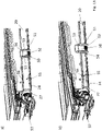
- the drawing shows a vehicle roof 10 which is a panoramic roof of a passenger car and has a front or bow-side transparent roof section 11 and a rear or rear-side transparent roof section 12 .
- the front transparent roof section 11 is formed by an adjustable cover element of a sliding roof system.
- the transparent roof sections 11 and 12 are framed by an opaque fixed roof section 13 and separated from one another by a fixed roof section 14 that is also opaque and extends in the transverse direction of the vehicle.
- the vehicle roof 10 has a roller blind arrangement 15, which comprises two roller blind units 16 and 17, of which the roller blind unit 16 is used for shading of the front transparent roof section 11 and the roller blind unit 17 for shading the rear transparent roof section 12 is used.
- the roller blind unit 16 has a roller blind web 18
- the roller blind unit 17 has a roller blind web 19 .
- the two roller blind webs 18 and 19 are each formed from an opaque, windable material and can be wound up in the area below the fixed roof section 14 extending in the transverse direction of the roof to form a roller blind roll 20 or 21 .
- the roller blind 18 and 19 each have a pull bow 22 or 23, which is arranged on the respective roller blind 18 or 19 on an edge facing away from the roller blind 20 or 21 .
- roller blind units 16 and 17 are of the same design in the present case, which is why the following description is essentially only based on the roller blind unit 16 assigned to the front transparent roof section 11 .
- the roller blind assembly 15 includes a bearing shell 24, which is connected from below to a roof frame 27, which is a roof-mounted support section and a pair of front guide rails or guide rail profiles 25A and 25B, which are arranged along lateral edges of the front transparent roof section 11, and a pair rear guide rails or guide rail profiles 26A and 26B, respectively, which are arranged along lateral edges of the rear transparent roof section 12.
- the bearing shell 24 forms a support plate or a roller blind pan for the roller blind units 16 and 17 and extends below the fixed roof section 14 in the transverse direction of the roof.
- the bearing shell 24 is provided with a fixing plate 28A or 28B at its edges, which are arranged on both sides in relation to the vertical longitudinal center plane of the roof, which can be screwed to a respective B-pillar of the relevant vehicle body. Furthermore, the bearing shell 24 forms run-off edges for the roller blind webs 18 and 19 on its edges running in the transverse direction of the roof.
- the roller blind units 16 and 17 each comprise bearing units 30 which are mirror-symmetrical to one another in relation to the vertical longitudinal center plane of the roof, via which the respective roller blind unit 16 or 17 is mounted on the one hand on the bearing shell 24 and on the other hand is connected to the respective guide rails 25A and 25B or 26A and 26B .
- the roller blind units 16 and 17 are not specified in each case shown winding shaft, which is rotatably mounted between the respective bearing units 30 and has a winding tube pretensioned by means of a winding spring, not shown in detail, in the winding direction of the respective roller blind web 18 or 19 .
- the bearing units 30 each have a bearing journal 32 which is formed on the inside of the respective bearing unit 30 facing the respective roller blind roll 20 or 21 .
- the storage units 30, one of which in the Figures 6 to 8 is shown on its own are each formed in two parts and include a bearing block 301 and a roller blind guide element 302.
- the bearing block 301 is fastened to the upper side of the bearing shell 24 by means of a fixing screw 303 which engages from below.
- the roller blind guide element 302 is inserted from the front into the bearing block 301 in the manner of a drawer in relation to the pull-out direction of the respective roller blind and is secured in a pre-assembly position by means of latching lugs 304 and 305 on the respective bearing block 301 .
- the bearing block 301 has a pin 306 on its underside, which engages in a slot 241 in the bearing shell 24 .
- the roller blind guide element 302 which is movably mounted in the respective bearing block 301 both in the vertical and transverse direction of the roof and in the longitudinal direction of the roof, has a guide section 307, which is pushed into the bearing block 301, and a front centering section 308, by means of which the roller blind guide element 302 is exactly opposite the roof frame 27 or the respective guide rail 25A, 25B, 26A or 26B can be positioned.
- the centering section 308 has at its top a positioning projection representing a centering rib 309 which, like the Figures 16a and 16b can be seen, engages from below in a channel 34 of the respective guide rail, which forms a receptacle of the support section. To make it easier for the centering rib 309 to dip into the channel 34, it has a flank on both sides that is designed as an insertion bevel 310.
- the centering rib 309 enables an exact positioning of the roller blind guide element 302 in relation to the respective guide rail 25A, 25B, 26A or 26B in the transverse direction of the roof.
- the guide section 307 has an end face 311 which, in the assembly position, rests flush against an end face of the relevant guide rail 25A, 25B, 26A or 26B.
- centering pins 312 are also formed in the area of the end face 311, which engage in channels of the respective guide rail profile 25A, 25B, 26A or 26B, which each form a centering recess fixed to the roof .
- a guide track 313 is formed on the guide section 307 of the blind guide element 302, which is aligned with a channel 35 of the respective guide rail 25A, 25B, 26A or 26B and in which a respective lateral guide band of the respective blind track 18 or 19 is guided.
- the guide track 313 is delimited at the top by a web 314, on the top of which a groove 315 is formed, which is interrupted by a latching lug 316, by means of which a pull bow slider 33 can be secured in a pre-assembled state on the roller blind guide element 302 of the respective storage unit 30.
- the roller blind guide elements 302 of the bearing units 30 also have a fixing bracket 317 on their front end facing away from the respective bearing block 301, which is provided with a screw hole 318, which is arranged on the side in the extension direction of the respective roller blind web 18 or 19, i.e on the end face of the respective roller blind guide element 302 is open and via which the respective roller blind guide element 302 is screwed to a respective guide rail 25A, 25B, 26A or 26B by means of a fixing screw 36 (cf. figure 17 ).
- roller blind guide elements 302 each have a recessed grip 319 on their underside.
- the roller blind guide elements 302 protrude beyond an edge of the bearing shell 24 in the extension direction of the relevant roller blind web 18 or 19, so that the recessed grip 319 can be gripped by a worker from below so that he can position the roller blind guide elements 302 in relation to the bearing blocks 301 can move in the direction of the fixing screws 36 that the screw holes 318 surround the fixing screws 36 like a fork and the end faces 311 at the strike corresponding end faces of the relevant guide rails 25A, 25B, 26A and 26B.
- the centering pins 312 then engage in corresponding channels in the guide rails.
- roller blind units 16 and 17 are each driven by a drive motor of a drive motor unit 68, which is arranged below a rear area of the opaque fixed roof section 13 and drives the drive cables 39, which are each coupled to a respective pull bow slider 33 via a coupling element 70.
- the coupling elements 70 of the drive cables 39 are hook-shaped in cross section, so that they each have a tongue 71 which is aligned parallel to the vertical longitudinal center plane of the roof and engages in a receptacle 72 which is formed in the respective pull bow slider 33.
- the tongue 71 dips into the receptacle 72 of the pull-up bow slider 33 from above when the modular roller blind arrangement 15 is moved up to the roof frame 27 .
- the tongue 71 has flanks 73 which are designed as chamfers and which interact with the chamfers 74 and 75 of the receptacle 72 of the pull bow slider 33, so that the tongue 70 is guided into it in a precisely positioned manner and without play.
- the bearing shell 24 of the blind assembly 15 is provided in the area between the two blind units 16 and 17 with two mounting clips 50, like the Figures 10 to 13 can be seen, are each locked in a rectangular recess 51 of the bearing shell 24 and has a substantially rectangular cross section.
- the mounting clips 50 each have first locking tabs 52 on the underside, which engage behind the bearing shell 24 .
- stops 53 are formed which protrude in the transverse direction and bear against the upper side of the bearing shell 24 .
- the mounting clips 50 have second latching lugs 53 on their flanks on both sides, which are offset by 90° with respect to the first latching lugs 52 and via which the mounting clips 50 can be held in a pre-assembly position (cf. figure 13b ) can be latched to the roof frame 27 from below.
- the mounting clips 50 which each have four locking tabs, each reach through a mounting recess 54 of the roof frame 27. In this pre-assembly position, fixing screws 55 engage with their free end faces in threads 56, which are formed on the roof frame 27 for fixing the roller blind arrangement 15.
- centering pins 57 pointing in the vertical direction of the roof are arranged on the upper side of the bearing shell 24 Figure 13b engage shown pre-assembly position and in their final position in corresponding centering recesses of the roof frame 27.
- the pull-out bow sliders 33 each have a connecting strap 60 for the guide strip of the relevant roller blind 18 or 19 and a slide rail 61 on their lower lateral edges, which enables the pull-out bow sliders 33 can run over the interface between the respective guide rail 25A, 25B, 26A or 26B and the respective roller blind guide element 302 in a noise-optimized manner during regular operation of the blind arrangement 15 when the respective blind web 18 or 19 is opened or wound up. This ensures that a maximum area of the respective roof section 11 or 12 can be released for viewing.
- the pull bow sliders 33 each have a spring element 62, which holds them with tension in the respective guide rail 25A, 25B, 26A or 26B.
- roller blind arrangement 15 described above is assembled in the manner described below.
- the roller blind arrangement 15 is assembled, ie the bearing shell 24 is provided with the roller blind units 16 and 17 , with the bearing blocks 301 of the bearing units 30 being screwed to the bearing shell 24 via the fixing screws 303 .
- the fixing plates 28A and 28B are attached.
- the mounting clips 50 are inserted into the recesses 51 and the centering pins 57 are screwed on by means of screws engaging from below.
- the blind arrangement 15 provided in this way is then moved up from below to the fixed roof section 14 extending in the transverse direction of the roof, with the mounting clips 50 in the Mounting recesses 54 of the roof frame 27 are locked and immerse the centering pins in corresponding centering recesses of the roof frame 27.
- the roller blind guide elements 302 are moved in the longitudinal direction of the guide rails relative to the bearing blocks 301 and relative to the bearing shell 24 until the end faces 311 strike the front sides of the guide rails and the screw holes 318 grip the fixing screws 36, for example by manually gripping the roller blind guide elements 302 in the area the recessed grips 319 or by engaging an assembly mandrel in a hole 320 on the underside of the respective roller blind guide element 302. The screws 36 are then tightened.
- roller blind guide elements 302 This results in an exact positioning of the roller blind guide elements 302 in relation to the roof frame 27 .
- the roller blind arrangement 15 can now be put into operation.
Landscapes
- Engineering & Computer Science (AREA)
- Mechanical Engineering (AREA)
- Structural Engineering (AREA)
- Architecture (AREA)
- Civil Engineering (AREA)
- Chemical & Material Sciences (AREA)
- Combustion & Propulsion (AREA)
- Transportation (AREA)
- Operating, Guiding And Securing Of Roll- Type Closing Members (AREA)
Description
- Die Erfindung betrifft ein Fahrzeugdach mit den Merkmalen des Oberbegriffs des Patentanspruchs 1.
- Ein derartiges Fahrzeugdach ist aus der Druckschrift
DE 10 2014 005 476 A1 bekannt. Dieses Fahrzeugdach umfasst zur Beschattung eines transparenten Dachabschnitts eine Rolloanordnung, die beidseits jeweils eine Lagereinheit aufweist, welche von oben an einem Dachrahmen fixiert ist, der eine Lagerschale für die Rolloeinheit bildet. Der Dachrahmen ist wiederum an einem dachfesten Trägerabschnitt des betreffenden Fahrzeugs fixiert. Die Montage des Dachrahmens an dem betreffenden Fahrzeug bzw. dem betreffenden Fahrzeugdach erfolgt zusammen mit der Rolloanordnung. Die Rolloanordnung muss also komplett vormontiert sein, bevor der Dachrahmen mit einem Fahrzeugrohbau verbunden wird. Da der Bauraum dann nicht mehr zugänglich wäre, kann die Rolloanordnung nicht nach der Montage des Daches an dem Fahrzeugrohbau montiert werden. Das DokumentEP 2 327 576 zeigt ebenfalls ein gattungsgemäßes Fahrzeugdach mit Rolloanordnung. - Der Erfindung liegt die Aufgabe zugrunde, ein Fahrzeugdach der einleitend genannten Gattung zu schaffen, bei dem die Rolloanordnung auch nachträglich, das heißt bei mit einem Karosserierohbau verbundenen Trägerabschnitt von unten montierbar ist und die Lagereinheiten dann in einfacher Weise gegenüber dem dachfesten Trägerabschnitt positioniert werden können.
- Diese Aufgabe ist erfindungsgemäß durch das Fahrzeugdach mit den Merkmalen des Patentanspruchs 1 gelöst.
- Das Fahrzeugdach nach der Erfindung umfasst also seitliche Lagereinheiten für die Rollobahn bzw. den Rollowickel, die jeweils zweigeteilt sind und einen fest mit der Lagerschale verbundenen Lagerbock und ein Rolloführungselement umfassen, das gegenüber dem Lagerbock beweglich ist bzw. schwimmend an diesem gelagert ist, bevor es positionsgenau an dem dachfesten Trägerabschnitt fixiert wird. Die Rolloeinheit ist über die seitlichen Lagereinheiten auf der Lagerschale befestigt. Die Lagerschale kann von unten an dem dachfesten Trägerabschnitt fixiert werden. Die Lagerschale, die als so genannte Rollowanne ausgebildet sein kann, stellt eine Montageplattform dar, die nach Art eines Moduls mit dem Fahrzeugdach verbindbar ist, und zwar auch, wenn das Fahrzeugdach schon an dem Fahrzeugrohbau fixiert ist. Damit lässt sich die Rolloanordnung modularisiert nachträglich und automatisierbar montieren. Dies ermöglicht es wiederum, die Rolloanordnung erst zu einem späteren Zeitpunkt an den jeweiligen Kundenwunsch anzupassen, beispielsweise hinsichtlich der Farbe der Rollobahn. Zudem kann die Rolloanordnung in einem Bereich des Fahrzeugdachs von unten an dieses herangeführt werden, welcher neben dem transparenten Dachabschnitt liegt. Damit wird durch die Rolloanordnung nicht der maximal zur Verfügung stehende Dachdurchsichtsbereich überdeckt. Die Lagerböcke der Lagereinheiten, über die die Rolloeinheit auf die Lagerschale aufgesetzt ist, dienen insbesondere zur Lagerung des Rollowickels. Eine Kopplung der Rolloeinheit an den Trägerabschnitt bzw. dachfeste Führungsschienen, die Bestandteil des dachfesten Trägerabschnitts sein können, erfolgt über die Rolloführungselemente der Lagereinheiten.
- Unter der Montagestellung ist vorliegend die Stellung des Rolloführungselements zu verstehen, die dem fertig am Dach montierten Zustand entspricht. Die Vormontagestellung ist die Stellung des Rollo führungselements, die dieses beispielsweise bei einem Schritt zur Befestigung der Lagerschale einnimmt.
- Die Lagereinheiten bzw. die Einzelteile der Lagereinheiten können jeweils als Kunststoff-Spritzgießteil ausgebildet sein. Die Lagerschale, die sich vorzugsweise in Dachquerrichtung erstreckt und ein Stanz-/Biege-Blechteil sein kann, ist insbesondere einstückig ausgebildet.
- Bei einer bevorzugten Ausführungsform des Fahrzeugdachs nach der Erfindung stehen die Rolloführungselemente jeweils in Ausziehrichtung der Rollobahn über einen Rand der Lagerschale vor. Damit können die Rolloführungselemente vor ihrer Fixierung an dem dachfesten Trägerabschnitt gegenüber den Lagerböcken verschoben werden, wenn die Lagerschale schon an dem dachfesten Trägerabschnitt fixiert ist, da sie von einem Werker von unten erreichbar sind.
- Zur Fixierung der Rolloführungselemente an dem dachfesten Trägerabschnitt sind diese vorzugsweise jeweils mit einem Schraubenloch versehen, das an einer in Ausziehrichtung der Rollobahn angeordneten Seite offen ist und über das das jeweilige Rolloführungselement mit dem dachfesten Trägerabschnitt verschraubt ist. Bei fixierter Lagerschale kann damit das Rolloführungselement gegenüber dem betreffenden Lagerbock so verschoben werden, dass das Schraubenloch nach Art einer Gabel über eine vormontierte Schraube geschoben wird, über die dann das Rolloführungselement an dem dachfesten Trägerabschnitt fixiert wird.
- Um die Verlagerung der Rolloführungselemente gegenüber den Lagerböcken zu erleichtern, können die Rollo führungselemente an ihrer Unterseite jeweils eine Griffmulde aufweisen.
- Bei der Rolloanordnung des Fahrzeugdachs nach der Erfindung handelt es sich vorzugsweise um ein seitengeführtes Rollo. Bei einer bevorzugten Ausführungsform weisen daher die Rollo führungselemente jeweils eine Zentrierbahn auf, in der ein seitliches Führungsband der Rollobahn geführt ist und die mit einem Kanal eines Führungsschienenprofils fluchtet, das Bestandteil des dachfesten Trägerabschnitts ist. Die Rolloführungselemente sind damit zumindest im weitesten Sinne als Fortsetzungen der Führungsschienenprofile ausgebildet.
- In der Regel ist die Rollobahn der Rolloanordnung mit einem Zugspriegel versehen, der an seinen beiden seitlichen Enden jeweils einen Zugspriegelgleiter aufweist. Vorzugsweise weisen daher die Rollo führungselemente jeweils auch eine Führungsbahn für jeweils einen Zugspriegelgleiter auf, welche mit einem Führungskanal eines Führungsschienenprofils fluchtet, das Bestandteil des Trägerabschnitts ist. Diese Führungsbahn kann die Führungsbahn umfassen, in der ein seitliches Führungsband der Rollobahn geführt ist.
- Um die Zugspriegelgleiter in einem Vormontagezustand, das heißt beim Montieren der Rolloanordnung bzw. dessen Lagerschale an dem dachfesten Trägerabschnitt die Zugspriegelgleiter verliersicher zu halten, weisen die Rolloführungsabschnitte vorzugsweise jeweils eine Rastnase oder Rastmulde auf, die den betreffenden Zugspriegelgleiter in dem Vormontagezustand an dem jeweiligen Rolloführungselement sichert und mit einem Rastgegenelement des jeweiligen Zugspriegelgleiters zusammenwirkt.
- Um Toleranzen in mehrere Raumrichtungen ausgleichen zu können, sind die Rolloführungselemente bei einer speziellen Ausführungsform des Fahrzeugdachs nach der Erfindung jeweils mit Spiel in mindestens zwei Raumrichtungen schwimmend in dem jeweiligen Lagerbock gelagert. Beispielsweise können die Rolloführungselemente vor ihrer Fixierung an dem dachfesten Trägerabschnitt in Ausziehrichtung der Rollobahn aus den Lagerböcken gezogen und in Dachquerrichtung versetzt werden.
- Beim Transport der Rolloanordnung, das heißt vor der Montage der Rolloanordnung an dem dachfesten Trägerabschnitt ist es zweckmäßig, dass sämtliche Elemente der Rolloanordnung verliersicher gehalten sind. Aus diesem Grunde ist bei einer speziellen Ausführungsform des Fahrzeugdachs nach der Erfindung für die Rolloführungselemente jeweils eine Rasteinrichtung vorgesehen, die diese in einem Vormontagezustand an dem jeweiligen Lagerbock sichert. Die Rasteinrichtung kann Rastnasen und/oder Rastmulden umfassen.
- Bei der Montage der Rolloanordnung an dem Trägerabschnitt ist es vorteilhaft, wenn schon beim Heranfahren eine möglichst präzise Vorpositionierung der Rolloführungselemente gegenüber dem Trägerabschnitt erreicht wird. Dies wird beispielsweise so realisiert, dass die Rollo führungselemente jeweils einen Positioniervorsprung aufweisen, der von unten in eine korrespondierende Aufnahme des Trägerabschnitts eingreift und der insbesondere als Zentrierrippe ausgebildet ist, die sich in Ausziehrichtung der Rollobahn erstreckt.
- Der Positioniervorsprung kann zudem mit mindestens einer Einführschräge versehen sein, die ein Verklemmen des Rolloführungselements beim Einfahren in den Trägerabschnitt verhindert.
- Zudem ist es vorteilhaft, wenn die Rolloführungselemente jeweils mindestens einen stirnseitigen Zentrierzapfen umfassen, der in eine dachfeste Zentrierausnehmung eingreift. Mit dem Zentrierzapfen kann eine präzise Montagelage des betreffenden Rolloführungselements gegenüber dem dachfesten Trägerabschnitt in Dachhochrichtung und/oder Dachquerrichtung erreicht werden. Die Zentrierausnehmung ist insbesondere von einem Kanal eines Führungsschienenprofils gebildet, an dem das betreffende Rolloführungselement in einer Montagestellung mit einer Stirnfläche anliegt. Die Stirnfläche bildet einen Anschlag für das Rolloführungselement, wodurch eine exakte Positionierung des betreffenden Rolloführungselements bzw. der Rolloeinheit in Ausziehrichtung der Rollobahn gewährleistet ist.
- Um die Zugspriegelgleiter über einen Antriebsmotor antreiben zu können, weisen diese jeweils vorzugsweise eine Aufnahme für ein Koppelelement eines jeweiligen Antriebskabels auf, das von dem Antriebsmotor angetrieben ist.
- Um bei der von unten erfolgenden Montage der Rolloanordnung und bei dem dachfesten Trägerabschnitt vormontierten Antriebskabeln eine selbsttätige Kopplung zwischen den Zugspriegelgleitern und den Antriebskabeln zu erreichen, sind die Aufnahmen der Zugspriegelgleiter vorzugsweise nach oben offen, wobei sie die Koppelelemente zumindest in Längsrichtung des betreffenden Führungsschienenprofils spielfrei aufnehmen.
- Die Kopplung zwischen den Koppelelementen und den Zugspriegelgleitern wird erleichtert, wenn die Aufnahmen und/oder die Koppelelemente jeweils Einführschrägen haben.
- Bei einer speziellen Ausführungsform des Fahrzeugdachs nach der Erfindung sind die Koppelelemente der Antriebskabel jeweils hakenförmig ausgebildet und mit einer Zunge versehen, die parallel zu der vertikalen Dachlängsmittelebene ausgerichtet ist.
- Die Lagereinheiten dienen vorzugsweise nicht nur zur Stoffzentrierung, das heißt zur Zentrierung der Rollobahn in Dachquerrichtung, sondern auch zur Lagerung des Rollowickels. Insbesondere können die Lagerböcke der Lagereinheiten jeweils einen Lagerzapfen für ein Wickelrohr, beispielsweise für eine mittels einer Wickelfeder vorgespannte Wickelwelle umfassen. Die Rolloeinheit kann aber auch wickelrohrfrei ausgebildet sein, wobei dann die seitlichen Führungsbänder vorzugsweise jeweils als Rollfeder ausgebildet sind und außerhalb der Führungsschienen ein Aufwickeln der Rollobahn bewirken.
- Zur Erleichterung der Montage der Rolloanordnung an dem dachfesten Trägerabschnitt ist die Lagerschale vorzugsweise mit mindestens einem Montageclip versehen, der diese in einer Vormontage an dem Trägerabschnitt hält und der vorzugsweise einen zumindest angenähert rechteckigen Querschnitt hat. Die Lagerschale kann über den Montageclip in einfacher Weise an dem Trägerabschnitt aufgehängt werden. Anschließend kann die Lagerschale über Schrauben oder sonstige Fixiermittel an dem dachfesten Trägerabschnitt gesichert werden bzw. weiter an den dachfesten Trägerabschnitt gezogen werden. Bei einer manuellen Montage der Rolloanordnung an den Trägerabschnitt wird durch den Montageclip den Werkern ermöglicht, ihre Hände frei zu bewegen.
- Vorzugsweise ist der Montageclip, der durch seine insbesondere rechteckige Form ein Verdrehen der Rolloanordnung gegenüber dem Trägerabschnitt in der Vormontagestellung verhindert, ein separates Bauteil, das mittels erster Rastlaschen in einer Ausnehmung der Lagerschale verrastet ist. Vor der Montage der Rolloanordnung an dem Trägerabschnitt wird die Lagerschale mit dem mindestens einen Montageclip versehen.
- Der Montageclip ist bei einer speziellen Ausführungsform des Fahrzeugdachs nach der Erfindung so ausgebildet, dass er in der Vormontagestellung mittels zweiter Rastlaschen in einer Montageausnehmung des Trägerabschnitts mit Spiel in Dachhochrichtung von unten verrastet. Der Abstand zwischen der Lagerschale und dem Trägerabschnitt ist in der Vormontagestellung vorzugsweise so gewählt, dass Fixierschrauben, mit denen die Lagerschale versehen ist, so in Gewinde eingreifen, dass eine Betätigung der Fixierschrauben dazu führt, dass diese direkt in Gewinde greifen und die Lagerschale so gegen den dachfesten Trägerabschnitt ziehen. Der Abstand zwischen dem Trägerabschnitt und der Lagerschale in der Vormontagestellung korrespondiert mit dem Spiel in Dachhochrichtung, das durch den Montageclip vorgegeben wird.
- Um eine positionsgenaue Montage der Lagerschale bzw. der Rolloanordnung an dem dachfesten Trägerabschnitt zu erleichtern, weist die Lagerschale bei einer bevorzugten Ausführungsform des Fahrzeugdachs nach der Erfindung mindestens einen Zentrierstift, vorzugsweise bezogen auf eine vertikale Dachlängsmittelebene beidseits jeweils mindestens einen Zentrierstift auf, der von unten in eine korrespondierende Zentrierausnehmung des dachfesten Trägerabschnitts eingreift und so die Rolloanordnung während der Montage an dem Trägerabschnitt ausrichtet.
- Um die Steifigkeit des betreffenden Fahrzeugs im Dachbereich zu erhöhen, kann die Lagerschale bezogen auf die vertikale Dachlängsmittelebene beidseits jeweils mit einem Fixierblech versehen sein, über das sie karosseriefest fixierbar ist. Beispielsweise werden die Fixierbleche im montierten Zustand mit B-Säulen des betreffenden Fahrzeugs verbunden. Die Fixierbleche stellen so genannte Crash-Bleche dar.
- Der Trägerabschnitt, an dem die Rolloanordnung bzw. die Lagerschale der Rolloanordnung in Einbaulage befestigt ist, kann von einem Rahmen eines Dachöffhungssystems gebildet sein. Der Rahmen kann Führungsschienen bzw. Führungsschienenprofile aufweisen, an welchen die Rollobahn der Rolloanordnung über seitliche Führungsbänder geführt ist.
- Die Lagerschale der Rolloanordnung kann eine Ablaufkante für die Rollobahn bilden und so eine Wölbung eines ausgezogenen Bereichs der Rollobahn vorgeben.
- Bei einem Fahrzeugdach mit zwei transparenten Dachabschnitten kann die Rolloanordnung zwei Rolloeinheiten umfassen, die auf der Lagerschale angeordnet sind und die gegensinnig ausziehbar sind.
- Die Erfindung hat auch ein Fahrzeugdach zum Gegenstand, das mindestens einen transparenten Dachabschnitt, einen dachfesten Trägerabschnitt und eine Rolloanordnung zur wahlweisen Abschattung oder zumindest teilweisen Freigabe des transparenten Dachabschnitts umfasst, die mindestens eine Rolloeinheit aufweist, die eine Rollobahn, die zu einem Rollowickel aufwickelbar ist, und bezogen auf eine vertikale Dachlängsmittelebene beidseits jeweils eine seitliche Lagereinheit umfasst. Der Rollowickel ist zwischen den beiden seitlichen Lagereinheiten angeordnet. Die Rolloanordnung umfasst eine Lagerschale, auf der die mindestens eine Rolloeinheit über die seitlichen Lagereinheiten befestigt ist und die von unten an dem mindestens einen Trägerabschnitt fixiert ist. Die Lagerschale, die sich insbesondere in Dachquerrichtung erstreckt und einstückig ausgebildet ist, ist mit mindestens einem Montageclip versehen, der sie in einer Vormontagestellung an dem Trägerabschnitt hält und der vorzugsweise einen eckigen, insbesondere zumindest angenähert rechteckigen Querschnitt hat.
- Es versteht sich, dass dieses Fahrzeugdach, das mit einer montagefreundlichen, von unten montierbaren Rolloanordnung versehen ist, sämtliche oben beschriebenen Merkmale jeweils separat oder in beliebiger Kombination aufweisen kann.
- Weitere Vorteile und vorteilhafte Ausgestaltungen des Gegenstandes der Erfindung sind der Beschreibung, der Zeichnung und den Patentansprüchen entnehmbar.
- Ein Ausführungsbeispiel eines Fahrzeugdachs nach der Erfindung ist in der Zeichnung schematisch vereinfacht dargestellt und wird in der nachfolgenden Beschreibung näher erläutert. Es zeigt:
- Figur 1
- eine Draufsicht auf ein Fahrzeugdach nach der Erfindung:
- Figur 2
- eine Unteransicht des Fahrzeugdachs;
- Figur 3
- eine perspektivische Draufsicht des Fahrzeugdachs;
- Figur 4
- eine Rolloanordnung des Fahrzeugdachs in einer perspektivischen Draufsicht;
- Figur 5
- eine Seitenansicht einer Lagerschale der Rolloanordnung mit einer Lagereinheit für eine Rollobahn;
- Figur 6
- eine perspektivische Draufsicht der Lagereinheit;
- Figur 7
- eine perspektivische Unteransicht der Lagereinheit;
- Figur 8
- eine Explosionsdarstellung der Lagereinheit;
- Figur 9
- eine perspektivische ausschnittsweise Unteransicht der Lagerschale mit einer Lagereinheit;
- Figur 10
- eine perspektivische Darstellung durch die Lagerschale und einen Montageclip;
- Figur 11
- eine perspektivische Draufsicht auf die Lagerschale im Bereich des Montageclips;
- Figur 12
- eine perspektivische Unteransicht der Lagerschale im Bereich des Montageclips;
- Figur 13a,
- b eine Vormontage der Rolloanordnung an einem dachfesten Trägerabschnitt;
- Figur 14a, b
- eine Kopplung eines Antriebskabels mit einem Zugspriegelgleiter der Rolloanordnung bei der Montage der Rolloanordnung;
- Figur 15a, b
- die Kopplung gemäß
Figur 14a, b in einem Längsschnitt durch die Rolloanordnung; - Figur 16a, b
- eine Positionierung einer der Lagereinheiten der Rolloanordnung bezüglich einer Führungsschiene bei der Montage der Rolloanordnung;
- Figur 17a, b
- eine Fixierung eines Rolloführungsabschnitts der Lagereinheiten an einer Führungsschiene; und
- Figur 18
- eine perspektivische Seitenansicht eines Zugspriegelgleiters der Rolloanordnung.
- In der Zeichnung ist ein Fahrzeugdach 10 dargestellt, das ein Panoramadach eines Personenkraftwagens ist und einen vorderen bzw. bugseitigen transparenten Dachabschnitt 11 und einen hinteren bzw. heckseitigen transparenten Dachabschnitt 12 aufweist. Der vordere transparente Dachabschnitt 11 ist von einem verstellbaren Deckelelement eines Schiebedachsystems gebildet. Die transparenten Dachabschnitte 11 und 12 sind von einem blickdichten Festdachabschnitt 13 umrahmt und durch einen sich in Fahrzeugquerrichtung erstreckenden ebenfalls blickdichten Festdachabschnitt 14 voneinander getrennt.
- Zum wahlweisen Abschatten oder zumindest teilweisen Freigeben der transparenten Dachabschnitte 11 und 12 weist das Fahrzeugdach 10 eine Rollo anordnung 15 auf, die zwei Rolloeinheiten 16 und 17 umfasst, von denen die Rolloeinheit 16 zur Abschattung des vorderen transparenten Dachabschnitts 11 und die Rolloeinheit 17 zum Abschatten des hinteren transparenten Dachabschnitts 12 dient. Hierzu weist die Rolloeinheit 16 eine Rollobahn 18 und die Rolloeinheit 17 eine Rollobahn 19 auf. Die beiden Rollobahnen 18 und 19 sind jeweils aus einem blickdichten, wickelbaren Stoff gebildet und in dem unterhalb des Festdachabschnitts 14 angeordneten, sich in Dachquerrichtung erstreckenden Bereich zu einem Rollowickel 20 bzw. 21 aufwickelbar. Zur Betätigung, das heißt zum Ausziehen oder Aufwickeln der Rollobahn 18 und 19 weisen die Rolloeinheiten 16 und 17 jeweils einen Zugspriegel 22 bzw. 23 auf, der an der jeweiligen Rollobahn 18 bzw. 19 an einem dem Rollowickel 20 bzw. 21 abgewandten Rand angeordnet ist.
- Die Rolloeinheiten 16 und 17 sind im vorliegenden Fall gleichartig ausgebildet, weswegen die nachfolgende Beschreibung im Wesentlichen nur anhand der dem vorderen transparenten Dachabschnitt 11 zugeordneten Rolloeinheit 16 erfolgt.
- Die Rolloanordnung 15 umfasst eine Lagerschale 24, welche von unten an einen Dachrahmen 27 angebunden ist, der einen dachfesten Trägerabschnitt darstellt und ein Paar vorderer Führungsschienen bzw. Führungsschienenprofile 25A und 25B, die entlang seitlicher Ränder des vorderen transparenten Dachabschnitts 11 angeordnet sind, und ein Paar hinterer Führungsschienen bzw. Führungsschienenprofile 26A bzw. 26B umfasst, die entlang seitlicher Ränder des hinteren transparenten Dachabschnitts 12 angeordnet sind. Die Lagerschale 24 bildet eine Tragplatte bzw. eine Rollowanne für die Rolloeinheiten 16 und 17 und erstreckt sich unterhalb des Festdachabschnitts 14 in Dachquerrichtung. Zudem ist die Lagerschale 24 an ihren bezogen auf die vertikale Dachlängsmittelebene beidseits angeordneten Rändern jeweils mit einem Fixierblech 28A bzw. 28B versehen, das mit einer jeweiligen B-Säule des betreffenden Fahrzeugaufbaus verschraubt werden kann. Ferner bildet die Lagerschale 24 an ihren in Dachquerrichtung verlaufenden Rändern Ablaufkanten für die Rollobahnen 18 und 19.
- Die Rolloeinheiten 16 und 17 umfassen jeweils bezogen auf die vertikale Dachlängsmittelebene spiegelsymmetrisch zueinander ausgebildete Lagereinheiten 30, über die die jeweilige Rolloeinheit 16 bzw. 17 einerseits auf der Lagerschale 24 montiert ist und andererseits an die jeweiligen Führungsschienen 25A und 25B bzw. 26A und 26B angebunden ist. Zudem weisen die Rollo einheiten 16 und 17 jeweils eine nicht näher dargestellte Wickelwelle auf, die zwischen den jeweiligen Lagereinheiten 30 drehbar gelagert ist und ein mittels einer nicht näher dargestellten Wickelfeder in Aufwickelrichtung der jeweiligen Rollobahn 18 bzw. 19 vorgespanntes Wickelrohr hat. Zur Lagerung der Wickelwelle weisen die Lagereinheiten 30 jeweils einen Lagerzapfen 32 auf, der an der dem jeweiligen Rollowickel 20 bzw. 21 zugewandten Innenseite der jeweiligen Lagereinheit 30 ausgebildet ist.
- Die Lagereinheiten 30, von denen eine in den
Figuren 6 bis 8 in Alleinstellung dargestellt ist, sind jeweils zweiteilig ausgebildet und umfassen einen Lagerbock 301 und ein Rolloführungselement 302. Der Lagerbock 301 ist mittels einer Fixierschraube 303, die von unten eingreift, an der Oberseite der Lagerschale 24 befestigt. Das Rolloführungselement 302 ist nach Art einer Schublade bezogen auf die Ausziehrichtung der jeweiligen Rollobahn von vorne in den Lagerbock 301 eingeschoben und in einer Vormontagestellung mittels Rastnasen 304 und 305 an dem jeweiligen Lagerbock 301 gesichert. - Zur exakten Positionierung des Lagerbocks 301 auf der Lagerschale 24 weist der Lagerbock 301 an seiner Unterseite einen Stift 306 auf, welcher in einen Schlitz 241 der Lagerschale 24 eingreift.
- Das Rolloführungselement 302, das sowohl in Dachhochrichtung und Dachquerrichtung als auch in Dachlängsrichtung beweglich in dem jeweiligen Lagerbock 301 gelagert ist, weist einen Führungsabschnitt 307, der in den Lagerbock 301 eingeschoben ist, und einen vorderen Zentrierabschnitt 308 auf, mittels dessen das Rolloführungselement 302 exakt gegenüber dem Dachrahmen 27 bzw. der jeweiligen Führungsschiene 25A, 25B, 26A oder 26B positioniert werden kann.
- Der Zentrierabschnitt 308 weist an seiner Oberseite eine einen Positioniervorsprung darstellende Zentrierrippe 309 auf, die, wie den
Figuren 16a und 16b zu entnehmen ist, von unten in einen Kanal 34 der jeweiligen Führungsschiene eingreift, der eine Aufnahme des Trägerabschnitts bildet. Um das Eintauchen der Zentrierrippe 309 in den Kanal 34 zu erleichtern, hat sie beidseits jeweils eine als Einführschräge 310 ausgestellte Flanke. Die Zentrierrippe 309 ermöglicht eine exakte Positionierung des Rolloführungselements 302 gegenüber der jeweiligen Führungsschiene 25A, 25B, 26A bzw. 26B in Dachquerrichtung. - Des Weiteren weist der Führungsabschnitt 307 eine Stirnfläche 311 auf, welche in der Montagestellung bündig an einer Stirnseite der betreffenden Führungsschiene 25A, 25B, 26A bzw. 26B anliegt. Um eine exakte Positionierung des eine Stoffzentrierung bereitstellendes Rolloführungselements 302, in Dachhochrichtung zu erreichen, sind im Bereich der Stirnfläche 311 des Weiteren Zentrierzapfen 312 ausgebildet, die in Kanäle des jeweiligen Führungsschienenprofils 25A, 25B, 26A bzw. 26B eingreifen, welche jeweils eine dachfeste Zentrierausnehmung bilden.
- An dem Führungsabschnitt 307 des Rolloführungselements 302 ist eine Führungsbahn 313 ausgebildet, welche mit einem Kanal 35 der jeweiligen Führungsschiene 25A, 25B, 26A bzw. 26B fluchtet und in der ein jeweiliges seitliches Führungsband der jeweiligen Rollobahn 18 bzw. 19 geführt ist. Die Führungsbahn 313 ist oben von einem Steg 314 begrenzt, an dessen Oberseite eine Nut 315 ausgebildet ist, welche von einer Rastnase 316 unterbrochen ist, mittels der ein Zugspriegelgleiter 33 in einem Vormontagezustand an dem Rolloführungselement 302 der jeweiligen Lagereinheit 30 gesichert werden kann.
- Die Rolloführungselemente 302 der Lagereinheiten 30 weisen des Weiteren an ihren vorderen, dem jeweiligen Lagerbock 301 abgewandten Ende eine Fixierlasche 317 auf, welche mit einem Schraubenloch 318 versehen ist, das an der in der Ausziehrichtung der jeweiligen Rollobahn 18 bzw. 19 angeordneten Seite, das heißt an der Stirnseite des jeweiligen Rollo führungselements 302 offen ist und über das das jeweilige Rollo führungselement 302 an einer jeweiligen Führungsschiene 25A, 25B, 26A bzw. 26B mittels einer Fixierschraube 36 verschraubt ist (vgl.
Figur 17 ). - Zudem weisen die Rollo führungselemente 302 an ihrer Unterseite jeweils eine Griffmulde 319 auf.
- Wie insbesondere den
Figuren 17a und 17b zu entnehmen ist, stehen die Rolloführungselemente 302 jeweils in Ausziehrichtung der betreffenden Rollobahn 18 bzw. 19 über einen Rand der Lagerschale 24 über, so dass die Griffmulde 319 für einen Werker von unten greifbar ist, so dass er die Rolloführungselemente 302 gegenüber den Lagerböcken 301 so in Richtung der Fixierschrauben 36 verschieben kann, dass die Schraubenlöcher 318 die Fixierschrauben 36 gabelartig umgreifen und die Stirnflächen 311 an den korrespondierenden Stirnseiten der betreffenden Führungsschienen 25A, 25B, 26A bzw. 26B anschlagen. Die Zentrierzapfen 312 greifen dann in entsprechende Kanäle der Führungsschienen ein. - Die Rolloeinheiten 16 und 17 sind jeweils mittels eines Antriebsmotors einer Antriebsmotoreinheit 68 angetrieben, die unterhalb eines heckseitigen Bereichs des blickdichten Festdachabschnitts 13 angeordnet ist und die Antriebskabel 39 antreibt, die jeweils über ein Koppelelement 70 mit einem jeweiligen Zugspriegelgleiter 33 gekoppelt sind.
- Wie insbesondere den
Figuren 14 und15 zu entnehmen ist, sind die Koppelelemente 70 der Antriebskabel 39 im Querschnitt hakenförmig ausgebildet, so dass sie jeweils eine Zunge 71 aufweisen, die parallel zu der vertikalen Dachlängsmittelebene ausgerichtet ist und in eine Aufnahme 72 eingreift, die in dem jeweiligen Zugspriegelgleiter 33 ausgebildet ist. - Wie ebenfalls den
Figuren 14 und15 zu entnehmen ist, taucht die Zunge 71 beim Heranfahren der modulartigen Rolloanordnung 15 an den Dachrahmen 27 von oben in die Aufnahme 72 des Zugspriegelgleiters 33 ein. Um Toleranzen hinsichtlich der Positionierung ausgleichen zu können, weist die Zunge 71 Flanken 73 auf, die als Einführschrägen ausgebildet sind und die mit Einführschrägen 74 und 75 der Aufnahme 72 des Zugspriegelgleiters 33 zusammenwirken, so dass die Zunge 70 positionsgenau und spielfrei in diese geführt wird. - Die Lagerschale 24 der Rolloanordnung 15 ist in dem Bereich zwischen den beiden Rolloeinheiten 16 und 17 mit zwei Montageclips 50 versehen, die, wie den
Figuren 10 bis 13 zu entnehmen ist, jeweils in einer rechteckigen Ausnehmung 51 der Lagerschale 24 verrastet sind und einen im Wesentlichen rechteckigen Querschnitt hat. An der Unterseite haben die Montageclips 50 jeweils erste Rastlaschen 52, die die Lagerschale 24 hintergreifen. Um die Montageclips 50 an der Lagerschale in Position zu halten, sind Anschläge 53 ausgebildet, die in Querrichtung vorstehen und an der Oberseite der Lagerschale 24 anliegen. Zudem weisen die Montageclips 50 an ihren beidseitigen Flanken zweite Rastlaschen 53 auf, die gegenüber den ersten Rastlaschen 52 um 90° versetzt sind und über die die Montageclips 50 in einer Vormontagestellung (vgl.Fig. 13b ) an dem Dachrahmen 27 von unten verrastet werden können. Hierbei durchgreifen die Montageclips 50, die also jeweils vier Rastlaschen aufweisen, jeweils eine Montageausnehmung 54 des Dachrahmens 27. In dieser Vormontagestellung greifen Fixierschrauben 55 mit ihren freien Stirnseiten in Gewinde 56 ein, die an dem Dachrahmen 27 zur Fixierung der Rolloanordnung 15 ausgebildet sind. - Des Weiteren sind an der Lagerschale 24 oberseitig in Dachhochrichtung weisende Zentrierstifte 57 angeordnet, die in der in
Figur 13b dargestellten Vormontagestellung und auch in ihrer Endstellung in korrespondierende Zentrierausnehmungen des Dachrahmens 27 eingreifen. - Wie
Figur 18 zu entnehmen ist, weisen die Zugspriegelgleiter 33 neben der Aufnahme 72 für das betreffende Koppelelement 70 jeweils eine Anbindungslasche 60 für das Führungsband der betreffenden Rollobahn 18 bzw. 19 sowie an ihren unteren seitlichen Rändern jeweils eine Gleitschiene 61 auf, die es ermöglicht, dass die Zugspriegelgleiter 33 im regulären Betrieb der Rolloanordnung 15 beim Öffnen bzw. Aufwickeln der jeweiligen Rollobahn 18 bzw. 19 die Schnittstelle zwischen der jeweiligen Führungsschiene 25A, 25B, 26A bzw. 26B und dem jeweiligen Rolloführungselement 302 geräuschoptimiert überfahren kann. Damit ist gewährleistet, dass eine maximale Fläche des jeweiligen Dachabschnitts 11 bzw. 12 zur Durchsicht freigegeben werden kann. Zudem weisen die Zugspriegelgleiter 33 jeweils ein Federelement 62 auf, das sie jeweils mit Spannung in der jeweiligen Führungsschiene 25A, 25B, 26A bzw. 26B hält. - Die Montage der vorstehend beschriebenen Rolloanordnung 15 erfolgt in nachfolgend beschriebener Weise.
- In einem ersten Montageschritt wird die Rolloanordnung 15 zusammengesetzt, das heißt die Lagerschale 24 wird mit den Rolloeinheiten 16 und 17 versehen, wobei die Lagerböcke 301 der Lagereinheiten 30 über die Fixierschrauben 303 mit der Lagerschale 24 verschraubt werden. Zudem werden die Fixierbleche 28A und 28B befestigt. Des Weiteren werden die Montageclips 50 in die Ausnehmungen 51 eingesteckt und die Zentrierstifte 57 mittels von unten eingreifender Schrauben verschraubt. Die so bereitgestellte Rolloanordnung 15 wird dann von unten an den sich in Dachquerrichtung erstreckenden Festdachabschnitt 14 herangefahren, wobei die Montageclips 50 in den Montageausnehmungen 54 des Dachrahmens 27 verrastet werden und die Zentrierstifte in korrespondierende Zentrierausnehmungen des Dachrahmens 27 eintauchen. Anschließend werden die Fixierschrauben 55 angezogen, wodurch die Lagerschale 24 gegen den Dachrahmen 27 gezogen wird. Gleichzeitig tauchen die Zungen 71 der Koppelelemente 70, die in eine Montagestellung gebracht sind, in die Aufnahmen 72 der Zugspriegelgleiter 33 ein. Zudem tauchen die Zentrierrippen 309 der Rolloführungselemente 302 der Lagereinheiten 30 in die Kanäle 34 der Führungsschienen 25A, 25B, 26A und 26B ein, wodurch eine Positionierung bzw. Zentrierung der Rolloführungselemente 302 in Dachquerrichtung erfolgt (vgl.
Figuren 16a und b ). - In einem nachfolgenden Montageschritt werden die Rolloführungselemente 302 in Führungsschienenlängsrichtung soweit gegenüber den Lagerböcken 301 und gegenüber der Lagerschale 24 verfahren, bis die Stirnflächen 311 an den Stirnseiten der Führungsschienen anschlagen und die Schraubenlöcher 318 die Fixierschrauben 36 umgreifen, beispielsweise durch manuelles Greifen der Rolloführungselemente 302 im Bereich der Griffmulden 319 oder durch Eingreifen eines Montagedorns in ein Loch 320 an der Unterseite des jeweiligen Rolloführungselements 302. Anschließend werden die Schrauben 36 angezogen.
- Damit liegt eine exakte Positionierung der Rolloführungselemente 302 gegenüber dem Dachrahmen 27 vor. Die Rolloanordnung 15 kann nun in Betrieb genommen werden.
-
- 10
- Fahrzeugdach
- 11
- Dachabschnitt
- 12
- Dachabschnitt
- 13
- Festdachabschnitt
- 14
- Festdachabschnitt
- 15
- Rolloanordnung
- 16
- Rolloeinheit
- 17
- Rolloeinheit
- 18
- Rollobahn
- 19
- Rollobahn
- 20
- Rollowickel
- 21
- Rollowickel
- 22
- Zugspriegel
- 23
- Zugspriegel
- 24
- Lagerschale
- 25A, B
- Führungsschiene
- 26A, B
- Führungsschiene
- 27
- Dachrahmen
- 28A, B
- Fixierblech
- 30
- Lagereinheit
- 32
- Lagerzapfen
- 33
- Zugspriegelgleiter
- 34
- Kanal
- 35
- Kanal
- 35
- Fixierschraube
- 39
- Antriebskabel
- 50
- Montageclip
- 51
- Ausnehmung
- 52
- Rastlasche
- 53
- Rastlasche
- 54
- Montageausnehmung
- 55
- Fixierschraube
- 56
- Gewinde
- 57
- Zentrierstift
- 60
- Anbindungslasche
- 61
- Gleitschiene
- 62
- Federelement
- 68
- Antriebsmotoreinheit
- 70
- Koppelelement
- 71
- Zunge
- 72
- Aufnahme
- 73
- Flanke
- 74
- Einführschräge
- 75
- Einführschräge
- 241
- Schlitz
- 301
- Lagerbock
- 302
- Rolloführungselement
- 303
- Fixierlasche
- 304
- Rastnase
- 305
- Rastnase
- 306
- Stift
- 307
- Führungsabschnitt
- 308
- Zentrierabschnitt
- 309
- Zentrierrippe
- 310
- Einführschräge
- 311
- Stirnfläche
- 312
- Zentrierzapfen
- 313
- Führungsbahn
- 314
- Steg
- 315
- Nut
- 316
- Rastnase
- 317
- Fixierlasche
- 318
- Schraubenloch
- 319
- Griffmulde
- 320
- Loch
Claims (15)
- Fahrzeugdach, umfassend mindestens einen transparenten Dachabschnitt (11, 12), einen dachfesten Trägerabschnitt und eine Rolloanordnung (15) zur wahlweisen Abschattung oder zumindest teilweisen Freigabe des transparenten Dachabschnitts (11, 12), die mindestens eine Rolloeinheit (16, 17) aufweist, die eine Rollobahn (18, 19), die zu einem Rollowickel (20, 21) aufwickelbar ist, und bezogen auf eine vertikale Dachlängsmittelebene beidseits jeweils eine seitliche Lagereinheit (30) umfasst, wobei der Rollowickel (20, 21) zwischen den beiden seitlichen Lagereinheiten (30) angeordnet ist und die Rolloanordnung (15) eine Lagerschale (24) umfasst, auf der die mindestens eine Rolloeinheit (16, 17) über die seitlichen Lagereinheiten (30) befestigt ist und die von unten an dem mindestens einen Trägerabschnitt fixiert ist, dadurch gekennzeichnet, dass die Lagereinheiten (30) jeweils einen Lagerbock (301), der an der Lagerschale (24) fixiert ist, und ein Rolloführungselement (302) umfassen, das in einer Vormontagestellung gegenüber dem Lagerbock (301) verlagerbar ist und in einer Montagestellung an dem dachfesten Trägerabschnitt fixiert ist.
- Fahrzeugdach nach Anspruch 1, dadurch gekennzeichnet, dass die Rolloführungselemente (302) jeweils in Ausziehrichtung der Rollobahn (18, 19) über einen Rand der Lagerschale (24) vorstehen.
- Fahrzeugdach nach Anspruch 1 oder 2, dadurch gekennzeichnet, dass die Rolloführungselemente (302) jeweils ein Schraubenloch (318) aufweisen, das an einer in Ausziehrichtung der Rollobahn (18, 19) angeordneten Seite offen ist und über das das jeweilige Rolloführungselement (302) mit dem dachfesten Trägerabschnitt verschraubt ist.
- Fahrzeugdach nach einem der Ansprüche 1 bis 3, dadurch gekennzeichnet, dass die Rolloführungselemente (302) jeweils an ihrer Unterseite eine Griffmulde (319) aufweisen.
- Fahrzeugdach nach einem der Ansprüche 1 bis 4, dadurch gekennzeichnet, dass die Rolloführungselemente (302) jeweils eine Zentrierbahn (313) aufweisen, in dem ein seitliches Führungsband der Rollobahn (18, 19) geführt ist und die mit einem Kanal eines Führungsschienenprofils (25A, 25B, 26A, 26B) fluchtet, das Bestandteil des Trägerabschnitts ist.
- Fahrzeugdach nach einem der Ansprüche 1 bis 5, dadurch gekennzeichnet, dass die Rolloführungselemente (302) jeweils eine Führungsbahn (34) für einen Zugspriegelgleiter (33) haben, die mit einem Führungskanal (35) eines Führungsschienenprofils (25A, 25B, 26A, 26B) fluchtet, das Bestandteil des Trägerabschnitts ist, wobei die Rolloführungselemente (302) vorzugsweise jeweils eine Rastnase (316) aufweisen, die den betreffenden Zugspriegelgleiter (33) in einem Vormontagezustand an dem jeweiligen Rolloführungselement (302) hält.
- Fahrzeugdach nach einem der Ansprüche 1 bis 6, dadurch gekennzeichnet, dass die Rolloführungselemente (302) jeweils mit Spiel in mindestens zwei Raumrichtungen in dem jeweiligen Lagerbock (301) gelagert sind.
- Fahrzeugdach nach einem der Ansprüche 1 bis 7, dadurch gekennzeichnet, dass die Rolloführungselemente (302) in einem Vormontagezustand mittels einer Rasteinrichtung (304, 305) in dem jeweiligen Lagerbock (301) gesichert sind.
- Fahrzeugdach nach einem der Ansprüche 1 bis 8, dadurch gekennzeichnet, dass die Rolloführungselemente (302) jeweils einen Positioniervorsprung aufweisen, der von unten in eine korrespondierende Aufnahme des Trägerabschnitts eingreift und der insbesondere als Zentrierrippe (309) ausgebildet ist, die sich in Ausziehrichtung der Rollobahn (18, 19) erstreckt.
- Fahrzeugdach nach einem der Ansprüche 1 bis 9, dadurch gekennzeichnet, dass die Rolloführungselemente (302) jeweils mindestens einen stirnseitigen Zentrierzapfen (312) umfassen, der in eine dachfeste Zentrierausnehmung eingreift, wobei die Zentrierausnehmung vorzugsweise von einem Führungsschienenprofil (25A, 25B, 26A, 26B) gebildet ist, an dem das betreffende Rolloführungselement (302) in einer Montagestellung mit einer Stirnfläche (311) anliegt.
- Fahrzeugdach nach einem der Ansprüche 1 bis 10, dadurch gekennzeichnet, dass Zugspriegelgleiter (33) vorgesehen sind, die jeweils eine Aufnahme (72) für ein Koppelelement (70) eines jeweiligen Antriebskabels (39) aufweisen, das von einem Antriebsmotor angetrieben ist, wobei die Aufnahme (72) vorzugsweise nach oben offen ist und das Koppelelement (70) in Längsrichtung des betreffenden Führungsschienenprofils (25A, 25B, 26A, 26B) spielfrei aufnimmt, wobei die Aufnahmen (72) vorzugsweise jeweils Einführschrägen (74, 75) für das jeweilige Koppelelement (70) haben, und wobei die Koppelelemente (70) der Antriebskabel (39) vorzugsweise jeweils einen hakenförmigen Querschnitt haben und jeweils eine Zunge (71) umfassen, die parallel zu der vertikalen Dachlängsmittelebene ausgerichtet ist.
- Fahrzeugdach nach einem der Ansprüche 1 bis 11, dadurch gekennzeichnet, dass die Lagerböcke (301) jeweils einen Lagerzapfen (32) für ein Wickelrohr umfassen.
- Fahrzeugdach nach einem der Ansprüche 1 bis 12, dadurch gekennzeichnet, dass die Lagerschale (24) mit mindestens einem Montageclip (50) versehen ist, der sie in einer Vormontagestellung an dem Trägerabschnitt hält und der vorzugsweise einen rechteckigen Querschnitt hat, wobei der Montageclip (50) vorzugsweise in einer Ausnehmung (51) der Lagerschale (24) verrastet ist, und wobei der Montageclip (50) vorzugsweise in der Vormontagestellung in einer Montageausnehmung (54) des Trägerabschnitts mit Spiel in Dachhochrichtung von unten verrastet ist.
- Fahrzeugdach nach einem der Ansprüche 1 bis 13, dadurch gekennzeichnet, dass der Trägerabschnitt von einem Rahmen eines Dachöffnungssystems gebildet ist.
- Fahrzeugdach nach einem der Ansprüche 1 bis 14, dadurch gekennzeichnet, dass die Rolloanordnung (15) zwei Rolloeinheiten (16, 17) umfasst, die auf der Lagerschale (24) angeordnet sind.
Applications Claiming Priority (2)
| Application Number | Priority Date | Filing Date | Title |
|---|---|---|---|
| DE102018108354.8A DE102018108354B4 (de) | 2018-04-09 | 2018-04-09 | Fahrzeugdach, umfassend eine Rolloanordnung mit Lagereinheiten für Rollobahn |
| PCT/EP2019/053959 WO2019197071A1 (de) | 2018-04-09 | 2019-02-18 | Fahrzeugdach, umfassend eine rolloanordnung mit lagereinheiten für rollobahn |
Publications (2)
| Publication Number | Publication Date |
|---|---|
| EP3774419A1 EP3774419A1 (de) | 2021-02-17 |
| EP3774419B1 true EP3774419B1 (de) | 2022-07-13 |
Family
ID=65685292
Family Applications (1)
| Application Number | Title | Priority Date | Filing Date |
|---|---|---|---|
| EP19708956.8A Active EP3774419B1 (de) | 2018-04-09 | 2019-02-18 | Fahrzeugdach, umfassend eine rolloanordnung mit lagereinheiten für rollobahn |
Country Status (5)
| Country | Link |
|---|---|
| US (1) | US10974579B2 (de) |
| EP (1) | EP3774419B1 (de) |
| CN (1) | CN112041183B (de) |
| DE (1) | DE102018108354B4 (de) |
| WO (1) | WO2019197071A1 (de) |
Families Citing this family (6)
| Publication number | Priority date | Publication date | Assignee | Title |
|---|---|---|---|---|
| DE102018205683B4 (de) * | 2018-04-13 | 2024-02-29 | Bayerische Motoren Werke Aktiengesellschaft | Dachsystem für ein fahrzeug, fahrzeug mit einem solchen dachsystem, dachelement und herstellungsverfahren |
| US11904670B2 (en) | 2021-02-04 | 2024-02-20 | Mytop Ip, Llc | Sliding soft-top convertible roof |
| DE102021206022B4 (de) | 2021-06-14 | 2025-05-28 | Bos Gmbh & Co. Kg | Beschattungsvorrichtung für einen Fahrzeuginnenraum eines Kraftfahrzeugs |
| EP4180254B1 (de) * | 2021-11-10 | 2025-05-07 | Inalfa Roof Systems Group B.V. | Rolloanordnung |
| GB2612810B (en) * | 2021-11-12 | 2024-03-20 | Jaguar Land Rover Ltd | Blind mounting apparatus and method |
| DE102023125315B4 (de) | 2023-09-19 | 2025-07-03 | Webasto SE | Fahrzeugdach mit Lagereinheiten für Wickelwelle |
Family Cites Families (14)
| Publication number | Priority date | Publication date | Assignee | Title |
|---|---|---|---|---|
| DE3607725A1 (de) * | 1986-03-08 | 1987-09-17 | Webasto Werk Baier Kg W | Fahrzeugdach |
| JPH0428814Y2 (de) * | 1986-04-22 | 1992-07-14 | ||
| JP2518113B2 (ja) * | 1991-05-28 | 1996-07-24 | 豊田合成株式会社 | クリップ付成形品の製造方法 |
| DE102004020337B4 (de) | 2004-01-13 | 2007-06-21 | Webasto Ag | Fahrzeugdach mit einer Rolloanordnung |
| JP5219075B2 (ja) * | 2008-08-29 | 2013-06-26 | トヨタ車体株式会社 | 自動車のルーフ構造 |
| DE102011007004B8 (de) | 2011-04-07 | 2013-01-10 | Bos Gmbh & Co. Kg | Rollobaueinheit für ein Kraftfahrzeug |
| DE102011113207B4 (de) * | 2011-09-08 | 2014-07-03 | Webasto Ag | Fahrzeugrolloanordnung und Fahrzeugdach |
| KR101233770B1 (ko) | 2012-06-21 | 2013-02-15 | (주)베바스토동희 홀딩스 | 파노라마 선루프용 롤러 블라인드 장치 |
| DE102014005476A1 (de) | 2014-04-15 | 2015-10-15 | Webasto SE | Rollovorrichtung an einem Fahrzeugdach |
| EP3100883B1 (de) * | 2015-06-01 | 2018-02-28 | Inalfa Roof Systems Group B.V. | Rolloanordnung und offene dachkonstruktion für ein damit ausgestattetes fahrzeug |
| DE102015109862B4 (de) | 2015-06-19 | 2025-04-10 | Webasto SE | Fahrzeugdach mit Rolloanordnung |
| JP6517646B2 (ja) | 2015-09-24 | 2019-05-22 | アイシン精機株式会社 | シェード装置 |
| DE102016111695A1 (de) | 2016-06-27 | 2017-12-28 | Webasto SE | Rolloanordnung für eine Fahrzeugkarosserie und Verfahren zum Zusammenbau der Rolloanordnung |
| DE102016125284B4 (de) | 2016-12-21 | 2018-07-05 | Webasto SE | Fahrzeugdach mit Trägerabschnitt und Rolloanordnung |
-
2018
- 2018-04-09 DE DE102018108354.8A patent/DE102018108354B4/de active Active
-
2019
- 2019-02-18 EP EP19708956.8A patent/EP3774419B1/de active Active
- 2019-02-18 US US16/981,829 patent/US10974579B2/en active Active
- 2019-02-18 WO PCT/EP2019/053959 patent/WO2019197071A1/de not_active Ceased
- 2019-02-18 CN CN201980024376.7A patent/CN112041183B/zh active Active
Also Published As
| Publication number | Publication date |
|---|---|
| DE102018108354A1 (de) | 2019-10-10 |
| CN112041183A (zh) | 2020-12-04 |
| US20210046810A1 (en) | 2021-02-18 |
| CN112041183B (zh) | 2022-06-07 |
| WO2019197071A1 (de) | 2019-10-17 |
| US10974579B2 (en) | 2021-04-13 |
| EP3774419A1 (de) | 2021-02-17 |
| DE102018108354B4 (de) | 2022-02-24 |
Similar Documents
| Publication | Publication Date | Title |
|---|---|---|
| EP3774419B1 (de) | Fahrzeugdach, umfassend eine rolloanordnung mit lagereinheiten für rollobahn | |
| EP3558732B1 (de) | Fahrzeugdach mit trägerabschnitt und rolloanordnung | |
| DE102015109862B4 (de) | Fahrzeugdach mit Rolloanordnung | |
| DE102008036839B4 (de) | Scheibenglasbefestigung für bewegliches Fahrzeugfenster | |
| DE102011018151A1 (de) | Baugruppe für ein öffnungsfähiges Schiebedach | |
| DE102012025392B3 (de) | Abdeckvorrichtung für ein mit einem Schließkeilmodul in eine die Verbindung einer Fahrzeugtüre mit einem Seitenwandrahmen einer Fahrzeugkarosserie bewirkende lösbare Kopplung bringbares Haltebackenmodul | |
| WO2013120699A1 (de) | Beschattungsanordnung für ein fahrzeug mit zwei beschattungseinheiten und verfahren zur montage einer beschattungsanordnung | |
| EP3427984A1 (de) | Schutzvorrichtung für einen fahrzeuginnenraum | |
| DE102005021585A1 (de) | Gleitstück für einen Fensterheber und damit ausgestatteter Fahrzeugfensterheber | |
| DE102005056662B4 (de) | Einrichtung zum Befestigen eines Dachgepäckträgers | |
| EP3142878B1 (de) | Rolloanordnung mit seitenführung | |
| DE3522047C2 (de) | ||
| EP1348585B1 (de) | Verfahrbarer Deckel für Fahrzeugdach sowie Schiebehebedach-Modul | |
| DE102008017074B3 (de) | Deckelelementträger | |
| EP1071572B1 (de) | Verstellvorrichtung für ein multispoilerdach für fahrzeuge | |
| DE10048981A1 (de) | Öffnungsfähiges Fahrzeugdach | |
| DE102021206022A1 (de) | Beschattungsvorrichtung für einen Fahrzeuginnenraum eines Kraftfahrzeugs | |
| DE102007002857B4 (de) | Rolloanordnung mit Führungselement | |
| DE102018116227B4 (de) | Mehrteiliger Rahmen für ein Fahrzeug-Schiebedach oder Fahrzeug-Schiebehebedach und Verfahren zur Montage eines mehrteiligen Rahmens | |
| DE102021006594A1 (de) | Rolloanordnung mit Zugspriegel und Antriebskabeln | |
| DE102021114037B4 (de) | Festdachelement mit Führungsschiene und Gleiter | |
| DE102011055196B4 (de) | Abdeckeinrichtung | |
| DE102021124555B4 (de) | Rolloanordnung mit Zugspriegel und Antriebskabeln | |
| DE202007008049U1 (de) | Führungsbaugruppe eines Kraftfahrzeugfensterhebers | |
| DE102023002359A1 (de) | Fahrzeug |
Legal Events
| Date | Code | Title | Description |
|---|---|---|---|
| STAA | Information on the status of an ep patent application or granted ep patent |
Free format text: STATUS: UNKNOWN |
|
| STAA | Information on the status of an ep patent application or granted ep patent |
Free format text: STATUS: THE INTERNATIONAL PUBLICATION HAS BEEN MADE |
|
| PUAI | Public reference made under article 153(3) epc to a published international application that has entered the european phase |
Free format text: ORIGINAL CODE: 0009012 |
|
| STAA | Information on the status of an ep patent application or granted ep patent |
Free format text: STATUS: REQUEST FOR EXAMINATION WAS MADE |
|
| 17P | Request for examination filed |
Effective date: 20200916 |
|
| AK | Designated contracting states |
Kind code of ref document: A1 Designated state(s): AL AT BE BG CH CY CZ DE DK EE ES FI FR GB GR HR HU IE IS IT LI LT LU LV MC MK MT NL NO PL PT RO RS SE SI SK SM TR |
|
| AX | Request for extension of the european patent |
Extension state: BA ME |
|
| DAV | Request for validation of the european patent (deleted) | ||
| DAX | Request for extension of the european patent (deleted) | ||
| GRAP | Despatch of communication of intention to grant a patent |
Free format text: ORIGINAL CODE: EPIDOSNIGR1 |
|
| STAA | Information on the status of an ep patent application or granted ep patent |
Free format text: STATUS: GRANT OF PATENT IS INTENDED |
|
| INTG | Intention to grant announced |
Effective date: 20211116 |
|
| GRAJ | Information related to disapproval of communication of intention to grant by the applicant or resumption of examination proceedings by the epo deleted |
Free format text: ORIGINAL CODE: EPIDOSDIGR1 |
|
| STAA | Information on the status of an ep patent application or granted ep patent |
Free format text: STATUS: REQUEST FOR EXAMINATION WAS MADE |
|
| RBV | Designated contracting states (corrected) |
Designated state(s): AL AT BE BG CH CY CZ DK EE ES FI FR GB GR HR HU IE IS IT LI LT LU LV MC MK MT NL NO PL PT RO RS SE SI SK SM TR |
|
| REG | Reference to a national code |
Ref country code: DE Ref legal event code: R108 |
|
| INTC | Intention to grant announced (deleted) | ||
| GRAP | Despatch of communication of intention to grant a patent |
Free format text: ORIGINAL CODE: EPIDOSNIGR1 |
|
| STAA | Information on the status of an ep patent application or granted ep patent |
Free format text: STATUS: GRANT OF PATENT IS INTENDED |
|
| GRAS | Grant fee paid |
Free format text: ORIGINAL CODE: EPIDOSNIGR3 |
|
| GRAA | (expected) grant |
Free format text: ORIGINAL CODE: 0009210 |
|
| STAA | Information on the status of an ep patent application or granted ep patent |
Free format text: STATUS: THE PATENT HAS BEEN GRANTED |
|
| INTG | Intention to grant announced |
Effective date: 20220531 |
|
| AK | Designated contracting states |
Kind code of ref document: B1 Designated state(s): AL AT BE BG CH CY CZ DK EE ES FI FR GB GR HR HU IE IS IT LI LT LU LV MC MK MT NL NO PL PT RO RS SE SI SK SM TR |
|
| REG | Reference to a national code |
Ref country code: CH Ref legal event code: EP |
|
| REG | Reference to a national code |
Ref country code: AT Ref legal event code: REF Ref document number: 1504103 Country of ref document: AT Kind code of ref document: T Effective date: 20220815 |
|
| REG | Reference to a national code |
Ref country code: IE Ref legal event code: FG4D Free format text: LANGUAGE OF EP DOCUMENT: GERMAN |
|
| REG | Reference to a national code |
Ref country code: LT Ref legal event code: MG9D |
|
| PG25 | Lapsed in a contracting state [announced via postgrant information from national office to epo] |
Ref country code: SE Free format text: LAPSE BECAUSE OF FAILURE TO SUBMIT A TRANSLATION OF THE DESCRIPTION OR TO PAY THE FEE WITHIN THE PRESCRIBED TIME-LIMIT Effective date: 20220713 Ref country code: RS Free format text: LAPSE BECAUSE OF FAILURE TO SUBMIT A TRANSLATION OF THE DESCRIPTION OR TO PAY THE FEE WITHIN THE PRESCRIBED TIME-LIMIT Effective date: 20220713 Ref country code: PT Free format text: LAPSE BECAUSE OF FAILURE TO SUBMIT A TRANSLATION OF THE DESCRIPTION OR TO PAY THE FEE WITHIN THE PRESCRIBED TIME-LIMIT Effective date: 20221114 Ref country code: NO Free format text: LAPSE BECAUSE OF FAILURE TO SUBMIT A TRANSLATION OF THE DESCRIPTION OR TO PAY THE FEE WITHIN THE PRESCRIBED TIME-LIMIT Effective date: 20221013 Ref country code: NL Free format text: LAPSE BECAUSE OF FAILURE TO SUBMIT A TRANSLATION OF THE DESCRIPTION OR TO PAY THE FEE WITHIN THE PRESCRIBED TIME-LIMIT Effective date: 20220713 Ref country code: LV Free format text: LAPSE BECAUSE OF FAILURE TO SUBMIT A TRANSLATION OF THE DESCRIPTION OR TO PAY THE FEE WITHIN THE PRESCRIBED TIME-LIMIT Effective date: 20220713 Ref country code: LT Free format text: LAPSE BECAUSE OF FAILURE TO SUBMIT A TRANSLATION OF THE DESCRIPTION OR TO PAY THE FEE WITHIN THE PRESCRIBED TIME-LIMIT Effective date: 20220713 Ref country code: FI Free format text: LAPSE BECAUSE OF FAILURE TO SUBMIT A TRANSLATION OF THE DESCRIPTION OR TO PAY THE FEE WITHIN THE PRESCRIBED TIME-LIMIT Effective date: 20220713 Ref country code: ES Free format text: LAPSE BECAUSE OF FAILURE TO SUBMIT A TRANSLATION OF THE DESCRIPTION OR TO PAY THE FEE WITHIN THE PRESCRIBED TIME-LIMIT Effective date: 20220713 |
|
| PG25 | Lapsed in a contracting state [announced via postgrant information from national office to epo] |
Ref country code: PL Free format text: LAPSE BECAUSE OF FAILURE TO SUBMIT A TRANSLATION OF THE DESCRIPTION OR TO PAY THE FEE WITHIN THE PRESCRIBED TIME-LIMIT Effective date: 20220713 Ref country code: IS Free format text: LAPSE BECAUSE OF FAILURE TO SUBMIT A TRANSLATION OF THE DESCRIPTION OR TO PAY THE FEE WITHIN THE PRESCRIBED TIME-LIMIT Effective date: 20221113 Ref country code: HR Free format text: LAPSE BECAUSE OF FAILURE TO SUBMIT A TRANSLATION OF THE DESCRIPTION OR TO PAY THE FEE WITHIN THE PRESCRIBED TIME-LIMIT Effective date: 20220713 Ref country code: GR Free format text: LAPSE BECAUSE OF FAILURE TO SUBMIT A TRANSLATION OF THE DESCRIPTION OR TO PAY THE FEE WITHIN THE PRESCRIBED TIME-LIMIT Effective date: 20221014 |
|
| PG25 | Lapsed in a contracting state [announced via postgrant information from national office to epo] |
Ref country code: SM Free format text: LAPSE BECAUSE OF FAILURE TO SUBMIT A TRANSLATION OF THE DESCRIPTION OR TO PAY THE FEE WITHIN THE PRESCRIBED TIME-LIMIT Effective date: 20220713 Ref country code: RO Free format text: LAPSE BECAUSE OF FAILURE TO SUBMIT A TRANSLATION OF THE DESCRIPTION OR TO PAY THE FEE WITHIN THE PRESCRIBED TIME-LIMIT Effective date: 20220713 Ref country code: DK Free format text: LAPSE BECAUSE OF FAILURE TO SUBMIT A TRANSLATION OF THE DESCRIPTION OR TO PAY THE FEE WITHIN THE PRESCRIBED TIME-LIMIT Effective date: 20220713 Ref country code: CZ Free format text: LAPSE BECAUSE OF FAILURE TO SUBMIT A TRANSLATION OF THE DESCRIPTION OR TO PAY THE FEE WITHIN THE PRESCRIBED TIME-LIMIT Effective date: 20220713 |
|
| PLBE | No opposition filed within time limit |
Free format text: ORIGINAL CODE: 0009261 |
|
| STAA | Information on the status of an ep patent application or granted ep patent |
Free format text: STATUS: NO OPPOSITION FILED WITHIN TIME LIMIT |
|
| PG25 | Lapsed in a contracting state [announced via postgrant information from national office to epo] |
Ref country code: SK Free format text: LAPSE BECAUSE OF FAILURE TO SUBMIT A TRANSLATION OF THE DESCRIPTION OR TO PAY THE FEE WITHIN THE PRESCRIBED TIME-LIMIT Effective date: 20220713 Ref country code: EE Free format text: LAPSE BECAUSE OF FAILURE TO SUBMIT A TRANSLATION OF THE DESCRIPTION OR TO PAY THE FEE WITHIN THE PRESCRIBED TIME-LIMIT Effective date: 20220713 |
|
| 26N | No opposition filed |
Effective date: 20230414 |
|
| PG25 | Lapsed in a contracting state [announced via postgrant information from national office to epo] |
Ref country code: AL Free format text: LAPSE BECAUSE OF FAILURE TO SUBMIT A TRANSLATION OF THE DESCRIPTION OR TO PAY THE FEE WITHIN THE PRESCRIBED TIME-LIMIT Effective date: 20220713 |
|
| PG25 | Lapsed in a contracting state [announced via postgrant information from national office to epo] |
Ref country code: SI Free format text: LAPSE BECAUSE OF FAILURE TO SUBMIT A TRANSLATION OF THE DESCRIPTION OR TO PAY THE FEE WITHIN THE PRESCRIBED TIME-LIMIT Effective date: 20220713 |
|
| PG25 | Lapsed in a contracting state [announced via postgrant information from national office to epo] |
Ref country code: MC Free format text: LAPSE BECAUSE OF FAILURE TO SUBMIT A TRANSLATION OF THE DESCRIPTION OR TO PAY THE FEE WITHIN THE PRESCRIBED TIME-LIMIT Effective date: 20220713 |
|
| REG | Reference to a national code |
Ref country code: CH Ref legal event code: PL |
|
| REG | Reference to a national code |
Ref country code: BE Ref legal event code: MM Effective date: 20230228 |
|
| GBPC | Gb: european patent ceased through non-payment of renewal fee |
Effective date: 20230218 |
|
| PG25 | Lapsed in a contracting state [announced via postgrant information from national office to epo] |
Ref country code: LU Free format text: LAPSE BECAUSE OF NON-PAYMENT OF DUE FEES Effective date: 20230218 Ref country code: LI Free format text: LAPSE BECAUSE OF NON-PAYMENT OF DUE FEES Effective date: 20230228 Ref country code: CH Free format text: LAPSE BECAUSE OF NON-PAYMENT OF DUE FEES Effective date: 20230228 |
|
| REG | Reference to a national code |
Ref country code: IE Ref legal event code: MM4A |
|
| PG25 | Lapsed in a contracting state [announced via postgrant information from national office to epo] |
Ref country code: GB Free format text: LAPSE BECAUSE OF NON-PAYMENT OF DUE FEES Effective date: 20230218 |
|
| PG25 | Lapsed in a contracting state [announced via postgrant information from national office to epo] |
Ref country code: IT Free format text: LAPSE BECAUSE OF FAILURE TO SUBMIT A TRANSLATION OF THE DESCRIPTION OR TO PAY THE FEE WITHIN THE PRESCRIBED TIME-LIMIT Effective date: 20220713 Ref country code: IE Free format text: LAPSE BECAUSE OF NON-PAYMENT OF DUE FEES Effective date: 20230218 Ref country code: GB Free format text: LAPSE BECAUSE OF NON-PAYMENT OF DUE FEES Effective date: 20230218 |
|
| PG25 | Lapsed in a contracting state [announced via postgrant information from national office to epo] |
Ref country code: BE Free format text: LAPSE BECAUSE OF NON-PAYMENT OF DUE FEES Effective date: 20230228 |
|
| PG25 | Lapsed in a contracting state [announced via postgrant information from national office to epo] |
Ref country code: BG Free format text: LAPSE BECAUSE OF FAILURE TO SUBMIT A TRANSLATION OF THE DESCRIPTION OR TO PAY THE FEE WITHIN THE PRESCRIBED TIME-LIMIT Effective date: 20220713 |
|
| PG25 | Lapsed in a contracting state [announced via postgrant information from national office to epo] |
Ref country code: BG Free format text: LAPSE BECAUSE OF FAILURE TO SUBMIT A TRANSLATION OF THE DESCRIPTION OR TO PAY THE FEE WITHIN THE PRESCRIBED TIME-LIMIT Effective date: 20220713 |
|
| REG | Reference to a national code |
Ref country code: AT Ref legal event code: MM01 Ref document number: 1504103 Country of ref document: AT Kind code of ref document: T Effective date: 20240218 |
|
| PG25 | Lapsed in a contracting state [announced via postgrant information from national office to epo] |
Ref country code: AT Free format text: LAPSE BECAUSE OF NON-PAYMENT OF DUE FEES Effective date: 20240218 |
|
| PG25 | Lapsed in a contracting state [announced via postgrant information from national office to epo] |
Ref country code: CY Free format text: LAPSE BECAUSE OF FAILURE TO SUBMIT A TRANSLATION OF THE DESCRIPTION OR TO PAY THE FEE WITHIN THE PRESCRIBED TIME-LIMIT; INVALID AB INITIO Effective date: 20190218 |
|
| PG25 | Lapsed in a contracting state [announced via postgrant information from national office to epo] |
Ref country code: HU Free format text: LAPSE BECAUSE OF FAILURE TO SUBMIT A TRANSLATION OF THE DESCRIPTION OR TO PAY THE FEE WITHIN THE PRESCRIBED TIME-LIMIT; INVALID AB INITIO Effective date: 20190218 |
|
| PG25 | Lapsed in a contracting state [announced via postgrant information from national office to epo] |
Ref country code: TR Free format text: LAPSE BECAUSE OF FAILURE TO SUBMIT A TRANSLATION OF THE DESCRIPTION OR TO PAY THE FEE WITHIN THE PRESCRIBED TIME-LIMIT Effective date: 20220713 |
|
| PGFP | Annual fee paid to national office [announced via postgrant information from national office to epo] |
Ref country code: AT Payment date: 20260410 Year of fee payment: 5 |
|
| PGFP | Annual fee paid to national office [announced via postgrant information from national office to epo] |
Ref country code: FR Payment date: 20260223 Year of fee payment: 8 |