EP3774419B1 - Toit de véhicule comprenant un ensemble de volets roulants avec des unités de support de roulement à rouleaux. - Google Patents
Toit de véhicule comprenant un ensemble de volets roulants avec des unités de support de roulement à rouleaux. Download PDFInfo
- Publication number
- EP3774419B1 EP3774419B1 EP19708956.8A EP19708956A EP3774419B1 EP 3774419 B1 EP3774419 B1 EP 3774419B1 EP 19708956 A EP19708956 A EP 19708956A EP 3774419 B1 EP3774419 B1 EP 3774419B1
- Authority
- EP
- European Patent Office
- Prior art keywords
- roller blind
- roof
- vehicle roof
- bearing
- guide
- Prior art date
- Legal status (The legal status is an assumption and is not a legal conclusion. Google has not performed a legal analysis and makes no representation as to the accuracy of the status listed.)
- Active
Links
- 230000008878 coupling Effects 0.000 claims description 18
- 238000010168 coupling process Methods 0.000 claims description 18
- 238000005859 coupling reaction Methods 0.000 claims description 18
- 238000009434 installation Methods 0.000 claims description 14
- 238000004804 winding Methods 0.000 claims description 11
- NJPPVKZQTLUDBO-UHFFFAOYSA-N novaluron Chemical compound C1=C(Cl)C(OC(F)(F)C(OC(F)(F)F)F)=CC=C1NC(=O)NC(=O)C1=C(F)C=CC=C1F NJPPVKZQTLUDBO-UHFFFAOYSA-N 0.000 claims 8
- 210000002105 tongue Anatomy 0.000 description 7
- 238000003780 insertion Methods 0.000 description 3
- 230000037431 insertion Effects 0.000 description 3
- 239000004744 fabric Substances 0.000 description 2
- 238000000605 extraction Methods 0.000 description 1
- 238000002347 injection Methods 0.000 description 1
- 239000007924 injection Substances 0.000 description 1
- 239000000463 material Substances 0.000 description 1
- 239000002184 metal Substances 0.000 description 1
Images


Classifications
-
- B—PERFORMING OPERATIONS; TRANSPORTING
- B60—VEHICLES IN GENERAL
- B60J—WINDOWS, WINDSCREENS, NON-FIXED ROOFS, DOORS, OR SIMILAR DEVICES FOR VEHICLES; REMOVABLE EXTERNAL PROTECTIVE COVERINGS SPECIALLY ADAPTED FOR VEHICLES
- B60J7/00—Non-fixed roofs; Roofs with movable panels, e.g. rotary sunroofs
- B60J7/0007—Non-fixed roofs; Roofs with movable panels, e.g. rotary sunroofs moveable head-liners, screens, curtains or blinds for ceilings
- B60J7/0015—Non-fixed roofs; Roofs with movable panels, e.g. rotary sunroofs moveable head-liners, screens, curtains or blinds for ceilings roller blind
-
- B—PERFORMING OPERATIONS; TRANSPORTING
- B60—VEHICLES IN GENERAL
- B60J—WINDOWS, WINDSCREENS, NON-FIXED ROOFS, DOORS, OR SIMILAR DEVICES FOR VEHICLES; REMOVABLE EXTERNAL PROTECTIVE COVERINGS SPECIALLY ADAPTED FOR VEHICLES
- B60J7/00—Non-fixed roofs; Roofs with movable panels, e.g. rotary sunroofs
- B60J7/02—Non-fixed roofs; Roofs with movable panels, e.g. rotary sunroofs of sliding type, e.g. comprising guide shoes
- B60J7/06—Non-fixed roofs; Roofs with movable panels, e.g. rotary sunroofs of sliding type, e.g. comprising guide shoes with non-rigid element or elements
- B60J7/067—Non-fixed roofs; Roofs with movable panels, e.g. rotary sunroofs of sliding type, e.g. comprising guide shoes with non-rigid element or elements sliding and winding up
-
- B—PERFORMING OPERATIONS; TRANSPORTING
- B62—LAND VEHICLES FOR TRAVELLING OTHERWISE THAN ON RAILS
- B62D—MOTOR VEHICLES; TRAILERS
- B62D25/00—Superstructure or monocoque structure sub-units; Parts or details thereof not otherwise provided for
- B62D25/06—Fixed roofs
-
- E—FIXED CONSTRUCTIONS
- E06—DOORS, WINDOWS, SHUTTERS, OR ROLLER BLINDS IN GENERAL; LADDERS
- E06B—FIXED OR MOVABLE CLOSURES FOR OPENINGS IN BUILDINGS, VEHICLES, FENCES OR LIKE ENCLOSURES IN GENERAL, e.g. DOORS, WINDOWS, BLINDS, GATES
- E06B9/00—Screening or protective devices for wall or similar openings, with or without operating or securing mechanisms; Closures of similar construction
- E06B9/24—Screens or other constructions affording protection against light, especially against sunshine; Similar screens for privacy or appearance; Slat blinds
- E06B9/40—Roller blinds
- E06B9/42—Parts or details of roller blinds, e.g. suspension devices, blind boxes
-
- B—PERFORMING OPERATIONS; TRANSPORTING
- B60—VEHICLES IN GENERAL
- B60J—WINDOWS, WINDSCREENS, NON-FIXED ROOFS, DOORS, OR SIMILAR DEVICES FOR VEHICLES; REMOVABLE EXTERNAL PROTECTIVE COVERINGS SPECIALLY ADAPTED FOR VEHICLES
- B60J7/00—Non-fixed roofs; Roofs with movable panels, e.g. rotary sunroofs
Definitions
- the invention relates to a vehicle roof with the features of the preamble of patent claim 1.
- Such a vehicle roof is from the publication DE 10 2014 005 476 A1 known.
- this vehicle roof comprises a roller blind arrangement which has a bearing unit on both sides, which is fixed from above to a roof frame which forms a bearing shell for the roller blind unit.
- the roof frame is in turn fixed to a roof-mounted support section of the vehicle in question.
- the roof frame is installed on the vehicle in question or the vehicle roof in question together with the roller blind arrangement.
- the roller blind arrangement must therefore be completely preassembled before the roof frame is connected to a vehicle shell. Since the installation space would then no longer be accessible, the roller blind arrangement cannot be installed on the vehicle shell after the roof has been installed.
- the document EP 2 327 576 also shows a generic vehicle roof with roller blind arrangement.
- the invention is based on the object of creating a vehicle roof of the type mentioned in the introduction, in which the roller blind arrangement can also be mounted retrospectively, i.e. when the support section is connected to a body shell from below, and the bearing units can then be easily positioned opposite the support section fixed to the roof.
- the vehicle roof according to the invention thus includes lateral storage units for the roller blind or the roller blind winding, which are each divided into two and a fixed with the Bearing shell associated bearing block and include a roller blind guide element, which is movable relative to the bearing block or is floatingly mounted on this before it is fixed in position on the roof-mounted support portion.
- the roller blind unit is attached to the bearing shell via the lateral bearing units.
- the bearing shell can be fixed from below to the roof-mounted support section.
- the bearing shell which can be designed as a so-called roll-up pan, represents an assembly platform that can be connected to the vehicle roof in the manner of a module, even when the vehicle roof is already fixed to the vehicle body shell. This means that the roller blind arrangement can be retrofitted in a modularized manner and assembled in an automated manner.
- the roller blind arrangement can be brought up to the vehicle roof from below in an area that is next to the transparent roof section. This means that the blind arrangement does not cover the maximum available roof viewing area.
- the bearing blocks of the bearing units, via which the roller blind unit is placed on the bearing shell, serve in particular to support the roller blind roll.
- the roller blind unit is coupled to the support section or guide rails fixed to the roof, which can be part of the support section fixed to the roof, via the roller blind guide elements of the bearing units.
- the assembly position is to be understood as meaning the position of the roller blind guide element that corresponds to the state in which it is completely assembled on the roof.
- the pre-assembly position is the position of the roller blind guide element that it occupies, for example, in a step for attaching the bearing shell.
- the storage units or the individual parts of the storage units can each be designed as a plastic injection molded part.
- the bearing shell which preferably extends in the transverse direction of the roof and can be a stamped/bent sheet metal part, is in particular designed in one piece.
- the roller blind guide elements each protrude beyond an edge of the bearing shell in the pull-out direction of the roller blind.
- the roller blind guide elements can be moved before their fixation on the roof-mounted support portion relative to the bearing blocks if the bearing shell is already fixed to the roof-mounted support section, since it can be reached by a worker from below.
- roller blind guide elements are preferably each provided with a screw hole which is open on a side arranged in the direction of extraction of the roller blind and via which the respective roller blind guide element is screwed to the roof-mounted support section.
- the roller blind guide element can be moved relative to the bearing block in question in such a way that the screw hole is pushed like a fork over a preassembled screw, via which the roller blind guide element is then fixed to the roof-mounted support section.
- the roller blind guide elements can each have a recessed grip on their underside.
- the roller blind arrangement of the vehicle roof according to the invention is preferably a side-guided roller blind.
- the roller blind guide elements each have a centering track in which a lateral guide strip of the roller blind is guided and which is aligned with a channel of a guide rail profile that is part of the roof-mounted support section.
- the roller blind guide elements are thus designed, at least in the broadest sense, as continuations of the guide rail profiles.
- the roller blind of the roller blind arrangement is provided with a pull bow, which has a pull bow slider on each of its two lateral ends.
- the roller blind guide elements each also have a guide track for a respective pull bow slider, which is aligned with a guide channel of a guide rail profile that is part of the carrier section.
- This guide track can include the guide track in which a lateral guide band of the roller blind is guided.
- the roller blind guide sections preferably each have a detent or detent trough that secures the pull-up bow in question in the pre-assembly state on the respective blind guide element and interacts with a counter-locking element of the respective pull-up bow glider.
- the roller blind guide elements are each mounted floating in the respective bearing block with play in at least two spatial directions.
- the roller blind guide elements can be pulled out of the bearing blocks in the pull-out direction of the roller blind web and offset in the transverse direction of the roof.
- a locking device is provided for the roller blind guide elements, which secures them in a pre-assembly state on the respective bearing block.
- the latching device can include latching lugs and/or latching depressions.
- roller blind guide elements are pre-positioned as precisely as possible in relation to the carrier section when the roller blind is approached. This is realized, for example, in such a way that the roller blind guide elements each have a positioning projection which engages in a corresponding receptacle of the support section from below and which is designed in particular as a centering rib that extends in the pull-out direction of the roller blind.
- the positioning projection can also be provided with at least one insertion bevel, which prevents the roller blind guide element from jamming when it enters the carrier section.
- the roller blind guide elements each comprise at least one centering pin on the end face, which fits into a centering recess fixed to the roof intervenes.
- the centering pin With the centering pin, a precise installation position of the roller blind guide element in question can be achieved in relation to the roof-mounted support section in the vertical direction of the roof and/or the transverse direction of the roof.
- the centering recess is formed in particular by a channel of a guide rail profile, on which the relevant roller blind guide element rests with an end face in a mounting position.
- the end face forms a stop for the roller blind guide element, as a result of which an exact positioning of the relevant roller blind guide element or the roller blind unit in the pull-out direction of the roller blind web is ensured.
- the receptacles of the pull-on bow gliders are preferably open at the top, and they accommodate the coupling elements without play, at least in the longitudinal direction of the relevant guide rail profile .
- the coupling between the coupling elements and the pull bow sliders is facilitated if the receptacles and/or the coupling elements each have insertion bevels.
- the coupling elements of the drive cables are each hook-shaped and provided with a tongue which is aligned parallel to the vertical longitudinal center plane of the roof.
- the storage units are preferably used not only for fabric centering, ie for centering the roller blind in the transverse direction of the roof, but also for storing the roller blind roll.
- the bearing blocks of the bearing units can each include a bearing journal for a winding tube, for example for a winding shaft prestressed by means of a winding spring.
- the roller blind unit can also be designed without a winding tube, in which case the lateral guide strips are preferably each designed as Scroll springs are formed and cause the blind web to be wound up outside of the guide rails.
- the bearing shell is preferably provided with at least one mounting clip that holds it in a pre-assembly on the support section and preferably has an at least approximately rectangular cross section.
- the bearing shell can be hung on the carrier section in a simple manner via the mounting clip.
- the bearing shell can then be secured to the roof-mounted support section using screws or other fixing means or pulled further onto the roof-mounted support section.
- the mounting clip which prevents the roller blind arrangement from rotating relative to the support section in the pre-assembled position due to its particularly rectangular shape, is a separate component that is latched in a recess of the bearing shell by means of first latching lugs.
- the bearing shell is provided with the at least one mounting clip.
- the mounting clip is designed in such a way that in the pre-assembled position it latches in a mounting recess of the carrier section with play in the vertical direction of the roof from below by means of second latching lugs.
- the distance between the bearing shell and the support section is preferably selected in the pre-assembly position such that fixing screws with which the bearing shell is provided engage in threads in such a way that actuation of the fixing screws causes them to engage directly in threads and counteract the bearing shell pull the roof-mounted support section.
- the distance between the carrier section and the bearing shell in the pre-assembly position corresponds to the play in the vertical direction of the roof, which is specified by the assembly clip.
- the bearing shell has at least one centering pin, preferably in relation to a vertical longitudinal center plane of the roof, on both sides in order to facilitate precise installation of the bearing shell or the roller blind arrangement on the roof-mounted support section at least one centering pin, which engages in a corresponding centering recess of the roof-mounted support section from below and thus aligns the roller blind arrangement during assembly on the support section.
- the bearing shell can be provided with a fixing plate on both sides in relation to the vertical longitudinal center plane of the roof, via which it can be fixed to the body.
- the fixing plates are connected to the B-pillars of the vehicle in question.
- the fixing plates are so-called crash plates.
- the carrier section to which the roller blind arrangement or the bearing shell of the roller blind arrangement is fastened in the installed position, can be formed by a frame of a roof opening system.
- the frame can have guide rails or guide rail profiles on which the roller blind of the roller blind arrangement is guided via lateral guide bands.
- the bearing shell of the roller blind arrangement can form a run-off edge for the roller blind and thus specify a curvature of an extended area of the roller blind.
- the roller blind arrangement can comprise two roller blind units which are arranged on the bearing shell and which can be pulled out in opposite directions.
- the subject matter of the invention is also a vehicle roof, which comprises at least one transparent roof section, a support section fixed to the roof, and a roller blind arrangement for the selective shading or at least partial exposure of the transparent roof section, which has at least one roller blind unit, which has a roller blind web that can be wound up to form a roller blind roll, and comprises a lateral storage unit on both sides in relation to a vertical longitudinal center plane of the roof.
- the roller blind is arranged between the two lateral storage units.
- the roller blind arrangement comprises a bearing shell on which the at least one roller blind unit is attached via the lateral bearing units and which is fixed to the at least one carrier section from below.
- the bearing shell which extends in particular in the transverse direction of the roof and is designed in one piece, is provided with at least one mounting clip, which holds them in a pre-assembly position on the carrier section and which preferably has an angular, in particular at least approximately rectangular, cross-section.
- this vehicle roof which is provided with an assembly-friendly roller blind arrangement that can be assembled from below, can have all the features described above separately or in any combination.
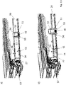
- the drawing shows a vehicle roof 10 which is a panoramic roof of a passenger car and has a front or bow-side transparent roof section 11 and a rear or rear-side transparent roof section 12 .
- the front transparent roof section 11 is formed by an adjustable cover element of a sliding roof system.
- the transparent roof sections 11 and 12 are framed by an opaque fixed roof section 13 and separated from one another by a fixed roof section 14 that is also opaque and extends in the transverse direction of the vehicle.
- the vehicle roof 10 has a roller blind arrangement 15, which comprises two roller blind units 16 and 17, of which the roller blind unit 16 is used for shading of the front transparent roof section 11 and the roller blind unit 17 for shading the rear transparent roof section 12 is used.
- the roller blind unit 16 has a roller blind web 18
- the roller blind unit 17 has a roller blind web 19 .
- the two roller blind webs 18 and 19 are each formed from an opaque, windable material and can be wound up in the area below the fixed roof section 14 extending in the transverse direction of the roof to form a roller blind roll 20 or 21 .
- the roller blind 18 and 19 each have a pull bow 22 or 23, which is arranged on the respective roller blind 18 or 19 on an edge facing away from the roller blind 20 or 21 .
- roller blind units 16 and 17 are of the same design in the present case, which is why the following description is essentially only based on the roller blind unit 16 assigned to the front transparent roof section 11 .
- the roller blind assembly 15 includes a bearing shell 24, which is connected from below to a roof frame 27, which is a roof-mounted support section and a pair of front guide rails or guide rail profiles 25A and 25B, which are arranged along lateral edges of the front transparent roof section 11, and a pair rear guide rails or guide rail profiles 26A and 26B, respectively, which are arranged along lateral edges of the rear transparent roof section 12.
- the bearing shell 24 forms a support plate or a roller blind pan for the roller blind units 16 and 17 and extends below the fixed roof section 14 in the transverse direction of the roof.
- the bearing shell 24 is provided with a fixing plate 28A or 28B at its edges, which are arranged on both sides in relation to the vertical longitudinal center plane of the roof, which can be screwed to a respective B-pillar of the relevant vehicle body. Furthermore, the bearing shell 24 forms run-off edges for the roller blind webs 18 and 19 on its edges running in the transverse direction of the roof.
- the roller blind units 16 and 17 each comprise bearing units 30 which are mirror-symmetrical to one another in relation to the vertical longitudinal center plane of the roof, via which the respective roller blind unit 16 or 17 is mounted on the one hand on the bearing shell 24 and on the other hand is connected to the respective guide rails 25A and 25B or 26A and 26B .
- the roller blind units 16 and 17 are not specified in each case shown winding shaft, which is rotatably mounted between the respective bearing units 30 and has a winding tube pretensioned by means of a winding spring, not shown in detail, in the winding direction of the respective roller blind web 18 or 19 .
- the bearing units 30 each have a bearing journal 32 which is formed on the inside of the respective bearing unit 30 facing the respective roller blind roll 20 or 21 .
- the storage units 30, one of which in the Figures 6 to 8 is shown on its own are each formed in two parts and include a bearing block 301 and a roller blind guide element 302.
- the bearing block 301 is fastened to the upper side of the bearing shell 24 by means of a fixing screw 303 which engages from below.
- the roller blind guide element 302 is inserted from the front into the bearing block 301 in the manner of a drawer in relation to the pull-out direction of the respective roller blind and is secured in a pre-assembly position by means of latching lugs 304 and 305 on the respective bearing block 301 .
- the bearing block 301 has a pin 306 on its underside, which engages in a slot 241 in the bearing shell 24 .
- the roller blind guide element 302 which is movably mounted in the respective bearing block 301 both in the vertical and transverse direction of the roof and in the longitudinal direction of the roof, has a guide section 307, which is pushed into the bearing block 301, and a front centering section 308, by means of which the roller blind guide element 302 is exactly opposite the roof frame 27 or the respective guide rail 25A, 25B, 26A or 26B can be positioned.
- the centering section 308 has at its top a positioning projection representing a centering rib 309 which, like the Figures 16a and 16b can be seen, engages from below in a channel 34 of the respective guide rail, which forms a receptacle of the support section. To make it easier for the centering rib 309 to dip into the channel 34, it has a flank on both sides that is designed as an insertion bevel 310.
- the centering rib 309 enables an exact positioning of the roller blind guide element 302 in relation to the respective guide rail 25A, 25B, 26A or 26B in the transverse direction of the roof.
- the guide section 307 has an end face 311 which, in the assembly position, rests flush against an end face of the relevant guide rail 25A, 25B, 26A or 26B.
- centering pins 312 are also formed in the area of the end face 311, which engage in channels of the respective guide rail profile 25A, 25B, 26A or 26B, which each form a centering recess fixed to the roof .
- a guide track 313 is formed on the guide section 307 of the blind guide element 302, which is aligned with a channel 35 of the respective guide rail 25A, 25B, 26A or 26B and in which a respective lateral guide band of the respective blind track 18 or 19 is guided.
- the guide track 313 is delimited at the top by a web 314, on the top of which a groove 315 is formed, which is interrupted by a latching lug 316, by means of which a pull bow slider 33 can be secured in a pre-assembled state on the roller blind guide element 302 of the respective storage unit 30.
- the roller blind guide elements 302 of the bearing units 30 also have a fixing bracket 317 on their front end facing away from the respective bearing block 301, which is provided with a screw hole 318, which is arranged on the side in the extension direction of the respective roller blind web 18 or 19, i.e on the end face of the respective roller blind guide element 302 is open and via which the respective roller blind guide element 302 is screwed to a respective guide rail 25A, 25B, 26A or 26B by means of a fixing screw 36 (cf. figure 17 ).
- roller blind guide elements 302 each have a recessed grip 319 on their underside.
- the roller blind guide elements 302 protrude beyond an edge of the bearing shell 24 in the extension direction of the relevant roller blind web 18 or 19, so that the recessed grip 319 can be gripped by a worker from below so that he can position the roller blind guide elements 302 in relation to the bearing blocks 301 can move in the direction of the fixing screws 36 that the screw holes 318 surround the fixing screws 36 like a fork and the end faces 311 at the strike corresponding end faces of the relevant guide rails 25A, 25B, 26A and 26B.
- the centering pins 312 then engage in corresponding channels in the guide rails.
- roller blind units 16 and 17 are each driven by a drive motor of a drive motor unit 68, which is arranged below a rear area of the opaque fixed roof section 13 and drives the drive cables 39, which are each coupled to a respective pull bow slider 33 via a coupling element 70.
- the coupling elements 70 of the drive cables 39 are hook-shaped in cross section, so that they each have a tongue 71 which is aligned parallel to the vertical longitudinal center plane of the roof and engages in a receptacle 72 which is formed in the respective pull bow slider 33.
- the tongue 71 dips into the receptacle 72 of the pull-up bow slider 33 from above when the modular roller blind arrangement 15 is moved up to the roof frame 27 .
- the tongue 71 has flanks 73 which are designed as chamfers and which interact with the chamfers 74 and 75 of the receptacle 72 of the pull bow slider 33, so that the tongue 70 is guided into it in a precisely positioned manner and without play.
- the bearing shell 24 of the blind assembly 15 is provided in the area between the two blind units 16 and 17 with two mounting clips 50, like the Figures 10 to 13 can be seen, are each locked in a rectangular recess 51 of the bearing shell 24 and has a substantially rectangular cross section.
- the mounting clips 50 each have first locking tabs 52 on the underside, which engage behind the bearing shell 24 .
- stops 53 are formed which protrude in the transverse direction and bear against the upper side of the bearing shell 24 .
- the mounting clips 50 have second latching lugs 53 on their flanks on both sides, which are offset by 90° with respect to the first latching lugs 52 and via which the mounting clips 50 can be held in a pre-assembly position (cf. figure 13b ) can be latched to the roof frame 27 from below.
- the mounting clips 50 which each have four locking tabs, each reach through a mounting recess 54 of the roof frame 27. In this pre-assembly position, fixing screws 55 engage with their free end faces in threads 56, which are formed on the roof frame 27 for fixing the roller blind arrangement 15.
- centering pins 57 pointing in the vertical direction of the roof are arranged on the upper side of the bearing shell 24 Figure 13b engage shown pre-assembly position and in their final position in corresponding centering recesses of the roof frame 27.
- the pull-out bow sliders 33 each have a connecting strap 60 for the guide strip of the relevant roller blind 18 or 19 and a slide rail 61 on their lower lateral edges, which enables the pull-out bow sliders 33 can run over the interface between the respective guide rail 25A, 25B, 26A or 26B and the respective roller blind guide element 302 in a noise-optimized manner during regular operation of the blind arrangement 15 when the respective blind web 18 or 19 is opened or wound up. This ensures that a maximum area of the respective roof section 11 or 12 can be released for viewing.
- the pull bow sliders 33 each have a spring element 62, which holds them with tension in the respective guide rail 25A, 25B, 26A or 26B.
- roller blind arrangement 15 described above is assembled in the manner described below.
- the roller blind arrangement 15 is assembled, ie the bearing shell 24 is provided with the roller blind units 16 and 17 , with the bearing blocks 301 of the bearing units 30 being screwed to the bearing shell 24 via the fixing screws 303 .
- the fixing plates 28A and 28B are attached.
- the mounting clips 50 are inserted into the recesses 51 and the centering pins 57 are screwed on by means of screws engaging from below.
- the blind arrangement 15 provided in this way is then moved up from below to the fixed roof section 14 extending in the transverse direction of the roof, with the mounting clips 50 in the Mounting recesses 54 of the roof frame 27 are locked and immerse the centering pins in corresponding centering recesses of the roof frame 27.
- the roller blind guide elements 302 are moved in the longitudinal direction of the guide rails relative to the bearing blocks 301 and relative to the bearing shell 24 until the end faces 311 strike the front sides of the guide rails and the screw holes 318 grip the fixing screws 36, for example by manually gripping the roller blind guide elements 302 in the area the recessed grips 319 or by engaging an assembly mandrel in a hole 320 on the underside of the respective roller blind guide element 302. The screws 36 are then tightened.
- roller blind guide elements 302 This results in an exact positioning of the roller blind guide elements 302 in relation to the roof frame 27 .
- the roller blind arrangement 15 can now be put into operation.
Landscapes
- Engineering & Computer Science (AREA)
- Mechanical Engineering (AREA)
- Structural Engineering (AREA)
- Architecture (AREA)
- Civil Engineering (AREA)
- Chemical & Material Sciences (AREA)
- Combustion & Propulsion (AREA)
- Transportation (AREA)
- Operating, Guiding And Securing Of Roll- Type Closing Members (AREA)
Claims (15)
- Toit de véhicule, comprenant au moins une partie de toit transparente (11, 12), une partie de support fixé sur le toit et un ensemble de store (15) pour ombrer au choix ou dégager la partie de toit transparente (11, 12) au moins en partie, ledit ensemble de store (15) présentant au moins une unité de store (16, 17) qui comprend un store (18, 19), qui peut être enroulé pour former un rouleau de store (20, 21), et une unité de palier (30) latérale de chaque côté d'un plan médian longitudinal vertical du toit, ledit rouleau de store (20, 21) étant disposé entre les deux unités de palier (30) latérales et ledit ensemble de store (15) comprenant une coque de palier (24) au-dessus de laquelle l'au moins une unité de store (16, 17) est fixée par les unités de palier (30) latérales et qui est fixée sur l'au moins une partie de support d'en bas, caractérisé en ce que chacune des unités de palier (30) comprend une chaise de palier (301) qui est fixée sur la coque de palier (24) et un élément de guidage de store (302) qui peut être déplacé par rapport à la chaise de palier (301) dans une position de prémontage et est fixé sur la partie de support fixé sur le toit dans une position de montage.
- Toit de véhicule selon la revendication 1, caractérisé en ce que chacun des éléments de guidage de store (302) saillit au-delà d'un bord de la coque de palier (24) dans la direction dans laquelle le store (18, 19) est déplié.
- Toit de véhicule selon la revendication 1 ou 2, caractérisé en ce que chacun des éléments de guidage de store (302) présente un trou de vis (318) qui est ouvert d'un côté disposé dans la direction dans laquelle le store (18, 19) est déplié et par lequel l'élément de guidage de store (302) respectif est vissé à la partie de support fixé sur le toit.
- Toit de véhicule selon l'une quelconque des revendications 1 à 3, caractérisé en ce que chacun des éléments de guidage de store (302) présente une poignée encastrée (319) sur sa face inférieure.
- Toit de véhicule selon l'une quelconque des revendications 1 à 4, caractérisé en ce que chacun des éléments de guidage de store (302) présente une voie de centrage (313) dans laquelle une bande de guidage latérale du store (18, 19) est guidée et qui est alignée avec un canal d'un profilé d'un rail de guidage (25A, 25B, 26A, 26B) qui fait partie de la partie de support.
- Toit de véhicule selon l'une quelconque des revendications 1 à 5, caractérisé en ce que chacun des éléments de guidage de store (302) a une voie de guidage (34) pour une glissière d'arceau tracteur (33), chaque voie de guidage (34) étant alignée avec un canal de guidage (35) d'un profilé d'un rail de guidage (25A, 25B, 26A, 26B) qui fait partie de la partie de support, chacun des éléments de guidage de store (302) présentant de préférence une éclisse de verrouillage (316) qui retient la glissière d'arceau tracteur (33) respective sur l'élément de guidage de store (302) respectif dans un état de prémontage.
- Toit de véhicule selon l'une quelconque des revendications 1 à 6, caractérisé en ce que chacun des éléments de guidage de store (302) est monté dans la chaise de palier (301) respective avec jeu dans au moins deux directions spatiales.
- Toit de véhicule selon l'une quelconque des revendications 1 à 7, caractérisé en ce que les éléments de guidage de store (302), dans un état de prémontage, sont fixés dans la chaise de palier (301) respective moyennant un moyen de verrouillage (304, 305).
- Toit de véhicule selon l'une quelconque des revendications 1 à 8, caractérisé en ce que chacun des éléments de guidage de store (302) présente un épaulement de positionnement qui s'engage dans un logement correspondant de la partie de support d'en bas et qui est notamment réalisé comme renfort de centrage (309) qui s'étend dans la direction dans laquelle le store (18, 19) est déplié.
- Toit de véhicule selon l'une quelconque des revendications 1 à 9, caractérisé en ce que chacun des éléments de guidage de store (302) comprend au moins un tenon de centrage (312) disposé sur la face frontale et s'engageant dans une cavité de centrage fixée sur le toit, la cavité de centrage étant formée de préférence par un profilé d'un rail de guidage (25A, 25B, 26A, 26B) avec lequel une face frontale (311) de l'élément de guidage de store (302) respectif est en contact dans une position de montage.
- Toit de véhicule selon l'une quelconque des revendications 1 à 10, caractérisé en ce que des glissières d'arceau tracteur (33) sont prévues dont chacune présente un logement (72) pour un élément de couplage (70) d'un câble d'entraînement (39) respectif qui est entrainé par un moteur d'entraînement, ledit logement (72) de préférence étant ouvert vers le haut et logeant l'élément de couplage (70) sans jeu dans la direction longitudinale du profilé d'un rail de guidage (25A, 25B, 26A, 26B) respectif, chacun des logements (72) ayant de préférence des pentes d'entrée (74, 75) pour l'élément de couplage (70) respectif, et chacun des éléments de couplage (70) des câbles d'entraînement (39) ayant de préférence une section transversale unciforme et comprenant une langue (71) qui est orientée en parallèle par rapport au plan médian longitudinal vertical du toit.
- Toit de véhicule selon l'une quelconque des revendications 1 à 11, caractérisé en ce que chacune des chaises de palier (301) comprend un tenon de palier (32) pour un tube d'enroulement.
- Toit de véhicule selon l'une quelconque des revendications 1 à 12, caractérisé en ce que la coque de palier (24) est pourvue d'au moins une attache de montage (50) qui retient ladite coque de palier (24) sur la partie de support dans une position de prémontage et qui a de préférence une section transversale rectangulaire, ladite attache de montage (50) étant verrouillée de préférence dans une cavité (51) de la coque de palier (24), et ladite attache de montage (50), dans la position de prémontage, de préférence étant verrouillée dans une cavité de montage (54) de la partie de support d'en bas avec jeu dans la direction verticale du toit.
- Toit de véhicule selon l'une quelconque des revendications 1 à 13, caractérisé en ce que la partie de support est formée par un cadre d'un système d'ouverture d'un toit.
- Toit de véhicule selon l'une quelconque des revendications 1 à 14, caractérisé en ce que l'ensemble de store (15) comprend deux unités de store (16, 17) qui sont disposées sur la coque de palier (24).
Applications Claiming Priority (2)
| Application Number | Priority Date | Filing Date | Title |
|---|---|---|---|
| DE102018108354.8A DE102018108354B4 (de) | 2018-04-09 | 2018-04-09 | Fahrzeugdach, umfassend eine Rolloanordnung mit Lagereinheiten für Rollobahn |
| PCT/EP2019/053959 WO2019197071A1 (fr) | 2018-04-09 | 2019-02-18 | Toit de véhicule, comprenant un agencement de store pourvu d'unités de paliers pour bande de store |
Publications (2)
| Publication Number | Publication Date |
|---|---|
| EP3774419A1 EP3774419A1 (fr) | 2021-02-17 |
| EP3774419B1 true EP3774419B1 (fr) | 2022-07-13 |
Family
ID=65685292
Family Applications (1)
| Application Number | Title | Priority Date | Filing Date |
|---|---|---|---|
| EP19708956.8A Active EP3774419B1 (fr) | 2018-04-09 | 2019-02-18 | Toit de véhicule comprenant un ensemble de volets roulants avec des unités de support de roulement à rouleaux. |
Country Status (5)
| Country | Link |
|---|---|
| US (1) | US10974579B2 (fr) |
| EP (1) | EP3774419B1 (fr) |
| CN (1) | CN112041183B (fr) |
| DE (1) | DE102018108354B4 (fr) |
| WO (1) | WO2019197071A1 (fr) |
Families Citing this family (4)
| Publication number | Priority date | Publication date | Assignee | Title |
|---|---|---|---|---|
| DE102018205683B4 (de) * | 2018-04-13 | 2024-02-29 | Bayerische Motoren Werke Aktiengesellschaft | Dachsystem für ein fahrzeug, fahrzeug mit einem solchen dachsystem, dachelement und herstellungsverfahren |
| US11904670B2 (en) | 2021-02-04 | 2024-02-20 | Mytop Ip, Llc | Sliding soft-top convertible roof |
| DE102021206022A1 (de) * | 2021-06-14 | 2022-12-15 | Bos Gmbh & Co. Kg | Beschattungsvorrichtung für einen Fahrzeuginnenraum eines Kraftfahrzeugs |
| GB2612810B (en) * | 2021-11-12 | 2024-03-20 | Jaguar Land Rover Ltd | Blind mounting apparatus and method |
Family Cites Families (14)
| Publication number | Priority date | Publication date | Assignee | Title |
|---|---|---|---|---|
| DE3607725A1 (de) | 1986-03-08 | 1987-09-17 | Webasto Werk Baier Kg W | Fahrzeugdach |
| JPH0428814Y2 (fr) * | 1986-04-22 | 1992-07-14 | ||
| JP2518113B2 (ja) * | 1991-05-28 | 1996-07-24 | 豊田合成株式会社 | クリップ付成形品の製造方法 |
| DE102004020337B4 (de) * | 2004-01-13 | 2007-06-21 | Webasto Ag | Fahrzeugdach mit einer Rolloanordnung |
| JP5219075B2 (ja) | 2008-08-29 | 2013-06-26 | トヨタ車体株式会社 | 自動車のルーフ構造 |
| DE102011007004B8 (de) * | 2011-04-07 | 2013-01-10 | Bos Gmbh & Co. Kg | Rollobaueinheit für ein Kraftfahrzeug |
| DE102011113207B4 (de) | 2011-09-08 | 2014-07-03 | Webasto Ag | Fahrzeugrolloanordnung und Fahrzeugdach |
| KR101233770B1 (ko) | 2012-06-21 | 2013-02-15 | (주)베바스토동희 홀딩스 | 파노라마 선루프용 롤러 블라인드 장치 |
| DE102014005476A1 (de) | 2014-04-15 | 2015-10-15 | Webasto SE | Rollovorrichtung an einem Fahrzeugdach |
| EP3100883B1 (fr) * | 2015-06-01 | 2018-02-28 | Inalfa Roof Systems Group B.V. | Mécanisme d'enroulement et construction de toit ouvrant pour véhicule comprenant celui-ci |
| DE102015109862A1 (de) * | 2015-06-19 | 2016-12-22 | Webasto SE | Fahrzeugdach mit Rolloanordnung |
| JP6517646B2 (ja) * | 2015-09-24 | 2019-05-22 | アイシン精機株式会社 | シェード装置 |
| DE102016111695A1 (de) | 2016-06-27 | 2017-12-28 | Webasto SE | Rolloanordnung für eine Fahrzeugkarosserie und Verfahren zum Zusammenbau der Rolloanordnung |
| DE102016125284B4 (de) * | 2016-12-21 | 2018-07-05 | Webasto SE | Fahrzeugdach mit Trägerabschnitt und Rolloanordnung |
-
2018
- 2018-04-09 DE DE102018108354.8A patent/DE102018108354B4/de active Active
-
2019
- 2019-02-18 WO PCT/EP2019/053959 patent/WO2019197071A1/fr unknown
- 2019-02-18 CN CN201980024376.7A patent/CN112041183B/zh active Active
- 2019-02-18 EP EP19708956.8A patent/EP3774419B1/fr active Active
- 2019-02-18 US US16/981,829 patent/US10974579B2/en active Active
Also Published As
| Publication number | Publication date |
|---|---|
| EP3774419A1 (fr) | 2021-02-17 |
| CN112041183A (zh) | 2020-12-04 |
| CN112041183B (zh) | 2022-06-07 |
| DE102018108354A1 (de) | 2019-10-10 |
| US20210046810A1 (en) | 2021-02-18 |
| DE102018108354B4 (de) | 2022-02-24 |
| US10974579B2 (en) | 2021-04-13 |
| WO2019197071A1 (fr) | 2019-10-17 |
Similar Documents
| Publication | Publication Date | Title |
|---|---|---|
| EP3774419B1 (fr) | Toit de véhicule comprenant un ensemble de volets roulants avec des unités de support de roulement à rouleaux. | |
| EP3558732B1 (fr) | Toit de véhicule avec section de support et arrangement de rollo | |
| WO2016202505A1 (fr) | Toit de véhicule muni d'un système de store | |
| DE102008036839B4 (de) | Scheibenglasbefestigung für bewegliches Fahrzeugfenster | |
| DE102011018151A1 (de) | Baugruppe für ein öffnungsfähiges Schiebedach | |
| DE102005056662B4 (de) | Einrichtung zum Befestigen eines Dachgepäckträgers | |
| EP3427984A1 (fr) | Dispositif de protection d'habitacle de véhicule | |
| WO2013120699A1 (fr) | Système d'ombrage d'un véhicule composé de deux unités d'ombrage et procédé de montage d'un système d'ombrage | |
| EP2935739B1 (fr) | Dispositif de recouvrement pour un module flasque de retenue pouvant être amené en accouplement libérable a l'aide d'un module a clavettes de fermeture créant une liaison entre une porte de véhicule et un cadre de paroi latérale sur une carrosserie de véhicule | |
| EP3142878B1 (fr) | Ensemble store avec guidage latéral | |
| DE102015109274B3 (de) | Rolloanordnung mit Triebmittel zur Seitenführung einer Rollobahn | |
| DE3522047C2 (fr) | ||
| DE102008017074B3 (de) | Deckelelementträger | |
| EP1348585B1 (fr) | Panneau déplaçable pour toit de véhicule et module pour toit coulissant | |
| EP1071572B1 (fr) | Dispositif d'ajustage pour toit a ailerons multiples de vehicule | |
| DE102007002857B4 (de) | Rolloanordnung mit Führungselement | |
| DE10048981A1 (de) | Öffnungsfähiges Fahrzeugdach | |
| DE102021114037B4 (de) | Festdachelement mit Führungsschiene und Gleiter | |
| DE102011055196B4 (de) | Abdeckeinrichtung | |
| DE102021124555B4 (de) | Rolloanordnung mit Zugspriegel und Antriebskabeln | |
| DE102018116227B4 (de) | Mehrteiliger Rahmen für ein Fahrzeug-Schiebedach oder Fahrzeug-Schiebehebedach und Verfahren zur Montage eines mehrteiligen Rahmens | |
| DE202007008049U1 (de) | Führungsbaugruppe eines Kraftfahrzeugfensterhebers | |
| DE102006061505A1 (de) | Rolloeinheit sowie korrespondierende Tragvorrichtung | |
| DE102023002359A1 (de) | Fahrzeug | |
| DE102021206022A1 (de) | Beschattungsvorrichtung für einen Fahrzeuginnenraum eines Kraftfahrzeugs |
Legal Events
| Date | Code | Title | Description |
|---|---|---|---|
| STAA | Information on the status of an ep patent application or granted ep patent |
Free format text: STATUS: UNKNOWN |
|
| STAA | Information on the status of an ep patent application or granted ep patent |
Free format text: STATUS: THE INTERNATIONAL PUBLICATION HAS BEEN MADE |
|
| PUAI | Public reference made under article 153(3) epc to a published international application that has entered the european phase |
Free format text: ORIGINAL CODE: 0009012 |
|
| STAA | Information on the status of an ep patent application or granted ep patent |
Free format text: STATUS: REQUEST FOR EXAMINATION WAS MADE |
|
| 17P | Request for examination filed |
Effective date: 20200916 |
|
| AK | Designated contracting states |
Kind code of ref document: A1 Designated state(s): AL AT BE BG CH CY CZ DE DK EE ES FI FR GB GR HR HU IE IS IT LI LT LU LV MC MK MT NL NO PL PT RO RS SE SI SK SM TR |
|
| AX | Request for extension of the european patent |
Extension state: BA ME |
|
| DAV | Request for validation of the european patent (deleted) | ||
| DAX | Request for extension of the european patent (deleted) | ||
| GRAP | Despatch of communication of intention to grant a patent |
Free format text: ORIGINAL CODE: EPIDOSNIGR1 |
|
| STAA | Information on the status of an ep patent application or granted ep patent |
Free format text: STATUS: GRANT OF PATENT IS INTENDED |
|
| INTG | Intention to grant announced |
Effective date: 20211116 |
|
| GRAJ | Information related to disapproval of communication of intention to grant by the applicant or resumption of examination proceedings by the epo deleted |
Free format text: ORIGINAL CODE: EPIDOSDIGR1 |
|
| STAA | Information on the status of an ep patent application or granted ep patent |
Free format text: STATUS: REQUEST FOR EXAMINATION WAS MADE |
|
| RBV | Designated contracting states (corrected) |
Designated state(s): AL AT BE BG CH CY CZ DK EE ES FI FR GB GR HR HU IE IS IT LI LT LU LV MC MK MT NL NO PL PT RO RS SE SI SK SM TR |
|
| REG | Reference to a national code |
Ref country code: DE Ref legal event code: R108 |
|
| INTC | Intention to grant announced (deleted) | ||
| GRAP | Despatch of communication of intention to grant a patent |
Free format text: ORIGINAL CODE: EPIDOSNIGR1 |
|
| STAA | Information on the status of an ep patent application or granted ep patent |
Free format text: STATUS: GRANT OF PATENT IS INTENDED |
|
| GRAS | Grant fee paid |
Free format text: ORIGINAL CODE: EPIDOSNIGR3 |
|
| GRAA | (expected) grant |
Free format text: ORIGINAL CODE: 0009210 |
|
| STAA | Information on the status of an ep patent application or granted ep patent |
Free format text: STATUS: THE PATENT HAS BEEN GRANTED |
|
| INTG | Intention to grant announced |
Effective date: 20220531 |
|
| AK | Designated contracting states |
Kind code of ref document: B1 Designated state(s): AL AT BE BG CH CY CZ DK EE ES FI FR GB GR HR HU IE IS IT LI LT LU LV MC MK MT NL NO PL PT RO RS SE SI SK SM TR |
|
| REG | Reference to a national code |
Ref country code: CH Ref legal event code: EP |
|
| REG | Reference to a national code |
Ref country code: AT Ref legal event code: REF Ref document number: 1504103 Country of ref document: AT Kind code of ref document: T Effective date: 20220815 |
|
| REG | Reference to a national code |
Ref country code: IE Ref legal event code: FG4D Free format text: LANGUAGE OF EP DOCUMENT: GERMAN |
|
| REG | Reference to a national code |
Ref country code: LT Ref legal event code: MG9D |
|
| PG25 | Lapsed in a contracting state [announced via postgrant information from national office to epo] |
Ref country code: SE Free format text: LAPSE BECAUSE OF FAILURE TO SUBMIT A TRANSLATION OF THE DESCRIPTION OR TO PAY THE FEE WITHIN THE PRESCRIBED TIME-LIMIT Effective date: 20220713 Ref country code: RS Free format text: LAPSE BECAUSE OF FAILURE TO SUBMIT A TRANSLATION OF THE DESCRIPTION OR TO PAY THE FEE WITHIN THE PRESCRIBED TIME-LIMIT Effective date: 20220713 Ref country code: PT Free format text: LAPSE BECAUSE OF FAILURE TO SUBMIT A TRANSLATION OF THE DESCRIPTION OR TO PAY THE FEE WITHIN THE PRESCRIBED TIME-LIMIT Effective date: 20221114 Ref country code: NO Free format text: LAPSE BECAUSE OF FAILURE TO SUBMIT A TRANSLATION OF THE DESCRIPTION OR TO PAY THE FEE WITHIN THE PRESCRIBED TIME-LIMIT Effective date: 20221013 Ref country code: NL Free format text: LAPSE BECAUSE OF FAILURE TO SUBMIT A TRANSLATION OF THE DESCRIPTION OR TO PAY THE FEE WITHIN THE PRESCRIBED TIME-LIMIT Effective date: 20220713 Ref country code: LV Free format text: LAPSE BECAUSE OF FAILURE TO SUBMIT A TRANSLATION OF THE DESCRIPTION OR TO PAY THE FEE WITHIN THE PRESCRIBED TIME-LIMIT Effective date: 20220713 Ref country code: LT Free format text: LAPSE BECAUSE OF FAILURE TO SUBMIT A TRANSLATION OF THE DESCRIPTION OR TO PAY THE FEE WITHIN THE PRESCRIBED TIME-LIMIT Effective date: 20220713 Ref country code: FI Free format text: LAPSE BECAUSE OF FAILURE TO SUBMIT A TRANSLATION OF THE DESCRIPTION OR TO PAY THE FEE WITHIN THE PRESCRIBED TIME-LIMIT Effective date: 20220713 Ref country code: ES Free format text: LAPSE BECAUSE OF FAILURE TO SUBMIT A TRANSLATION OF THE DESCRIPTION OR TO PAY THE FEE WITHIN THE PRESCRIBED TIME-LIMIT Effective date: 20220713 |
|
| PG25 | Lapsed in a contracting state [announced via postgrant information from national office to epo] |
Ref country code: PL Free format text: LAPSE BECAUSE OF FAILURE TO SUBMIT A TRANSLATION OF THE DESCRIPTION OR TO PAY THE FEE WITHIN THE PRESCRIBED TIME-LIMIT Effective date: 20220713 Ref country code: IS Free format text: LAPSE BECAUSE OF FAILURE TO SUBMIT A TRANSLATION OF THE DESCRIPTION OR TO PAY THE FEE WITHIN THE PRESCRIBED TIME-LIMIT Effective date: 20221113 Ref country code: HR Free format text: LAPSE BECAUSE OF FAILURE TO SUBMIT A TRANSLATION OF THE DESCRIPTION OR TO PAY THE FEE WITHIN THE PRESCRIBED TIME-LIMIT Effective date: 20220713 Ref country code: GR Free format text: LAPSE BECAUSE OF FAILURE TO SUBMIT A TRANSLATION OF THE DESCRIPTION OR TO PAY THE FEE WITHIN THE PRESCRIBED TIME-LIMIT Effective date: 20221014 |
|
| PG25 | Lapsed in a contracting state [announced via postgrant information from national office to epo] |
Ref country code: SM Free format text: LAPSE BECAUSE OF FAILURE TO SUBMIT A TRANSLATION OF THE DESCRIPTION OR TO PAY THE FEE WITHIN THE PRESCRIBED TIME-LIMIT Effective date: 20220713 Ref country code: RO Free format text: LAPSE BECAUSE OF FAILURE TO SUBMIT A TRANSLATION OF THE DESCRIPTION OR TO PAY THE FEE WITHIN THE PRESCRIBED TIME-LIMIT Effective date: 20220713 Ref country code: DK Free format text: LAPSE BECAUSE OF FAILURE TO SUBMIT A TRANSLATION OF THE DESCRIPTION OR TO PAY THE FEE WITHIN THE PRESCRIBED TIME-LIMIT Effective date: 20220713 Ref country code: CZ Free format text: LAPSE BECAUSE OF FAILURE TO SUBMIT A TRANSLATION OF THE DESCRIPTION OR TO PAY THE FEE WITHIN THE PRESCRIBED TIME-LIMIT Effective date: 20220713 |
|
| PLBE | No opposition filed within time limit |
Free format text: ORIGINAL CODE: 0009261 |
|
| STAA | Information on the status of an ep patent application or granted ep patent |
Free format text: STATUS: NO OPPOSITION FILED WITHIN TIME LIMIT |
|
| PG25 | Lapsed in a contracting state [announced via postgrant information from national office to epo] |
Ref country code: SK Free format text: LAPSE BECAUSE OF FAILURE TO SUBMIT A TRANSLATION OF THE DESCRIPTION OR TO PAY THE FEE WITHIN THE PRESCRIBED TIME-LIMIT Effective date: 20220713 Ref country code: EE Free format text: LAPSE BECAUSE OF FAILURE TO SUBMIT A TRANSLATION OF THE DESCRIPTION OR TO PAY THE FEE WITHIN THE PRESCRIBED TIME-LIMIT Effective date: 20220713 |
|
| 26N | No opposition filed |
Effective date: 20230414 |
|
| PG25 | Lapsed in a contracting state [announced via postgrant information from national office to epo] |
Ref country code: AL Free format text: LAPSE BECAUSE OF FAILURE TO SUBMIT A TRANSLATION OF THE DESCRIPTION OR TO PAY THE FEE WITHIN THE PRESCRIBED TIME-LIMIT Effective date: 20220713 |
|
| PG25 | Lapsed in a contracting state [announced via postgrant information from national office to epo] |
Ref country code: SI Free format text: LAPSE BECAUSE OF FAILURE TO SUBMIT A TRANSLATION OF THE DESCRIPTION OR TO PAY THE FEE WITHIN THE PRESCRIBED TIME-LIMIT Effective date: 20220713 |
|
| PG25 | Lapsed in a contracting state [announced via postgrant information from national office to epo] |
Ref country code: MC Free format text: LAPSE BECAUSE OF FAILURE TO SUBMIT A TRANSLATION OF THE DESCRIPTION OR TO PAY THE FEE WITHIN THE PRESCRIBED TIME-LIMIT Effective date: 20220713 |
|
| REG | Reference to a national code |
Ref country code: CH Ref legal event code: PL |
|
| REG | Reference to a national code |
Ref country code: BE Ref legal event code: MM Effective date: 20230228 |
|
| GBPC | Gb: european patent ceased through non-payment of renewal fee |
Effective date: 20230218 |
|
| PG25 | Lapsed in a contracting state [announced via postgrant information from national office to epo] |
Ref country code: LU Free format text: LAPSE BECAUSE OF NON-PAYMENT OF DUE FEES Effective date: 20230218 Ref country code: LI Free format text: LAPSE BECAUSE OF NON-PAYMENT OF DUE FEES Effective date: 20230228 Ref country code: CH Free format text: LAPSE BECAUSE OF NON-PAYMENT OF DUE FEES Effective date: 20230228 |
|
| REG | Reference to a national code |
Ref country code: IE Ref legal event code: MM4A |
|
| PG25 | Lapsed in a contracting state [announced via postgrant information from national office to epo] |
Ref country code: GB Free format text: LAPSE BECAUSE OF NON-PAYMENT OF DUE FEES Effective date: 20230218 |
|
| PG25 | Lapsed in a contracting state [announced via postgrant information from national office to epo] |
Ref country code: IT Free format text: LAPSE BECAUSE OF FAILURE TO SUBMIT A TRANSLATION OF THE DESCRIPTION OR TO PAY THE FEE WITHIN THE PRESCRIBED TIME-LIMIT Effective date: 20220713 Ref country code: IE Free format text: LAPSE BECAUSE OF NON-PAYMENT OF DUE FEES Effective date: 20230218 Ref country code: GB Free format text: LAPSE BECAUSE OF NON-PAYMENT OF DUE FEES Effective date: 20230218 |
|
| PG25 | Lapsed in a contracting state [announced via postgrant information from national office to epo] |
Ref country code: BE Free format text: LAPSE BECAUSE OF NON-PAYMENT OF DUE FEES Effective date: 20230228 |
|
| PGFP | Annual fee paid to national office [announced via postgrant information from national office to epo] |
Ref country code: FR Payment date: 20240221 Year of fee payment: 6 |