EP3774342B1 - Flexodruckvorrichtung und verfahren zum gleichzeitigen bedrucken von mindestens zwei materialbahnen mit unterschiedlichen dicken - Google Patents
Flexodruckvorrichtung und verfahren zum gleichzeitigen bedrucken von mindestens zwei materialbahnen mit unterschiedlichen dicken Download PDFInfo
- Publication number
- EP3774342B1 EP3774342B1 EP18913317.6A EP18913317A EP3774342B1 EP 3774342 B1 EP3774342 B1 EP 3774342B1 EP 18913317 A EP18913317 A EP 18913317A EP 3774342 B1 EP3774342 B1 EP 3774342B1
- Authority
- EP
- European Patent Office
- Prior art keywords
- printing
- printed
- roller
- webs
- material web
- Prior art date
- Legal status (The legal status is an assumption and is not a legal conclusion. Google has not performed a legal analysis and makes no representation as to the accuracy of the status listed.)
- Active
Links
Images



Classifications
-
- A—HUMAN NECESSITIES
- A61—MEDICAL OR VETERINARY SCIENCE; HYGIENE
- A61F—FILTERS IMPLANTABLE INTO BLOOD VESSELS; PROSTHESES; DEVICES PROVIDING PATENCY TO, OR PREVENTING COLLAPSING OF, TUBULAR STRUCTURES OF THE BODY, e.g. STENTS; ORTHOPAEDIC, NURSING OR CONTRACEPTIVE DEVICES; FOMENTATION; TREATMENT OR PROTECTION OF EYES OR EARS; BANDAGES, DRESSINGS OR ABSORBENT PADS; FIRST-AID KITS
- A61F13/00—Bandages or dressings; Absorbent pads
- A61F13/15—Absorbent pads, e.g. sanitary towels, swabs or tampons for external or internal application to the body; Supporting or fastening means therefor; Tampon applicators
- A61F13/84—Accessories, not otherwise provided for, for absorbent pads
-
- B—PERFORMING OPERATIONS; TRANSPORTING
- B41—PRINTING; LINING MACHINES; TYPEWRITERS; STAMPS
- B41F—PRINTING MACHINES OR PRESSES
- B41F13/00—Common details of rotary presses or machines
- B41F13/08—Cylinders
- B41F13/10—Forme cylinders
-
- B—PERFORMING OPERATIONS; TRANSPORTING
- B41—PRINTING; LINING MACHINES; TYPEWRITERS; STAMPS
- B41F—PRINTING MACHINES OR PRESSES
- B41F13/00—Common details of rotary presses or machines
- B41F13/08—Cylinders
- B41F13/18—Impression cylinders
-
- B—PERFORMING OPERATIONS; TRANSPORTING
- B41—PRINTING; LINING MACHINES; TYPEWRITERS; STAMPS
- B41F—PRINTING MACHINES OR PRESSES
- B41F5/00—Rotary letterpress machines
- B41F5/24—Rotary letterpress machines for flexographic printing
-
- B—PERFORMING OPERATIONS; TRANSPORTING
- B41—PRINTING; LINING MACHINES; TYPEWRITERS; STAMPS
- B41M—PRINTING, DUPLICATING, MARKING, OR COPYING PROCESSES; COLOUR PRINTING
- B41M1/00—Inking and printing with a printer's forme
- B41M1/02—Letterpress printing, e.g. book printing
- B41M1/04—Flexographic printing
-
- B—PERFORMING OPERATIONS; TRANSPORTING
- B41—PRINTING; LINING MACHINES; TYPEWRITERS; STAMPS
- B41N—PRINTING PLATES OR FOILS; MATERIALS FOR SURFACES USED IN PRINTING MACHINES FOR PRINTING, INKING, DAMPING, OR THE LIKE; PREPARING SUCH SURFACES FOR USE AND CONSERVING THEM
- B41N7/00—Shells for rollers of printing machines
- B41N7/04—Shells for rollers of printing machines for damping rollers
-
- B—PERFORMING OPERATIONS; TRANSPORTING
- B41—PRINTING; LINING MACHINES; TYPEWRITERS; STAMPS
- B41N—PRINTING PLATES OR FOILS; MATERIALS FOR SURFACES USED IN PRINTING MACHINES FOR PRINTING, INKING, DAMPING, OR THE LIKE; PREPARING SUCH SURFACES FOR USE AND CONSERVING THEM
- B41N7/00—Shells for rollers of printing machines
- B41N7/06—Shells for rollers of printing machines for inking rollers
-
- A—HUMAN NECESSITIES
- A61—MEDICAL OR VETERINARY SCIENCE; HYGIENE
- A61F—FILTERS IMPLANTABLE INTO BLOOD VESSELS; PROSTHESES; DEVICES PROVIDING PATENCY TO, OR PREVENTING COLLAPSING OF, TUBULAR STRUCTURES OF THE BODY, e.g. STENTS; ORTHOPAEDIC, NURSING OR CONTRACEPTIVE DEVICES; FOMENTATION; TREATMENT OR PROTECTION OF EYES OR EARS; BANDAGES, DRESSINGS OR ABSORBENT PADS; FIRST-AID KITS
- A61F13/00—Bandages or dressings; Absorbent pads
- A61F13/15—Absorbent pads, e.g. sanitary towels, swabs or tampons for external or internal application to the body; Supporting or fastening means therefor; Tampon applicators
- A61F13/84—Accessories, not otherwise provided for, for absorbent pads
- A61F2013/8497—Accessories, not otherwise provided for, for absorbent pads having decorations or indicia means
Definitions
- the present invention relates to a flexographic printing device and a method of simultaneously printing at least two material webs having different thicknesses in the printing device as defined in the appended claims.
- Absorbent articles for absorption of body fluids are available in a number of different designs. For absorption of urine and excrement, use is generally made of diapers or incontinence guards with a shape which, during use, simulates a pair of briefs.
- absorbent articles such as feminine hygiene products. These products typically include a topsheet facing the body of the user, a backsheet facing the garment of a user, and an absorbent layer sandwiched between the inner, topsheet and outer, backsheet. To increase the aesthetics and functionality of the particular article, graphics may be printed on various portions of the article.
- the absorbent articles may comprise further structural elements adapted to improve the fit of the articles to the body of the user or to improve leakage protection.
- the absorbent articles may comprise side panels and some known hygiene articles, such as diapers which can be both open-type and pant-type, are provided with liquid side barriers along the longitudinal edges of the absorbent core which are intended to reduce the risk of side-edge leakage.
- some known hygiene articles such as diapers which can be both open-type and pant-type
- liquid side barriers along the longitudinal edges of the absorbent core which are intended to reduce the risk of side-edge leakage.
- different types printing patterns may be printed on various portions of the article.
- the topsheet and backsheet of the absorbent article may be made from a nonwoven material.
- Printing is typically applied to the particular nonwoven layer prior to attaching it to the other layers of the absorbent article.
- One example of printing is by way of a flexographic printing press machine, e.g. as shown by US2010/0129620 .
- a master roll of nonwoven material is fed between a print roller and an impression roller.
- Adjacent to the print roller is an anilox roller, which feeds ink from the ink cavity onto the print roller.
- anilox roller Upon rotation of the anilox roller and print roller, ink is transferred to the print roller.
- a particular graphic is printed onto the nonwoven material when it is fed between the print roller and anilox roller.
- US 7367264 B2 describes another printing apparatus with a printing unit including a vacuum roller used in combination with an anvil roller and a fountain system that includes an anilox roller.
- the nonwoven materials used in the topsheet and side panels of an absorbent product may have different thicknesses. To handle materials with different thicknesses in printing processes is difficult, e.g. since the nip pressure in the printing unit between a printing roller and the compression roller will be different.
- the side panel materials have often been pre-printed while the topsheet material is printed in-line with the manufacturing process.
- the manufacturing process is thus dependent on the delivery of the pre-printed material.
- Another objective is to provide a cost efficient printing process which can be used in the existing manufacturing process without a need to increase the amount of printing units.
- a flexographic printing device comprising a printing unit comprising a printing roller carrying on a surface thereof an image to be printed, an impression roller and an anilox roller adapted to feed printing ink from a printing ink chamber onto the printing roller.
- the printing unit is configured for simultaneously printing at least two material webs arranged in parallel in the machine direction and having different thicknesses, the material webs being printed when they pass a printing nip formed between the printing roller and the impression roller, and for each material web one or more of:
- the printing unit By configuring the printing unit according to any one or any combination of the alternatives I, II, and III above, only a simple structural adaptation of the printing unit is required while printing of two material webs having different thicknesses is provided. Also, the printing device of the claimed type will not deteriorate the web materials, which may be of nonwoven type. Also, an even printing quality on all material webs will be obtained.
- the image to be printed may be provided as a cliché mounted on the printing roller.
- the printing roller may contain an equal amount of clichés as there are material webs.
- the cliché or clichés may have a radial extension adapted to the thickness of the respective material web to be printed. In this way, it is possible to provide a suitable printing cliché for the material in question, and the configuration of the printing device is simple.
- the image to be printed may be provided as an engraved printing sleeve or as an engraved printing roller.
- the surface of the impression roller may have an equal amount of surface zones as there are material webs. The zones may have a radial extension adapted to the thickness of the respective material web to be printed.
- the zone or zones of the impression roller may comprise a covering means having a radial extension adapted to the thickness of the respective material web to be printed. In this way, an easy configuration of the printing device can be made if needed. This allows also for quick adaptation of the printing unit.
- the clichés may be prepared in a standard manner and have same dimensions, or a single cliché for printing different webs may be used.
- the anilox roller may be axially inclined to adapt the radial extension of the anilox roller to the thickness of the respective material web to be printed. In this way, more printing ink may be provided to the printing roller in a controlled manner.
- the printing unit may comprise an equal amount of anilox rollers as there are material webs.
- Each of the anilox rollers may have a radial extension adapted to the thickness of the respective material web to be printed.
- the radial position of each of the anilox rollers may be adapted to the thickness of the respective material web to be printed.
- the printing device may further comprise at least one feeding device for the at least two material webs.
- the feeding device may comprise one or several master rolls, i.e. storage rolls for the material webs to be printed. In this way, the feeding system is flexible and the materials can be printed as separate or combined material webs.
- a method of simultaneously printing at least two material webs according to claim 10 is provided, namely a method of simultaneously printing at least two material webs arranged in parallel in the machine direction and having different thicknesses in a printing device described above.
- the method comprises a step of adapting the printing unit by arranging for each material web one or more of:
- the image to be printed may be provided in the form of at least one printing cliché, an engraved printing sleeve or as an engraved printing roller comprising an equal amount of printing pattern zones as the amount of the material webs to be printed.
- the image to be printed may be provided as printing clichés, the amount of printing clichés corresponding to the amount of the material webs, and wherein each printing cliché is configured to print on the respective material web.
- the configuration of the printing clichés may be done as described above by adapting the radial extension of the respective cliché to the respective material web.
- the printing unit can be configured to the different thicknesses of the material webs in a simple way.
- the method comprises simultaneously feeding the material webs to the printing unit and printing a respective printing pattern on the respective webs, as already mentioned above.
- the material webs may be separate webs, and the method may comprise feeding the webs from separate feeding devices.
- the material webs can be printed without pre-processing the webs before printing e.g. by attaching the webs together or by winding the webs to a common roll.
- the material webs may be connected to each other in a parallel manner, such as by means of welding or gluing, and the method comprises feeding the webs from a common feeding device.
- the method allows for printing the material webs in a flexible way.
- the method comprises printing on two material webs.
- three material webs having at least two different thicknesses may be printed by the method.
- the amount of webs may be higher.
- the printing roller may comprise a printing cliché for the respective material web.
- the method thus allows for printing several webs simultaneously.
- the material webs may be connected to each other in a parallel manner, such as by means of welding or gluing, and the method may comprise feeding the webs from a common feeding device.
- there may be three separate material webs and the method may comprise feeding the webs from separate feeding devices.
- the three material webs may be connected to each other in a parallel manner, such as by means of welding or gluing.
- the method may comprise feeding the webs from a common feeding device.
- the feeding of the material webs may be done in a flexible way.
- the method may comprise printing on three material webs wherein two of the three material webs may have the same thickness and one of the webs is thicker or thinner than the two having the same thickness.
- the printing patterns provided by the clichés may be different from each other, whereby printed material webs having different purposes may be provided in a single printing process.
- the present disclosure also relates to a material web printed by the method as defined above, said material web being not covered by the claims.
- the adaptation of the printing unit may affect the printed images in such a way that for example, when the material webs are attached to each other, the printing quality is very similar to each other in the material webs compared to material webs printed in a printing unit which is not adapted for printing material webs with different thicknesses.
- the material for the material webs can be a nonwoven, a plastic film, a woven material, a laminate or a combination thereof.
- the present disclosure also relates to the use of the printed material web or webs in a hygiene absorbent article comprising a topsheet, backsheet, an absorbent core between the topsheet and the backsheet, and optionally side panels, leg elastics, waist elastics and/or a belt, said use being not covered by the claims.
- the printed material can be used in at least one or all of the parts of such absorbent article. Further features and advantages of the present disclosure are described below in the detailed description.
- the material webs are usable in absorbent articles.
- thickness is meant a measure of the material dimension in a plane perpendicular to the plane of the extension of the machine direction and cross direction of the material web, herein also referred to as a Z-direction.
- the thickness and the average density of the material may be measured at a pressure of 0.5 kPa as defined below.
- a pressure of 0.5 kPa is applied to the nonwoven material via a foot which is smaller than the area of the sample.
- the foot is placed inside the area to be measured.
- the thickness of the sample is measured while subject to this pressure.
- the samples for which densities are to be calculated are cut out from the sample, and the surface weight (g/cm 2 ) of these samples is calculated from their mass/surface area. From the surface weight and the thickness, the average density of these areas is calculated.
- the average density (kg/m 3 ) is calculated by dividing the surface weight by the thickness.
- An absorbent article or garment as understood in the present disclosure is defined as an article or garment used for the absorption of body fluids, including but not limited to, infant diapers and training pants, adult incontinence products, feminine hygiene products such as sanitary napkins and panty liners, gender specific absorbent products, and pet training absorbent articles.
- the absorbent articles of the mentioned type may also be referred to as wearable absorbent articles.
- the absorbent articles usually comprise a liquid permeable topsheet, a liquid impermeable backsheet and an absorbent core sandwiched there between.
- an absorbent article may also include other types of products, such as household, medical products, or the like.
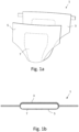
- FIG. 1a An example of a wearable absorbent article 1, in which the printed material webs of the present disclosure can be used, is shown in Fig. 1a and in cross in Fig. 1b .
- the example shown is in the form of an open diaper 1.
- other types of absorbent articles could be the above-mentioned types, e.g. pant-type diapers, sanitary napkins, panty liners, and incontinence protection articles such as incontinence pads.
- the absorbent article could be a wound care product (not shown).
- the absorbent article 1 typically comprises a liquid-permeable topsheet 3, a backsheet 5 and an absorbent body 7 enclosed between the liquid-permeable topsheet 3 and the backsheet 5.
- the liquid permeable topsheet 3 faces the wearer's body during use and is arranged to absorb body liquids such as urine and blood.
- the material of the topsheet 3 may e.g. comprise a nonwoven material of spunbond type, a meltblown material etc, and may be comprise several types of materials.
- the topsheet may comprise topsheet materials having different thicknesses.
- the backsheet 5 is typically liquid-impermeable, optionally breathable and may e.g. comprise a plastic (e.g. polyolefin) film, a plastic coated nonwoven or a hydrophobic nonwoven, and may also comprise a combination of different materials, which may have different thicknesses. Any one of the topsheet, backsheet and the core may comprise a printed image or pattern, and may thus be printed by the printing device or by using the printing method of the present disclosure.
- the absorbent body 7 acts to receive and contain liquid and other bodily exudates.
- the absorbent article contains absorbent materials. Examples of commonly occurring absorbent materials are cellulosic fluff pulp, tissue layers, superabsorbent polymers, absorbent foam materials, absorbent nonwoven materials or the like.
- the absorbent body 7 may be constructed from several layers, such as a liquid acquisition or distribution layer or a storage layer in order to fulfil functions which are desired for an absorbent body; i.e. capacity to quickly receive liquid, distribute it within the body and store it.
- the layers of the absorbent body are designed to receive a large amount of liquid in a short time and distribute it evenly across the absorbent body.
- the size and absorbent capacity of the absorbent body may be varied to be suited for different uses such as for baby diapers, sanitary napkins and incontinence pads.
- Various parts of the absorbent article may include a printed image or pattern, such as the backsheet, topsheet and the core.
- Wearable absorbent articles may comprise further parts to improve the fit or to assist the attachment of the article to the user, such as wings, leg cuffs, waist elastics or a waist portion, a fastening system, a landing zone, side panels, handles, fastening tabs, a pocket, spacers, or combinations thereof (not shown).
- Each of these parts may include a printed image or pattern.
- the material webs to be printed according to the present disclosure includes various types of materials, such as nonwoven materials and plastic films, such as plastic films of PE (polyethylene) or PP (polypropylene), PET (polyethylene terephthalate), PLA (polylactic acid) and/or amyl, or, for that matter, any other thermoplastic polymer, or a mixture or copolymers of the aforementioned polymers.
- the material web may also be a laminate comprising at least two or more material layers of the above-mentioned type.
- nonwoven material refers to a primarily fibrous assembly, which has structural integrity obtained by mechanical interlocking or by fusing fibers or by bonding by means of a cementing medium, such as starch the fibers. Thus, no weaving and/or knitting are/is involved. Also, the nonwoven is other than a traditional paper, woven, or knit. Nonwoven materials can be produced from the binding of natural and/or synthetic fibers, and are materials such as spun-bonded, SMS (spun bond, melt blown spun bond), SSMS, SMMS, carded, hydroentangled, spun laced, ultrasonically welded, as well as nonwovens made out of nanofibers, polypropylene tow, spunmelt highloft and the like.
- the nonwoven material may be also an airlaid material, meaning that a web of separated fibers or staple fibers is produced by laying the fibres on a wire and by forming a web in the presence of an airstream.
- the web may be bonded by using e.g. thermal resins.
- other types of nonwoven material may be included, particularly those that may be applied as an inner or outer layer of an absorbent article or garment.
- the grammage of the nonwoven material is in the range of 1-100 gsm (grams per square meter). However, this range may be more or less, depending on application and design preference.
- the material web may consist or comprise of other materials present in an absorbent article.
- the material web to be printed may be a spunlace, also referred to as spunbond, nonwoven material.
- a spunlace nonwoven product is derived from a process of entangling a web of loose fibres through multiple rows of jets of water at high pressure; this process entangles the fabrics and interlinks the fibres.
- spunlace nonwoven fabric or spunlaced such as jet entangled, needled, hydroentangled or hydraulic, but the term spunlace or spunlaced is the most popular in the nonwoven industry.
- the raw material for spunlace web material can be polypropylene (PP), polyethylene (PE) polyester (PET), polyamide (PA), cellulosic fibres or a combination of these and different weights and compositions are possible, such as viscose, polyester, cotton, nylon and microfibre, wherein viscose is the most commonly used raw material.
- PP polypropylene
- PE polyethylene
- PET PET
- PA polyamide
- cellulosic fibres or a combination of these and different weights and compositions are possible, such as viscose, polyester, cotton, nylon and microfibre, wherein viscose is the most commonly used raw material.
- PP/PE bi-component fibres or PP/PE copolymers e.g. PP/PE bi-component fibres or PP/PE copolymers.
- the spunlace material usually comprises polypropylene or polyethylene fibres which provide for optimal comfort for the nonwoven material.
- nonwoven material suitable fibres for making the nonwoven material are for example natural fibres such as bamboo, cotton and flax.
- the grammage of the spunlace nonwoven material can be typically from 25-120 gsm or from 40-90 gsm.
- the thickness of the material may vary of from 0.1 to 3 mm, such as 0.3 to 2.5 mm.
- One type of the material web to be printed may be high loft nonwoven, which may be a spunmelt nonwoven.
- Spunmelt is a generic term describing the manufacturing of nonwoven webs directly from thermoplastic polymers. It encompasses two processes and the combination of both: spunlaid (also known as spunbond) nonwoven and meltblown nonwoven.
- spunlaid also known as spunbond
- meltblown nonwoven meltblown nonwoven.
- spunlaid process polymer granules are melted and molten polymer is extruded through spinnerets.
- the continuous filaments are cooled and deposited on to a conveyor to form a uniform web. Some remaining temperature can cause filaments to adhere to one another, but this cannot be regarded as the principal method of bonding.
- the spunlaid process has the advantage of giving nonwovens greater strength, but raw material flexibility is more restricted.
- Co-extrusion of second components is used in several spunlaid processes, usually to provide extra properties or bonding capabilities.
- low viscosity polymers are extruded into a high velocity airstream on leaving the spinneret. This scatters the melt, solidifies it and breaks it up into a fibrous web.
- the liquid acquisition sheet material may be of a spunbonded material and may be a spunbond- meltbond-spunbond (SMS) material.
- SMS spunbond- meltbond-spunbond
- the high loft nonwoven layer may in particular have a thickness ranging from 0.3 mm to 4.0 mm, for example 1.0 mm as measured at a pressure of 0.5 kPa (according to the test method described further below).
- the grammage, i.e. basis weight of the high loft material may for example range from 15 gsm to 500 gsm, in particular from 30 gsm to 200 gsm, such as 30-90 gsm, for example 64 gsm.
- the material web to be printed may further be a carded nonwoven, which can be produced by means of airlaid process after fibers have been separated and aligned.
- the carded web can be bonded by means of one or more technologies used in connection with airlaid technology to provide integrity for the fabric.
- the material web can be an airlaid nonwoven which can be produced with fluff or wood pulp.
- the fluff fibres are dispersed into a fast mowing air stream and condensed onto a moving screen by means of pressure and vacuum.
- the web can be bonded with resin and/or thermal plastic resin dispersed within the pulp.
- the web can be thermobonded (by heat), latex bonded (with adhesive) or multibonded (a combination of thermo and latex bonding) or mechanically bonded (high compression and temperature, bonding by hydrogen).
- the grammage of the airlaid nonwoven can suitably be from 30-150 gsm or from 50 to 100 gsm.
- the thickness of the web can vary from 0.1 to 3 mm, such as from 0.5 to 2.5 mm.
- the material web to be printed may be aimed for use as a topsheet material, which normally lies in direct contact with the wearer's body.
- the topsheet material is preferably soft, comfortable and liquid-permeable.
- the topsheet can comprise any of the nonwoven materials discussed above and may be a combination of several types of material webs which are placed in different parts of the topsheet. Further examples of topsheet materials are porous foams, apertured plastic films etc.
- the topsheet may comprise different materials having different thicknesses.
- the present printing device comprising a printing unit configured for simultaneously printing at least two material webs having different thicknesses can be used for printing the topsheet material which has different thicknesses in different parts of the absorbent article.
- the backsheet lies in contact with the wearer's garments, and is liquid- impermeable.
- the backsheet refers to the liquid impervious material forming the outer cover of the absorbent article.
- the backsheet can comprise a thin plastic film, e.g. a polyethylene or polypropylene film, a nonwoven material coated with a liquid impervious material, a hydrophobic nonwoven material, which resists liquid penetration, or a laminate of a plastic film and a nonwoven material.
- Other laminate materials which are suitable for use as the backsheet are laminates of a nonwoven material and high loft material.
- the backsheet material may be breathable so as to allow vapour to escape from the absorbent core, while still preventing liquids from passing there through.
- breathable backsheet materials are porous polymeric films, nonwoven laminates of spunbond and meltblown layers and laminates of porous polymeric films and nonwoven materials.
- the backsheet comprises nonwoven material in at least the garment-facing surface thereof.
- the backsheet material may also comprise different materials having different thicknesses.
- the present printing device comprising a printing unit configured for simultaneously printing at least two material webs having different thicknesses can be used for printing the backsheet material which has different thicknesses in different parts of the absorbent article.
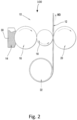
- a flexographic printing device 10 for printing on a continuous web of nonwoven material 12 is schematically shown in a side view.
- the device includes one printing unit 100, which includes a printing ink chamber14, an anilox roller 16, a print roller 18, and an impression roller 20.
- the printing device 10 may include several printing units, for example if multi-color printed designs are to be provided on the printing materials.
- the printing device of the present disclosure is configured to print at least two material webs having different thicknesses.
- the webs are fed between a print roller 18 and an impression roller 20 from a master roll 22, which is a storage roll, for a nonwoven material.
- the material web is fed in a machine direction (MD).
- MD machine direction
- the material webs are printed when the webs pass a printing nip formed between the printing roller, on which a printing cliché is mounted, and the impression roller.
- cliché which is also referred to as cliché or flexographic (flexo) printing plate
- a substrate a plate of polymeric rubber type or plastic material sheet, such as photopolymeric material, or an engraved metallic plate, which carriers the image to be printed.
- the image to be printed may also be provided an engraved printing sleeve or as an engraved printing roller.
- the plate used may have the image areas raised above the non-image areas.
- the thickness of the cliché may be for example within 0.5 to 4 mm, but is not limited thereto.
- the cliché is mounted on a printing roller and therefore the thicker the cliché is, the larger the radial extension of the cliché will be.
- the amount of clichés mounted on the printing roller can be varied, but at least one printing cliché is used to print one or several material webs.
- the cliché may have substantially the same radial extension over the whole area of the cliché.
- the thickness of the cliché and thus the radial extension of the cliché when mounted on the printing cylinder is adapted to the thickness of the material web to be printed.
- the cliché may have areas of different thicknesses adapted to the thickness of the material web to be printed.
- Each of the nonwoven material webs may comprise multiple layers of material and they may be fed from a feeding device.
- the feeding device may comprise at least one master roll, i.e. a storage roll containing the material web or webs to be printed, for the at least two material webs.
- the at least two material webs having different thicknesses may be attached to each other in a parallel manner in machine direction prior to the printing process, and thus the webs may be fed from a common master roll 22.
- the feeding device may comprise a respective master roll 22 for each of the material webs to be printed.
- the anilox roller 16 rotates in a clockwise (CW) direction and carriers ink 30 from the printing ink chamber14 to the print roller 18.
- the print roller 18 is disposed adjacent to the anilox roller 16 and rotates in a counterclockwise direction (CCW). Ink 30 from the anilox roller 16 is transferred to protruding graphic design portions on a printing cliché on the outer circumference of the print roller 18.
- the printing cliché mounted on the print roller 18 may include a removable sleeve, printing plate, or the like, for containing the particular design.
- the impression roller 20 which rotates in a clockwise (CW) direction, is disposed adjacent to the print roller 18 and on the opposite side of the material web 12, such that the cliché on the print roller 18 is pressed against and printed on the material web 12.
- CW clockwise
- the rollers may rotate in the opposite direction, so long as the rollers are appropriately coordinated.
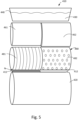
- the printing unit 210 comprises a printing ink chamber 240 for a printing ink 230, an anilox roller 260, which transfers the printing ink to the printing roller 280 comprising two printing clichés 281 and 282 and an impression roller 220, which presses towards the printing roller 280 during printing.
- the printing unit is configured for simultaneously printing at least two material webs 211, 212 having different thicknesses.
- the first material web 211 is thicker than the second material web 212.
- the radial extension of the at least one cliché 282, when mounted on the printing roller 280, is adapted in respect to the thickness of the thinner second material web 212 to be printed.
- the printing roller 280 contains an equal amount of clichés and material webs, i.e. two clichés 281 and 282, and two material webs 211 and 212.
- the clichés 281 and 282 have a radial extension adapted to the thickness of the respective material web to be printed, and thus the second cliché 282 and therefore has a larger radial extension than the first cliché 281.
- the larger radial extension may be provided by means of providing clichés having different thicknesses in a way corresponding to the different thicknesses of the material webs.
- the second cliché should compensate for the thickness difference of 0.1 mm in a corresponding way.
- the distance between the second material web 212 and the second cliché 282 will be close to the same as the distance between the first material web 211 and the second cliché 281.
- the nip pressure will be more equal along the axial extension of the printing roller than in case the clichés had a same radial extension.
- axial extension is meant the extension in a direction of the center axis of a roller, which has a substantially circular cylindrical shape. In the illustrated drawings, the axial extension is in the horizontal direction. In this way, the process control and resulting printing quality may be improved.
- the radial extension of the surface of the impression roller can be additionally or alternatively to the example described above be adapted in respect to the thickness of the material webs to be printed.
- Fig. 4 shows schematically an arrangement of such printing unit 310 in a flexographic printing device comprising a printing unit configured for simultaneously printing at least two material webs 311, 312 having different thicknesses.
- the printing unit 310 comprises a printing ink chamber 340 for a printing ink 330, an anilox roller 360, which transfers the printing ink to the printing roller 380 comprising two printing clichés 381 and 382. Alternatively only one large printing cliché with two separate printing patterns 381 and 382 could be used instead.
- the first material web 311 is thicker than the second material web 312.
- the printing unit comprises an impression roller 320 having two surface zones, a first surface zone 321 and a second surface zone 322, i.e. an equal amount of zones as there are material webs 311 and 312.
- the surface zones 321 and 322 have a radial extension adapted to the thickness of the respective material web 311 and 312 to be printed.
- the radial extension of the second surface zone 322 of the impression roller 320 is adapted in respect to the thickness of the thinner second material web 312 to be printed. More specifically, surface zones 321 and 322 have a radial extension adapted to the thickness of the respective material web to be printed, and thus the second surface zone 322 has a larger radial extension than the first surface zone 321.
- the larger radial extension may be provided by means of providing a covering means (not shown) to the impression cylinder 320.
- the covering means may be an elastic sheet, e.g. rubber sheet or a metallic sheet or folio.
- a covering means in the form of a cushioning means may be provided under a surface cover material of the impression cylinder 320. In this way a simple configuration of the printing unit can be made in a more permanent way, i.e. the cushioning means needs not to be changed in between different printing runs, if material webs with the same thickness difference are to be printed also in the next run.
- the larger radial extension can be provided by means of providing a thicker covering means over the zone adapted to print on the thinner material.
- the second surface zone should compensate for the thickness difference in a corresponding way. In this way, the distance between the second material web 312 and a cliché 382 mounted on the printing roller 380 is close to the same as the distance between the first material web 311 and the second cliché 381, when the impression cylinder 320 presses the webs 311 and 312 towards the printing roller 380 during the printing process.
- the nip pressure will be more equal along the axial extension of the printing roller than in a case where the surface of the impression cylinder 320 had a same radial extension. In this way, the process control and resulting printing quality may be maintained at a same level as if the material webs had the same thickness.
- a further example of a flexographic printing unit 410 in a flexographic printing device is shown which printing unit 410 is configured for simultaneously printing at least two material webs 411, 412 having different thicknesses.
- the embodiment shown could be an alternative to the above-mentioned embodiments or it could be used in combination with any one of the above-described embodiments.
- the first material web 411 is thicker than the second material web 412.
- the printing unit 410 comprises a printing ink chamber440 for a printing ink 430, and two anilox rollers 461, 462, which transfer the printing ink to the printing roller 480 comprising two printing clichés 481 and 482.
- the radial extension of the anilox roller 461 and anilox roller 462, respectively is adapted in respect to the thickness of the material web 411 and 412 to be printed.
- the printing unit 410 comprises an equal amount of anilox rollers and material webs, and each of the anilox rollers 461 and 462 has a radial extension adapted to the thickness of the respective material web 411, 412 to be printed.
- the anilox rollers 461, 462 may have substantially the same radius, but the radial position of each of the anilox rollers is adapted to the thickness of the respective material web to be printed. Thereby, the radial extension in respect of the material webs to be printed is adapted.
- the first anilox roller 461 is located at a larger distance from the first cliché 481 mounted on the printing roller 480, since it is adapted to feed ink 440 to the first cliché which prints on the first material web 411, which is thicker than the second material web 412.
- the anilox roller could be a single anilox roller as in connection with the embodiments shown in Fig. 3 and 4 .
- the anilox roller could be inclined in an axial direction, meaning that the anilox roller is tilted in respect of the center axis of the printing roller 480, which normally has its center axis parallel to the center axis of the anilox roller 460.
- inclined in axial direction is thus meant that a center axis of the anilox roller is inclined compared to a plane of the center axis of the printing roller.
- the printing device may comprise more than one printing unit as described above.
- the printing device there may be from 1 to 8 printing units as described above.
- the printing units may be configured to print different colors or coat the material web with a substance. If more than 8 units were needed, several printers could be positioned after each other, and in this way it would be feasible to have even more units in the printing process.
- the present disclosure also relates to a method of simultaneously printing at least two material webs having different thicknesses in a printing device comprising a printing unit as described above.
- the printing unit is adapted to print the webs by arranging:
- steps I, II and II may be performed as described above in connection with Fig. 3-5 .
- the at least one printing cliché may comprise a first printing pattern zone adapted to print on the first material web and a second printing pattern zone adapted to print on the second material web.
- a first printing cliché comprising a first printing pattern is configured to print on the first material web and a second printing cliché comprising a second printing pattern is configured to print on the second material web.
- more than two webs could be printed.
- three material webs can be printed.
- the method thus comprises printing on the three material webs having at least two different thicknesses, and wherein the printing roller comprises a printing cliché for the respective material web. All three material webs may have different thicknesses or two of the material webs may have the same thickness.
- the two outermost material webs may be thicker than the material web located between the outermost material webs. In this way it could be possible to provide a printed web suitable for use in an absorbent article as schematically shown in Fig. 6 and provide soft side edges for the article.
- the absorbent article comprises a topsheet comprising thicker side edge portions 611 with a first printed image 60.
- the middle section 612 of the article 61 comprises a thinner nonwoven material provided with a second printed image 70.
- the side edge portions 611 and the middle section of the topsheet are connected to each other, e.g. by means of gluing or welding the webs together.
- the first printed image 60 may be used to hide a connecting seam.
- the first material web and the second material web are simultaneously fed to the printing unit where a respective printing pattern on the respective first and second webs is printed.
- the first material web and the second material web may be separate webs, and wherein the method comprises feeding the webs from separate feeding devices or master rolls.
- the first material web and the second material web may be connected to each other in a parallel manner, such as by means of welding or gluing, and the method may thus comprise feeding the webs from a common feeding device comprising a common master roll.
- more than two material webs can be printed simultaneously. However, the amount of material webs to be printed simultaneously is preferably up to and including six material webs.
- the webs may be separate webs and the method may comprise feeding the webs from separate feeding devices.
- the three material webs may be connected to each other in a parallel manner, such as by means of welding or gluing, and the method comprises feeding the webs from a common feeding device.
- the printing patterns provided by the first and second clichés may be different from each other.
- the present disclosure also relates to the material web printed by the method as described above. Since the printing unit is adapted to the different material thicknesses, it is possible to provide a printed material web with equal printing quality in all webs.
- the material web may be a nonwoven, a plastic film, a woven material, a laminate or a combination thereof.
- the printed material web is used in a hygiene absorbent article comprising a topsheet, backsheet, an absorbent core between the topsheet and the backsheet, and optionally side panels, leg elastics, waist elastics and/or a belt.
Landscapes
- Engineering & Computer Science (AREA)
- Mechanical Engineering (AREA)
- Health & Medical Sciences (AREA)
- Animal Behavior & Ethology (AREA)
- Public Health (AREA)
- Heart & Thoracic Surgery (AREA)
- Vascular Medicine (AREA)
- Life Sciences & Earth Sciences (AREA)
- Epidemiology (AREA)
- General Health & Medical Sciences (AREA)
- Biomedical Technology (AREA)
- Veterinary Medicine (AREA)
- Printing Methods (AREA)
- Rotary Presses (AREA)
- Absorbent Articles And Supports Therefor (AREA)
- Inking, Control Or Cleaning Of Printing Machines (AREA)
- Making Paper Articles (AREA)
Claims (17)
- Flexodruckvorrichtung (10), die eine Druckeinheit (210; 310; 410) umfasst, die eine Druckwalze (18; 280; 380; 480), die auf einer ihrer Oberflächen ein zu druckendes Bild trägt, eine Gegendruckwalze (20; 220; 320; 420) und eine Aniloxwalze (16; 260; 360; 461, 462), die so eingerichtet ist, dass sie Druckfarbe aus einer Druckfarbenkammer (240; 340; 440) auf die Druckwalze zuführt, umfasst, dadurch gekennzeichnet, dass die Druckeinheit so konfiguriert ist, dass sie gleichzeitig mindestens zwei Materialbahnen (211, 212; 311, 312; 411, 412) bedruckt, die in Maschinenrichtung parallel angeordnet sind und unterschiedliche Dicken aufweisen, wobei die Materialbahnen bedruckt werden, wenn sie einen Druckspalt (N) passieren, der zwischen der Druckwalze und der Gegendruckwalze ausgebildet ist, und für jede Materialbahn eines oder mehreres gilt von:I. der radialen Umfang der Oberfläche der Druckwalze (18; 280; 380; 480), die das zu druckende Bild trägt, der jeweiligen Dicke der zu bedruckenden Materialbahn entspricht;II. der radialen Umfang der Oberfläche der Gegendruckwalze (20; 220; 320; 420) in Bezug auf jede Materialbahn der jeweiligen Dicke der zu bedruckenden Materialbahn entspricht; undIII. der radialen Umfang der Aniloxwalze (16; 260; 360; 461, 462) in Bezug auf jede Materialbahn der jeweiligen Dicke der zu bedruckenden Materialbahn entspricht.
- Flexodruckvorrichtung nach Anspruch 1, wobei das zu druckende Bild als Klischee bereitgestellt wird, das auf der Druckwalze (18; 280; 380; 480) montiert ist.
- Flexodruckvorrichtung nach Anspruch 2, wobei die Anzahl der Klischees (281, 282) gleich der Anzahl der Materialbahnen (211, 212) ist und wobei die Klischees jeweils einen radialen Umfang aufweisen, der der Dicke der jeweiligen zu bedruckenden Materialbahn entspricht.
- Flexodruckvorrichtung nach Anspruch 1, wobei das zu druckende Bild als gravierte Druckhülse oder als gravierte Druckwalze bereitgestellt wird.
- Flexodruckvorrichtung nach einem der vorhergehenden Ansprüche, wobei die Oberfläche der Gegendruckruckwalze (20; 220; 320; 420) eine gleiche Anzahl von Oberflächenzonen (321, 322) aufweist, wie es Materialbahnen (311, 312) gibt, und wobei die Zonen jeweils einen radialen Umfang aufweisen, der der Dicke der jeweiligen zu bedruckenden Materialbahn entspricht.
- Flexodruckvorrichtung nach einem der vorhergehenden Ansprüche, wobei die Aniloxwalze relativ zu einer Mittelachse der Druckwalze axial geneigt ist, so dass der radialen Umfang der Aniloxwalze der Dicke der jeweiligen zu bedruckenden Materialbahn entspricht.
- Flexodruckvorrichtung nach einem der vorstehenden Ansprüche 1 bis 5, wobei die Druckeinheit eine gleiche Anzahl von Aniloxwalzen (461, 462) umfasst, wie es Materialbahnen (411, 412) gibt, und wobei jede der Aniloxwalzen (461, 462) einen radialen Umfang aufweist, der der Dicke der jeweiligen zu bedruckenden Materialbahn (411, 412) entspricht.
- Flexodruckvorrichtung nach Anspruch 5, wobei die Zone oder Zonen (321, 322) der Druckwalze eine Abdeckung mit einem radialen Umfang aufweisen, der der Dicke der jeweiligen zu bedruckenden Materialbahn entspricht.
- Flexodruckvorrichtung nach einem der vorhergehenden Ansprüche, wobei die Vorrichtung ferner mindestens eine Zuführvorrichtung für die mindestens zwei Materialbahnen umfasst.
- Verfahren zum gleichzeitigen Bedrucken von mindestens zwei parallel in Maschinenrichtung angeordneten Materialbahnen mit unterschiedlichen Dicken in einer Druckvorrichtung nach einem der Ansprüche 1 bis 9, umfassend einen Schritt des Anpassens der Druckeinheit durch Anordnen für jede Materialbahn von einem oder mehreren von:I. der radialen Umfang der Oberfläche der Druckwalze (18; 280; 380; 480), die das zu druckende Bild trägt, so anzupassen, dass sie der jeweiligen Dicke der zu bedruckenden Materialbahn entspricht;II. die Oberfläche der Gegendruckwalze (20; 220; 320; 420) so anzupassen, dass der radialen Umfang entlang der Oberfläche der Gegendruckwalze der jeweiligen Dicke der zu bedruckenden Materialbahn entspricht; undIII. die Oberfläche der Aniloxwalze (16; 260; 360; 461, 462) so anzupassen, dass der radialen Umfang entlang der Oberfläche der Aniloxwalze der jeweiligen Dicke der zu bedruckenden Materialbahn entspricht, indem eine jeweilige Aniloxwalze relativ zur Materialbahn angeordnet wird und/oder indem die Aniloxwalze axial geneigt wird; undgleichzeitiges Zuführen der Materialbahnen zur Druckeinheit und Drucken eines jeweiligen Druckmusters auf die jeweiligen Bahnen.
- Verfahren nach Anspruch 10, wobei das zu druckende Bild in Form von mindestens einem Druckklischee, einer gravierten Druckhülse oder als gravierte Druckwalze bereitgestellt wird, die eine gleiche Anzahl von Druckmusterzonen wie die Anzahl der zu bedruckenden Materialbahnen umfasst.
- Verfahren nach Anspruch 10 oder 11, wobei das zu druckende Bild als Druckklischees bereitgestellt wird, wobei die Anzahl der Druckklischees der Anzahl der Materialbahnen entspricht, und wobei jedes Druckklischee so konfiguriert ist, dass es auf die jeweilige Materialbahn druckt.
- Verfahren gemäß einem der Ansprüche 10 - 12, wobei die Materialbahnen separate Bahnen sind und wobei das Verfahren das Zuführen der Bahnen von separaten Zuführvorrichtungen umfasst.
- Verfahren gemäß einem der Ansprüche 10 - 12, wobei die Materialbahnen parallel miteinander verbunden werden, beispielsweise durch Schweißen oder Kleben, und das Verfahren das Zuführen der Bahnen von einer gemeinsamen Zuführvorrichtung umfasst.
- Verfahren nach einem der Ansprüche 10 bis 14, wobei die Anzahl der Bahnen zwei beträgt.
- Verfahren nach einem der Ansprüche 10 bis 14, wobei die Anzahl der Bahnen drei beträgt und wobei zwei der drei Materialbahnen die gleiche Dicke aufweisen und eine der Bahnen dicker oder dünner ist als die beiden Bahnen mit der gleichen Dicke.
- Verfahren nach Anspruch 12, wobei die von den Klischees bereitgestellten Druckmuster voneinander verschieden sind.
Applications Claiming Priority (1)
| Application Number | Priority Date | Filing Date | Title |
|---|---|---|---|
| PCT/SE2018/050357 WO2019194710A1 (en) | 2018-04-05 | 2018-04-05 | Flexographic printing device and a method of simultaneously printing at least two material webs having different thicknesses |
Publications (4)
| Publication Number | Publication Date |
|---|---|
| EP3774342A1 EP3774342A1 (de) | 2021-02-17 |
| EP3774342A4 EP3774342A4 (de) | 2021-10-13 |
| EP3774342C0 EP3774342C0 (de) | 2025-03-26 |
| EP3774342B1 true EP3774342B1 (de) | 2025-03-26 |
Family
ID=68101557
Family Applications (1)
| Application Number | Title | Priority Date | Filing Date |
|---|---|---|---|
| EP18913317.6A Active EP3774342B1 (de) | 2018-04-05 | 2018-04-05 | Flexodruckvorrichtung und verfahren zum gleichzeitigen bedrucken von mindestens zwei materialbahnen mit unterschiedlichen dicken |
Country Status (11)
| Country | Link |
|---|---|
| US (1) | US11806986B2 (de) |
| EP (1) | EP3774342B1 (de) |
| JP (1) | JP7032559B2 (de) |
| CN (1) | CN111971179B (de) |
| AU (1) | AU2018417526B2 (de) |
| BR (1) | BR112020020062A2 (de) |
| CO (1) | CO2020012625A2 (de) |
| EC (1) | ECSP20069424A (de) |
| MX (1) | MX2020010453A (de) |
| RU (1) | RU2750096C1 (de) |
| WO (1) | WO2019194710A1 (de) |
Families Citing this family (1)
| Publication number | Priority date | Publication date | Assignee | Title |
|---|---|---|---|---|
| CN111971179B (zh) | 2018-04-05 | 2022-07-05 | 易希提卫生与保健公司 | 柔性版印刷装置和同时印刷至少两个材料幅的方法 |
Family Cites Families (40)
| Publication number | Priority date | Publication date | Assignee | Title |
|---|---|---|---|---|
| US562567A (en) | 1896-06-23 | Horseshoe | ||
| US1733707A (en) * | 1923-08-04 | 1929-10-29 | Wood Newspaper Mach Corp | Multiple-width printing press |
| US1763679A (en) * | 1926-03-27 | 1930-06-17 | Burnham C Stickney | Printing press |
| US3138097A (en) * | 1962-03-14 | 1964-06-23 | Harris Intertype Corp | Printing press and method |
| US4008661A (en) * | 1975-03-20 | 1977-02-22 | In-Line Equipment Company, Inc. | Printing press for use with bag-making machines |
| US4309945A (en) | 1978-04-03 | 1982-01-12 | Maryland Cup Corporation | Flexographic printing unit |
| FR2492734A1 (fr) * | 1980-10-29 | 1982-04-30 | Holweg Atel Const Meca C A | Procede et dispositif pour le positionnement des stations d'encrage d'une imprimeuse flexographique |
| ES8801885A2 (es) | 1985-12-23 | 1988-03-01 | Prospecciones Especiales S A | Sistema de aportacion de tinta a un cliche de flexografia |
| FR2656831A1 (fr) * | 1990-01-05 | 1991-07-12 | Boggy Sa | Groupe d'impression pour machine flexographique. |
| CH684070A5 (de) * | 1991-09-25 | 1994-07-15 | Escher Wyss Ag | Formzylinder einer Rotationsdruckmaschine. |
| SG54199A1 (en) | 1991-11-11 | 1998-11-16 | Procter & Gamble | Absorbent article with comfortable and rapid acquisition topsheet |
| US5636567A (en) * | 1996-05-31 | 1997-06-10 | Webtron Corporation | Printing press with web feed metering system |
| US5894799A (en) | 1997-10-01 | 1999-04-20 | E. I. Du Pont De Nemours And Company | Element for cushioning a flexographic printing plate |
| DE10024001B4 (de) | 2000-05-17 | 2014-11-13 | Manroland Web Systems Gmbh | Formatvariable Rollenoffsetdruckmaschine und Verfahren zur Herstellung formatvariabler Oberflächen |
| DE102004031645A1 (de) * | 2003-07-25 | 2005-02-10 | Heidelberger Druckmaschinen Ag | Aufzugsvorrichtung für hülsenförmige Aufzüge |
| US7367264B2 (en) * | 2004-07-30 | 2008-05-06 | Beaudry Wallace J | Method and apparatus for treating sheets including a vacuum roller for retaining sheets in curved configuration |
| DE102004056389B4 (de) * | 2004-09-16 | 2008-05-21 | Koenig & Bauer Aktiengesellschaft | Druckwerk einer Offsetdruckmaschine mit mindestens einem Formzylinder und einem Übertragungszylinder |
| CN101340877A (zh) | 2005-12-16 | 2009-01-07 | Sca卫生产品股份公司 | 吸收产品 |
| EP1803565A1 (de) * | 2005-12-27 | 2007-07-04 | Fischer & Krecke GmbH & Co. KG | Verfahren zum Druckwerkwechsel an einer laufenden Rotations-Druckmaschine |
| ITMI20061216A1 (it) * | 2006-06-23 | 2007-12-24 | Omet Srl | Macchina da stampa flessografica con dispositivo di asciugatura essicazione polimerizzazione e-o riscaldamento del nastro inchiostrato |
| DE102006046521A1 (de) * | 2006-09-29 | 2008-04-03 | Man Roland Druckmaschinen Ag | Druckwerk einer Druckmaschine |
| JP2008132721A (ja) * | 2006-11-29 | 2008-06-12 | Nitto Denko Corp | 印刷機用のクッションシート、印刷機、及び印刷方法 |
| US20090211475A1 (en) * | 2008-02-21 | 2009-08-27 | Taylor Bradley K | Extended print sleeve and method for preparing a printing form from the sleeve |
| NL2001608C2 (nl) * | 2008-05-22 | 2009-11-24 | Mps Holding B V | Drukmodule voor gebruik in een offsetdrukinrichting en offsetdrukinrichting voorzien van een dergelijke drukmodule. |
| US20100089264A1 (en) | 2008-10-10 | 2010-04-15 | Alrick Vincent Warner | Absorbent Articles Having Distinct Graphics And Apparatus And Method For Printing Such Absorbent Articles |
| US20100129620A1 (en) | 2008-11-25 | 2010-05-27 | Sca Hygiene Products Ab | Apparatus and method for printing on a material for use in absorbent articles |
| JP5959855B2 (ja) | 2008-12-22 | 2016-08-02 | テクノソリューションズ アッセスソリア リミターダ | ウェットオンウェット機能を有するフレキソ印刷プロセス |
| JP2012506331A (ja) | 2009-08-21 | 2012-03-15 | ザ プロクター アンド ギャンブル カンパニー | 別個の図柄及び同一図柄の両方を有する吸収性物品、及びかかる吸収性物品を印刷するための装置及び方法 |
| LU91741B1 (de) | 2010-09-24 | 2012-03-26 | Euro Composites | Mehrschichtige expandierbare Hülse für einen Druckmaschinenzylinder insbesondere für Flexodruck |
| DE102011108665A1 (de) * | 2011-07-27 | 2013-01-31 | Gallus Druckmaschinen Gmbh | Induktiv beheizbarer Zylinder |
| ES2402151B1 (es) | 2011-10-17 | 2014-02-28 | Miquel Y Costas & Miquel, S.A. | Procedimiento de impresión monocapa de papel para artículos de fumar. |
| EP2818319B1 (de) * | 2013-06-28 | 2015-08-05 | CONPRINTA GmbH & Co. KG | Druckwerk |
| US9492336B2 (en) * | 2013-10-18 | 2016-11-15 | The Procter & Gamble Company | Absorbent article having a composite web with visual signal thereon |
| JP6355499B2 (ja) * | 2014-09-25 | 2018-07-11 | 花王株式会社 | 展開型の使い捨ておむつ |
| JP6912155B2 (ja) * | 2014-10-20 | 2021-07-28 | 三菱重工機械システム株式会社 | フレキソ印刷機および製函機 |
| CN204184028U (zh) * | 2014-10-29 | 2015-03-04 | 云南恩典科技产业发展有限公司 | 一种多色混色印刷装置 |
| CN204566874U (zh) * | 2015-04-02 | 2015-08-19 | 濮阳市四季青塑料制品有限公司 | 农膜标记柔印机 |
| CN105252902A (zh) * | 2015-11-20 | 2016-01-20 | 浙江维涅斯装饰材料股份有限公司 | 一种柔版印刷装置 |
| ITUB20160533A1 (it) * | 2016-02-02 | 2017-08-02 | Trelleborg Coated Systems Italy S P A | Metodo per realizzare su una manica per stampa flessografica una guida per la posa e il taglio di un cliché e/o di uno strato biadesivo interposto tra la manica ed il cliché |
| CN111971179B (zh) | 2018-04-05 | 2022-07-05 | 易希提卫生与保健公司 | 柔性版印刷装置和同时印刷至少两个材料幅的方法 |
-
2018
- 2018-04-05 CN CN201880091979.4A patent/CN111971179B/zh active Active
- 2018-04-05 US US16/982,674 patent/US11806986B2/en active Active
- 2018-04-05 JP JP2020554149A patent/JP7032559B2/ja active Active
- 2018-04-05 RU RU2020135523A patent/RU2750096C1/ru active
- 2018-04-05 AU AU2018417526A patent/AU2018417526B2/en not_active Ceased
- 2018-04-05 MX MX2020010453A patent/MX2020010453A/es unknown
- 2018-04-05 WO PCT/SE2018/050357 patent/WO2019194710A1/en not_active Ceased
- 2018-04-05 EP EP18913317.6A patent/EP3774342B1/de active Active
- 2018-04-05 BR BR112020020062-0A patent/BR112020020062A2/pt not_active Application Discontinuation
-
2020
- 2020-10-09 CO CONC2020/0012625A patent/CO2020012625A2/es unknown
- 2020-10-29 EC ECSENADI202069424A patent/ECSP20069424A/es unknown
Also Published As
| Publication number | Publication date |
|---|---|
| BR112020020062A2 (pt) | 2021-01-05 |
| EP3774342A4 (de) | 2021-10-13 |
| CN111971179B (zh) | 2022-07-05 |
| WO2019194710A1 (en) | 2019-10-10 |
| ECSP20069424A (es) | 2020-11-30 |
| MX2020010453A (es) | 2020-10-20 |
| JP2021520305A (ja) | 2021-08-19 |
| US20210001619A1 (en) | 2021-01-07 |
| EP3774342C0 (de) | 2025-03-26 |
| CN111971179A (zh) | 2020-11-20 |
| AU2018417526A1 (en) | 2020-10-22 |
| US11806986B2 (en) | 2023-11-07 |
| EP3774342A1 (de) | 2021-02-17 |
| CO2020012625A2 (es) | 2020-10-30 |
| JP7032559B2 (ja) | 2022-03-08 |
| RU2750096C1 (ru) | 2021-06-22 |
| AU2018417526B2 (en) | 2022-07-21 |
Similar Documents
| Publication | Publication Date | Title |
|---|---|---|
| US6645330B2 (en) | Method of making disposable absorbent article having graphics using ultrasonic thermal imaging | |
| US20250387275A1 (en) | Elastomeric absorbent articles | |
| EP2842734B1 (de) | Verbundfolie und verfahren zur herstellung einer verbundfolie | |
| US8128771B2 (en) | Method of producing clothing article | |
| CN112118814A (zh) | 气流成网复合材料片材 | |
| JP6185155B2 (ja) | 改良された滑らかな柔軟性及び良好な強度特性を有する不織布ウェブ材料及び製造方法 | |
| KR20000034790A (ko) | 복합 탄성 물질 성형 방법 | |
| CN101772336A (zh) | 用于吸收性物品的底片 | |
| WO2000030818A1 (en) | Process and apparatus for making selectively apertured web materials | |
| CN110325678A (zh) | 层叠无纺布和其制造方法以及吸收性物品和吸汗片 | |
| CN111954513B (zh) | 用于吸收制品的纤维网及其制造方法 | |
| JP3719975B2 (ja) | 吸収体の製造方法 | |
| EP1873292B1 (de) | Mehrschichtiges und multikomponentes Vliesmaterial mit unterschiedlicher Faserdichte und Verfahren zu dessen Herstellung | |
| EP3774342B1 (de) | Flexodruckvorrichtung und verfahren zum gleichzeitigen bedrucken von mindestens zwei materialbahnen mit unterschiedlichen dicken | |
| TW201713295A (zh) | 吸收性物品及其製造方法(三) | |
| JP5691254B2 (ja) | 吸収性物品用積層シートの製造方法、吸収性物品用積層シート及び吸収性物品 | |
| KR20210002593A (ko) | 흡수 용품 | |
| EP4132443B1 (de) | Verfahren zur übertragung eines oder mehrerer ausgeschnittener vliesstoffelemente zur verwendung in einem saugfähigen artikel | |
| US12599507B2 (en) | Method and apparatus for manufacturing an elastic laminate and a disposable absorbent hygiene product comprising the elastic laminate | |
| UA126596C2 (uk) | Компонент всмоктувального виробу | |
| WO2005082618A1 (en) | Composit of absorbing sheet with visible holed film | |
| MXPA00005455A (en) | Absorbent articles |
Legal Events
| Date | Code | Title | Description |
|---|---|---|---|
| STAA | Information on the status of an ep patent application or granted ep patent |
Free format text: STATUS: THE INTERNATIONAL PUBLICATION HAS BEEN MADE |
|
| PUAI | Public reference made under article 153(3) epc to a published international application that has entered the european phase |
Free format text: ORIGINAL CODE: 0009012 |
|
| STAA | Information on the status of an ep patent application or granted ep patent |
Free format text: STATUS: REQUEST FOR EXAMINATION WAS MADE |
|
| 17P | Request for examination filed |
Effective date: 20201104 |
|
| AK | Designated contracting states |
Kind code of ref document: A1 Designated state(s): AL AT BE BG CH CY CZ DE DK EE ES FI FR GB GR HR HU IE IS IT LI LT LU LV MC MK MT NL NO PL PT RO RS SE SI SK SM TR |
|
| AX | Request for extension of the european patent |
Extension state: BA ME |
|
| DAV | Request for validation of the european patent (deleted) | ||
| DAX | Request for extension of the european patent (deleted) | ||
| A4 | Supplementary search report drawn up and despatched |
Effective date: 20210915 |
|
| RIC1 | Information provided on ipc code assigned before grant |
Ipc: B41F 13/18 20060101ALI20210909BHEP Ipc: B41F 13/10 20060101ALI20210909BHEP Ipc: B41M 1/04 20060101ALI20210909BHEP Ipc: A61F 13/84 20060101ALI20210909BHEP Ipc: B41F 5/24 20060101AFI20210909BHEP |
|
| STAA | Information on the status of an ep patent application or granted ep patent |
Free format text: STATUS: EXAMINATION IS IN PROGRESS |
|
| 17Q | First examination report despatched |
Effective date: 20240130 |
|
| GRAP | Despatch of communication of intention to grant a patent |
Free format text: ORIGINAL CODE: EPIDOSNIGR1 |
|
| STAA | Information on the status of an ep patent application or granted ep patent |
Free format text: STATUS: GRANT OF PATENT IS INTENDED |
|
| INTG | Intention to grant announced |
Effective date: 20241023 |
|
| GRAS | Grant fee paid |
Free format text: ORIGINAL CODE: EPIDOSNIGR3 |
|
| GRAA | (expected) grant |
Free format text: ORIGINAL CODE: 0009210 |
|
| STAA | Information on the status of an ep patent application or granted ep patent |
Free format text: STATUS: THE PATENT HAS BEEN GRANTED |
|
| AK | Designated contracting states |
Kind code of ref document: B1 Designated state(s): AL AT BE BG CH CY CZ DE DK EE ES FI FR GB GR HR HU IE IS IT LI LT LU LV MC MK MT NL NO PL PT RO RS SE SI SK SM TR |
|
| REG | Reference to a national code |
Ref country code: GB Ref legal event code: FG4D |
|
| REG | Reference to a national code |
Ref country code: CH Ref legal event code: EP |
|
| REG | Reference to a national code |
Ref country code: DE Ref legal event code: R096 Ref document number: 602018080599 Country of ref document: DE |
|
| REG | Reference to a national code |
Ref country code: IE Ref legal event code: FG4D |
|
| U01 | Request for unitary effect filed |
Effective date: 20250423 |
|
| U07 | Unitary effect registered |
Designated state(s): AT BE BG DE DK EE FI FR IT LT LU LV MT NL PT RO SE SI Effective date: 20250428 |
|
| U20 | Renewal fee for the european patent with unitary effect paid |
Year of fee payment: 8 Effective date: 20250429 |
|
| PG25 | Lapsed in a contracting state [announced via postgrant information from national office to epo] |
Ref country code: RS Free format text: LAPSE BECAUSE OF FAILURE TO SUBMIT A TRANSLATION OF THE DESCRIPTION OR TO PAY THE FEE WITHIN THE PRESCRIBED TIME-LIMIT Effective date: 20250626 |
|
| PG25 | Lapsed in a contracting state [announced via postgrant information from national office to epo] |
Ref country code: NO Free format text: LAPSE BECAUSE OF FAILURE TO SUBMIT A TRANSLATION OF THE DESCRIPTION OR TO PAY THE FEE WITHIN THE PRESCRIBED TIME-LIMIT Effective date: 20250626 |
|
| PG25 | Lapsed in a contracting state [announced via postgrant information from national office to epo] |
Ref country code: HR Free format text: LAPSE BECAUSE OF FAILURE TO SUBMIT A TRANSLATION OF THE DESCRIPTION OR TO PAY THE FEE WITHIN THE PRESCRIBED TIME-LIMIT Effective date: 20250326 |
|
| PG25 | Lapsed in a contracting state [announced via postgrant information from national office to epo] |
Ref country code: GR Free format text: LAPSE BECAUSE OF FAILURE TO SUBMIT A TRANSLATION OF THE DESCRIPTION OR TO PAY THE FEE WITHIN THE PRESCRIBED TIME-LIMIT Effective date: 20250627 |
|
| PG25 | Lapsed in a contracting state [announced via postgrant information from national office to epo] |
Ref country code: SM Free format text: LAPSE BECAUSE OF FAILURE TO SUBMIT A TRANSLATION OF THE DESCRIPTION OR TO PAY THE FEE WITHIN THE PRESCRIBED TIME-LIMIT Effective date: 20250326 |
|
| PG25 | Lapsed in a contracting state [announced via postgrant information from national office to epo] |
Ref country code: ES Free format text: LAPSE BECAUSE OF FAILURE TO SUBMIT A TRANSLATION OF THE DESCRIPTION OR TO PAY THE FEE WITHIN THE PRESCRIBED TIME-LIMIT Effective date: 20250326 |
|
| PG25 | Lapsed in a contracting state [announced via postgrant information from national office to epo] |
Ref country code: PL Free format text: LAPSE BECAUSE OF FAILURE TO SUBMIT A TRANSLATION OF THE DESCRIPTION OR TO PAY THE FEE WITHIN THE PRESCRIBED TIME-LIMIT Effective date: 20250326 |
|
| PG25 | Lapsed in a contracting state [announced via postgrant information from national office to epo] |
Ref country code: SK Free format text: LAPSE BECAUSE OF FAILURE TO SUBMIT A TRANSLATION OF THE DESCRIPTION OR TO PAY THE FEE WITHIN THE PRESCRIBED TIME-LIMIT Effective date: 20250326 |
|
| PG25 | Lapsed in a contracting state [announced via postgrant information from national office to epo] |
Ref country code: IS Free format text: LAPSE BECAUSE OF FAILURE TO SUBMIT A TRANSLATION OF THE DESCRIPTION OR TO PAY THE FEE WITHIN THE PRESCRIBED TIME-LIMIT Effective date: 20250726 |
|
| REG | Reference to a national code |
Ref country code: CH Ref legal event code: H13 Free format text: ST27 STATUS EVENT CODE: U-0-0-H10-H13 (AS PROVIDED BY THE NATIONAL OFFICE) Effective date: 20251125 |
|
| PG25 | Lapsed in a contracting state [announced via postgrant information from national office to epo] |
Ref country code: MC Free format text: LAPSE BECAUSE OF FAILURE TO SUBMIT A TRANSLATION OF THE DESCRIPTION OR TO PAY THE FEE WITHIN THE PRESCRIBED TIME-LIMIT Effective date: 20250326 |
|
| PG25 | Lapsed in a contracting state [announced via postgrant information from national office to epo] |
Ref country code: CH Free format text: LAPSE BECAUSE OF NON-PAYMENT OF DUE FEES Effective date: 20250430 |
|
| PG25 | Lapsed in a contracting state [announced via postgrant information from national office to epo] |
Ref country code: CZ Free format text: LAPSE BECAUSE OF FAILURE TO SUBMIT A TRANSLATION OF THE DESCRIPTION OR TO PAY THE FEE WITHIN THE PRESCRIBED TIME-LIMIT Effective date: 20250326 |
|
| PLBE | No opposition filed within time limit |
Free format text: ORIGINAL CODE: 0009261 |
|
| STAA | Information on the status of an ep patent application or granted ep patent |
Free format text: STATUS: NO OPPOSITION FILED WITHIN TIME LIMIT |
|
| REG | Reference to a national code |
Ref country code: CH Ref legal event code: L10 Free format text: ST27 STATUS EVENT CODE: U-0-0-L10-L00 (AS PROVIDED BY THE NATIONAL OFFICE) Effective date: 20260211 |
|
| GBPC | Gb: european patent ceased through non-payment of renewal fee |
Effective date: 20250626 |
|
| 26N | No opposition filed |
Effective date: 20260105 |
|
| PG25 | Lapsed in a contracting state [announced via postgrant information from national office to epo] |
Ref country code: GB Free format text: LAPSE BECAUSE OF NON-PAYMENT OF DUE FEES Effective date: 20250626 |
|
| PG25 | Lapsed in a contracting state [announced via postgrant information from national office to epo] |
Ref country code: IE Free format text: LAPSE BECAUSE OF NON-PAYMENT OF DUE FEES Effective date: 20250405 |