EP3773127B1 - Licht- oder bildleitkomponenten für einweg-endoskope - Google Patents
Licht- oder bildleitkomponenten für einweg-endoskope Download PDFInfo
- Publication number
- EP3773127B1 EP3773127B1 EP19714192.2A EP19714192A EP3773127B1 EP 3773127 B1 EP3773127 B1 EP 3773127B1 EP 19714192 A EP19714192 A EP 19714192A EP 3773127 B1 EP3773127 B1 EP 3773127B1
- Authority
- EP
- European Patent Office
- Prior art keywords
- plastics material
- cable
- light guide
- illumination light
- proximal
- Prior art date
- Legal status (The legal status is an assumption and is not a legal conclusion. Google has not performed a legal analysis and makes no representation as to the accuracy of the status listed.)
- Active
Links
Images


Classifications
-
- A—HUMAN NECESSITIES
- A61—MEDICAL OR VETERINARY SCIENCE; HYGIENE
- A61B—DIAGNOSIS; SURGERY; IDENTIFICATION
- A61B1/00—Instruments for performing medical examinations of the interior of cavities or tubes of the body by visual or photographical inspection, e.g. endoscopes; Illuminating arrangements therefor
- A61B1/00064—Constructional details of the endoscope body
- A61B1/00103—Constructional details of the endoscope body designed for single use
-
- A—HUMAN NECESSITIES
- A61—MEDICAL OR VETERINARY SCIENCE; HYGIENE
- A61B—DIAGNOSIS; SURGERY; IDENTIFICATION
- A61B1/00—Instruments for performing medical examinations of the interior of cavities or tubes of the body by visual or photographical inspection, e.g. endoscopes; Illuminating arrangements therefor
- A61B1/00064—Constructional details of the endoscope body
- A61B1/00071—Insertion part of the endoscope body
- A61B1/0008—Insertion part of the endoscope body characterised by distal tip features
- A61B1/00096—Optical elements
-
- A—HUMAN NECESSITIES
- A61—MEDICAL OR VETERINARY SCIENCE; HYGIENE
- A61B—DIAGNOSIS; SURGERY; IDENTIFICATION
- A61B1/00—Instruments for performing medical examinations of the interior of cavities or tubes of the body by visual or photographical inspection, e.g. endoscopes; Illuminating arrangements therefor
- A61B1/00064—Constructional details of the endoscope body
- A61B1/0011—Manufacturing of endoscope parts
-
- A—HUMAN NECESSITIES
- A61—MEDICAL OR VETERINARY SCIENCE; HYGIENE
- A61B—DIAGNOSIS; SURGERY; IDENTIFICATION
- A61B1/00—Instruments for performing medical examinations of the interior of cavities or tubes of the body by visual or photographical inspection, e.g. endoscopes; Illuminating arrangements therefor
- A61B1/00112—Connection or coupling means
- A61B1/00117—Optical cables in or with an endoscope
-
- A—HUMAN NECESSITIES
- A61—MEDICAL OR VETERINARY SCIENCE; HYGIENE
- A61B—DIAGNOSIS; SURGERY; IDENTIFICATION
- A61B1/00—Instruments for performing medical examinations of the interior of cavities or tubes of the body by visual or photographical inspection, e.g. endoscopes; Illuminating arrangements therefor
- A61B1/00112—Connection or coupling means
- A61B1/00121—Connectors, fasteners and adapters, e.g. on the endoscope handle
- A61B1/00126—Connectors, fasteners and adapters, e.g. on the endoscope handle optical, e.g. for light supply cables
-
- A—HUMAN NECESSITIES
- A61—MEDICAL OR VETERINARY SCIENCE; HYGIENE
- A61B—DIAGNOSIS; SURGERY; IDENTIFICATION
- A61B1/00—Instruments for performing medical examinations of the interior of cavities or tubes of the body by visual or photographical inspection, e.g. endoscopes; Illuminating arrangements therefor
- A61B1/00163—Optical arrangements
- A61B1/00165—Optical arrangements with light-conductive means, e.g. fibre optics
- A61B1/00167—Details of optical fibre bundles, e.g. shape or fibre distribution
-
- A—HUMAN NECESSITIES
- A61—MEDICAL OR VETERINARY SCIENCE; HYGIENE
- A61B—DIAGNOSIS; SURGERY; IDENTIFICATION
- A61B1/00—Instruments for performing medical examinations of the interior of cavities or tubes of the body by visual or photographical inspection, e.g. endoscopes; Illuminating arrangements therefor
- A61B1/00163—Optical arrangements
- A61B1/00165—Optical arrangements with light-conductive means, e.g. fibre optics
- A61B1/0017—Details of single optical fibres, e.g. material or cladding
-
- A—HUMAN NECESSITIES
- A61—MEDICAL OR VETERINARY SCIENCE; HYGIENE
- A61B—DIAGNOSIS; SURGERY; IDENTIFICATION
- A61B1/00—Instruments for performing medical examinations of the interior of cavities or tubes of the body by visual or photographical inspection, e.g. endoscopes; Illuminating arrangements therefor
- A61B1/06—Instruments for performing medical examinations of the interior of cavities or tubes of the body by visual or photographical inspection, e.g. endoscopes; Illuminating arrangements therefor with illuminating arrangements
- A61B1/07—Instruments for performing medical examinations of the interior of cavities or tubes of the body by visual or photographical inspection, e.g. endoscopes; Illuminating arrangements therefor with illuminating arrangements using light-conductive means, e.g. optical fibres
-
- B—PERFORMING OPERATIONS; TRANSPORTING
- B29—WORKING OF PLASTICS; WORKING OF SUBSTANCES IN A PLASTIC STATE IN GENERAL
- B29C—SHAPING OR JOINING OF PLASTICS; SHAPING OF MATERIAL IN A PLASTIC STATE, NOT OTHERWISE PROVIDED FOR; AFTER-TREATMENT OF THE SHAPED PRODUCTS, e.g. REPAIRING
- B29C45/00—Injection moulding, i.e. forcing the required volume of moulding material through a nozzle into a closed mould; Apparatus therefor
- B29C45/14—Injection moulding, i.e. forcing the required volume of moulding material through a nozzle into a closed mould; Apparatus therefor incorporating preformed parts or layers, e.g. injection moulding around inserts or for coating articles
- B29C45/14336—Coating a portion of the article, e.g. the edge of the article
- B29C45/14426—Coating the end of wire-like or rod-like or cable-like or blade-like or belt-like articles
-
- B—PERFORMING OPERATIONS; TRANSPORTING
- B29—WORKING OF PLASTICS; WORKING OF SUBSTANCES IN A PLASTIC STATE IN GENERAL
- B29D—PRODUCING PARTICULAR ARTICLES FROM PLASTICS OR FROM SUBSTANCES IN A PLASTIC STATE
- B29D11/00—Producing optical elements, e.g. lenses or prisms
- B29D11/00663—Production of light guides
-
- G—PHYSICS
- G02—OPTICS
- G02B—OPTICAL ELEMENTS, SYSTEMS OR APPARATUS
- G02B23/00—Telescopes, e.g. binoculars; Periscopes; Instruments for viewing the inside of hollow bodies; Viewfinders; Optical aiming or sighting devices
- G02B23/24—Instruments or systems for viewing the inside of hollow bodies, e.g. fibrescopes
- G02B23/2407—Optical details
- G02B23/2461—Illumination
- G02B23/2469—Illumination using optical fibres
-
- G—PHYSICS
- G02—OPTICS
- G02B—OPTICAL ELEMENTS, SYSTEMS OR APPARATUS
- G02B23/00—Telescopes, e.g. binoculars; Periscopes; Instruments for viewing the inside of hollow bodies; Viewfinders; Optical aiming or sighting devices
- G02B23/24—Instruments or systems for viewing the inside of hollow bodies, e.g. fibrescopes
- G02B23/26—Instruments or systems for viewing the inside of hollow bodies, e.g. fibrescopes using light guides
-
- G—PHYSICS
- G02—OPTICS
- G02B—OPTICAL ELEMENTS, SYSTEMS OR APPARATUS
- G02B6/00—Light guides; Structural details of arrangements comprising light guides and other optical elements, e.g. couplings
- G02B6/0001—Light guides; Structural details of arrangements comprising light guides and other optical elements, e.g. couplings specially adapted for lighting devices or systems
- G02B6/0005—Light guides; Structural details of arrangements comprising light guides and other optical elements, e.g. couplings specially adapted for lighting devices or systems the light guides being of the fibre type
- G02B6/0006—Coupling light into the fibre
-
- G—PHYSICS
- G02—OPTICS
- G02B—OPTICAL ELEMENTS, SYSTEMS OR APPARATUS
- G02B6/00—Light guides; Structural details of arrangements comprising light guides and other optical elements, e.g. couplings
- G02B6/0001—Light guides; Structural details of arrangements comprising light guides and other optical elements, e.g. couplings specially adapted for lighting devices or systems
- G02B6/0005—Light guides; Structural details of arrangements comprising light guides and other optical elements, e.g. couplings specially adapted for lighting devices or systems the light guides being of the fibre type
- G02B6/0008—Light guides; Structural details of arrangements comprising light guides and other optical elements, e.g. couplings specially adapted for lighting devices or systems the light guides being of the fibre type the light being emitted at the end of the fibre
-
- G—PHYSICS
- G02—OPTICS
- G02B—OPTICAL ELEMENTS, SYSTEMS OR APPARATUS
- G02B6/00—Light guides; Structural details of arrangements comprising light guides and other optical elements, e.g. couplings
- G02B6/04—Light guides; Structural details of arrangements comprising light guides and other optical elements, e.g. couplings formed by bundles of fibres
- G02B6/06—Light guides; Structural details of arrangements comprising light guides and other optical elements, e.g. couplings formed by bundles of fibres the relative position of the fibres being the same at both ends, e.g. for transporting images
-
- G—PHYSICS
- G02—OPTICS
- G02B—OPTICAL ELEMENTS, SYSTEMS OR APPARATUS
- G02B6/00—Light guides; Structural details of arrangements comprising light guides and other optical elements, e.g. couplings
- G02B6/24—Coupling light guides
- G02B6/36—Mechanical coupling means
- G02B6/3616—Holders, macro size fixtures for mechanically holding or positioning fibres, e.g. on an optical bench
- G02B6/3624—Fibre head, e.g. fibre probe termination
-
- B—PERFORMING OPERATIONS; TRANSPORTING
- B29—WORKING OF PLASTICS; WORKING OF SUBSTANCES IN A PLASTIC STATE IN GENERAL
- B29K—INDEXING SCHEME ASSOCIATED WITH SUBCLASSES B29B, B29C OR B29D, RELATING TO MOULDING MATERIALS OR TO MATERIALS FOR MOULDS, REINFORCEMENTS, FILLERS OR PREFORMED PARTS, e.g. INSERTS
- B29K2995/00—Properties of moulding materials, reinforcements, fillers, preformed parts or moulds
- B29K2995/0018—Properties of moulding materials, reinforcements, fillers, preformed parts or moulds having particular optical properties, e.g. fluorescent or phosphorescent
- B29K2995/0026—Transparent
-
- G—PHYSICS
- G02—OPTICS
- G02B—OPTICAL ELEMENTS, SYSTEMS OR APPARATUS
- G02B6/00—Light guides; Structural details of arrangements comprising light guides and other optical elements, e.g. couplings
- G02B6/04—Light guides; Structural details of arrangements comprising light guides and other optical elements, e.g. couplings formed by bundles of fibres
-
- G—PHYSICS
- G02—OPTICS
- G02B—OPTICAL ELEMENTS, SYSTEMS OR APPARATUS
- G02B6/00—Light guides; Structural details of arrangements comprising light guides and other optical elements, e.g. couplings
- G02B6/24—Coupling light guides
- G02B6/26—Optical coupling means
- G02B6/262—Optical details of coupling light into, or out of, or between fibre ends, e.g. special fibre end shapes or associated optical elements
-
- G—PHYSICS
- G02—OPTICS
- G02B—OPTICAL ELEMENTS, SYSTEMS OR APPARATUS
- G02B6/00—Light guides; Structural details of arrangements comprising light guides and other optical elements, e.g. couplings
- G02B6/24—Coupling light guides
- G02B6/26—Optical coupling means
- G02B6/32—Optical coupling means having lens focusing means positioned between opposed fibre ends
- G02B6/325—Optical coupling means having lens focusing means positioned between opposed fibre ends comprising a transparent member, e.g. window, protective plate
Definitions
- the invention is defined by claim 1 and relates to a diagnostic, surgical and/or therapeutic device for introduction into the human or animal body or for in-vitro examination of human or animal blood samples or other body cells, in particular an endoscope or a disposable endoscope, containing at least one illumination light guide and/or image guide for transmitting electromagnetic radiation, wherein the illumination light guide or the image guide each have a proximal end face for coupling in or out electromagnetic radiation and a distal end face for coupling in or out electromagnetic radiation.
- Endoscopes for diagnosis, minimally invasive procedures or therapy are known as rigid or flexible versions and are adequately described in the literature.
- Disposable endoscopes are increasingly used today to increase patient safety in medical examinations, therapies and/or minimally invasive procedures by preventing contamination through single-use.
- Endoscopes to date have been designed to be reprocessable in the sense of medical technology, i.e. cleanable, sterilizable and, above all, autoclavable.
- Another aspect for the increased use of disposable endoscopes is also an economic consideration.
- the proper and regular reprocessing process after each treatment requires high costs for the practicing doctor or in the clinic.
- high investments are required for cleaning equipment, such as thermodisinfectors, and autoclaving devices and/or plasma sterilization devices, so that overall the use of such disposable endoscopes is justified.
- a further advantage is that such disposable endoscopes can be used as mobile hand-held devices and can therefore also be used in emergency medicine, in military medical operations or in regions that are difficult to access, for example in disaster relief operations, where no reprocessing options are available.
- the writing US3581738 A1 discloses a disposable endoscope comprising a body of synthetic resin material having a generally tubular side wall forming a speculum and a unitary elongated light guiding element embedded in the side wall, the element being formed of a light guiding material coated with a transparent material having a refractive index different from that of the light guiding material, the body being formed of two mating halves split axially from the endoscope, each half having an element enclosing element.
- US4964710A1 describes a rigid endoscope which is equipped with an objective system, an eyepiece lens and an intermediate relay lens.
- the relay system is a hybrid system which uses both plastic and glass elements.
- the plastic elements consist of a uniform plurality (N) of axially aligned lenses, each of which has a length in the same order as its diameter.
- the plastic lenses are a plurality (N minus 1) of axially aligned glass flat cylinders whose end faces are polished.
- the writing EP1890173A1 describes a method for producing a light guide as can be used in such endoscopes.
- a plurality of optical fibers are bundled and then the fiber bundle is cut at a part of a mouthpiece which is attached to an intermediate part of the fiber bundle.
- the fiber bundle is divided into a first optical fiber bundle and a second optical fiber bundle.
- the dividing surfaces of the first and second optical fiber bundles have the same properties and conditions because the first and second optical fiber bundles are formed from the fiber bundle obtained by bundling the same optical fibers.
- the first optical fiber bundle is mounted in an insertion section of an endoscope and the second optical fiber bundle is mounted in a flexible tube, whereby a first light guide is formed in the insertion section of the endoscope and a second light guide is formed in the flexible tube. This creates a separable light transmission path of the light guide.
- the assemblies and components must be manufactured in a cost-optimized manner.
- One of the main components for imaging and lighting is the illumination light guide or image guide. These are currently assembled or processed in comparatively complex process steps. Often it is complex mechanical components, sometimes combined with optical elements such as lenses, that contain these light guides or image guides, and sometimes it is also complex processing steps such as grinding and polishing the end surface that make current illumination light guides or image guides comparatively expensive.
- certain lighting requirements must also be taken into account when used for endoscopy, particularly in medical technology. In addition to providing the light provided by a light source to the examination site with as little loss as possible, color-accurate or targeted color representation of the examination site, and also avoiding the introduction of unnecessary heat into the examination site.
- biocompatibility requirements In addition to these lighting and electrical requirements, biocompatibility requirements must also be observed. For biocompatibility, it is necessary to ensure that the material is compatible with the human organism. For medical devices that can come into contact with the human body, regulatory requirements require that possible interactions and undesirable side effects be determined and evaluated. The choice of required tests depends on the type and duration of contact in the human body. According to the European Medical Devices Directive MDD 93/42 EEC, this biological assessment of a product is always necessary when there is direct contact between the material/product and the patient.
- Another advantage of designing the endoscopes as disposable endoscopes is that the cleaning/disinfection processes with strongly alkaline solutions and sterilization by autoclaving at temperatures of up to 135° C and typical steam pressures of around 3 bar, which are known as reprocessing methods, do not have to be taken into account to such an extent when selecting materials, which also allows for a more cost-effective selection of materials. Only RoHS and REACH regulations need to be taken into account when selecting materials.
- the object of the invention is therefore to provide illumination light guides or image guides for disposable endoscopes or assemblies with illumination light guides, image guides and/or cameras, which are particularly cost-effective to manufacture and on the other hand enable typical lighting requirements for endoscopes in medical technology, in particular high transmission and high color fidelity. This with high biocompatibility and low cytotoxicity in accordance with the medical technology requirements and effects.
- the object of the invention is achieved in that the proximal and/or distal end surfaces consist of at least partially or sectionally transparent plastic elements or a transparent plastic is molded onto them, the transparent plastic having biocompatible and/or non-toxic properties for human or animal cell cultures for exposure times of less than one day.
- This makes it possible to produce illumination light guides or image guides very cost-effectively, in which otherwise complex end processing, i.e. grinding and polishing of the proximal or distal end surfaces, can be omitted.
- the biocompatibility or the non-toxic properties of the plastics allow invasive intervention in the body (in vivo) or enable in-vitro examinations on cell cultures or blood samples without damaging or changing them.
- Suitable plastics are plastics made of at least one of the material classes cyclo-olefin copolymers, polycarbonates, polyethylene terephthalates, perfluoroalkoxy polymers, polyvinylidene fluorides, polymethyl methacrylates, polymethyl methacrylimides, acrylic-styrene-acrylonitrile copolymers or room temperature crosslinking silicone, hot-crosslinking liquid silicones, epoxy casting resins or adhesives, thermally or UV-crosslinking acrylate casting resins, polyurethane casting resins, polyester casting resins or mixtures and/or combinations thereof.
- Thermoplastics that are easy to injection mold and transparent, for example PC, PMMA, COC, etc., are particularly suitable, but also plastics that can be applied as casting resins. This makes it possible to create correspondingly smooth surfaces with a very low roughness value.
- the above-mentioned plastics are available as a biocompatible version.
- the proximal and/or distal end surface also each has a mechanical interface in the form of a sleeve contour, which is made of plastic or is molded onto the illumination light guide or image guide by means of plastic injection molding, whereby this plastic can differ from the transparent plastic of the proximal or distal end surface at least partially or in sections in terms of material, transparency and/or color.
- this plastic can differ from the transparent plastic of the proximal or distal end surface at least partially or in sections in terms of material, transparency and/or color.
- collars or shoulders, but also undercut areas can be created with which the illumination light guide or the image guide can be connected to a handpiece and/or a shaft of the endoscope.
- this can also be used to create snap-in connections that enable quick assembly, which in turn can reduce manufacturing costs.
- the transparent plastic of the proximal and/or distal end surfaces has a typical surface roughness Ra of ⁇ 1.0 ⁇ m, preferably ⁇ 0.5 ⁇ m, particularly preferably ⁇ 0.1 ⁇ m. This minimizes scattering losses on the surface, which would otherwise lead to a reduction in the illuminance at Illumination light guides. With image guides, a sharp image of the illuminated object can be achieved.
- the transparent plastic of the proximal or distal end surfaces has a refractive index that essentially corresponds to that of the core material of the fibers or fiber components used in the illumination light guide or image guide, reflection losses can be minimized, which leads to an increase in the illuminance of the illumination light guides and suppresses artifacts due to reflections in image guides.
- the deviation between the refractive index of the fibers or fiber components and the clear transparent plastic is a maximum of ⁇ 0.1, good results can already be achieved. With a maximum deviation of ⁇ 0.05, the refractive indices are already almost perfectly matched, so that the reflection losses in the illumination light guides can be neglected. In the case of image guides, ghost images due to multiple reflections in particular can be excluded.
- the illumination light guides and/or image guides for endoscopes comprise fiber bundles made of glass fibers, quartz fibers or plastic fibers.
- Glass fibers are particularly suitable for transmitting light or image information in the visible spectral range up to the near IR range.
- plastic fibers although the application length of the plastic fibers is typically limited to a few centimeters up to a maximum of 1 m.
- Quartz fibers are used in particular when the application wavelength extends into the IR range up to typically 2.2 ⁇ m or when light components in the near UV range, below about 400 nm, are to be used. This is of particular interest in fluorescence applications. It is particularly advantageous if the bundles or individual fibers are at least partially or sectionally surrounded by a sheath, hose, shrink tubing or mesh tubing or are protected by a shaft of the endoscope. This increases the mechanical robustness of the system.
- the jacket can be made of another plastic material and designed as an extruded cable. Such cables can be manufactured particularly cost-effectively in a continuous process.
- cost-effective, less temperature-stable plastics can be used for both the cable and the sleeves in the above-mentioned versions, since no thermal/chemical processing processes, such as autoclaving (typically 130 to 140°C in saturated steam) and/or thermo-disinfector processes (up to 95°C, cleaning agent with pH 11) are required for single-use applications.
- thermal/chemical processing processes such as autoclaving (typically 130 to 140°C in saturated steam) and/or thermo-disinfector processes (up to 95°C, cleaning agent with pH 11) are required for single-use applications.
- ethylene oxide fumigation or, in some cases, plasma-based gas sterilization STERAD, with hydrogen peroxide and plasma, or STERIS, with hydrogen peroxide only
- STERAD with hydrogen peroxide and plasma
- STERIS STERIS
- the plastic for the extruded sheath can consist of a plastic that is at least partially or partially translucent, opaque or colored. This can be used, for example, to provide lateral illumination on the endoscope using a laterally emitting optical fiber.
- the illumination light guide or image guide is made of flexible or semi-flexible fiber bundles and the sheath is at least partially or sectionally designed as a rigid sheath, a shaft for a rigid endoscope can be realized.
- the invention also relates to rigid fiber optic light or image guides, for example in the form of drawn fiber rods or in the form of pressed fiber rods, which are also advantageously based on the same glass systems as are used for corresponding flexible fiber optic bundles.
- optical elements and/or sleeves can be formed cost-effectively using a plastic cap molded directly onto the proximal and/or distal end of the light guide.
- the glass fibers, fiber rods or pressed fiber rods consist of a Pb- or heavy metal-free core glass and cladding glass.
- Such fiber systems offer a high transmission in the VIS spectral range in particular and, due to the comparatively high transmission in the blue spectral range, show a high color fidelity, which is particularly important in the medical assessment of tissue. Often only slight differences in the color of the tissue determine whether the tissue change is benign or malignant. Therefore, a high CRI value of the overall system consisting of the light source, illumination light guide and imaging device is important, whereby CRI (Color Rendering Index) is a key figure of a photometric quantity that describes the quality of the color rendering of light sources with the same correlated color temperature.
- CRI Color Rendering Index
- a CRI value of > 90 can be achieved with the glass fibers, fiber rods or pressed fiber rods described above.
- Such fiber systems are known by the applicant under the name SCHOTT PURAVIS ® and are known in terms of their compositions in the EN 102012100233 B4 and EN 102013208838 B4 Similar fiber systems are also described in the EP2072477B1 which are also Pb-free.
- glass fibers, fiber rods or pressed fiber rods consist of a glass system which has an acceptance angle 2 ⁇ of greater than 80°, particularly preferably greater than 100°, for the light to be guided.
- an acceptance angle 2 ⁇ of greater than 80°, particularly preferably greater than 100°
- light from LEDs in particular which usually have a very wide beam angle
- wide-angle illumination can be achieved at the distal end without additional optics required, which is particularly preferred for endoscopic examinations. This allows optimal illumination to be achieved with the currently common camera viewing angles (usually 120° diagonal).
- the distal and/or proximal end surface with the mechanical interface is provided as a sleeve which is manufactured separately and is fixed to the fiber bundle end or fiber rod end of the illumination light guide or the image guide by means of an adhesive, wherein the adhesive is designed as a heat-curing or UV-light-curing adhesive which has an optical refractive index which essentially corresponds to that of the core material of the fibers or fiber components used in the illumination light guide or image guide used and the deviation from this is a maximum of ⁇ 0.1, preferably a maximum of ⁇ 0.05, and wherein the refractive index of the sleeve is slightly lower than that of the adhesive. High coupling efficiencies can be achieved in this way.
- a slightly lower refractive index of the sleeve compared to that of the adhesive helps to minimize radiation losses from the side of the sleeve.
- Such sleeves can be manufactured inexpensively as an injection molded part, here in particular as a precision injection molded part.
- the complete functionality with regard to the accommodation of the fibers, the mechanical interface and the formation of the proximal or distal end surface with regard to its topography can be implemented in the injection molding tool. If heat-curing or UV-light-curing adhesives are used, short process times of typically less than 60 s can be achieved when assembling or bonding the fiber components, which can also reduce manufacturing costs.
- the sleeve has receiving sections for receiving fiber bundles, which open from an initially slightly conical section into a section that has essentially parallel side walls and the sleeve also has receptacles for electronic components, and these receiving sections enclose the area of the receptacle for electronic components at least in part.
- 3- or 4-part distal or proximal end surfaces are also conceivable, which enclose the electronic component as circular, oval or kidney-shaped exit surfaces.
- the complete functionality of the fiber fixation and alignment as well as the arrangement of the end surfaces can be incorporated into the technical design of the sleeve or implemented in the tool design. Due to the very small dimensions, precision injection molding tools or machines are particularly advantageous here.
- An alternative embodiment provides that the distal and/or proximal end surface with the mechanical interface in the form of a sleeve is molded onto previously cut-to-length cable sections by means of injection molding, whereby this process can be designed as a two-stage process, whereby in a first step the cable end is fixed at least at two opposite points by means of tools adapted to the outer contour of the cable and is at least partially or sectionally overmolded with a first plastic, and in a second step the sleeve geometry is molded using a second plastic, whereby in one of the steps the distal and/or proximal end surface can be molded with the clear transparent plastic.
- a two-stage process can prevent the fibers from splicing uncontrollably during the injection molding process, which usually involves pressures of many tens of bar.
- the first process step at least a type of solid collar can be created at the end of the cable section around the cable, which prevents splicing.
- Opaque or colored plastics can also be used as plastics for this.
- the second step the actual proximal and/or distal end surfaces are created using the clear transparent plastic.
- a particularly cost-effective process which is particularly advantageous for high quantities, when in an endless process a sleeve with a double contour is formed onto a previously extruded cable at certain intervals according to the final component length as a mechanical interface, which can then be separated in a subsequent process step into the cable sections produced thereby by means of one or more further injection molding processes with clearly transparent
- the proximal and/or distal end surfaces can be molded from plastic. This enables almost fully automated production, which in particular enables such light guides to be provided very cost-effectively.
- Another alternative embodiment provides that a previously extruded cable is divided at certain intervals according to the final component length or a corresponding fiber bundle section which is surrounded by a hose or shrink tube, and the fiber bundles present inside the extruded cable section or fiber bundle section are shifted inwards and the space between the fiber bundle end and the jacket edge or edge of the hose or shrink tube is filled with a clear, transparent, self-leveling plastic.
- a clear, transparent, self-leveling plastic In particular, with cast resins, light entry and light exit surfaces can be realized that form a sufficiently smooth surface.
- a previously extruded cable is divided at certain intervals according to the final component length or a corresponding fiber bundle section which is surrounded by a hose or shrink tube and the cable sheath, hose or shrink tube is lengthened relative to the fiber bundle and the resulting cavity is filled with optically clear plastic or a prefabricated clear transparent plastic part or a light guide rod or fiber rod made of glass or plastic is inserted into the cavity and fixed. This can also be used to create corresponding light entry or light exit surfaces.
- the jacket section, hose or shrink hose section that forms the cavity is deformed and forms a specific light entry or light exit contour after the plastic has hardened or after the plastic part or the light guide rod has been inserted.
- This can be done using special tools. This can be used to create different proximal and distal contours, which can be used, for example, to accommodate a camera chip or a working channel at the distal end.
- LED elements in the form of LEDs, sensors or camera chips can be integrated into the molded sleeves or attached to them using a snap-in connection.
- LED elements can be integrated into the proximal end sleeve, enabling particularly high coupling efficiency, which is particularly advantageous in terms of the illuminance at the distal end of the light guide.
- RGBW LEDs can also be used as LEDs, which can be switched between different colors. In addition to normal viewing of tissue, this also enables certain diagnostic examinations in which the tissue is examined using certain wavelengths.
- LEDs that emit in the deep blue spectral range (for example 405 nm) or in the near UV range. This can also enable fluorescence excitation.
- the LEDs can be thermally connected to heat sinks in the handpiece of the endoscope using metal pins.
- the integration of a camera chip in the distal end sleeve (chip on tip) enables the tissue surface to be examined to be imaged directly.
- the proximal and/or distal end surfaces are designed as an optical element to achieve a specific beam formation, and have a flat, convex, concave surface or a free-form surface with any desired topography.
- the proximal sleeve can be equipped with condenser lenses for better light coupling, for example in order to bundle the light from the LEDs, which usually emit a rather wide beam, and to couple it into the fibers in accordance with the numerical aperture of the fibers (between 0.55 and 0.70; for example SCHOTT PURAVIS ® GOF70 with a numerical aperture of 0.57, SCHOTT PURAVIS ® GOF85 with a numerical aperture of 0.68).
- a corresponding design of a convex lens at the distal end can also be used advantageously, for example an imaging optic for the Camera chip.
- a wide-angle radiation characteristic for example with spherical or ring-shaped radiation characteristics, can be made possible at the distal end of the light guide with optical elements designed in this way.
- a spherical radiation characteristic for example, a homogeneous illumination of body cavities can be achieved.
- a preferred embodiment provides that additional elements made of glass or plastic are provided to cover the active electronic elements on the proximal or distal end surfaces. This can provide additional electrical insulation and/or shielding, which can be used in particular to address applications with increased insulation or leakage current requirements.
- the distal sleeve with the camera chip is designed as a 2-component injection-molded part, whereby the section receiving the camera chip is designed as a black colored or opaque plastic material and the distal end surface is made of transparent plastic. This can provide additional shielding of the camera chip with respect to scattered light.
- hybrid cables in which electrical conductors are also routed in a cable in addition to optical light and/or image guide elements. This can be used, for example, to supply camera chips with voltage or to transmit image information to an evaluation unit.
- the extruded cable for the illumination light guide or image guide can be designed as a multi-lumen cable, which has different chambers with which a fiber bundle, individual quartz fibers, media in the form of gases or liquids in a fluid channel and/or electrical lines can be guided separately.
- the separable, independent integration of light or Energy-carrying components that enable high functionality in the smallest of spaces.
- the fiber bundles can be used to guide light, quartz fibers can be used to transmit energy from a laser beam, for example.
- the electrical cables can be used to transmit image signals from the camera chip to a monitor. Multi-lumen cables of this type can be manufactured very cost-effectively using appropriate extrusion tools.
- the multi-lumen cable is a flexible section of the endoscope or that the multi-lumen cable is made of a plastic that is rigid at room temperature and thus forms a rigid shaft of the endoscope. This makes it possible to produce flexible or rigid disposable endoscopes at particularly low cost.
- the multi-lumen cable is made transparent or opaque in a co-extrusion process, it can also be used for lighting or optical detection tasks, for example.
- the multi-lumen cable can be made at least partially or in sections, even within individual lumens, from electrically conductive materials, e.g. appropriately filled plastics, and/or surrounded by electrically conductive materials.
- disposable endoscopes includes all medical devices that are used to direct light into the interior of the body and to output image information to the surgeon using optics, image guides or camera chips. Examples of these include angioscopes for vascular examinations with flexible endoscopes, laparoscopes for examinations in the abdominal cavity and arthroscopes for joint examinations, each with a rigid endoscope, as well as ear endoscopes, rhinoendoscopes, sinusoscopes or osopharyngoscopes for ENT examinations, each with a rigid endoscope.
- Illumination light guides and/or image guides can be integrated into a handpiece of the endoscope and can sometimes directly form a flexible section or a shaft of the endoscope, depending on the design of the endoscope. Costs can be saved by eliminating the sometimes very complex grinding and polishing processes and by making assembly itself easier.
- illumination light guides are not only for use in the medical device sector but also for use in in-vitro diagnostic devices.
- Such light guides can also be used as detector light guides.
- a large number of such illumination or detector light guides are often used in one device, for example for parallel examinations of blood samples.
- the cost advantages, whether as a result of a reduction in assembly effort or the integration of additional functions, are particularly worth mentioning here.
- a biocompatible version of the plastics can be used directly here, for example to bring blood samples or cell cultures into direct contact with the illumination or detector light guides.
- the glass or quartz fibers described above enable spectroscopic examinations and/or examinations using fluorescence excitation due to their advantages in optical transmission.
- lighting light guides in household appliances such as toves, dishwashers, refrigerators/freezers, ovens, etc.
- small kitchen appliances mixeders, toasters, table-top cooking appliances, coffee machines, etc.
- lighting light guides in household appliances such as toves, dishwashers, refrigerators/freezers, ovens, etc.
- small kitchen appliances mixeders, toasters, table-top cooking appliances, coffee machines, etc.
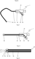
- Figure 1 shows schematically the structure of an endoscope 1 according to the invention.
- a simple flexible endoscope 1 is shown here in a highly simplified manner, which has a handpiece 10 and a flexible section 20, wherein the flexible section 20 can be inserted into a body cavity, for example.
- an illumination light guide 30, which has a proximal sleeve 40 on an illumination device designed as an LED 60 in the handpiece 10 and a distal sleeve 50 at the end of the flexible section 20.
- the light of the LED 60 is coupled into the end surface of the proximal sleeve 40 and guided via the illumination light guide 30 to the distal sleeve 50, and can then be emitted into the interior of the body via corresponding coupling optics.
- the imaging components can be, for example, C-MOS cameras that are integrated into the distal sleeve 50 and transmit the image information electrically to a monitor (also not shown).
- Fiber optic image guides that transmit the image information to a camera or directly to an eyepiece optic are also conceivable. Such image guides consist of several thousand fine individual glass fibers, only a few ⁇ m thick, which transmit the image information pixel by pixel.
- the following typical dimensions are conceivable for such light guides: length between 100 mm and 3000 mm, typically 500 to 1000 mm, light guide diameter between 0.5 mm and 5 mm, typically between 1 and 2 mm.
- Figure 2 also shows, schematically and in a highly simplified manner, an endoscope 1 which is designed as a rigid endoscope 1.
- the illumination light guide 30 is guided in a rigid shaft 25.
- the imaging or image-transmitting components, as previously described, are not shown for the sake of clarity.
- an illumination light guide 30 is shown in a partial view with a distal sleeve 50.
- the illumination light guide 30 in this case consists of an extruded cable 31, with a plastic sheath enclosing a fiber bundle 32.
- the fiber bundle termination is carried out in such a way that the jacket of the extruded cable 31 is insulated at the end, and a clear transparent sleeve previously produced in an injection molding process as distal sleeve 50 with its receiving section 52 is pushed onto the exposed fiber bundle 32 and the sleeve is fixed with clear transparent resin previously applied to this sleeve, for example in the form of a preferably fast hot-curing or UV-curing adhesive.
- the distal end surface 53 of the fiber bundle 32 is thus covered with a clear transparent plastic.
- This type of termination can also be used on the proximal sleeve 40 of the illumination light guide 30. In this case, the proximal end surface 43 can be covered with a clear transparent plastic.
- proximal and distal sleeves 40, 50 can have mechanical interfaces 44, 54 that result from the outer contour of the proximal and distal sleeves 40, 50. These can be circumferential grooves, locking lugs, notches, flanges and the like.
- these sleeves can also be designed as optical elements 51 in the form of lenses (convex or concave) or as an irregularly shaped end surface for beam shaping.
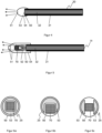
- Figure 3 shows only schematically the distal sleeve 50 with an optical element 51 in the form of a lens dome formed during the injection molding process, with which the emerging light can be bundled, for example.
- the functionality of the input and/or output sleeve or the proximal and/or distal sleeve 40, 50 can be implemented particularly cost-effectively in the design of the tool and enables an extremely cost-effective termination of the proximal or distal end surfaces 43, 53.
- the fiber bundle 32 of the illumination light guide 30 or the image guide can consist of glass fibers (GOF), quartz fibers or plastic fibers (POF), which is covered with an extruded sheath, as in Figure 3 shown, is surrounded by a hose or mesh tube fabric.
- the sheath plastic of the extruded cable 31 consists of an opaque colored plastic.
- the fiber bundle 32 itself and/or its individual fibers can have an electrically conductive coating at least partially or in sections and/or the sheath plastic can be formed at least partially or in sections from or with an electrically conductive material.
- the following table shows a material overview of plastics which are suitable for the sheath of the cable 31 as well as for the clear transparent cover of the proximal or distal end surface 43, 53 or for the proximal or distal sleeve 40, 50.
- plastic types TPE-E, TPE-V and TPE-U are particularly interesting for extrusion, as they have very good extrudability and are particularly good to very good for medical use. In terms of cost-effective production, these materials also have comparatively low material costs. Inexpensive plastics such as PVC, compounds and blends made of PP, PE, TPE-S (SEBS) sometimes have significant deficits, especially in the area of temperature resistance. They can usually not be used above 100° C. However, the temperature requirements for disposable endoscopes are significantly lower, so these materials are particularly suitable for this use due to their low material costs and problem-free processing.
- An example of a commonly used sterilization method is gassing with ethylene oxide.
- the group of inexpensive and medium-priced plastics are generally available in a wide range of elasticity and hardness levels, or can be produced by mixing several types of plastic to form a poly-blend with the desired performance. This has the advantage over "expensive" plastics, such as FEP and PVDF, that they can be used to produce lighting light guides 30 with almost identical properties but with different levels of flexibility.
- COC is also very suitable as a material for the transparent sleeves, as it has a high optical quality in terms of high transparency and low turbidity and is used in particular for syringes and pharmaceutical containers. These are also available as biocompatible variants.
- the glass fiber bundles or the plastic light guides can also be encased in a thin-walled tube or shrink tube for protection.
- Extremely thin-walled shrink tubes can be used for shrink tubes (example: PET shrink tube with a wall thickness of 6 ⁇ m).
- Thin-walled mesh tubes made of glass silk or plastic silk are also conceivable.
- the glass fibers can preferably consist of a Pb- and heavy metal-free core glass and cladding glass for medical applications, which particularly favors the RoHS and REACH requirements and medical approval.
- Such glass systems are used to manufacture Pb- and heavy metal-free fibers, which are known by the applicant under the name SCHOTT PURAVIS ® , and are described in the documents WO 2013/104748 A1 and EN 102007063463 B4 Pb- and heavy metal-free rigid fiber optic elements are described in EN 102013208838 B4 described.
- glass fibers with high NA values are particularly suitable, i.e.
- Such fibers are known, for example, under the name SCHOTT PURAVIS ® GOF85 or GOF120.
- Figure 4 shows a detail of an alternative approach of an illumination light guide 30 with distal sleeve 50, which can also be designed in the same way for the proximal sleeve 40.
- the fiber bundles are, for example, extruded beforehand, that is, the fiber bundle 32 is coated with a plastic to form a cable 31, cut to length and then either fed to an injection molding process in which the cable sections are directly overmolded with the transparent plastic and a sleeve, here a distal sleeve 50, is formed.
- the cable end may have to be grabbed at least at 2 opposite points using semicircular collets in a first step and at least partially overmolded. In a second injection molding process, it may then be provided to mold the final sleeve geometry.
- Figure 5 shows a variant of the Figure 3
- the distal sleeve 50 shown here again as an example on the illumination light guide 30, as extruded cable 31 with the fiber bundle 32 shown, here has a central area in which, for example, a camera chip 70 (C-MOS chip) can be inserted, wherein the fiber bundle 32 of the illumination light guide 30 is arranged in a ring shape, at least in sections in a ring shape or in at least two partial strands around the camera chip 70.
- the receiving area 52 of the fiber bundle 32 is conically expanded accordingly.
- Optical elements 51 can also be molded on during manufacture of the sleeve, or can be additionally applied in a subsequent bonding process.
- Figure 6a to 6c show schematically typical arrangements of the distal end surface 53 of the illumination light guide 30 in connection with a camera chip 70, wherein in these examples the distal sleeve 50 represents the end of the shaft 25 of the endoscope 1.
- Figure 6a shows an arrangement in which the camera chip 70 is substantially enclosed by the distal end surface 53.
- Figure 6b shows a substantially U-shaped distal end surface 53.
- Figure 6c shows an example of an arrangement in which the camera chip 70 is surrounded by two D-shaped distal end surfaces 53 opposite one another.
- 3- or 4-part distal end surfaces 53 are also conceivable, which enclose the camera chip 70 as circular or oval or kidney-shaped exit surfaces.
- the geometric arrangement is accordingly predetermined in the distal sleeve 50.
- Such sleeves can be manufactured particularly cost-effectively by means of injection molding.
- Figure 7 shows in the sectional view, for example, a distal sleeve 50 corresponding to the Figure 6a shown arrangement of distal end surface 53 and camera chip 70.
- the distal sleeve 50 is shown here as the end of a rigid shaft 25 of the endoscope 1, which can be designed as a stainless steel tube, for example.
- the distal end surface 53 is arranged essentially in a ring around the centrally arranged camera chip 70.
- the light emitted by this is reflected, for example, by a tissue surface 90 to be examined and captured by the camera chip 70.
- the camera chip 70 is covered for protection, whereby the cover can be designed as an optical element 51, for example as a converging lens. Multi-lens arrangements as the optical element 51 are also conceivable.
- the camera chip 70 is contacted with electrical lines 210, which are led through a feedthrough 56 in the distal sleeve 50 into the interior of the shaft 25.
- the fiber bundle 32 here made of glass fibers with a high NA (acceptance angle 2 ⁇ > 100°), is fanned out in a ring shape and fixed in an annular receiving section 52 arranged around the feedthrough 56.
- This receiving section 52 has walls that are almost parallel to one another in order to enable the fibers to be aligned as parallel as possible.
- the distal sleeve 50 has conically shaped areas adjacent to the receiving section 52 in order to make it easier to thread the fibers.
- the fiber bundle 32 is surrounded inside the shaft 25 by a protective cover 33, which can be an extruded jacket, a mesh tube or a shrink tube.
- a thin-walled PET shrink tube for example, is used as the protective cover.
- These have a wall thickness of ⁇ 10 ⁇ m.
- the distal sleeve 50 may have further mechanical interfaces 54 on its outer contour, for example in the form of collars or, as shown, a diameter jump, in order to connect the distal sleeve 50 to the shaft 25.
- various adhesive areas 55 are provided, on the one hand for fixing the fibers of the fiber bundle 32 and on the other hand for fastening the camera chip 70 or for additional sealing of the feedthrough 56 of the electrical lines 210.
- the entire distal sleeve 50 is made of a clear transparent plastic, for example PC or PMMA, and a UV-curing adhesive is used, wherein in particular in the receiving section 52 an adhesive or a casting resin is used to fix the fibers, the optical refractive index of which is essentially adapted to that of the core material of the fibers and a deviation of these refractive indices is a maximum of ⁇ 0.1, preferably a maximum of ⁇ 0.05 and wherein the refractive index of the sleeve is slightly lower than that of the adhesive.
- the camera chip 70 is mounted on the back of the distal sleeve 50 and the distal end surface 53 forms a cover. In this way, improved electrical insulation can be achieved without an additional cover element.
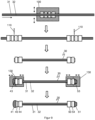
- a proximal sleeve 40 is shown on the illumination light guide 30, in which a LED 60 with LED controller unit 70 is integrated into the proximal sleeve 40.
- LED 60 and LED controller unit 70 are in a... Figure 3 separately manufactured proximal sleeve 40, wherein the end of the fiber bundle 32 is mounted or fixed in a receptacle 42 formed in the proximal sleeve 40.
- the proximal end surface 43 can be provided with a clear transparent cover, which can be designed as a condenser lens or a structure comprising the LED chip in order to enable optimal light coupling into the fiber bundle 32.
- Figure 9 shows, in an "endless" process, a previously extruded cable 31 with the fiber bundle 32 is rewound from an unwinder to a winder, and the rewinding is stopped at certain intervals and a double plastic sleeve is injected on by means of a first injection molding tool 100.
- a double sleeve is stamped around the cable 31 in a form-fitting manner without an intermediate layer, which is separated by means of separating devices 110 in a subsequent cutting process with the cable 31.
- multi-lumen cables 200 can be manufactured, as Figure 10 schematically shows. These can have fiber bundles 32, quartz fibers 220, electrical cables 210 and a fluid channel 230 for media guidance of gas (for example nitrogen), water, medication or rinsing liquids.
- the quartz fibers 220 can be used for optical data transfer or control, for example.
- Multi-lumen tubes are already known from the literature. The integration of light or energy-carrying components is particularly advantageous here, which enable high functionality in the smallest of spaces.
- the cables are specifically They can be made transparent or opaque in segments and can therefore also fulfil lighting or optical detection tasks.
- crimped sleeves as used in the EN 102004048741 B3 described.
- plastic crimp or locking sleeves can be used, which are previously manufactured using an injection molding process and are foldable with a folding hinge (here a film hinge). These sleeves are then mounted at the end of the cable section of the extruded cable in a locking manner and can then be filled or sprayed with optically transparent adhesive. UV-curing adhesives are also advantageous here.
- the sleeves can also be fixed to the cable using laser welding or ultrasonic welding.
- Another method results from the elastic properties of a cable.
- the idea is to cut an extruded cable and then lengthen the cable sheath and fill the resulting cavity with optically clear adhesive or to insert a prefabricated clear transparent plastic part or a light guide rod or fiber rod made of glass or plastic into the cavity and fix it in place.
- a fastening element can be formed by deliberately deforming the exposed cable sections.
- Thermoplastic elastomers (TPE) or elastomers such as rubber or silicone are particularly suitable as sheath materials.
- Another alternative for cost-effective termination of optical fibers can be partial heating of a cable filled with gel so that the gel hardens there and the cable can be cut and possibly reshaped or sleeves can be formed.
- the cable can also be manufactured using coextrusion and have a transparent section along the axis of the cable, over which the gel can then be partially hardened in sections using UV light. This can also be used to implement an endless process for termination.
Landscapes
- Health & Medical Sciences (AREA)
- Life Sciences & Earth Sciences (AREA)
- Physics & Mathematics (AREA)
- Surgery (AREA)
- Optics & Photonics (AREA)
- Engineering & Computer Science (AREA)
- Medical Informatics (AREA)
- Veterinary Medicine (AREA)
- Pathology (AREA)
- Nuclear Medicine, Radiotherapy & Molecular Imaging (AREA)
- Biomedical Technology (AREA)
- Heart & Thoracic Surgery (AREA)
- Biophysics (AREA)
- Molecular Biology (AREA)
- Animal Behavior & Ethology (AREA)
- General Health & Medical Sciences (AREA)
- Public Health (AREA)
- Radiology & Medical Imaging (AREA)
- General Physics & Mathematics (AREA)
- Manufacturing & Machinery (AREA)
- Mechanical Engineering (AREA)
- Astronomy & Astrophysics (AREA)
- Ophthalmology & Optometry (AREA)
- Endoscopes (AREA)
- Instruments For Viewing The Inside Of Hollow Bodies (AREA)
- Optical Couplings Of Light Guides (AREA)
- Optical Fibers, Optical Fiber Cores, And Optical Fiber Bundles (AREA)
Applications Claiming Priority (2)
| Application Number | Priority Date | Filing Date | Title |
|---|---|---|---|
| DE102018107523.5A DE102018107523A1 (de) | 2018-03-29 | 2018-03-29 | Licht- oder Bildleitkomponenten für Einweg-Endoskope |
| PCT/EP2019/057616 WO2019185645A1 (de) | 2018-03-29 | 2019-03-26 | Licht- oder bildleitkomponenten für einweg-endoskope |
Publications (2)
| Publication Number | Publication Date |
|---|---|
| EP3773127A1 EP3773127A1 (de) | 2021-02-17 |
| EP3773127B1 true EP3773127B1 (de) | 2024-09-11 |
Family
ID=65955232
Family Applications (1)
| Application Number | Title | Priority Date | Filing Date |
|---|---|---|---|
| EP19714192.2A Active EP3773127B1 (de) | 2018-03-29 | 2019-03-26 | Licht- oder bildleitkomponenten für einweg-endoskope |
Country Status (6)
| Country | Link |
|---|---|
| US (1) | US11510553B2 (enExample) |
| EP (1) | EP3773127B1 (enExample) |
| JP (3) | JP7431745B2 (enExample) |
| CN (1) | CN111936028B (enExample) |
| DE (1) | DE102018107523A1 (enExample) |
| WO (1) | WO2019185645A1 (enExample) |
Families Citing this family (21)
| Publication number | Priority date | Publication date | Assignee | Title |
|---|---|---|---|---|
| CN110325098A (zh) | 2016-11-28 | 2019-10-11 | 适内有限责任公司 | 具有可分离一次性轴的内窥镜 |
| EP3681366B1 (en) * | 2017-09-11 | 2023-12-27 | Eyelum Ltd. | Disposable miniature endoscopy system |
| DE102018107523A1 (de) | 2018-03-29 | 2019-10-02 | Schott Ag | Licht- oder Bildleitkomponenten für Einweg-Endoskope |
| EP3813629A1 (en) | 2018-06-28 | 2021-05-05 | Boston Scientific Scimed, Inc. | Encapsulated components of medical devices, and methods therefor |
| DE102019125912A1 (de) | 2019-09-26 | 2021-04-01 | Schott Ag | Lichtleiter für Diagnose-, Operations- und/oder Therapiegerät |
| DE102019131076B4 (de) * | 2019-11-18 | 2025-03-20 | Schölly Fiberoptic GmbH | Endoskop und Endoskopanordnung sowie Verfahren zur Nutzung einer Bilderfassungseinheit mit mehreren Endoskopen |
| JP7348641B2 (ja) * | 2019-12-03 | 2023-09-21 | 株式会社住田光学ガラス | 光ファイバ照明装置 |
| DE102019133042A1 (de) | 2019-12-04 | 2021-06-10 | Schott Ag | Endoskop, Einweg-Endoskopsystem und Lichtquelle für Endoskop |
| USD1018844S1 (en) | 2020-01-09 | 2024-03-19 | Adaptivendo Llc | Endoscope handle |
| DE102020106915A1 (de) * | 2020-03-13 | 2021-09-16 | Schott Ag | Endoskop und Einweg-Endoskopsystem |
| DE102020113465A1 (de) | 2020-05-19 | 2021-11-25 | Universitätsmedizin der Johannes Gutenberg-Universität Mainz, Körperschaft des öffentlichen Rechts | Vorrichtung zur Unterstützung der Ausleuchtung und der anatomischen Grenzdarstellung bei medizinischen Eingriffen |
| EP3964116A1 (en) | 2020-09-02 | 2022-03-09 | Ambu A/S | Endoscope tip part |
| USD1051380S1 (en) | 2020-11-17 | 2024-11-12 | Adaptivendo Llc | Endoscope handle |
| EP4011270A1 (en) | 2020-12-08 | 2022-06-15 | Ambu A/S | Endoscope tip part with improved optical properties |
| US20220197008A1 (en) * | 2020-12-18 | 2022-06-23 | Precision Optics Corporation, Inc. | System and method for treating ends of optical fibers for use in an endoscope |
| CN214906602U (zh) * | 2021-01-07 | 2021-11-30 | 上海视介光电科技有限公司 | 一种内窥镜照明装置 |
| DE102021109023B4 (de) | 2021-04-12 | 2024-08-14 | Karl Storz Se & Co. Kg | Endoskop, insbesondere medizinisches Einweg-Endoskop |
| USD1031035S1 (en) | 2021-04-29 | 2024-06-11 | Adaptivendo Llc | Endoscope handle |
| USD1070082S1 (en) | 2021-04-29 | 2025-04-08 | Adaptivendo Llc | Endoscope handle |
| USD1066659S1 (en) | 2021-09-24 | 2025-03-11 | Adaptivendo Llc | Endoscope handle |
| CN117045175B (zh) * | 2023-10-11 | 2024-09-10 | 福建福特科光电股份有限公司 | 一种内窥镜及其制作方法 |
Citations (1)
| Publication number | Priority date | Publication date | Assignee | Title |
|---|---|---|---|---|
| WO2015168247A1 (en) * | 2014-04-29 | 2015-11-05 | Sinofsky Edward L | Lumen-less illumination system |
Family Cites Families (83)
| Publication number | Priority date | Publication date | Assignee | Title |
|---|---|---|---|---|
| DE1596485B1 (de) | 1967-10-19 | 1970-07-02 | Jenaer Glaswerk Schott & Gen | Verfahren zur Herstellung von waermebestaendigen,flexiblen Lichtleitern aus einer Vielzahl von optisch isolierten,von einem Schutzschlauch umhuellten Lichtleitfasern |
| US3581738A (en) | 1968-11-12 | 1971-06-01 | Welch Allyn Inc | Disposable illuminating endoscope and method of manufacture |
| JPS61143120A (ja) | 1984-12-17 | 1986-06-30 | Hitachi Ltd | 真空パツキング治具 |
| JPH055530Y2 (enExample) * | 1985-02-26 | 1993-02-15 | ||
| AU583337B2 (en) | 1985-01-14 | 1989-04-27 | Sumitomo Electric Industries, Ltd. | Fiberscope |
| CA1291352C (en) | 1986-07-29 | 1991-10-29 | Atsushi Utsumi | Optical fiber conductor and image scope using same |
| JPS63151918A (ja) * | 1986-12-16 | 1988-06-24 | Olympus Optical Co Ltd | 内視鏡 |
| JPS63277030A (ja) | 1987-05-09 | 1988-11-15 | Mitsubishi Cable Ind Ltd | カテ−テル形ファイバスコ−プ |
| WO1989012479A1 (en) * | 1988-06-16 | 1989-12-28 | Optimed Technologies, Inc. | Angioplasty catheter with integral fiber optic |
| US4964710B1 (en) | 1989-07-27 | 1994-08-16 | Monadnock Optics Inc | Disposable rigid endoscope |
| US5436655A (en) | 1991-08-09 | 1995-07-25 | Olympus Optical Co., Ltd. | Endoscope apparatus for three dimensional measurement for scanning spot light to execute three dimensional measurement |
| US5704899A (en) | 1995-10-10 | 1998-01-06 | Conceptus, Inc. | Protective sheath for a fiberoptic image guide within an articulated endoscope |
| US5761356A (en) | 1996-08-19 | 1998-06-02 | Cogent Light Technologies, Inc. | Apparatus and method for coupling high intensity light into low temperature optical fiber |
| JPH10258022A (ja) * | 1997-01-20 | 1998-09-29 | Suzuki Motor Corp | ハイブリッドオペレーションシステム |
| US6249348B1 (en) | 1998-11-23 | 2001-06-19 | Lj Laboratories, L.L.C. | Integrated spectrometer assembly and methods |
| JP2000079089A (ja) * | 1998-09-07 | 2000-03-21 | Olympus Optical Co Ltd | 内視鏡用サーモグラフィー装置 |
| ATE223679T1 (de) | 1998-12-07 | 2002-09-15 | Lea Medizintechnik Gmbh | Detektionssonde für die tiefenauflösende licht- spektroskopie und spektrometrie |
| US6398721B1 (en) | 1999-02-19 | 2002-06-04 | Olympus Optical Co., Ltd. | Surgical microscope apparatus |
| JP2003290135A (ja) | 2002-04-05 | 2003-10-14 | Fibertech Co Ltd | 近観察用ファイバースコープ及びその製造方法 |
| US7229201B2 (en) | 2003-03-26 | 2007-06-12 | Optim Inc. | Compact, high-efficiency, high-power solid state light source using a single solid state light-emitting device |
| US20050197623A1 (en) | 2004-02-17 | 2005-09-08 | Leeflang Stephen A. | Variable steerable catheters and methods for using them |
| US7976462B2 (en) | 2004-04-06 | 2011-07-12 | Integrated Endoscopy, Inc. | Endoscope designs and methods of manufacture |
| US7559925B2 (en) | 2006-09-15 | 2009-07-14 | Acclarent Inc. | Methods and devices for facilitating visualization in a surgical environment |
| US8480566B2 (en) | 2004-09-24 | 2013-07-09 | Vivid Medical, Inc. | Solid state illumination for endoscopy |
| DE102004048741B8 (de) | 2004-10-05 | 2007-02-01 | Schott Ag | Verfahren zur Herstellung eines Lichtleitfaserabschlusses |
| US7433115B2 (en) | 2004-12-15 | 2008-10-07 | Nichia Corporation | Light emitting device |
| WO2006076759A1 (en) | 2005-01-21 | 2006-07-27 | Optiscan Pty Ltd | Fibre bundle for contact endomicroscopy |
| JP2006343402A (ja) | 2005-06-07 | 2006-12-21 | Olympus Medical Systems Corp | 光ファイバー束及びその製造方法 |
| JP5124978B2 (ja) | 2005-06-13 | 2013-01-23 | 日亜化学工業株式会社 | 発光装置 |
| US7955255B2 (en) | 2006-04-20 | 2011-06-07 | Boston Scientific Scimed, Inc. | Imaging assembly with transparent distal cap |
| US7474820B2 (en) * | 2006-04-27 | 2009-01-06 | Invuity, Inc. | Micro-optic adapters and tips for surgical illumination fibers |
| DE102006040214B4 (de) | 2006-08-28 | 2008-07-10 | Fresenius Medical Care Deutschland Gmbh | Verfahren zum Zusammenfassen von Hohlfasern zu einem Bündel und mit diesem Verfahren hergestelltes Hohlfaserbündel |
| DE102006053487B4 (de) | 2006-11-14 | 2013-12-19 | Storz Endoskop Produktions Gmbh | Endoskopisches System mit fasergepumpter Fluoreszenzbeleuchtung |
| TWI361293B (en) | 2006-12-15 | 2012-04-01 | Chun Chu Yang | The coaxial light-guide system consisting of coaxial light-guide fiber basing its refractive index profiles on radii and with its coaxial both semiconductor light sources and semiconductor detectors |
| DE102007026234A1 (de) | 2007-05-31 | 2008-12-04 | Karl Storz Gmbh & Co. Kg | Videoendoskop |
| JP2009018081A (ja) * | 2007-07-13 | 2009-01-29 | Olympus Medical Systems Corp | 内視鏡、内視鏡本体、および、内視鏡用アダプタ |
| DE102007063463B4 (de) | 2007-12-20 | 2010-06-10 | Schott Ag | Kernglas im Alkali-Zink-Silikat-Glassystem für einen faseroptischen Lichtleiter und die Verwendung des Kernglases in einem Lichtleiter |
| JP2009268635A (ja) * | 2008-05-02 | 2009-11-19 | Hoya Corp | 内視鏡ライトガイド可撓管およびその外皮層の製造方法 |
| JP5216429B2 (ja) | 2008-06-13 | 2013-06-19 | 富士フイルム株式会社 | 光源装置および内視鏡装置 |
| DE102008044938B4 (de) * | 2008-08-29 | 2013-10-10 | Schott Ag | Verfahren zur Terminierung von lichtleitenden Faserbündeln sowie Hülse mit einem Faserbündel |
| DE102009004159B4 (de) | 2009-01-09 | 2014-02-20 | Schott Ag | Verfahren zur Herstellung einer Multi-Core-Preform |
| ES2667486T3 (es) | 2010-05-13 | 2018-05-11 | Doheny Eye Institute | Sistema autónomo con cánula de infusión iluminada |
| JP2012016545A (ja) | 2010-07-09 | 2012-01-26 | Fujifilm Corp | 内視鏡装置 |
| JP5701544B2 (ja) | 2010-09-02 | 2015-04-15 | オリンパス株式会社 | 樹脂成形品とその製造方法と樹脂成形品用成形型 |
| WO2012050116A1 (ja) * | 2010-10-12 | 2012-04-19 | オリンパスメディカルシステムズ株式会社 | 内視鏡 |
| JP5864870B2 (ja) | 2011-03-01 | 2016-02-17 | オリンパス株式会社 | 光源システム |
| KR101238765B1 (ko) * | 2011-09-22 | 2013-03-04 | 주식회사 옵티메드 | 일회용 내시경 |
| DE102011114575A1 (de) | 2011-09-30 | 2013-04-04 | Schott Ag | Ummantelter Lichtleiter und Verfahren zu dessen Herstellung |
| DE102011119972B4 (de) | 2011-12-02 | 2015-10-01 | Schott Ag | Verfahren zum Koppeln eines Glasfaserbündels mit einem optischen Konversionselement sowie Baugruppe mit einem optischen Konversionselement und einem Glasfaserbündel |
| DE102011089769A1 (de) | 2011-12-23 | 2013-06-27 | Osram Gmbh | Endoskop |
| DE102012100233B4 (de) | 2012-01-12 | 2014-05-15 | Schott Ag | Hochtransmittive Gläser mit hoher Solarisationsbeständigkeit, ihre Verwendung und Verfahren zu ihrer Herstellung |
| US20140107630A1 (en) | 2012-09-27 | 2014-04-17 | Trimedyne, Inc. | Side firing optical fiber device for consistent, rapid vaporization of tissue and extended longevity |
| EP3827733B1 (en) * | 2013-02-01 | 2022-08-03 | DEKA Products Limited Partnership | Endoscope with pannable camera |
| CA3135151A1 (en) | 2013-04-08 | 2014-10-16 | Boston Scientific Scimed, Inc. | Fluid management system |
| DE102013208838B4 (de) | 2013-05-14 | 2015-03-05 | Schott Ag | Beleuchtungseinrichtung mit erweitertem Nutzspektrum und deren Verwendung |
| JP6442141B2 (ja) | 2014-01-23 | 2018-12-19 | オリンパス株式会社 | 光源モジュールと光源モジュールを有する内視鏡用光源システム |
| JP2017506947A (ja) | 2014-02-06 | 2017-03-16 | デンツプライ シロナ インコーポレーテッド | 歯根およびその歯内空洞空間の検査 |
| JP6314008B2 (ja) | 2014-03-20 | 2018-04-18 | オリンパス株式会社 | 内視鏡システム |
| DE102014208756A1 (de) * | 2014-05-09 | 2015-11-12 | Schott Ag | Lichtleiter mit angeformtem optischen Element |
| JP2015228887A (ja) * | 2014-06-03 | 2015-12-21 | 株式会社渋谷光学 | ファイバースコープ、歯科用プローブ |
| EP3171753B1 (en) * | 2014-07-24 | 2025-06-25 | Zsquare Ltd | Multicore fiber endoscopes |
| JP6423278B2 (ja) | 2015-02-09 | 2018-11-14 | 富士フイルム株式会社 | 内視鏡の湾曲部及び内視鏡 |
| JPWO2016185537A1 (ja) | 2015-05-18 | 2018-03-01 | オリンパス株式会社 | 内視鏡、および光伝送モジュール |
| WO2017064990A1 (ja) | 2015-10-14 | 2017-04-20 | オリンパス株式会社 | 内視鏡用光源装置及び内視鏡システム |
| DE102015015041B4 (de) | 2015-11-24 | 2025-03-20 | Schölly Fiberoptic GmbH | Endoskop mit einem wiederverwendbaren Teil und einem Einwegteil |
| JP6006894B1 (ja) | 2016-02-02 | 2016-10-12 | 株式会社住田光学ガラス | イメージガイドファイバ |
| JP6901830B2 (ja) * | 2016-04-25 | 2021-07-14 | パナソニックi−PROセンシングソリューションズ株式会社 | 内視鏡 |
| US10827911B2 (en) | 2016-06-03 | 2020-11-10 | Trustees Of Boston University | Optical imaging system employing vortex fiber for multiple-mode illumination |
| DE102016216443A1 (de) * | 2016-08-31 | 2018-03-01 | Schott Ag | Beleuchtungssystem mit heterogener Faseranordnung |
| JP7086860B2 (ja) | 2016-12-27 | 2022-06-20 | 三菱電線工業株式会社 | 光ファイバ心線 |
| DE102017108698A1 (de) | 2017-04-24 | 2018-10-25 | Osram Gmbh | Optoelektronisches Bauelement |
| DE102017115739A1 (de) | 2017-07-13 | 2019-01-17 | Karl Storz Se & Co. Kg | Bildgebendes medizinisches Instrument wie ein Endoskop, ein Exoskop oder ein Mikroskop |
| US11445890B2 (en) | 2017-08-17 | 2022-09-20 | David M Schreck | Modular endoscope |
| WO2019036048A2 (en) | 2017-08-17 | 2019-02-21 | Stryker European Holdings I, Llc | SIDE ACCESS BRIDGES, SADDLES AND LIGHTS COMPRISING BAR LIGHTING |
| WO2019049376A1 (ja) | 2017-09-11 | 2019-03-14 | オリンパス株式会社 | 内視鏡システム |
| US11454756B2 (en) | 2017-09-22 | 2022-09-27 | Toray Industries, Inc. | Plastic optical fiber for medical device lighting and medical device lighting using same |
| DE102017122756A1 (de) | 2017-09-29 | 2019-04-04 | Schott Ag | Beleuchtungssystem mit einem Lichtleiter mit Diffusor-Element |
| DE102018107523A1 (de) | 2018-03-29 | 2019-10-02 | Schott Ag | Licht- oder Bildleitkomponenten für Einweg-Endoskope |
| CA3278609A1 (en) | 2018-06-08 | 2025-10-30 | Psip2 Llc | Endocope with disposable camera shaft and reusable handle |
| US10393957B1 (en) | 2018-07-18 | 2019-08-27 | Valco North America, Inc. | Glued optical fiber bundle |
| DE102019125912A1 (de) | 2019-09-26 | 2021-04-01 | Schott Ag | Lichtleiter für Diagnose-, Operations- und/oder Therapiegerät |
| US11215752B1 (en) | 2019-12-13 | 2022-01-04 | Apple Inc. | Electronic devices with image transport layers |
| DE102020106915A1 (de) | 2020-03-13 | 2021-09-16 | Schott Ag | Endoskop und Einweg-Endoskopsystem |
-
2018
- 2018-03-29 DE DE102018107523.5A patent/DE102018107523A1/de active Pending
-
2019
- 2019-03-26 WO PCT/EP2019/057616 patent/WO2019185645A1/de not_active Ceased
- 2019-03-26 CN CN201980023184.4A patent/CN111936028B/zh active Active
- 2019-03-26 JP JP2020552310A patent/JP7431745B2/ja active Active
- 2019-03-26 EP EP19714192.2A patent/EP3773127B1/de active Active
-
2020
- 2020-09-29 US US17/037,402 patent/US11510553B2/en active Active
-
2023
- 2023-11-01 JP JP2023187607A patent/JP2024010148A/ja active Pending
-
2025
- 2025-06-16 JP JP2025100228A patent/JP2025134817A/ja active Pending
Patent Citations (1)
| Publication number | Priority date | Publication date | Assignee | Title |
|---|---|---|---|---|
| WO2015168247A1 (en) * | 2014-04-29 | 2015-11-05 | Sinofsky Edward L | Lumen-less illumination system |
Also Published As
| Publication number | Publication date |
|---|---|
| CN111936028A (zh) | 2020-11-13 |
| JP2025134817A (ja) | 2025-09-17 |
| WO2019185645A1 (de) | 2019-10-03 |
| EP3773127A1 (de) | 2021-02-17 |
| DE102018107523A1 (de) | 2019-10-02 |
| JP2024010148A (ja) | 2024-01-23 |
| JP2021517049A (ja) | 2021-07-15 |
| JP7431745B2 (ja) | 2024-02-15 |
| US20210022588A1 (en) | 2021-01-28 |
| CN111936028B (zh) | 2024-12-27 |
| US11510553B2 (en) | 2022-11-29 |
Similar Documents
| Publication | Publication Date | Title |
|---|---|---|
| EP3773127B1 (de) | Licht- oder bildleitkomponenten für einweg-endoskope | |
| EP3878346B1 (de) | Endoskop und einweg-endoskopsystem | |
| US12226075B2 (en) | Endoscope with variable profile tip | |
| US7708688B2 (en) | Polymer endoscopic shaft | |
| EP3831273B1 (de) | Endoskop, einweg-endoskopsystem und lichtquelle für endoskop | |
| DE102015015041B4 (de) | Endoskop mit einem wiederverwendbaren Teil und einem Einwegteil | |
| EP3797675A1 (de) | Lichtleiter für diagnose-, operations- und/oder therapiegerät | |
| DE112013006864T5 (de) | Führungsdraht | |
| EP3289960B1 (de) | Beleuchtungssystem mit heterogener faseranordnung | |
| DE102015000773B4 (de) | Endoskop und Verfahren zur Herstellung eines Endoskops | |
| DE9319453U1 (de) | Vorrichtung zur Inkorporation elektromagnetischer Wellen | |
| DE10061746A1 (de) | Endoskopische Leuchte |
Legal Events
| Date | Code | Title | Description |
|---|---|---|---|
| STAA | Information on the status of an ep patent application or granted ep patent |
Free format text: STATUS: UNKNOWN |
|
| STAA | Information on the status of an ep patent application or granted ep patent |
Free format text: STATUS: THE INTERNATIONAL PUBLICATION HAS BEEN MADE |
|
| PUAI | Public reference made under article 153(3) epc to a published international application that has entered the european phase |
Free format text: ORIGINAL CODE: 0009012 |
|
| STAA | Information on the status of an ep patent application or granted ep patent |
Free format text: STATUS: REQUEST FOR EXAMINATION WAS MADE |
|
| 17P | Request for examination filed |
Effective date: 20201014 |
|
| AK | Designated contracting states |
Kind code of ref document: A1 Designated state(s): AL AT BE BG CH CY CZ DE DK EE ES FI FR GB GR HR HU IE IS IT LI LT LU LV MC MK MT NL NO PL PT RO RS SE SI SK SM TR |
|
| AX | Request for extension of the european patent |
Extension state: BA ME |
|
| DAV | Request for validation of the european patent (deleted) | ||
| DAX | Request for extension of the european patent (deleted) | ||
| RAP3 | Party data changed (applicant data changed or rights of an application transferred) |
Owner name: SCHOTT AG |
|
| STAA | Information on the status of an ep patent application or granted ep patent |
Free format text: STATUS: EXAMINATION IS IN PROGRESS |
|
| 17Q | First examination report despatched |
Effective date: 20230104 |
|
| P01 | Opt-out of the competence of the unified patent court (upc) registered |
Effective date: 20230516 |
|
| GRAP | Despatch of communication of intention to grant a patent |
Free format text: ORIGINAL CODE: EPIDOSNIGR1 |
|
| STAA | Information on the status of an ep patent application or granted ep patent |
Free format text: STATUS: GRANT OF PATENT IS INTENDED |
|
| RIC1 | Information provided on ipc code assigned before grant |
Ipc: G02B 6/36 20060101ALN20240429BHEP Ipc: G02B 6/32 20060101ALN20240429BHEP Ipc: G02B 6/04 20060101ALN20240429BHEP Ipc: G02B 6/26 20060101ALN20240429BHEP Ipc: G02B 23/26 20060101ALI20240429BHEP Ipc: G02B 23/24 20060101ALI20240429BHEP Ipc: F21V 8/00 20060101ALI20240429BHEP Ipc: A61B 1/07 20060101ALI20240429BHEP Ipc: A61B 1/00 20060101AFI20240429BHEP |
|
| INTG | Intention to grant announced |
Effective date: 20240524 |
|
| RIC1 | Information provided on ipc code assigned before grant |
Ipc: G02B 6/36 20060101ALN20240513BHEP Ipc: G02B 6/32 20060101ALN20240513BHEP Ipc: G02B 6/04 20060101ALN20240513BHEP Ipc: G02B 6/26 20060101ALN20240513BHEP Ipc: G02B 23/26 20060101ALI20240513BHEP Ipc: G02B 23/24 20060101ALI20240513BHEP Ipc: F21V 8/00 20060101ALI20240513BHEP Ipc: A61B 1/07 20060101ALI20240513BHEP Ipc: A61B 1/00 20060101AFI20240513BHEP |
|
| GRAS | Grant fee paid |
Free format text: ORIGINAL CODE: EPIDOSNIGR3 |
|
| GRAA | (expected) grant |
Free format text: ORIGINAL CODE: 0009210 |
|
| STAA | Information on the status of an ep patent application or granted ep patent |
Free format text: STATUS: THE PATENT HAS BEEN GRANTED |
|
| AK | Designated contracting states |
Kind code of ref document: B1 Designated state(s): AL AT BE BG CH CY CZ DE DK EE ES FI FR GB GR HR HU IE IS IT LI LT LU LV MC MK MT NL NO PL PT RO RS SE SI SK SM TR |
|
| REG | Reference to a national code |
Ref country code: GB Ref legal event code: FG4D Free format text: NOT ENGLISH |
|
| REG | Reference to a national code |
Ref country code: CH Ref legal event code: EP |
|
| REG | Reference to a national code |
Ref country code: DE Ref legal event code: R096 Ref document number: 502019012101 Country of ref document: DE |
|
| REG | Reference to a national code |
Ref country code: IE Ref legal event code: FG4D Free format text: LANGUAGE OF EP DOCUMENT: GERMAN |
|
| REG | Reference to a national code |
Ref country code: LT Ref legal event code: MG9D |
|
| PG25 | Lapsed in a contracting state [announced via postgrant information from national office to epo] |
Ref country code: NO Free format text: LAPSE BECAUSE OF FAILURE TO SUBMIT A TRANSLATION OF THE DESCRIPTION OR TO PAY THE FEE WITHIN THE PRESCRIBED TIME-LIMIT Effective date: 20241211 |
|
| REG | Reference to a national code |
Ref country code: NL Ref legal event code: MP Effective date: 20240911 |
|
| PG25 | Lapsed in a contracting state [announced via postgrant information from national office to epo] |
Ref country code: GR Free format text: LAPSE BECAUSE OF FAILURE TO SUBMIT A TRANSLATION OF THE DESCRIPTION OR TO PAY THE FEE WITHIN THE PRESCRIBED TIME-LIMIT Effective date: 20241212 Ref country code: FI Free format text: LAPSE BECAUSE OF FAILURE TO SUBMIT A TRANSLATION OF THE DESCRIPTION OR TO PAY THE FEE WITHIN THE PRESCRIBED TIME-LIMIT Effective date: 20240911 |
|
| PG25 | Lapsed in a contracting state [announced via postgrant information from national office to epo] |
Ref country code: BG Free format text: LAPSE BECAUSE OF FAILURE TO SUBMIT A TRANSLATION OF THE DESCRIPTION OR TO PAY THE FEE WITHIN THE PRESCRIBED TIME-LIMIT Effective date: 20240911 |
|
| PG25 | Lapsed in a contracting state [announced via postgrant information from national office to epo] |
Ref country code: LV Free format text: LAPSE BECAUSE OF FAILURE TO SUBMIT A TRANSLATION OF THE DESCRIPTION OR TO PAY THE FEE WITHIN THE PRESCRIBED TIME-LIMIT Effective date: 20240911 |
|
| PG25 | Lapsed in a contracting state [announced via postgrant information from national office to epo] |
Ref country code: HR Free format text: LAPSE BECAUSE OF FAILURE TO SUBMIT A TRANSLATION OF THE DESCRIPTION OR TO PAY THE FEE WITHIN THE PRESCRIBED TIME-LIMIT Effective date: 20240911 |
|
| PG25 | Lapsed in a contracting state [announced via postgrant information from national office to epo] |
Ref country code: ES Free format text: LAPSE BECAUSE OF FAILURE TO SUBMIT A TRANSLATION OF THE DESCRIPTION OR TO PAY THE FEE WITHIN THE PRESCRIBED TIME-LIMIT Effective date: 20240911 Ref country code: RS Free format text: LAPSE BECAUSE OF FAILURE TO SUBMIT A TRANSLATION OF THE DESCRIPTION OR TO PAY THE FEE WITHIN THE PRESCRIBED TIME-LIMIT Effective date: 20241211 |
|
| PG25 | Lapsed in a contracting state [announced via postgrant information from national office to epo] |
Ref country code: RS Free format text: LAPSE BECAUSE OF FAILURE TO SUBMIT A TRANSLATION OF THE DESCRIPTION OR TO PAY THE FEE WITHIN THE PRESCRIBED TIME-LIMIT Effective date: 20241211 Ref country code: NO Free format text: LAPSE BECAUSE OF FAILURE TO SUBMIT A TRANSLATION OF THE DESCRIPTION OR TO PAY THE FEE WITHIN THE PRESCRIBED TIME-LIMIT Effective date: 20241211 Ref country code: LV Free format text: LAPSE BECAUSE OF FAILURE TO SUBMIT A TRANSLATION OF THE DESCRIPTION OR TO PAY THE FEE WITHIN THE PRESCRIBED TIME-LIMIT Effective date: 20240911 Ref country code: HR Free format text: LAPSE BECAUSE OF FAILURE TO SUBMIT A TRANSLATION OF THE DESCRIPTION OR TO PAY THE FEE WITHIN THE PRESCRIBED TIME-LIMIT Effective date: 20240911 Ref country code: GR Free format text: LAPSE BECAUSE OF FAILURE TO SUBMIT A TRANSLATION OF THE DESCRIPTION OR TO PAY THE FEE WITHIN THE PRESCRIBED TIME-LIMIT Effective date: 20241212 Ref country code: FI Free format text: LAPSE BECAUSE OF FAILURE TO SUBMIT A TRANSLATION OF THE DESCRIPTION OR TO PAY THE FEE WITHIN THE PRESCRIBED TIME-LIMIT Effective date: 20240911 Ref country code: ES Free format text: LAPSE BECAUSE OF FAILURE TO SUBMIT A TRANSLATION OF THE DESCRIPTION OR TO PAY THE FEE WITHIN THE PRESCRIBED TIME-LIMIT Effective date: 20240911 Ref country code: BG Free format text: LAPSE BECAUSE OF FAILURE TO SUBMIT A TRANSLATION OF THE DESCRIPTION OR TO PAY THE FEE WITHIN THE PRESCRIBED TIME-LIMIT Effective date: 20240911 |
|
| PG25 | Lapsed in a contracting state [announced via postgrant information from national office to epo] |
Ref country code: NL Free format text: LAPSE BECAUSE OF FAILURE TO SUBMIT A TRANSLATION OF THE DESCRIPTION OR TO PAY THE FEE WITHIN THE PRESCRIBED TIME-LIMIT Effective date: 20240911 |
|
| PG25 | Lapsed in a contracting state [announced via postgrant information from national office to epo] |
Ref country code: PT Free format text: LAPSE BECAUSE OF FAILURE TO SUBMIT A TRANSLATION OF THE DESCRIPTION OR TO PAY THE FEE WITHIN THE PRESCRIBED TIME-LIMIT Effective date: 20250113 Ref country code: IS Free format text: LAPSE BECAUSE OF FAILURE TO SUBMIT A TRANSLATION OF THE DESCRIPTION OR TO PAY THE FEE WITHIN THE PRESCRIBED TIME-LIMIT Effective date: 20250111 |
|
| PGFP | Annual fee paid to national office [announced via postgrant information from national office to epo] |
Ref country code: DE Payment date: 20250319 Year of fee payment: 7 |
|
| PG25 | Lapsed in a contracting state [announced via postgrant information from national office to epo] |
Ref country code: RO Free format text: LAPSE BECAUSE OF FAILURE TO SUBMIT A TRANSLATION OF THE DESCRIPTION OR TO PAY THE FEE WITHIN THE PRESCRIBED TIME-LIMIT Effective date: 20240911 Ref country code: SM Free format text: LAPSE BECAUSE OF FAILURE TO SUBMIT A TRANSLATION OF THE DESCRIPTION OR TO PAY THE FEE WITHIN THE PRESCRIBED TIME-LIMIT Effective date: 20240911 |
|
| PG25 | Lapsed in a contracting state [announced via postgrant information from national office to epo] |
Ref country code: EE Free format text: LAPSE BECAUSE OF FAILURE TO SUBMIT A TRANSLATION OF THE DESCRIPTION OR TO PAY THE FEE WITHIN THE PRESCRIBED TIME-LIMIT Effective date: 20240911 |
|
| PG25 | Lapsed in a contracting state [announced via postgrant information from national office to epo] |
Ref country code: CZ Free format text: LAPSE BECAUSE OF FAILURE TO SUBMIT A TRANSLATION OF THE DESCRIPTION OR TO PAY THE FEE WITHIN THE PRESCRIBED TIME-LIMIT Effective date: 20240911 Ref country code: PL Free format text: LAPSE BECAUSE OF FAILURE TO SUBMIT A TRANSLATION OF THE DESCRIPTION OR TO PAY THE FEE WITHIN THE PRESCRIBED TIME-LIMIT Effective date: 20240911 |
|
| PGFP | Annual fee paid to national office [announced via postgrant information from national office to epo] |
Ref country code: FR Payment date: 20250326 Year of fee payment: 7 |
|
| PG25 | Lapsed in a contracting state [announced via postgrant information from national office to epo] |
Ref country code: IT Free format text: LAPSE BECAUSE OF FAILURE TO SUBMIT A TRANSLATION OF THE DESCRIPTION OR TO PAY THE FEE WITHIN THE PRESCRIBED TIME-LIMIT Effective date: 20240911 Ref country code: SK Free format text: LAPSE BECAUSE OF FAILURE TO SUBMIT A TRANSLATION OF THE DESCRIPTION OR TO PAY THE FEE WITHIN THE PRESCRIBED TIME-LIMIT Effective date: 20240911 |
|
| PGFP | Annual fee paid to national office [announced via postgrant information from national office to epo] |
Ref country code: GB Payment date: 20250324 Year of fee payment: 7 |
|
| REG | Reference to a national code |
Ref country code: DE Ref legal event code: R097 Ref document number: 502019012101 Country of ref document: DE |
|
| PG25 | Lapsed in a contracting state [announced via postgrant information from national office to epo] |
Ref country code: DK Free format text: LAPSE BECAUSE OF FAILURE TO SUBMIT A TRANSLATION OF THE DESCRIPTION OR TO PAY THE FEE WITHIN THE PRESCRIBED TIME-LIMIT Effective date: 20240911 |
|
| PLBE | No opposition filed within time limit |
Free format text: ORIGINAL CODE: 0009261 |
|
| STAA | Information on the status of an ep patent application or granted ep patent |
Free format text: STATUS: NO OPPOSITION FILED WITHIN TIME LIMIT |
|
| 26N | No opposition filed |
Effective date: 20250612 |
|
| PG25 | Lapsed in a contracting state [announced via postgrant information from national office to epo] |
Ref country code: SE Free format text: LAPSE BECAUSE OF FAILURE TO SUBMIT A TRANSLATION OF THE DESCRIPTION OR TO PAY THE FEE WITHIN THE PRESCRIBED TIME-LIMIT Effective date: 20240911 |
|
| PG25 | Lapsed in a contracting state [announced via postgrant information from national office to epo] |
Ref country code: MC Free format text: LAPSE BECAUSE OF FAILURE TO SUBMIT A TRANSLATION OF THE DESCRIPTION OR TO PAY THE FEE WITHIN THE PRESCRIBED TIME-LIMIT Effective date: 20240911 |
|
| REG | Reference to a national code |
Ref country code: CH Ref legal event code: H13 Free format text: ST27 STATUS EVENT CODE: U-0-0-H10-H13 (AS PROVIDED BY THE NATIONAL OFFICE) Effective date: 20251024 |
|
| PG25 | Lapsed in a contracting state [announced via postgrant information from national office to epo] |
Ref country code: LU Free format text: LAPSE BECAUSE OF NON-PAYMENT OF DUE FEES Effective date: 20250326 |