EP3770592B1 - Gassensor und herstellungsverfahren dafür - Google Patents
Gassensor und herstellungsverfahren dafür Download PDFInfo
- Publication number
- EP3770592B1 EP3770592B1 EP19770302.8A EP19770302A EP3770592B1 EP 3770592 B1 EP3770592 B1 EP 3770592B1 EP 19770302 A EP19770302 A EP 19770302A EP 3770592 B1 EP3770592 B1 EP 3770592B1
- Authority
- EP
- European Patent Office
- Prior art keywords
- sensor element
- electrode
- green sheet
- sectional area
- laminated body
- Prior art date
- Legal status (The legal status is an assumption and is not a legal conclusion. Google has not performed a legal analysis and makes no representation as to the accuracy of the status listed.)
- Active
Links
Images





Classifications
-
- G—PHYSICS
- G01—MEASURING; TESTING
- G01N—INVESTIGATING OR ANALYSING MATERIALS BY DETERMINING THEIR CHEMICAL OR PHYSICAL PROPERTIES
- G01N27/00—Investigating or analysing materials by the use of electric, electrochemical, or magnetic means
- G01N27/02—Investigating or analysing materials by the use of electric, electrochemical, or magnetic means by investigating impedance
- G01N27/04—Investigating or analysing materials by the use of electric, electrochemical, or magnetic means by investigating impedance by investigating resistance
- G01N27/12—Investigating or analysing materials by the use of electric, electrochemical, or magnetic means by investigating impedance by investigating resistance of a solid body in dependence upon absorption of a fluid; of a solid body in dependence upon reaction with a fluid, for detecting components in the fluid
- G01N27/125—Composition of the body, e.g. the composition of its sensitive layer
-
- G—PHYSICS
- G01—MEASURING; TESTING
- G01N—INVESTIGATING OR ANALYSING MATERIALS BY DETERMINING THEIR CHEMICAL OR PHYSICAL PROPERTIES
- G01N27/00—Investigating or analysing materials by the use of electric, electrochemical, or magnetic means
- G01N27/02—Investigating or analysing materials by the use of electric, electrochemical, or magnetic means by investigating impedance
- G01N27/04—Investigating or analysing materials by the use of electric, electrochemical, or magnetic means by investigating impedance by investigating resistance
- G01N27/12—Investigating or analysing materials by the use of electric, electrochemical, or magnetic means by investigating impedance by investigating resistance of a solid body in dependence upon absorption of a fluid; of a solid body in dependence upon reaction with a fluid, for detecting components in the fluid
-
- B—PERFORMING OPERATIONS; TRANSPORTING
- B28—WORKING CEMENT, CLAY, OR STONE
- B28B—SHAPING CLAY OR OTHER CERAMIC COMPOSITIONS; SHAPING SLAG; SHAPING MIXTURES CONTAINING CEMENTITIOUS MATERIAL, e.g. PLASTER
- B28B1/00—Producing shaped prefabricated articles from the material
- B28B1/30—Producing shaped prefabricated articles from the material by applying the material on to a core or other moulding surface to form a layer thereon
-
- B—PERFORMING OPERATIONS; TRANSPORTING
- B28—WORKING CEMENT, CLAY, OR STONE
- B28B—SHAPING CLAY OR OTHER CERAMIC COMPOSITIONS; SHAPING SLAG; SHAPING MIXTURES CONTAINING CEMENTITIOUS MATERIAL, e.g. PLASTER
- B28B1/00—Producing shaped prefabricated articles from the material
- B28B1/48—Producing shaped prefabricated articles from the material by removing material from solid section preforms for forming hollow articles, e.g. by punching or boring
-
- G—PHYSICS
- G01—MEASURING; TESTING
- G01N—INVESTIGATING OR ANALYSING MATERIALS BY DETERMINING THEIR CHEMICAL OR PHYSICAL PROPERTIES
- G01N27/00—Investigating or analysing materials by the use of electric, electrochemical, or magnetic means
- G01N27/26—Investigating or analysing materials by the use of electric, electrochemical, or magnetic means by investigating electrochemical variables; by using electrolysis or electrophoresis
- G01N27/403—Cells and electrode assemblies
- G01N27/406—Cells and probes with solid electrolytes
- G01N27/4067—Means for heating or controlling the temperature of the solid electrolyte
-
- G—PHYSICS
- G01—MEASURING; TESTING
- G01N—INVESTIGATING OR ANALYSING MATERIALS BY DETERMINING THEIR CHEMICAL OR PHYSICAL PROPERTIES
- G01N33/00—Investigating or analysing materials by specific methods not covered by groups G01N1/00 - G01N31/00
- G01N33/0004—Gaseous mixtures, e.g. polluted air
- G01N33/0009—General constructional details of gas analysers, e.g. portable test equipment
- G01N33/0027—General constructional details of gas analysers, e.g. portable test equipment concerning the detector
- G01N33/0036—General constructional details of gas analysers, e.g. portable test equipment concerning the detector specially adapted to detect a particular component
Definitions
- the present invention relates to a hot spot-type oxygen sensor, which detects oxygen concentration within a measuring atmosphere, and two alternative manufacturing methods therefor.
- An oxygen sensor having an oxygen concentration detecting element made of various materials is well-known.
- the oxygen sensor using composite ceramics made by mixing LnBa 2 Cu 3 O 7- ⁇ and Ln 2 BaCuO 5 (where Ln denotes rare earth element) is known as the material composition of the oxygen sensor using a ceramic sintered body (see Patent Document 1).
- the oxygen sensor using a ceramic sintered body detects oxygen concentration utilizing a hot-spot phenomenon that a part of the linear member (sensor element) is red-heated when a voltage is applied.
- a hot spot-type oxygen sensor is characterized in that O 2- ions taken into the crystal structure of an oxygen sensor element travel to the positive electrode.
- a hot spot generating at this time moves to the negative electrode in which the number of O 2- ions have decreased.
- Patent Document 2 a narrow part formed in the sensor element made of a linear body etc. is used as a hot spot, and thus the hot spot is generated at a specific position of the sensor element.
- the central part of the element is formed to be a narrow part, which thus has a smaller cross-sectional area and a larger resistance than the other portions, resulting in generation of a hot spot in the narrow part.
- JP 2000 019143 A describes a gas sensor made from a ceramic sintered body for detecting as gas concentration, either change in an electric current value or change in a resistance value measured when a voltage is applied to a sensor element.
- Said sensor element has a shape in which a cross-sectional area changes from one electrode side toward the other electrode side of paired electrode parts formed on either longitudinal end.
- a self-exothermic sensor for gas concentration measurement in air is also known from JP 2000 055855 A .
- the conventional hot-spot type oxygen sensor described above either has a long and slender rectangular parallelepiped shape with a uniform cross-sectional area, or has the same shape with a narrow part in the central part of the element.
- Such a sensor material has a problem that generation of a hot spot, which emits intense heat, at a position close to the negative electrode causes remarkable deterioration of the electrode material.
- the present invention is devised in light of the problems described above, and aims to provide a gas sensor that allows fixation of a hot spot generating position without generation of fragile parts.
- the present invention aims to resolve the above problems, and includes the following structure, for example, as means for achieving the above aim. That is, the present invention is a hot spot-type oxygen sensor as defined in independent claim 1.
- the sensor element has a cross-sectional area that changes shape from one electrode side toward the other electrode side of paired electrode parts formed on either longitudinal end.
- the cross-sectional area increases or decreases either uniformly or gradually from the one electrode side toward the other electrode side.
- the sensor element has a constant thickness, and a width that increases or decreases either uniformly or gradually from the one electrode side toward the other electrode side.
- the sensor element has thickness and width increasing or decreasing either uniformly or gradually from the one electrode side toward the other electrode side.
- either the negative electrode and the positive electrode have nearly the same size, or size of the negative electrode is larger than that of the positive electrode.
- either both the negative electrode and the positive electrode are formed on the same side of the sensor element, or one of the negative electrode or the positive electrode is formed on an upper surface of the sensor element and the other is formed on an under surface of the sensor element.
- a first manufacturing method for a hot spot-type oxygen sensor made from a ceramic sintered body for detecting as oxygen concentration, either a change in an electric current value or a change in a resistance value measured when a voltage is applied to a sensor element is as set out in independent claim 6.
- the step of cutting the ring-shaped laminated body, cutting of the laminated body is carried out either by rotating the laminated body around its axis every fixed angle in the circumferential direction, and moving a cutter part arranged on an upper part of the laminated body a predetermined distance vertically downward in sync with said rotating, or by fixing the laminated body and moving a cutter part arranged on an upper part of the laminated body a predetermined distance vertically downward while rotating around the axis of the laminated body every fixed angle in the circumferential direction.
- a second manufacturing method for a hot spot-type oxygen sensor made from a ceramic sintered body for detecting as oxygen concentration is defined by the steps of independent claim 8.
- fixation of the hot spot generating position in a gas sensor prevents deterioration etc. of the electrode due to the hot spot.
- FIG. 1 is an external perspective diagram of the oxygen sensor according to the embodiment of the present invention.
- the oxygen sensor has a structure in which a sensor element is stored inside a tubular body such as a cylindrical glass, made of heat-resistant glass. However, illustration of the tubular body is omitted from the drawing.
- the oxygen sensor 10 according to the embodiment shown in FIG. 1 includes a sensor element 12, paired electrodes 13 and 15 formed facing each other at longitudinal ends of the sensor element 12, and lead wires 17 and 19 connected to the respective electrodes 13 and 15.
- the sensor element 12 has a shape that the cross-sectional area of the element on one electrode side differs from that of the element on the other electrode side. Specifically, the shape of the cross-sectional area of the sensor element 12 increases uniformly from the positive (+) electrode 13 toward the negative (-) electrode 15.
- a ratio of cross-sectional area S1 on the negative electrode side when the sensor element 12 is cut along a line indicated by arrows A-A' of FIG. 1 to cross-sectional area S2 on the positive electrode side when the sensor element 12 is cut along a line indicated by arrows B-B' is set to 1.5:1 to 2:1, for example.
- the sensor element 12 is constituted by a ceramic sintered body made by mixing LnBa 2 Cu 3 O 7- ⁇ and Ln 2 BaCuO 5 , for example.
- Ln denotes rare earth element (for example, Sc (scandium), Y (yttrium), La (lanthanum), Nd (neodymium), Sm (samarium), Eu (europium), Gd (gadolinium), Dy (dysprosium), Ho (holmium), Er (erbium), Tm (thulium), Yb (ytterbium), Lu (lutetium), etc.)
- ⁇ represents oxygen defect (0 to 1).
- Results from comparison of the oxygen sensor according to the embodiment to the conventional oxygen sensor, which is made from a sensor element having a slender, rectangular parallelepiped shape and uniform cross-sectional areas from the positive electrode side to the negative electrode side, are described below.
- This comparison has been carried out under the following conditions: An oxygen sensor is housed in a cylindrical glass tube made of a heat-resistant glass where conductive caps (mouthpieces) made of metal such as copper (Cu) are fitted to respective ends of the glass tube, the electric conductive caps are connected to a power source, resulting in an electric current passing through the sensor element, and generation of a hot spot is observed.
- the hot spot generating position in the oxygen sensor according to the embodiment can be considered a position that is at nearly equal distances from the paired electrodes formed on either end of the sensor element. This allows avoiding damage to the electrode due to heat emitted by the hot spot. Moreover, in order to control hot spot generating positions, provision of a narrow part in the sensor element as in the conventional case is not required, thus avoiding formation of a fragile part in the sensor element.
- FIG. 2 is a flow chart showing oxygen sensor manufacturing steps in time series according to the embodiment.
- a manufacturing method for the oxygen sensor illustrated in FIG. 1 which has an element structure where shape of the cross-sectional area of the sensor element increases uniformly from the positive electrode toward the negative electrode, is described.
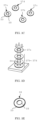
- FIG. 3 and FIG. 4 show processing etc. of components corresponding to each manufacturing step for the oxygen sensor of FIG. 2 .
- step S1 of FIG. 2 raw materials of the oxygen sensor element are mixed together and pulverized. More specifically, LnBa 2 Cu 3 O 7- ⁇ and Ln 2 BaCuO 5 (Ln denotes rare earth element) are mixed together as materials for the oxygen sensor element, and the mixed raw materials are pulverized using a ball mill or the like, resulting in the same sized grains.
- LnBa 2 Cu 3 O 7- ⁇ and Ln 2 BaCuO 5 Ln denotes rare earth element
- step S2 the materials obtained in the step described above are subjected to heat treatment (preliminary baking) at 900 to 1000°C.
- step S3 the preliminarily baked raw materials are pulverized using a ball mill or the like, resulting in the same sized grains, and then slurry is manufactured.
- a binder resin e.g., butyral resin (PVB)
- a dispersant e.g., sorbitan trioleate
- a plasticizer e.g., bis phthalate (2-ethylhexyl), DOP
- a diluting solvent e.g., 2-ethylhexanol
- step S4 a film is formed using a doctor blade so as to manufacture a green sheet of approximately 10 to 100 pm, for example.
- step S5 central circles 21a to 21d are punched out from a green sheet 20 using a mechanical punch etc.
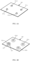
- Step S6 includes forming in the same sheet, a ring-shaped green sheet 27a positioned on the top layer of a laminated body described later and ring-shaped green sheets 27b to 27d stacked on the bottom layer thereof, and printing electrodes. More specifically, as shown in FIGS. 3A and 3B , electrode material made of silver (Ag) paste, for example, is screen printed in a ring shape along the inner periphery of the central circle 21a corresponding to the central circle of the ring-shaped green sheet 27a on the top surface of the laminated body, thus forming a positive electrode 25.
- silver (Ag) paste for example
- the electrode material is screen printed in a ring shape along an outer periphery 22a, which is at a distance equal to the radius of the ring-shaped green sheet 27a (namely, longitudinal length of the sensor element) from the center of the central circle 21a, thus forming a negative electrode 23.
- the other central circles 21b to 21d are left punched out without forming any electrodes.
- step S7 the green sheet 20 is punched out using a mechanical punch etc. along outer peripheries 22a to 22d (in the case of the central circle 21a, the outer periphery 22a becomes outer periphery of the negative electrode 23) stipulated at a distance equal to the radius of the ring-shaped green sheet (sensor element length) from the center of each of the central circles 21a to 21d.
- FIG. 3C illustrates the green sheets (ring-shaped green sheets) 27a to 27d each punched out in a ring shape from the green sheet 20.
- step S8 the ring-shaped green sheet 27a in which the electrodes 23 and 25 are formed in the inner and outer peripheries respectively is placed on the top part of the ring-shaped green sheets 27b to 27d in which electrodes are not provided, and a rod-like pin 31 is then inserted through center holes of the ring-shaped green sheets, thereby stacking them while aligning them, as illustrated in FIG. 3D .
- the laminated material of the ring-shaped sheets is then applied pressure using a uniaxial press, for example, thereby manufacturing a laminated body 33 having a predetermined thickness illustrated in FIG. 3E .
- the ring-shaped green sheet 27a is stacked on the three ring-shaped green sheets 27b to 27d, which become under layers thereof, thereby manufacturing a laminated body.
- the number of stacked layers is not limited thereto, and a necessary number of ring-shaped green sheets are stacked in accordance with thickness of the laminated body to be manufactured.
- each ring-shaped green sheet layer in the same sheet has been described, a method of forming together a plurality of the ring-shaped green sheet 27a to be the top surface of the same sheet may be used.
- step S9 the laminated body 33 is cut (diced) in accordance with product (sensor element) size.
- the laminated body 33 is adhered and fixed on to a guillotine stage 35, and while rotating the guillotine stage 35 around the circle center of the laminated body 33 every fixed angle (e.g., 10° at a time), a cutter 37 is moved a predetermined distance vertically downward, thereby cutting the laminated body 33.
- step S10 the sensor element 32 cut in the dicing step described above and divided into individual pieces as illustrated in FIG. 4B is baked in atmospheric air at, for example, 920°C for 10 hours. Note that de-binding may be carried out on the laminated body before baking, and annealing may be performed on the laminated body after baking.
- lead wires 47 and 49 are attached using a conductive paste, for example, to the positive electrode 43 and the negative electrode 45 of the sensor element 42 after baking, respectively, as illustrated in FIG. 4C .
- the method of attaching the lead wires is not limited to the above description. For example, instantly heating a joint using a pulse heat power source so as to solder or weld, or wire bonding through ultrasonic vibration or thermocompression bonding may be used.
- the length of the sensor element divided into individual pieces and baked as described above is 5 mm, for example, and the outer dimensions (size) of the oxygen sensor include, for example, a glass tube diameter of 5 mm, glass tube length of 20 mm, and air hole diameter of 2.5 mm.
- the sensor element with the dimensions described above makes the oxygen sensor exchangeable via the air holes of the glass tube, for example.
- paired electrodes 13 and 15 are formed on either end of the same surface (upper surface) in the longitudinal direction of the sensor element 12, paired electrodes may be formed on an upper surface of one end of the sensor element 12, and on an under surface of the other end of the sensor element 12.
- both side surfaces in the axial direction of the oxygen sensor 10 of FIG. 1 extend linearly between the positive electrode and the negative electrode in a planar view
- the sensor is not limited thereto.
- any one of shapes in which: either both side surfaces between the positive electrode and the negative electrode change into a curved form, or one side surface changes into a curved form and the other side surface changes linearly, in a planar view, may be used.
- the hot spot-type sensor element has a high resistance value on the opposite side to the travelling direction of O 2- ions, that is, the negative electrode side including a decreased number of O 2- ions. Therefore, the oxygen sensor according to the invention has the cross-sectional area with a shape that increases uniformly from the positive (+) electrode side toward the negative (-) electrode side, and the hot spot attempting to move to the negative electrode side may thus be led to a lower resistance side.
- a position that is at nearly equal distances from paired electrodes formed on either end of the sensor element may be a hot spot generating position, and prevention of damage to electrodes from heat emitted from a hot spot as the hot spot approaches the electrode and prevention of generation of cracks in a sensor element etc. caused by thermal stress due to thermal expansion are possible.
- the negative electrode may be made larger in size than the positive electrode.
- concentration of O 2- ions in the sensor element has changed, causing a hot spot to move to the negative electrode side, more effective heat radiation is facilitated on the negative side of the sensor element. Due to such heat radiation effect, the hot spot generating position may be kept away from the negative electrode side so as to be at a position nearly equal from both electrodes.
- the oxygen sensor according to the present invention is not limited to the embodiment described above, and various modifications are possible. Modified examples are described below.
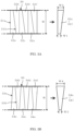
- FIGS. 5A and 5B show examples of manufacturing sensor elements by dicing a green sheet having a belt-like shape.
- a long green sheet 50 having width W in accordance with a longitudinal dimension (length in the longitudinal direction) of a sensor element is prepared, and the long green sheet 50 is cut along cutting lines in its width direction.
- the long green sheet 50 is diced along cutting lines 51a running in the width direction of the long green sheet 50 and cutting lines 51b running diagonally in the width direction.
- This allows manufacture of sensor elements 52a to 52f having shape of: the cross-sectional area thereof increasing uniformly from the one end toward the other end, and width W1 on the one end side smaller than width W2 on the other end side.
- FIG. 5B illustrates an example of dicing the long green sheet 50 along two cutting lines 53a and 53b running diagonally in the width direction of the long green sheet 50.
- This allows manufacture of sensor elements 54a to 54f having shape of: the cross-sectional area thereof increasing uniformly from the one end toward the other end, and width W3 on the one end side smaller than width W4 on the other end side.
- a sensor element 62 illustrated in FIG. 6A has an overall pyramid shape in which one end bottom surface has a smaller area than the other end bottom surface.
- lead lines 63 and 65 are attached to respective electrodes (omitted from the drawing) arranged on the one end bottom surface and the other end bottom surface.
- a sensor element 64 illustrated in FIG. 6B has an overall cone shape in which the one end bottom surface has a smaller area than the other end bottom surface.
- lead lines 67 and 69 are attached to respective electrodes, which are omitted from the drawing, arranged on the one end bottom surface and the other end bottom surface.
- FIG. 7A is an example where shape of a sensor element 72 is a T shape in a planar view. With the sensor element 72, cross-sectional area increases gradually or stepwisely from one side on which a lead wire 73 is attached, toward another side on which a lead wire 75 is attached.
- FIG. 7B is an example where shape of a sensor element 74 is an L shape in a planar view.
- cross-sectional area increases gradually or stepwisely from one side on which a lead wire 77 is attached, toward another side on which a lead wire 79 is attached.
- FIG. 8A illustrates an example punch-out pattern in the case of punching out a plurality of the T-shaped sensor element 72 of FIG. 7A from a single green sheet 70.
- FIG. 8B shows an example punch-out pattern in the case of punching out a plurality of the L-shaped sensor element 74 of FIG. 7B from a single green sheet 80.
- the number of sensor elements formed in a single green sheet may be maximized.
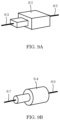
- a sensor element 82 of FIG. 9A has a shape in which two rectangular parallelepipeds having differing cross-sectional areas are connected. Moreover, lead wires 83 and 85 are attached to either end surface of the sensor element 82.
- a sensor element 84 of FIG. 9B has a shape in which two cylinders having differing cross-sectional areas are connected. Lead wires 87 and 89 are attached to either end surface of the sensor element 84. Accordingly, the cross-sectional area of the sensor element increases gradually or stepwisely from one end to the other end, even with the sensor element 82 of FIG. 9A and the sensor element 84 of FIG. 9B .
Landscapes
- Chemical & Material Sciences (AREA)
- Life Sciences & Earth Sciences (AREA)
- Health & Medical Sciences (AREA)
- Engineering & Computer Science (AREA)
- Immunology (AREA)
- Pathology (AREA)
- Physics & Mathematics (AREA)
- Analytical Chemistry (AREA)
- Biochemistry (AREA)
- General Health & Medical Sciences (AREA)
- General Physics & Mathematics (AREA)
- Electrochemistry (AREA)
- Chemical Kinetics & Catalysis (AREA)
- Manufacturing & Machinery (AREA)
- Ceramic Engineering (AREA)
- Mechanical Engineering (AREA)
- Combustion & Propulsion (AREA)
- Food Science & Technology (AREA)
- Medicinal Chemistry (AREA)
- Molecular Biology (AREA)
- Measuring Oxygen Concentration In Cells (AREA)
- Investigating Or Analyzing Materials By The Use Of Fluid Adsorption Or Reactions (AREA)
Claims (8)
- Hotspot-Typ-Sauerstoffsensor (10), umfassend ein Sensorelement (12, 42, 52a-52f, 54a-54f), das aus einem keramischen Sinterkörper gefertigt ist, zum Erfassen von Sauerstoffkonzentration basierend auf entweder einer Änderung eines elektrischen Stromwerts oder einer Änderung eines Widerstandswerts entsprechend einer an das Sensorelement (12, 42, 52a-52f, 54a-54f) angelegten Spannung, wobei das Sensorelement (12, 42, 52a-52f, 54a-54f) eine Form aufweist, bei der sich eine Querschnittsfläche (S1, S2) von einer Elektrodenseite zu der anderen Elektrodenseite von gepaarten Elektrodenteilen (13, 15, 43, 45) ändert, die an beiden Längsenden gebildet sind, dadurch gekennzeichnet, dass
die Querschnittsfläche (S1, S2) entweder gleichförmig oder allmählich von der einen Elektrodenseite zu der anderen Elektrodenseite hin zunimmt oder abnimmt, wobei von den gepaarten Elektrodenteilen (13, 15, 43, 45) ein Elektrodenteil, das auf einer Seite gebildet ist, auf der die Querschnittsfläche (S1) des Sensorelements (12, 42, 52a-52f, 54a-54f) größer ist, als eine negative Elektrode (15, 45) festgelegt ist, und ein Elektrodenteil, das auf einer anderen Seite gebildet ist, auf der die Querschnittsfläche (S2) kleiner ist, als eine positive Elektrode (13, 43) festgelegt ist. - Hotspot-Typ-Sauerstoffsensor nach Anspruch 1, wobei das Sensorelement (12, 42, 52a-52f, 54a-54f) eine konstante Stärke und eine Breite aufweist, die entweder gleichförmig oder allmählich von der einen Elektrodenseite zu der anderen Elektrodenseite hin zunimmt oder abnimmt.
- Hotspot-Typ-Sauerstoffsensor nach Anspruch 1, wobei das Sensorelement (12, 42, 52a-52f, 54a-54f) eine Stärke und Breite aufweist, die entweder gleichförmig oder allmählich von der einen Elektrodenseite zu der anderen Elektrodenseite hin zunimmt oder abnimmt.
- Hotspot-Typ-Sauerstoffsensor nach Anspruch 1, wobei entweder die negative Elektrode (15, 45) und die positive Elektrode (13, 43) nahezu die gleiche Größe aufweisen oder die Größe der negativen Elektrode (15, 45) größer ist als die der positiven Elektrode (13, 43).
- Hotspot-Typ-Sauerstoffsensor nach Anspruch 4, wobei entweder sowohl die negative Elektrode (15, 45) als auch die positive Elektrode (13, 43) auf derselben Seite des Sensorelements (12, 42, 52a-52f, 54a-54f) gebildet sind oder eine der negativen Elektrode (15, 45) oder der positiven Elektrode (13, 43) auf einer Oberseite des Sensorelements (12, 42, 52a-52f, 54a-54f) und die andere an einer Unterseite des Sensorelements (12, 42, 52a-52f, 54a-54f) gebildet ist.
- Herstellungsverfahren für einen Hotspot-Typ-Sauerstoffsensor (10), der ein Sensorelement (12, 42, 52a-52f, 54a-54f) beinhaltet, das aus einem keramischen Sinterkörper gefertigt ist, zum Erfassen entweder einer Änderung eines elektrischen Stromwerts oder einer Änderung eines Widerstandswerts, der gemessen wird, wenn eine Spannung an das Sensorelement (12, 42, 52a-52f, 54a-54f) angelegt wird, als Sauerstoffkonzentration, dadurch gekennzeichnet, dass es die folgenden Schritte umfasst:Herstellen eines grünen Blatts (20) aus einer Aufschlämmung, die durch Mischen von Rohstoffen des Sensorelements (12, 42, 52a-52f, 54a-54f) gebildet wird;Herstellen eines ringförmigen ersten grünen Blatts (27b~27d) durch Ausstanzen des grünen Blatts, um ein gestanztes Loch mit einem vorbestimmten Durchmesser zu bilden;Herstellen eines ringförmigen zweiten grünen Blatts (27a) durch Bilden von gürtelartig geformten Elektroden (23, 25) entlang eines Umfangs des gestanzten Lochs des ersten grünen Blatts (27b~27d) und eines ringförmigen Außenumfangs des ersten grünen Blatts (27b~27d);Herstellen eines ringförmigen laminierten Körpers (33) durch koaxiales Stapeln einer Vielzahl des ersten grünen Blatts (27b~27d) mit dem zweiten grünen Blatt (27a) als eine Oberseite;Schneiden des ringförmigen laminierten Körpers (33) entlang einer Vielzahl von diametralen virtuellen Linien des ringförmigen laminierten Körpers (33), der durch Drehen um die Achse des ringförmigen laminierten Körpers (33) in jedem festen Winkel in der Umfangsrichtung gebildet ist; undEinbrennen eines Sensorelements, das durch das Schneiden in einzelne Stücke unterteilt ist, und Bilden von gepaarten Elektroden (43, 45) an jedem Endteil in der Längsrichtung,wobei die Querschnittsfläche (S1, S2) entweder gleichförmig oder allmählich von der einen Elektrodenseite zu der anderen Elektrodenseite hin zunimmt oder abnimmt, und wobei von den gepaarten Elektrodenteilen (13, 15, 43, 45) ein Elektrodenteil, das auf einer Seite gebildet ist, auf der die Querschnittsfläche (S1) des Sensorelements (12, 42, 52a-52f, 54a-54f) größer ist, als eine negative Elektrode (15, 45) festgelegt ist, und ein Elektrodenteil, das auf einer anderen Seite gebildet ist, auf der die Querschnittsfläche (S2) kleiner ist, als eine positive Elektrode (13, 43) festgelegt ist.
- Herstellungsverfahren für einen Hotspot-Typ-Sauerstoffsensor nach Anspruch 6, wobei in dem Schritt eines Schneidens des ringförmigen laminierten Körpers (33) ein Schneiden des laminierten Körpers entweder durch Drehen des laminierten Körpers um seine Achse um jeden festen Winkel in der Umfangsrichtung und Bewegen eines Schneidteils, das an einem oberen Teil des laminierten Körpers angeordnet ist, um einen vorbestimmten Abstand vertikal nach unten synchron mit dem Drehen durchgeführt wird, oder durch Fixieren des laminierten Körpers und Bewegen eines Schneidteils, das an einem oberen Teil des laminierten Körpers angeordnet ist, um einen vorbestimmten Abstand vertikal nach unten, während es um jeden festen Winkel in der Umfangsrichtung um die Achse des laminierten Körpers gedreht wird.
- Herstellungsverfahren für einen Hotspot-Typ-Sauerstoffsensor (10), der ein Sensorelement (12, 42, 52a-52f, 54a-54f) beinhaltet, das aus einem keramischen Sinterkörper gefertigt ist, zum Erfassen entweder einer Änderung eines elektrischen Stromwerts oder einer Änderung eines Widerstandswerts, der gemessen wird, wenn eine Spannung an das Sensorelement (12, 42, 52a-52f, 54a-54f) angelegt wird, als Sauerstoffkonzentration, dadurch gekennzeichnet, dass es die folgenden Schritte umfasst:Herstellen eines langen grünen Blatts (50) aus einer Aufschlämmung, die durch Mischen von Rohstoffen des Sensorelements gebildet wird;Herstellen eines Sensorelementstücks (52a-52f, 54a-54f) mit nahezu trapezförmiger Form in einer planaren Ansicht durch Schneiden des grünen Blatts in einer Zickzackform in vorbestimmten Intervallen in einer Richtung, die eine Längsrichtung des grünen Blatts kreuzt; undBiegen des Sensorelementstücks (52a-52f, 54a-54f) und Bilden gepaarter Elektroden (43, 45) an jedem Endteil in der Längsrichtung,wobei die Querschnittsfläche (S1, S2) entweder gleichförmig oder allmählich von der einen Elektrodenseite zu der anderen Elektrodenseite hin zunimmt oder abnimmt, und wobei von den gepaarten Elektrodenteilen (13, 15, 43, 45) ein Elektrodenteil, das auf einer Seite gebildet ist, auf der die Querschnittsfläche (S1) des Sensorelements (12, 42, 52a-52f, 54a-54f) größer ist, als eine negative Elektrode (15, 45) festgelegt ist, und ein Elektrodenteil, das auf einer anderen Seite gebildet ist, auf der die Querschnittsfläche (S2) kleiner ist, als eine positive Elektrode (13, 43) festgelegt ist.
Applications Claiming Priority (2)
| Application Number | Priority Date | Filing Date | Title |
|---|---|---|---|
| JP2018057303A JP7000222B2 (ja) | 2018-03-23 | 2018-03-23 | ガスセンサおよびその製造方法 |
| PCT/JP2019/011698 WO2019182011A1 (ja) | 2018-03-23 | 2019-03-20 | ガスセンサおよびその製造方法 |
Publications (3)
| Publication Number | Publication Date |
|---|---|
| EP3770592A1 EP3770592A1 (de) | 2021-01-27 |
| EP3770592A4 EP3770592A4 (de) | 2021-12-29 |
| EP3770592B1 true EP3770592B1 (de) | 2023-09-27 |
Family
ID=67987323
Family Applications (1)
| Application Number | Title | Priority Date | Filing Date |
|---|---|---|---|
| EP19770302.8A Active EP3770592B1 (de) | 2018-03-23 | 2019-03-20 | Gassensor und herstellungsverfahren dafür |
Country Status (5)
| Country | Link |
|---|---|
| US (2) | US20210010963A1 (de) |
| EP (1) | EP3770592B1 (de) |
| JP (1) | JP7000222B2 (de) |
| CN (1) | CN111886494B (de) |
| WO (1) | WO2019182011A1 (de) |
Families Citing this family (3)
| Publication number | Priority date | Publication date | Assignee | Title |
|---|---|---|---|---|
| JP2019174440A (ja) * | 2018-01-31 | 2019-10-10 | Koa株式会社 | 酸素センサ素子 |
| JP7670270B2 (ja) | 2021-06-17 | 2025-04-30 | 国立大学法人長岡技術科学大学 | 抵抗型酸素ガスセンサ及び酸素センサ装置 |
| JP7643685B2 (ja) | 2021-06-17 | 2025-03-11 | 国立大学法人長岡技術科学大学 | 酸素センサ素子およびその製造方法 |
Family Cites Families (18)
| Publication number | Priority date | Publication date | Assignee | Title |
|---|---|---|---|---|
| JPS52150696A (en) * | 1976-06-09 | 1977-12-14 | Nippon Soken | Detector for gas composition |
| JPH04115056U (ja) * | 1991-03-28 | 1992-10-12 | 横河電機株式会社 | セラミツクガスセンサ |
| JPH1073549A (ja) | 1996-08-30 | 1998-03-17 | Tokyo Gas Co Ltd | 自己発熱式酸素センサ |
| JP2000019143A (ja) * | 1998-06-30 | 2000-01-21 | Toyota Motor Corp | 酸素濃度検出素子 |
| JP2000055857A (ja) * | 1998-08-03 | 2000-02-25 | Tokyo Gas Co Ltd | 酸素センサ素子 |
| JP2000055855A (ja) * | 1998-08-04 | 2000-02-25 | Tokyo Gas Co Ltd | 自己発熱型ガスセンサ |
| US20030146093A1 (en) * | 2002-02-05 | 2003-08-07 | Kyocera Corporation | Oxygen sensor |
| JP3935754B2 (ja) * | 2002-03-27 | 2007-06-27 | 京セラ株式会社 | 酸素センサ素子 |
| JP2004226310A (ja) * | 2003-01-24 | 2004-08-12 | Kyocera Corp | 酸素センサ |
| WO2005095924A1 (en) * | 2004-03-31 | 2005-10-13 | Agency For Science, Technology And Research | A sensor for measuring gas permeability of a test material |
| US7278327B2 (en) * | 2004-07-26 | 2007-10-09 | New Jersey Institute Of Technology | Film based position and pressure sensor |
| JP4714867B2 (ja) | 2005-09-21 | 2011-06-29 | 国立大学法人長岡技術科学大学 | 酸素センサ |
| JP2007273191A (ja) * | 2006-03-30 | 2007-10-18 | Toyota Motor Corp | 燃料電池 |
| KR101195918B1 (ko) * | 2008-01-29 | 2012-10-30 | 쿄세라 코포레이션 | 세라믹 히터 및 글로우 플러그 |
| CN102954993B (zh) * | 2011-08-29 | 2015-07-22 | 比亚迪股份有限公司 | 一种氧传感器及其制备方法 |
| JP6643647B2 (ja) * | 2015-03-19 | 2020-02-12 | パナソニックIpマネジメント株式会社 | 感圧素子 |
| JP6523878B2 (ja) * | 2015-08-31 | 2019-06-05 | 日本特殊陶業株式会社 | ガスセンサ制御装置 |
| JP7000221B2 (ja) * | 2018-03-23 | 2022-01-19 | Koa株式会社 | ガスセンサおよびその製造方法 |
-
2018
- 2018-03-23 JP JP2018057303A patent/JP7000222B2/ja active Active
-
2019
- 2019-03-20 US US17/040,278 patent/US20210010963A1/en not_active Abandoned
- 2019-03-20 WO PCT/JP2019/011698 patent/WO2019182011A1/ja not_active Ceased
- 2019-03-20 CN CN201980020754.4A patent/CN111886494B/zh active Active
- 2019-03-20 EP EP19770302.8A patent/EP3770592B1/de active Active
-
2023
- 2023-06-07 US US18/206,816 patent/US12493010B2/en active Active
Also Published As
| Publication number | Publication date |
|---|---|
| WO2019182011A1 (ja) | 2019-09-26 |
| EP3770592A1 (de) | 2021-01-27 |
| JP2019168367A (ja) | 2019-10-03 |
| CN111886494A (zh) | 2020-11-03 |
| EP3770592A4 (de) | 2021-12-29 |
| JP7000222B2 (ja) | 2022-01-19 |
| US20210010963A1 (en) | 2021-01-14 |
| US20230349851A1 (en) | 2023-11-02 |
| CN111886494B (zh) | 2024-06-04 |
| US12493010B2 (en) | 2025-12-09 |
Similar Documents
| Publication | Publication Date | Title |
|---|---|---|
| US12493010B2 (en) | Gas sensor | |
| US7598660B2 (en) | Monolithic piezoelectric element | |
| KR101575614B1 (ko) | 유전체 세라믹 및 적층 세라믹 콘덴서 | |
| CN107437465B (zh) | 层叠陶瓷电容器 | |
| JP6314994B2 (ja) | 積層型セラミック電子部品 | |
| KR101464185B1 (ko) | 적층 세라믹 콘덴서 및 적층 세라믹 콘덴서의 제조방법 | |
| KR101697950B1 (ko) | 적층형 세라믹 전자 부품 | |
| JP4854831B2 (ja) | 積層型圧電アクチュエータ | |
| KR101800211B1 (ko) | 적층 세라믹 콘덴서 | |
| US11977042B2 (en) | Gas sensor and method for manufacturing same | |
| CN116504438B (zh) | 电介质组合物及层叠陶瓷电子零件 | |
| EP3002272A1 (de) | Hitzebeständiges element und verfahren zur herstellung davon | |
| JP2023120451A (ja) | 積層型コイル部品 | |
| US20230046574A1 (en) | Multilayer ceramic capacitor and method for producing the same | |
| JP4637671B2 (ja) | セラミック積層体及びそれを具備するガスセンサ | |
| JP5409703B2 (ja) | 積層型圧電アクチュエータの製造方法 | |
| JP6567700B2 (ja) | 温度センサ素子 | |
| US12633458B2 (en) | Multilayer ceramic capacitor and method for producing the same | |
| US20250296885A1 (en) | Dielectric composition and electronic component | |
| JP2007254281A (ja) | 焼結体の製造方法、焼結体、焼結用部材、セラミック多層基板の製造方法およびセラミック多層基板 | |
| JP2019120708A (ja) | 温度センサ素子 | |
| JP2006269982A (ja) | 圧電素子の製造方法及び圧電素子 | |
| CN115206629A (zh) | 线圈部件 |
Legal Events
| Date | Code | Title | Description |
|---|---|---|---|
| STAA | Information on the status of an ep patent application or granted ep patent |
Free format text: STATUS: THE INTERNATIONAL PUBLICATION HAS BEEN MADE |
|
| PUAI | Public reference made under article 153(3) epc to a published international application that has entered the european phase |
Free format text: ORIGINAL CODE: 0009012 |
|
| STAA | Information on the status of an ep patent application or granted ep patent |
Free format text: STATUS: REQUEST FOR EXAMINATION WAS MADE |
|
| 17P | Request for examination filed |
Effective date: 20201015 |
|
| AK | Designated contracting states |
Kind code of ref document: A1 Designated state(s): AL AT BE BG CH CY CZ DE DK EE ES FI FR GB GR HR HU IE IS IT LI LT LU LV MC MK MT NL NO PL PT RO RS SE SI SK SM TR |
|
| AX | Request for extension of the european patent |
Extension state: BA ME |
|
| DAV | Request for validation of the european patent (deleted) | ||
| DAX | Request for extension of the european patent (deleted) | ||
| A4 | Supplementary search report drawn up and despatched |
Effective date: 20211129 |
|
| RIC1 | Information provided on ipc code assigned before grant |
Ipc: G01N 27/416 20060101ALI20211123BHEP Ipc: G01N 27/406 20060101ALI20211123BHEP Ipc: G01N 27/404 20060101ALI20211123BHEP Ipc: G01N 27/12 20060101AFI20211123BHEP |
|
| RIC1 | Information provided on ipc code assigned before grant |
Ipc: G01N 27/406 20060101ALI20230427BHEP Ipc: G01N 27/12 20060101AFI20230427BHEP |
|
| GRAP | Despatch of communication of intention to grant a patent |
Free format text: ORIGINAL CODE: EPIDOSNIGR1 |
|
| STAA | Information on the status of an ep patent application or granted ep patent |
Free format text: STATUS: GRANT OF PATENT IS INTENDED |
|
| INTG | Intention to grant announced |
Effective date: 20230616 |
|
| GRAS | Grant fee paid |
Free format text: ORIGINAL CODE: EPIDOSNIGR3 |
|
| GRAA | (expected) grant |
Free format text: ORIGINAL CODE: 0009210 |
|
| STAA | Information on the status of an ep patent application or granted ep patent |
Free format text: STATUS: THE PATENT HAS BEEN GRANTED |
|
| AK | Designated contracting states |
Kind code of ref document: B1 Designated state(s): AL AT BE BG CH CY CZ DE DK EE ES FI FR GB GR HR HU IE IS IT LI LT LU LV MC MK MT NL NO PL PT RO RS SE SI SK SM TR |
|
| REG | Reference to a national code |
Ref country code: GB Ref legal event code: FG4D |
|
| REG | Reference to a national code |
Ref country code: CH Ref legal event code: EP |
|
| REG | Reference to a national code |
Ref country code: DE Ref legal event code: R096 Ref document number: 602019038264 Country of ref document: DE |
|
| REG | Reference to a national code |
Ref country code: IE Ref legal event code: FG4D |
|
| REG | Reference to a national code |
Ref country code: LT Ref legal event code: MG9D |
|
| PG25 | Lapsed in a contracting state [announced via postgrant information from national office to epo] |
Ref country code: GR Free format text: LAPSE BECAUSE OF FAILURE TO SUBMIT A TRANSLATION OF THE DESCRIPTION OR TO PAY THE FEE WITHIN THE PRESCRIBED TIME-LIMIT Effective date: 20231228 |
|
| PG25 | Lapsed in a contracting state [announced via postgrant information from national office to epo] |
Ref country code: SE Free format text: LAPSE BECAUSE OF FAILURE TO SUBMIT A TRANSLATION OF THE DESCRIPTION OR TO PAY THE FEE WITHIN THE PRESCRIBED TIME-LIMIT Effective date: 20230927 Ref country code: RS Free format text: LAPSE BECAUSE OF FAILURE TO SUBMIT A TRANSLATION OF THE DESCRIPTION OR TO PAY THE FEE WITHIN THE PRESCRIBED TIME-LIMIT Effective date: 20230927 Ref country code: NO Free format text: LAPSE BECAUSE OF FAILURE TO SUBMIT A TRANSLATION OF THE DESCRIPTION OR TO PAY THE FEE WITHIN THE PRESCRIBED TIME-LIMIT Effective date: 20231227 Ref country code: LV Free format text: LAPSE BECAUSE OF FAILURE TO SUBMIT A TRANSLATION OF THE DESCRIPTION OR TO PAY THE FEE WITHIN THE PRESCRIBED TIME-LIMIT Effective date: 20230927 Ref country code: LT Free format text: LAPSE BECAUSE OF FAILURE TO SUBMIT A TRANSLATION OF THE DESCRIPTION OR TO PAY THE FEE WITHIN THE PRESCRIBED TIME-LIMIT Effective date: 20230927 Ref country code: HR Free format text: LAPSE BECAUSE OF FAILURE TO SUBMIT A TRANSLATION OF THE DESCRIPTION OR TO PAY THE FEE WITHIN THE PRESCRIBED TIME-LIMIT Effective date: 20230927 Ref country code: GR Free format text: LAPSE BECAUSE OF FAILURE TO SUBMIT A TRANSLATION OF THE DESCRIPTION OR TO PAY THE FEE WITHIN THE PRESCRIBED TIME-LIMIT Effective date: 20231228 Ref country code: FI Free format text: LAPSE BECAUSE OF FAILURE TO SUBMIT A TRANSLATION OF THE DESCRIPTION OR TO PAY THE FEE WITHIN THE PRESCRIBED TIME-LIMIT Effective date: 20230927 |
|
| REG | Reference to a national code |
Ref country code: NL Ref legal event code: MP Effective date: 20230927 |
|
| REG | Reference to a national code |
Ref country code: AT Ref legal event code: MK05 Ref document number: 1615869 Country of ref document: AT Kind code of ref document: T Effective date: 20230927 |
|
| PG25 | Lapsed in a contracting state [announced via postgrant information from national office to epo] |
Ref country code: NL Free format text: LAPSE BECAUSE OF FAILURE TO SUBMIT A TRANSLATION OF THE DESCRIPTION OR TO PAY THE FEE WITHIN THE PRESCRIBED TIME-LIMIT Effective date: 20230927 |
|
| PG25 | Lapsed in a contracting state [announced via postgrant information from national office to epo] |
Ref country code: IS Free format text: LAPSE BECAUSE OF FAILURE TO SUBMIT A TRANSLATION OF THE DESCRIPTION OR TO PAY THE FEE WITHIN THE PRESCRIBED TIME-LIMIT Effective date: 20240127 |
|
| PG25 | Lapsed in a contracting state [announced via postgrant information from national office to epo] |
Ref country code: AT Free format text: LAPSE BECAUSE OF FAILURE TO SUBMIT A TRANSLATION OF THE DESCRIPTION OR TO PAY THE FEE WITHIN THE PRESCRIBED TIME-LIMIT Effective date: 20230927 |
|
| PG25 | Lapsed in a contracting state [announced via postgrant information from national office to epo] |
Ref country code: ES Free format text: LAPSE BECAUSE OF FAILURE TO SUBMIT A TRANSLATION OF THE DESCRIPTION OR TO PAY THE FEE WITHIN THE PRESCRIBED TIME-LIMIT Effective date: 20230927 |
|
| PG25 | Lapsed in a contracting state [announced via postgrant information from national office to epo] |
Ref country code: SM Free format text: LAPSE BECAUSE OF FAILURE TO SUBMIT A TRANSLATION OF THE DESCRIPTION OR TO PAY THE FEE WITHIN THE PRESCRIBED TIME-LIMIT Effective date: 20230927 Ref country code: RO Free format text: LAPSE BECAUSE OF FAILURE TO SUBMIT A TRANSLATION OF THE DESCRIPTION OR TO PAY THE FEE WITHIN THE PRESCRIBED TIME-LIMIT Effective date: 20230927 Ref country code: IS Free format text: LAPSE BECAUSE OF FAILURE TO SUBMIT A TRANSLATION OF THE DESCRIPTION OR TO PAY THE FEE WITHIN THE PRESCRIBED TIME-LIMIT Effective date: 20240127 Ref country code: ES Free format text: LAPSE BECAUSE OF FAILURE TO SUBMIT A TRANSLATION OF THE DESCRIPTION OR TO PAY THE FEE WITHIN THE PRESCRIBED TIME-LIMIT Effective date: 20230927 Ref country code: EE Free format text: LAPSE BECAUSE OF FAILURE TO SUBMIT A TRANSLATION OF THE DESCRIPTION OR TO PAY THE FEE WITHIN THE PRESCRIBED TIME-LIMIT Effective date: 20230927 Ref country code: CZ Free format text: LAPSE BECAUSE OF FAILURE TO SUBMIT A TRANSLATION OF THE DESCRIPTION OR TO PAY THE FEE WITHIN THE PRESCRIBED TIME-LIMIT Effective date: 20230927 Ref country code: AT Free format text: LAPSE BECAUSE OF FAILURE TO SUBMIT A TRANSLATION OF THE DESCRIPTION OR TO PAY THE FEE WITHIN THE PRESCRIBED TIME-LIMIT Effective date: 20230927 Ref country code: PT Free format text: LAPSE BECAUSE OF FAILURE TO SUBMIT A TRANSLATION OF THE DESCRIPTION OR TO PAY THE FEE WITHIN THE PRESCRIBED TIME-LIMIT Effective date: 20240129 Ref country code: SK Free format text: LAPSE BECAUSE OF FAILURE TO SUBMIT A TRANSLATION OF THE DESCRIPTION OR TO PAY THE FEE WITHIN THE PRESCRIBED TIME-LIMIT Effective date: 20230927 |
|
| PG25 | Lapsed in a contracting state [announced via postgrant information from national office to epo] |
Ref country code: PL Free format text: LAPSE BECAUSE OF FAILURE TO SUBMIT A TRANSLATION OF THE DESCRIPTION OR TO PAY THE FEE WITHIN THE PRESCRIBED TIME-LIMIT Effective date: 20230927 Ref country code: IT Free format text: LAPSE BECAUSE OF FAILURE TO SUBMIT A TRANSLATION OF THE DESCRIPTION OR TO PAY THE FEE WITHIN THE PRESCRIBED TIME-LIMIT Effective date: 20230927 |
|
| REG | Reference to a national code |
Ref country code: DE Ref legal event code: R097 Ref document number: 602019038264 Country of ref document: DE |
|
| PG25 | Lapsed in a contracting state [announced via postgrant information from national office to epo] |
Ref country code: DK Free format text: LAPSE BECAUSE OF FAILURE TO SUBMIT A TRANSLATION OF THE DESCRIPTION OR TO PAY THE FEE WITHIN THE PRESCRIBED TIME-LIMIT Effective date: 20230927 |
|
| PG25 | Lapsed in a contracting state [announced via postgrant information from national office to epo] |
Ref country code: DK Free format text: LAPSE BECAUSE OF FAILURE TO SUBMIT A TRANSLATION OF THE DESCRIPTION OR TO PAY THE FEE WITHIN THE PRESCRIBED TIME-LIMIT Effective date: 20230927 |
|
| PLBE | No opposition filed within time limit |
Free format text: ORIGINAL CODE: 0009261 |
|
| STAA | Information on the status of an ep patent application or granted ep patent |
Free format text: STATUS: NO OPPOSITION FILED WITHIN TIME LIMIT |
|
| 26N | No opposition filed |
Effective date: 20240628 |
|
| PG25 | Lapsed in a contracting state [announced via postgrant information from national office to epo] |
Ref country code: SI Free format text: LAPSE BECAUSE OF FAILURE TO SUBMIT A TRANSLATION OF THE DESCRIPTION OR TO PAY THE FEE WITHIN THE PRESCRIBED TIME-LIMIT Effective date: 20230927 |
|
| PG25 | Lapsed in a contracting state [announced via postgrant information from national office to epo] |
Ref country code: SI Free format text: LAPSE BECAUSE OF FAILURE TO SUBMIT A TRANSLATION OF THE DESCRIPTION OR TO PAY THE FEE WITHIN THE PRESCRIBED TIME-LIMIT Effective date: 20230927 |
|
| REG | Reference to a national code |
Ref country code: CH Ref legal event code: PL |
|
| PG25 | Lapsed in a contracting state [announced via postgrant information from national office to epo] |
Ref country code: BG Free format text: LAPSE BECAUSE OF FAILURE TO SUBMIT A TRANSLATION OF THE DESCRIPTION OR TO PAY THE FEE WITHIN THE PRESCRIBED TIME-LIMIT Effective date: 20230927 |
|
| PG25 | Lapsed in a contracting state [announced via postgrant information from national office to epo] |
Ref country code: LU Free format text: LAPSE BECAUSE OF NON-PAYMENT OF DUE FEES Effective date: 20240320 |
|
| PG25 | Lapsed in a contracting state [announced via postgrant information from national office to epo] |
Ref country code: MC Free format text: LAPSE BECAUSE OF FAILURE TO SUBMIT A TRANSLATION OF THE DESCRIPTION OR TO PAY THE FEE WITHIN THE PRESCRIBED TIME-LIMIT Effective date: 20230927 |
|
| GBPC | Gb: european patent ceased through non-payment of renewal fee |
Effective date: 20240320 |
|
| PG25 | Lapsed in a contracting state [announced via postgrant information from national office to epo] |
Ref country code: MC Free format text: LAPSE BECAUSE OF FAILURE TO SUBMIT A TRANSLATION OF THE DESCRIPTION OR TO PAY THE FEE WITHIN THE PRESCRIBED TIME-LIMIT Effective date: 20230927 Ref country code: LU Free format text: LAPSE BECAUSE OF NON-PAYMENT OF DUE FEES Effective date: 20240320 Ref country code: BG Free format text: LAPSE BECAUSE OF FAILURE TO SUBMIT A TRANSLATION OF THE DESCRIPTION OR TO PAY THE FEE WITHIN THE PRESCRIBED TIME-LIMIT Effective date: 20230927 |
|
| REG | Reference to a national code |
Ref country code: BE Ref legal event code: MM Effective date: 20240331 |
|
| PG25 | Lapsed in a contracting state [announced via postgrant information from national office to epo] |
Ref country code: BE Free format text: LAPSE BECAUSE OF NON-PAYMENT OF DUE FEES Effective date: 20240331 |
|
| PG25 | Lapsed in a contracting state [announced via postgrant information from national office to epo] |
Ref country code: GB Free format text: LAPSE BECAUSE OF NON-PAYMENT OF DUE FEES Effective date: 20240320 |
|
| PG25 | Lapsed in a contracting state [announced via postgrant information from national office to epo] |
Ref country code: FR Free format text: LAPSE BECAUSE OF NON-PAYMENT OF DUE FEES Effective date: 20240331 |
|
| PG25 | Lapsed in a contracting state [announced via postgrant information from national office to epo] |
Ref country code: IE Free format text: LAPSE BECAUSE OF NON-PAYMENT OF DUE FEES Effective date: 20240320 |
|
| PG25 | Lapsed in a contracting state [announced via postgrant information from national office to epo] |
Ref country code: IE Free format text: LAPSE BECAUSE OF NON-PAYMENT OF DUE FEES Effective date: 20240320 Ref country code: GB Free format text: LAPSE BECAUSE OF NON-PAYMENT OF DUE FEES Effective date: 20240320 Ref country code: FR Free format text: LAPSE BECAUSE OF NON-PAYMENT OF DUE FEES Effective date: 20240331 Ref country code: BE Free format text: LAPSE BECAUSE OF NON-PAYMENT OF DUE FEES Effective date: 20240331 Ref country code: CH Free format text: LAPSE BECAUSE OF NON-PAYMENT OF DUE FEES Effective date: 20240331 |
|
| PG25 | Lapsed in a contracting state [announced via postgrant information from national office to epo] |
Ref country code: CY Free format text: LAPSE BECAUSE OF FAILURE TO SUBMIT A TRANSLATION OF THE DESCRIPTION OR TO PAY THE FEE WITHIN THE PRESCRIBED TIME-LIMIT; INVALID AB INITIO Effective date: 20190320 |
|
| PG25 | Lapsed in a contracting state [announced via postgrant information from national office to epo] |
Ref country code: HU Free format text: LAPSE BECAUSE OF FAILURE TO SUBMIT A TRANSLATION OF THE DESCRIPTION OR TO PAY THE FEE WITHIN THE PRESCRIBED TIME-LIMIT; INVALID AB INITIO Effective date: 20190320 |
|
| PG25 | Lapsed in a contracting state [announced via postgrant information from national office to epo] |
Ref country code: TR Free format text: LAPSE BECAUSE OF FAILURE TO SUBMIT A TRANSLATION OF THE DESCRIPTION OR TO PAY THE FEE WITHIN THE PRESCRIBED TIME-LIMIT Effective date: 20230927 |
|
| PGFP | Annual fee paid to national office [announced via postgrant information from national office to epo] |
Ref country code: DE Payment date: 20260128 Year of fee payment: 8 |