EP3765327B1 - Kontakteinheit - Google Patents
Kontakteinheit Download PDFInfo
- Publication number
- EP3765327B1 EP3765327B1 EP19713369.7A EP19713369A EP3765327B1 EP 3765327 B1 EP3765327 B1 EP 3765327B1 EP 19713369 A EP19713369 A EP 19713369A EP 3765327 B1 EP3765327 B1 EP 3765327B1
- Authority
- EP
- European Patent Office
- Prior art keywords
- contact
- charging
- contact unit
- contact device
- pivot bearing
- Prior art date
- Legal status (The legal status is an assumption and is not a legal conclusion. Google has not performed a legal analysis and makes no representation as to the accuracy of the status listed.)
- Active
Links
Images


Classifications
-
- B—PERFORMING OPERATIONS; TRANSPORTING
- B60—VEHICLES IN GENERAL
- B60L—PROPULSION OF ELECTRICALLY-PROPELLED VEHICLES; SUPPLYING ELECTRIC POWER FOR AUXILIARY EQUIPMENT OF ELECTRICALLY-PROPELLED VEHICLES; ELECTRODYNAMIC BRAKE SYSTEMS FOR VEHICLES IN GENERAL; MAGNETIC SUSPENSION OR LEVITATION FOR VEHICLES; MONITORING OPERATING VARIABLES OF ELECTRICALLY-PROPELLED VEHICLES; ELECTRIC SAFETY DEVICES FOR ELECTRICALLY-PROPELLED VEHICLES
- B60L5/00—Current collectors for power supply lines of electrically-propelled vehicles
- B60L5/36—Current collectors for power supply lines of electrically-propelled vehicles with means for collecting current simultaneously from more than one conductor, e.g. from more than one phase
-
- B—PERFORMING OPERATIONS; TRANSPORTING
- B60—VEHICLES IN GENERAL
- B60L—PROPULSION OF ELECTRICALLY-PROPELLED VEHICLES; SUPPLYING ELECTRIC POWER FOR AUXILIARY EQUIPMENT OF ELECTRICALLY-PROPELLED VEHICLES; ELECTRODYNAMIC BRAKE SYSTEMS FOR VEHICLES IN GENERAL; MAGNETIC SUSPENSION OR LEVITATION FOR VEHICLES; MONITORING OPERATING VARIABLES OF ELECTRICALLY-PROPELLED VEHICLES; ELECTRIC SAFETY DEVICES FOR ELECTRICALLY-PROPELLED VEHICLES
- B60L5/00—Current collectors for power supply lines of electrically-propelled vehicles
- B60L5/18—Current collectors for power supply lines of electrically-propelled vehicles using bow-type collectors in contact with trolley wire
- B60L5/22—Supporting means for the contact bow
- B60L5/24—Pantographs
-
- B—PERFORMING OPERATIONS; TRANSPORTING
- B60—VEHICLES IN GENERAL
- B60L—PROPULSION OF ELECTRICALLY-PROPELLED VEHICLES; SUPPLYING ELECTRIC POWER FOR AUXILIARY EQUIPMENT OF ELECTRICALLY-PROPELLED VEHICLES; ELECTRODYNAMIC BRAKE SYSTEMS FOR VEHICLES IN GENERAL; MAGNETIC SUSPENSION OR LEVITATION FOR VEHICLES; MONITORING OPERATING VARIABLES OF ELECTRICALLY-PROPELLED VEHICLES; ELECTRIC SAFETY DEVICES FOR ELECTRICALLY-PROPELLED VEHICLES
- B60L5/00—Current collectors for power supply lines of electrically-propelled vehicles
- B60L5/42—Current collectors for power supply lines of electrically-propelled vehicles for collecting current from individual contact pieces connected to the power supply line
-
- B—PERFORMING OPERATIONS; TRANSPORTING
- B60—VEHICLES IN GENERAL
- B60L—PROPULSION OF ELECTRICALLY-PROPELLED VEHICLES; SUPPLYING ELECTRIC POWER FOR AUXILIARY EQUIPMENT OF ELECTRICALLY-PROPELLED VEHICLES; ELECTRODYNAMIC BRAKE SYSTEMS FOR VEHICLES IN GENERAL; MAGNETIC SUSPENSION OR LEVITATION FOR VEHICLES; MONITORING OPERATING VARIABLES OF ELECTRICALLY-PROPELLED VEHICLES; ELECTRIC SAFETY DEVICES FOR ELECTRICALLY-PROPELLED VEHICLES
- B60L53/00—Methods of charging batteries, specially adapted for electric vehicles; Charging stations or on-board charging equipment therefor; Exchange of energy storage elements in electric vehicles
- B60L53/10—Methods of charging batteries, specially adapted for electric vehicles; Charging stations or on-board charging equipment therefor; Exchange of energy storage elements in electric vehicles characterised by the energy transfer between the charging station and the vehicle
- B60L53/11—DC charging controlled by the charging station, e.g. mode 4
-
- B—PERFORMING OPERATIONS; TRANSPORTING
- B60—VEHICLES IN GENERAL
- B60L—PROPULSION OF ELECTRICALLY-PROPELLED VEHICLES; SUPPLYING ELECTRIC POWER FOR AUXILIARY EQUIPMENT OF ELECTRICALLY-PROPELLED VEHICLES; ELECTRODYNAMIC BRAKE SYSTEMS FOR VEHICLES IN GENERAL; MAGNETIC SUSPENSION OR LEVITATION FOR VEHICLES; MONITORING OPERATING VARIABLES OF ELECTRICALLY-PROPELLED VEHICLES; ELECTRIC SAFETY DEVICES FOR ELECTRICALLY-PROPELLED VEHICLES
- B60L53/00—Methods of charging batteries, specially adapted for electric vehicles; Charging stations or on-board charging equipment therefor; Exchange of energy storage elements in electric vehicles
- B60L53/10—Methods of charging batteries, specially adapted for electric vehicles; Charging stations or on-board charging equipment therefor; Exchange of energy storage elements in electric vehicles characterised by the energy transfer between the charging station and the vehicle
- B60L53/14—Conductive energy transfer
- B60L53/16—Connectors, e.g. plugs or sockets, specially adapted for charging electric vehicles
-
- B—PERFORMING OPERATIONS; TRANSPORTING
- B60—VEHICLES IN GENERAL
- B60L—PROPULSION OF ELECTRICALLY-PROPELLED VEHICLES; SUPPLYING ELECTRIC POWER FOR AUXILIARY EQUIPMENT OF ELECTRICALLY-PROPELLED VEHICLES; ELECTRODYNAMIC BRAKE SYSTEMS FOR VEHICLES IN GENERAL; MAGNETIC SUSPENSION OR LEVITATION FOR VEHICLES; MONITORING OPERATING VARIABLES OF ELECTRICALLY-PROPELLED VEHICLES; ELECTRIC SAFETY DEVICES FOR ELECTRICALLY-PROPELLED VEHICLES
- B60L53/00—Methods of charging batteries, specially adapted for electric vehicles; Charging stations or on-board charging equipment therefor; Exchange of energy storage elements in electric vehicles
- B60L53/30—Constructional details of charging stations
- B60L53/35—Means for automatic or assisted adjustment of the relative position of charging devices and vehicles
-
- H—ELECTRICITY
- H01—ELECTRIC ELEMENTS
- H01R—ELECTRICALLY-CONDUCTIVE CONNECTIONS; STRUCTURAL ASSOCIATIONS OF A PLURALITY OF MUTUALLY-INSULATED ELECTRICAL CONNECTING ELEMENTS; COUPLING DEVICES; CURRENT COLLECTORS
- H01R13/00—Details of coupling devices of the kinds covered by groups H01R12/70 or H01R24/00 - H01R33/00
- H01R13/62—Means for facilitating engagement or disengagement of coupling parts or for holding them in engagement
- H01R13/629—Additional means for facilitating engagement or disengagement of coupling parts, e.g. aligning or guiding means, levers, gas pressure electrical locking indicators, manufacturing tolerances
- H01R13/631—Additional means for facilitating engagement or disengagement of coupling parts, e.g. aligning or guiding means, levers, gas pressure electrical locking indicators, manufacturing tolerances for engagement only
-
- B—PERFORMING OPERATIONS; TRANSPORTING
- B60—VEHICLES IN GENERAL
- B60L—PROPULSION OF ELECTRICALLY-PROPELLED VEHICLES; SUPPLYING ELECTRIC POWER FOR AUXILIARY EQUIPMENT OF ELECTRICALLY-PROPELLED VEHICLES; ELECTRODYNAMIC BRAKE SYSTEMS FOR VEHICLES IN GENERAL; MAGNETIC SUSPENSION OR LEVITATION FOR VEHICLES; MONITORING OPERATING VARIABLES OF ELECTRICALLY-PROPELLED VEHICLES; ELECTRIC SAFETY DEVICES FOR ELECTRICALLY-PROPELLED VEHICLES
- B60L2200/00—Type of vehicles
- B60L2200/18—Buses
-
- B—PERFORMING OPERATIONS; TRANSPORTING
- B60—VEHICLES IN GENERAL
- B60Y—INDEXING SCHEME RELATING TO ASPECTS CROSS-CUTTING VEHICLE TECHNOLOGY
- B60Y2200/00—Type of vehicle
- B60Y2200/10—Road Vehicles
- B60Y2200/14—Trucks; Load vehicles, Busses
- B60Y2200/143—Busses
-
- B—PERFORMING OPERATIONS; TRANSPORTING
- B60—VEHICLES IN GENERAL
- B60Y—INDEXING SCHEME RELATING TO ASPECTS CROSS-CUTTING VEHICLE TECHNOLOGY
- B60Y2200/00—Type of vehicle
- B60Y2200/90—Vehicles comprising electric prime movers
- B60Y2200/91—Electric vehicles
-
- Y—GENERAL TAGGING OF NEW TECHNOLOGICAL DEVELOPMENTS; GENERAL TAGGING OF CROSS-SECTIONAL TECHNOLOGIES SPANNING OVER SEVERAL SECTIONS OF THE IPC; TECHNICAL SUBJECTS COVERED BY FORMER USPC CROSS-REFERENCE ART COLLECTIONS [XRACs] AND DIGESTS
- Y02—TECHNOLOGIES OR APPLICATIONS FOR MITIGATION OR ADAPTATION AGAINST CLIMATE CHANGE
- Y02T—CLIMATE CHANGE MITIGATION TECHNOLOGIES RELATED TO TRANSPORTATION
- Y02T10/00—Road transport of goods or passengers
- Y02T10/60—Other road transportation technologies with climate change mitigation effect
- Y02T10/70—Energy storage systems for electromobility, e.g. batteries
-
- Y—GENERAL TAGGING OF NEW TECHNOLOGICAL DEVELOPMENTS; GENERAL TAGGING OF CROSS-SECTIONAL TECHNOLOGIES SPANNING OVER SEVERAL SECTIONS OF THE IPC; TECHNICAL SUBJECTS COVERED BY FORMER USPC CROSS-REFERENCE ART COLLECTIONS [XRACs] AND DIGESTS
- Y02—TECHNOLOGIES OR APPLICATIONS FOR MITIGATION OR ADAPTATION AGAINST CLIMATE CHANGE
- Y02T—CLIMATE CHANGE MITIGATION TECHNOLOGIES RELATED TO TRANSPORTATION
- Y02T10/00—Road transport of goods or passengers
- Y02T10/60—Other road transportation technologies with climate change mitigation effect
- Y02T10/7072—Electromobility specific charging systems or methods for batteries, ultracapacitors, supercapacitors or double-layer capacitors
-
- Y—GENERAL TAGGING OF NEW TECHNOLOGICAL DEVELOPMENTS; GENERAL TAGGING OF CROSS-SECTIONAL TECHNOLOGIES SPANNING OVER SEVERAL SECTIONS OF THE IPC; TECHNICAL SUBJECTS COVERED BY FORMER USPC CROSS-REFERENCE ART COLLECTIONS [XRACs] AND DIGESTS
- Y02—TECHNOLOGIES OR APPLICATIONS FOR MITIGATION OR ADAPTATION AGAINST CLIMATE CHANGE
- Y02T—CLIMATE CHANGE MITIGATION TECHNOLOGIES RELATED TO TRANSPORTATION
- Y02T90/00—Enabling technologies or technologies with a potential or indirect contribution to GHG emissions mitigation
- Y02T90/10—Technologies relating to charging of electric vehicles
- Y02T90/12—Electric charging stations
-
- Y—GENERAL TAGGING OF NEW TECHNOLOGICAL DEVELOPMENTS; GENERAL TAGGING OF CROSS-SECTIONAL TECHNOLOGIES SPANNING OVER SEVERAL SECTIONS OF THE IPC; TECHNICAL SUBJECTS COVERED BY FORMER USPC CROSS-REFERENCE ART COLLECTIONS [XRACs] AND DIGESTS
- Y02—TECHNOLOGIES OR APPLICATIONS FOR MITIGATION OR ADAPTATION AGAINST CLIMATE CHANGE
- Y02T—CLIMATE CHANGE MITIGATION TECHNOLOGIES RELATED TO TRANSPORTATION
- Y02T90/00—Enabling technologies or technologies with a potential or indirect contribution to GHG emissions mitigation
- Y02T90/10—Technologies relating to charging of electric vehicles
- Y02T90/14—Plug-in electric vehicles
Definitions
- the invention relates to a contact device for a rapid charging system for electrically powered vehicles, in particular electric buses or the like, wherein the rapid charging system comprises a charging contact device and the contact device with a contact unit carrier, wherein the contact unit carrier has a plurality of contact units, wherein a charging contact of the charging contact device can be contacted with the contact unit to form a contact pair, wherein the contact device or the charging contact device comprises a positioning device, wherein by means of the positioning device the contact unit carrier can be positioned relative to the charging contact device in such a way that an electrically conductive connection can be formed between a vehicle and a stationary charging station, wherein the contact unit has a contact element, wherein the contact unit has a connecting line for connection to the vehicle or the charging station.
- Such contact units are already known from the prior art and are regularly used as an assembly of a contact device for rapid charging of electrically powered vehicles at a stop or waiting point.
- Electrically powered vehicles used in local transport, such as buses can be continuously supplied with electrical energy via an overhead line, among other means.
- this requires the presence and maintenance of an overhead line system.
- To utilize the advantages of electric propulsion even without an overhead line network it is known to equip public transport with batteries or other types of energy storage. Continuous operation of the vehicle can be ensured by rapid charging of the batteries while the vehicle is stopped at a bus stop.
- a so-called current collector with a contact strip can be arranged on the roof of an electric bus, with a rail running longitudinally in the direction of travel of the electric bus being suspended above a roadway in the vicinity of the bus stop.
- the current collector is moved from the roof of the bus upwards onto the rail, establishing an electrical connection for the duration of the electric bus's intended stop at the stop, so that rapid charging can take place during this time.
- two independent current collectors and corresponding contact areas on the rail are required to form a charging circuit.
- contact elements may be required for, for example, a control line, grounding or data transmission.
- Several contact elements are then arranged on a contact device of a current collector or rapid charging system, which are connected to a corresponding number of charging contact elements arranged in the direction of travel of the electric bus, which can be formed, for example, from parallel rails. can be contacted. A larger number of contact pairs can thus be created.
- a fast charging system in which a roof-shaped charging contact device is contacted by a correspondingly designed contact unit carrier of a contact device.
- the contact unit carrier is guided into a contact position by allowing contact elements in the contact unit carrier to slide along the roof-shaped slopes of the charging contact device, such that the contact unit carrier is centered in the charging contact device.
- the US 2014/0070767 A1 discloses a fast charging system for electrically powered vehicles, comprising a vehicle-mounted charging contact device and a contact device with a contact unit carrier.
- the contact device for a fast-charging system for electrically powered vehicles is known.
- the contact device comprises a contact unit carrier with a contact unit that includes a contact strip.
- the WO 2015/018887 A1 shows a contact unit with the features of the preamble of claim 1.
- a contact element is formed with a bolt-shaped contact bump, which forms a contact surface for contacting a charging contact.
- the US 5,495,159 A relates to a so-called charging device for a driverless industrial truck.
- the charging device has at least two contact elements mounted on one leg of a lever, with the lever pivoting about an axis. Electrical contact is established via a rail with a cable.
- the contact elements are each part of a contact unit that is permanently mounted on the contact unit carrier.
- Each contact unit comprises a contact element guide within which the respective contact element is movable in the direction of its longitudinal axis relative to the contact unit carrier and is spring-mounted. This makes it possible to compensate for any angular misalignment when bringing together the contact unit carrier and charging contact device, or even a tilt of a bus at a stop as a result of a changed load or the bus being lowered, and to always provide more reliable contact.
- the respective contact units are each connected to the vehicle via one or more connecting cables.
- the connecting cables are screwed to the contact element guide using cable lugs. Current is therefore transmitted from, for example, an electrically conductive rail of the charging contact device to a contact element and from there via a gap that allows movement of the contact element in the contact element guide, to the contact element guide to which the connecting cable is clamped.
- contact grease and a contact lamella or a lamella ring are used.
- the disadvantage here is that the contact unit carrier is exposed to environmental influences such as snow or rain, as well as dirt and dust, which can penetrate the contact element or the gap on the contact element despite the use of a ring seal. In certain cases, this can lead to the contact element becoming blocked or jammed in the contact element guide, thus preventing contact or even resulting in an undefined contact sequence with the risk of arcing.
- a heating cartridge can also be arranged on the contact element guide. It is also known to silver-plate contact elements in order to positively influence the contact resistance in the area of the contact element guide. If a contact unit fails, the remaining contact units are protected with high Currents flow through them, which can lead to excessive heating and failure of the entire fast-charging system. The contact units must therefore be replaced or serviced at regular intervals to ensure reliable contact.
- the present invention is therefore based on the object of proposing a contact unit, a contact device with a contact unit and a rapid charging system which enables cost-effective operation of the means of transport and secure contacting.
- the contact unit carrier has a plurality of contact units, wherein a charging contact of the charging contact device can be contacted with the contact unit to form a contact pair, wherein the contact device or the charging contact device comprises a positioning device, wherein by means of the positioning device the contact unit carrier can be positioned relative to the charging contact device in such a way that an electrically conductive connection can be formed between a vehicle and a stationary charging station, wherein the contact unit has a contact element, wherein the contact unit has a connecting line for connection to the vehicle or the charging station, wherein the contact element is pivotally mounted on a pivot bearing of the contact unit relative to the contact unit carrier and that the contact element is formed from a lever arm connected to the pivot bearing with a bolt-shaped contact bump, wherein the bolt-shaped contact bump forms a contact surface for contacting the charging contact and
- the contact element is pivotally mounted on the pivot bearing of the contact unit relative to the contact unit carrier, it is possible to ensure the mobility of the contact element using simple means.
- the risk of the contact element jamming on the pivot bearing is significantly lower compared to the contact element guides known from the prior art.
- a pivot bearing is particularly simple to manufacture and can be easily protected against environmental influences. Overall, maintenance intervals for checking and, if necessary, replacing the contact unit can be significantly extended, allowing the means of transport to be operated more cost-effectively. Furthermore, the probability of the contact element becoming blocked is then very low, allowing the rapid charging system to be operated more safely.
- the contact element is formed from a lifting arm connected to the pivot bearing with a bolt-shaped contact bump.
- the bolt-shaped contact bump forms a contact surface for contacting the charging contact and is pivotable on the pivot bearing in the direction of its longitudinal axis.
- the contact element is thus particularly simple. can be produced and, for example, a point contact with a charging contact of a charging contact device can be formed.
- the bolt-shaped contact element has rounded edges or is completely rounded at its contact end.
- the contact element can then be moved along a charging contact without causing major mechanical damage to the charging contact or the contact element.
- the contact element can also be designed with another suitable shape. If the bolt-shaped contact bump is pivotable on the pivot bearing in the direction of its longitudinal axis, the longitudinal axis always runs transversely, preferably at an angle of 90° relative to the pivot bearing.
- the bolt-shaped contact bump can then be designed such that the longitudinal axis is arranged as a tangent to a pivot radius of the pivot bearing.
- the lever arm then connects the contact bump to the pivot bearing.
- the contact element can be made of copper or a copper alloy and/or be unsilver-plated.
- Copper is particularly well suited for use in electrically conductive components, whereby the connecting cable can also be made of copper. Copper alloys in particular exhibit comparatively high wear and tarnish resistance. Since no current needs to be transferred from a surface of the contact element to the rotary bearing, silver plating of the contact element can be completely dispensed with, which significantly reduces the manufacturing costs for the contact element.
- the contact element can also be constructed as a single piece or in multiple parts. This allows the contact element to be made from various materials, each suitable for its intended use. However, it is also possible to construct the contact element as a single piece, making it easy to install.
- the connecting cable can be attached directly to the contact element, eliminating the need for With known contact elements with a contact element guide, a gap between the contact element guide and the contact element can be used to transmit currents.
- the connecting cable can then also be moved together with the contact element.
- conductive greases or other components to promote current transmission in the area of a contact element guide or the pivot bearing are no longer required. The contact resistance between the connecting cable and the contact element can thus be significantly reduced.
- the connecting cable can have a conductor cross-section of at least 50 mm2 , preferably 95 mm2 . This makes it possible to transmit particularly high currents with the contact unit.
- several connecting cables are screwed to a contact element guide via cable lugs. If the connecting cable is attached directly to the contact element, higher currents can also be transmitted via the connecting cable, which is why such a large conductor cross-section can be selected. Undesired heating of the connecting cable can thus be prevented.
- the cross-sectional shape of the connecting cable is, in principle, arbitrary, which is why the connecting cable can, for example, also be a stranded wire. In principle, however, the connecting cable can be designed with any desired conductor cross-section.
- the pivot bearing can have a bearing bush made of a dielectric material on one of the pivot bearing's axles.
- the material of the bearing bush can be freely selected, and the bearing bush can also be made of aluminum, a plastic material, or another dielectric material. This is possible because excessive heating of the contact unit in the area of the pivot bearing due to contact resistance is no longer to be expected when a connecting cable is attached directly to the contact element.
- a bearing bush can, for example, be made of a material with good sliding or Sealing properties are available, for example, PTFE.
- the pivot bearing axis can be easily formed from a bolt or screw. The use of a bearing bush made of dielectric material also makes it possible to electrically isolate the contact element from the other components of the contact unit.
- a spring of the contact unit can exert a spring force on the contact element, pushing the contact element toward a charging contact.
- a spring-loaded mounting of the contact element can be implemented by a compression spring, in particular a spiral spring, on the contact element or in the area of the pivot bearing. As a result, a point-like contact with a charging contact can be formed under spring preload.
- a spring force can be selected such that the contact element is always pushed toward the charging contact and moved to a forward end position when the contact element is not in contact with a charging contact.
- the spring can be a coiled torsion spring that can be held on an axis of the pivot bearing.
- the torsion spring can be wound around the axis of the pivot bearing in the manner of a helical spring. Respective ends of the spring can be designed to be free-standing in the radial direction, so that the ends of the spring can be pivoted relative to one another about the axis, generating a spring force.
- One end of the torsion spring can be applied or fixed to the contact element, while the other end of the torsion spring can be attached to the pivot bearing or another component of the contact unit, for example a connecting element. This makes it easy to pivot the contact element on the pivot bearing into an end position using the spring force thus generated.
- the pivot bearing may have an electrical resistance heating element.
- the electrical resistance heating element may, for example, be designed in the form of a heating bushing or heating cartridge.
- a heating cartridge may simply be inserted into a bore within an axis of the pivot bearing or into A bore can be inserted within a bearing housing of the pivot bearing. This makes it possible to effectively prevent the pivot bearing from freezing, even at low temperatures.
- the contact unit comprises a connecting element with which the contact element can be arranged on the contact unit carrier, wherein the contact element is connected to the connecting element via the pivot bearing.
- the pivot bearing is fastened to the connecting element on the contact unit carrier in such a way that the contact element can pivot on the contact unit carrier.
- the connecting element can be fastened to the contact unit carrier by means of a screw connection and form an axis onto which the contact element can be easily slipped.
- the axis can also be a screw that is inserted into a bore or through-opening in the connecting element.
- the connecting element can also have a stop that limits a pivoting movement of the contact element relative to the contact unit carrier.
- the stop can, for example, be a stepped diameter on the pivot bearing or a shoulder on the connecting element against which the contact element can come into contact.
- the stop can also simply be formed by a bolt that is attached to the connecting element or the contact element.
- the connecting element can form a connecting bridge by means of which two parallel side walls of the contact unit carrier can be connected.
- the connecting element can then serve not only to hold the contact element, but also also as a component of the contact unit carrier, connecting its side walls.
- the connecting element can then also be designed as a connecting longitudinal profile, which is connected to the side walls at its opposite ends by means of pin and/or screw connections.
- An axis of the pivot bearing can be arranged parallel or orthogonal to the side walls on the connecting element or the connecting bridge.
- the contact unit can have two contact elements, each of which is pivotably mounted on a pivot bearing relative to the contact unit carrier, wherein the connecting element can then hold both contact elements.
- the connecting element can then be designed such that two pivot bearings are arranged or formed on the connecting element, wherein the pivot bearings can be arranged parallel to one another. It is then also possible to significantly simplify the structure of a contact unit carrier. It can also be provided to electrically decouple the respective contact elements from one another via the pivot bearings, wherein the connecting element itself can also be formed from a dielectric material. This is particularly possible if the respective connecting line is arranged directly on the associated contact element.
- the pivot bearings can be arranged transversely relative to one another on the connecting element. This makes it possible to design the contact unit particularly compactly.
- the pivot bearings can be arranged orthogonally relative to one another.
- the contact unit can be designed such that a current of 500 A to 1,000 A, preferably 800 A, at a voltage of 750 V can be transmitted via the contact unit. Consequently, a power of 375 kW to 750 kW, preferably 600 kW, can be transmitted via the contact unit. It may therefore be sufficient to provide only one connecting cable for connection to the contact element.
- the vehicle can also be charged faster, since higher Currents can be transmitted in a shorter time. If necessary, the number of contact units on a contact unit carrier can also be reduced, making the contact device more cost-effective to manufacture.
- the contact device has a plurality of contact units, for example for different phases, earthing or data transmission.
- the positioning device can have a pantograph or a rocker arm, by means of which the contact unit carrier can be positioned at least vertically relative to the charging contact unit, wherein the contact device can be arranged on a vehicle or at a charging station.
- a supplementary coupling mechanism can be provided, which stabilizes the contact unit carrier relative to a charging contact device or aligns it in the relevant direction.
- a pantograph or a rocker arm, or a corresponding mechanical drive is particularly simple and cost-effective to manufacture.
- the positioning device can also have a transverse guide, by means of which the contact unit carrier can be positioned transversely relative to the charging contact device or to a direction of travel of the vehicle.
- the transverse guide can be arranged on a vehicle or a pantograph or a rocker arm of the positioning device.
- the positioning device or a contact unit carrier arranged on the positioning device can be displaced transversely to the direction of travel of the vehicle. This displaceability can, for example, compensate for incorrect positioning of the vehicle at a stop transversely to the direction of travel.
- any vehicle movements resulting from one-sided lowering of the vehicle for people to get in and out can be compensated in such a way that there is no displacement of the contact unit carrier relative to the charging contact device in the transverse direction can occur.
- the contact device can, for example, be arranged on a vehicle roof, so that the contact unit carrier can be moved from the vehicle roof to the charging contact device and back by means of the positioning device.
- the contact device can be arranged at the charging station, wherein the contact unit carrier can then be moved from a support, such as a mast or a bridge, at a stop toward a vehicle roof with a charging contact device and back.
- At least two contact elements can protrude at different heights relative to a surface of the contact unit carrier facing the charging contact unit. This makes it possible to ensure a defined sequence in the production of the contact pairs when forming at least two contact pairs between a contact element and a charging contact.
- a contact sequence is then inevitably always maintained and ensured due to the geometric arrangement of the contact elements relative to the surface of the contact unit carrier. Inadvertent or incorrect contacting or formation of contact pairs can thus be easily prevented.
- the contact unit carrier can have a body formed with through-openings. Accordingly, the body can be open, meaning it can allow air to flow through it. If the body has a series of through-openings, the contact elements arranged on the body can also be easily cooled by air, thus reducing unwanted heating of the contact elements as a result of current transmission during a charging process using simple means. Furthermore, the body, and thus the contact unit carrier, can be designed with a lower weight.
- the body may be formed from two parallel side walls made of a dielectric material, wherein the side walls may be connected to each other by means of connecting bridges.
- the body can, for example, be made of a plastic material, whereby the parallel side walls can also be made of a fiber-reinforced plastic material.
- the side walls are therefore particularly simple, stable and cost-effective to manufacture.
- the body can be formed by connecting the side walls using connecting bridges.
- the connecting bridges then determine a relative distance between the side walls and can, for example, be screwed to the side walls.
- the connecting bridges can also be made of a plastic material or even of a metal and be designed as a simple, rectangular strip. Through openings can be formed within the connecting bridges, into which a contact unit is then inserted and fastened as required. Special electrical insulation of the contact units or the connecting bridges is not required if the side walls are made of the dielectric material.
- the rapid charging system according to the invention comprises a charging contact device and a contact device according to the invention.
- the charging contact device can form a receiving opening for the contact unit carrier, wherein the contact unit carrier can be inserted into the receiving opening of the charging contact device.
- the receiving opening can preferably be V-shaped. In the event of a relative deviation of the contact unit carrier when the contact unit carrier and charging contact device are brought together to form the receiving opening, the V-shaped design of the Receiving opening provides centering for the contact unit carrier. The receiving opening therefore forms a guide for the contact unit carrier, which can compensate for a deviation from a contact position on the charging contact device.
- the invention can in principle be used for any type of electric vehicle that is powered by batteries that need to be recharged.
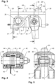
- the Fig. 1 shows, as a non-claimed example, a contact unit carrier 10 as is known from the prior art.
- the contact unit carrier 10 is a component of a contact device not shown in detail here and is attached to a positioning device of the Contact device is arranged so that the contact unit carrier 10 is movable relative to a charging contact device, which is also not shown here, and can be contacted with it.
- the contact unit carrier 10 is formed from a body 11 with contact units 12, 13 and guide elements 14 for attachment to a transverse guide of the positioning device.
- the contact units 12 and 13 each have a contact element 15, contact element guides 16 and 17 respectively, and connecting lines 18.
- the connecting lines are formed from conductors 19 with cable lugs 20, wherein the cable lugs 20 are screwed to the contact element guide 16 and 17 respectively to establish an electrical connection contact.
- the contact elements 15 are movable in the direction of their longitudinal axis 21 in the contact element guide 16, project beyond a surface 22 of the housing 11 and are subjected to a spring force.
- a contact end 23 is contacted with a charging contact of the charging contact device, whereby the contact element 15 is then pushed a short distance into the contact element guide 16.
- Current is then transmitted from the charging contact to the contact element 15 and from there to the contact element guide 16 or 17, which in turn is connected to the connecting line 18.
- Two connecting lines 18 are attached, in particular, to the contact element guides 17 in order to be able to conduct high currents via the connecting lines 18.
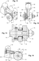
- a summary of the Fig. 2 to 5 shows, as an embodiment of the invention, a contact unit 24 that can be attached to a body of a contact unit carrier (not shown in detail here).
- the contact unit 24 comprises a contact element 25, a pivot bearing 26, and a connecting element 27, which forms a connecting bridge 28.
- the connecting element 27 has bores 30 at its respective ends 29 for connection to the side walls (not shown here).
- the contact element 25 is formed from a lever arm 31 and a bolt-shaped contact bump 32.
- the contact bump 32 is pivotally mounted on the pivot bearing 26 in the direction of its longitudinal axis 33 and can contact a charging contact of a charging contact device (not shown here) with a surface 34 on a contact end 35 of the contact bump 32.
- the lever arm 31 has a through-opening 36 into which a screw 37 is inserted for clamping cable lugs 38 of connecting lines (not shown here) to the contact element 25. Furthermore, a through-opening 39 is formed in the connecting element 27, into which an axle 40 of the pivot bearing 26 is inserted and fastened by screwing.
- the lever arm 31 here also has a through-opening 42 at an end 41 facing away from the contact bump 32, as well as a groove 43 running transversely to the through-opening 42. Bearing shells 44 and 45 are arranged on the axle 40 in such a way that the lever arm 31 or the contact element 25 can pivot on the pivot bearing 26 with as little play as possible.
- a spring 46 of the contact unit 24 is arranged within the groove 43 surrounding the axis 40, wherein one spring end 47 rests on the connecting element 27 and another spring end 48, as indicated here, rests on the lever arm 31 within the groove 43, thus causing a spring force on the lever arm 31 by prestressing the spring 46.
- a through-opening 50 for the contact bump 32 is formed in an upper surface 49, so that the contact bump 32 projects beyond the upper surface 49.
- a lower surface 51 of the connecting element 27 in the region of the through-opening 50 serves as a stop 52 for limiting the upper end position 53 of the contact element 25 shown here.
- a summary of the Fig. 6 to 10 shows, as an embodiment of the invention, a contact unit 54 with contact elements 55 and 56, pivot bearings 57 and 58 and a connecting element 59.
- the pivot bearing 57 or 58 is formed on the connecting element 59 by means of a screw 60, wherein the screw 60 forms an axis 63 of the pivot bearing 57 or 58.
- An electrical resistance heating element 64 for heating the pivot bearing 57 or 58 is inserted into the axis 63.
- the axis 63 is surrounded by a spring 65.
- the contact elements 55 and 56 each have a bolt-shaped contact bump 66 or 67 and lever arms 68 or 69, which are fastened to the pivot bearings 57 or 58 by means of the screws 60.
- a cable lug 70 of a connecting cable (not shown here) is directly fastened to the contact element 55 and a stranded wire strip 71 is directly fastened to the contact element 56. Furthermore, the connecting element 59 can be fastened at ends 72 to side walls (not shown in detail here) of a body of a contact device.
- a summary of the Fig. 11 to 14 shows, as an embodiment of the invention, a contact unit 73 which is formed from a contact element 74, a pivot bearing 75 and a connecting element 76.
- the connecting element 76 can be fastened here at one end 77 to a side wall (not shown here) of a body of a contact unit carrier or a contact device.
- a through-opening 78 is formed in the connecting element 76, into which an axle 79 of the pivot bearing 75 is inserted and screwed.
- a bearing shell 80 and a spring 81 are arranged on the axle 79.
- the contact element 74 is formed in two parts from a bolt-shaped contact bump 82 and a lever arm 83, which are screwed together.
- a through-opening 84 is also formed in the lever arm 83, and the lever arm 83 is plugged onto the bearing shell 80 with the through-opening 84.
- the bolt-shaped contact bump 82 is thus around the pivot bearing 75 in the direction of its longitudinal axis 85 pivotable.
- the spring 81 rests with one spring end 86 on the lever arm 83 or is attached thereto, with another spring end 87 resting on a bolt 88 of the axle 79. By preloading the spring 81, a spring force can be exerted on the lever arm 83 and thus in the direction of the longitudinal axis 85.
Landscapes
- Engineering & Computer Science (AREA)
- Power Engineering (AREA)
- Transportation (AREA)
- Mechanical Engineering (AREA)
- Electric Propulsion And Braking For Vehicles (AREA)
- Charge And Discharge Circuits For Batteries Or The Like (AREA)
- Current-Collector Devices For Electrically Propelled Vehicles (AREA)
Description
- Die Erfindung betrifft eine Kontaktvorrichtung für ein Schnellladesystem für elektrisch angetriebene Fahrzeuge, insbesondere Elektrobusse oder dergleichen, wobei das Schnellladesystem eine Ladekontaktvorrichtung und die Kontaktvorrichtung mit einem Kontakteinheitenträger umfasst, wobei der Kontakteinheitenträger eine Mehrzahl von Kontakteinheiten aufweist, wobei mit der Kontakteinheit ein Ladekontakt der Ladekontaktvorrichtung zur Ausbildung einer Kontaktpaarung kontaktierbar ist, wobei die Kontaktvorrichtung oder die Ladekontaktvorrichtung eine Positioniereinrichtung umfasst, wobei mittels der Positioniereinrichtung der Kontakteinheitenträger relativ zu der Ladekontaktvorrichtung positionierbar ist, derart, dass eine elektrisch leitende Verbindung zwischen einem Fahrzeug und einer stationären Ladestation ausbildbar ist, wobei die Kontakteinheit ein Kontaktelement aufweist, wobei die Kontakteinheit eine Anschlussleitung zur Verbindung mit dem Fahrzeug oder der Ladestation aufweist.
- Derartige Kontakteinheiten sind bereits aus dem Stand der Technik bekannt, und werden regelmäßig als eine Baugruppe einer Kontaktvorrichtung zur Schnellladung elektrisch angetriebener Fahrzeuge an einer Haltestelle beziehungsweise einem Haltepunkt eingesetzt. Im Nahverkehr eingesetzte elektrisch angetriebene Fahrzeuge, wie beispielsweise Busse, können unter anderem über eine Oberleitung kontinuierlich mit elektrischer Energie versorgt werden. Dies setzt jedoch das Vorhandensein beziehungsweise den Unterhalt eines Oberleitungssystems voraus. Um die Vorteile eines elektrischen Antriebs auch ohne ein Oberleitungsnetz nutzen zu können, ist es bekannt, öffentliche Verkehrsmittel mit Batterien oder auch anderen Arten von Energiespeichern auszustatten. Ein Dauerbetrieb des Verkehrsmittels kann dadurch gewährleistet werden, dass während eines Halts des Verkehrsmittels an einer Haltestelle eine Schnellladung der Batterien erfolgt.
- Hier sind aus dem Stand der Technik verschiedene Schnellladesysteme zur Herstellung einer elektrisch leitenden Verbindung zwischen einer stationären Ladestation im Bereich einer Haltestelle und einem Fahrzeug beziehungsweise Elektrobus bekannt. So kann an einem Elektrobus ein sogenannter Stromabnehmer mit einer Schleifleiste auf einem Dach eines Elektrobusses angeordnet sein, wobei im Bereich der Haltestelle eine in Fahrtrichtung des Elektrobusses längs verlaufende Schiene über einer Fahrbahn aufgehängt ist. Bei einem Halt des Elektrobusses an der Haltestelle wird der Stromabnehmer von dem Dach des Busses nach oben an die Schiene bewegt, wodurch eine elektrische Verbindung für die Dauer des vorgesehenen Halts des Elektrobusses an der Haltestelle hergestellt wird, sodass in diesem Zeitraum eine Schnellladung erfolgen kann. Insbesondere sind jedoch zwei voneinander unabhängige Stromabnehmer und entsprechende Kontaktierbereiche an der Schiene erforderlich, um einen Ladestromkreis ausbilden zu können.
- Weiter können Kontaktelemente für beispielsweise eine Steuerleitung, Erdung oder eine Datenübertragung erforderlich sein. Es werden dann an einer Kontaktvorrichtung eines Stromabnehmers beziehungsweise Schnellladesystems mehrere Kontaktelemente angeordnet, die mit einer entsprechenden Anzahl in Fahrtrichtung des Elektrobusses angeordneter Ladekontaktelemente, die beispielsweise aus parallelen Schienen ausgebildet sein können, kontaktiert werden können. Eine größere Anzahl von Kontaktpaarungen kann somit hergestellt werden.
- Aus der
WO 2015/01887 A1 - Die
US 2014/0070767 A1 offenbart ein Schnelladesystem für elektrisch angetriebene Fahrzeuge, das eine fahrzeugseitig angebrachte Ladekontaktvorrichtung und eine Kontaktvorrichtung mit einem Kontakteinheitenträger umfasst. - Aus der
DE 20 2015 100 623 U1 ist eine Kontaktvorrichtung für ein Schnelladesystem für elektrisch angetriebene Fahrzeuge bekannt. Die Kontaktvorrichtung weist einen Kontakteinheitsträger mit einer Kontakteinheit auf, die ein Schleifstück umfasst. - Die
WO 2015/018887 A1 zeigt eine Kontakteinheit mit den Merkmalen des Oberbegriffs des Anspruchs 1. Insbesondere ist hier ein Kontaktelement mit einem bolzenförmigen Kontakthöcker ausgebildet, der eine Kontaktfläche zur Kontaktierung eines Ladekontakts ausbildet. - Die
US 5,495,159 A betrifft eine sogenannte Ladevorrichtung für ein fahrerloses Flurförderfahrzeug. Die Ladevorrichtung weist zumindest zwei Kontaktelemente auf, die an einem Schenkel eines Hebels montiert sind, wobei der Hebel um eine Achse schwenkbar gelagert ist. Eine elektrische Kontaktierung erfolgt über eine Schiene mit einem Kabel. - Die Kontaktelemente sind jeweils Teil einer Kontakteinheit, die an dem Kontakteinheitenträger fest montiert ist. Jede Kontakteinheit umfasst eine Kontaktelementführung innerhalb der das jeweilige Kontaktelement in Richtung seiner Längsachse relativ zum Kontakteinheitenträger bewegbar und federnd gelagert ist. Somit wird es möglich, einen eventuellen Winkelversatz beim Zusammenführen von Kontakteinheitenträger und Ladekontaktvorrichtung oder auch eine Neigung eines Busses an einer Haltestelle in Folge einer veränderten Zuladung oder einer Absenkung des Busses auszugleichen und stets eine sicherere Kontaktierung zur Verfügung zu stellen. Die jeweiligen Kontakteinheiten sind über jeweils eine oder mehrere Anschlussleitungen mit dem Fahrzeug verbunden. Insbesondere sind die Anschlussleitungen mittels Kabelschuhen mit der Kontaktelementführung verschraubt. Eine Stromübertragung erfolgt daher von beispielsweise einer elektrisch leitenden Schiene der Ladekontaktvorrichtung auf ein Kontaktelement und von diesem über einen Spalt, der eine Bewegung des Kontaktelements in der Kontaktelementführung erlaubt, auf die Kontaktelementführung, an die die Anschlussleitung geklemmt ist.
- Zur Herstellung einer sicheren Stromübertragung von dem Kontaktelement auf die Kontaktelementführung wird Kontaktfett und eine Kontaktlamelle beziehungsweise ein Lamellenring verwendet. Nachteilig ist hier, dass der Kontakteinheitenträger Umwelteinflüssen, wie Schnee oder Regen sowie auch Dreck und Staub ausgesetzt ist, welcher am Kontaktelement beziehungsweise in den Spalt am Kontaktelement trotz Verwendung einer Ringdichtung eindringen kann. Dies kann in speziellen Fällen dazu führen, dass das Kontaktelement in der Kontaktelementführung blockiert beziehungsweise klemmt und so keine Kontaktierung oder auch eine undefinierte Kontaktierungsreihenfolge mit der Gefahr einer Ausbildung eines Lichtbogens möglich ist. Um ein Versagen bei kalter Witterung zu verhindern, kann es auch vorgesehen sein, eine Heizpatrone an der Kontaktelementführung anzuordnen. Weiter ist es bekannt, Kontaktelemente zu versilbern, um einen Übergangswiderstand im Bereich der Kontaktelementführung günstig zu beeinflussen. Sofern eine Kontakteinheit ausfällt, werden die übrigen Kontakteinheiten mit hohen Strömen durchflossen, was zu einer übermäßigen Erwärmung und zu einem Versagen des gesamten Schnellladesystems führen kann. Die Kontakteinheiten müssen daher in regelmäßigen Abständen ausgetauscht oder gewartet werden, damit eine verlässliche Kontaktierung sichergestellt werden kann.
- Der vorliegenden Erfindung liegt daher die Aufgabe zugrunde, eine Kontakteinheit, eine Kontaktvorrichtung mit einer Kontakteinheit sowie ein Schnellladesystem vorzuschlagen, die beziehungsweise das einen kostengünstigen Betrieb des Verkehrsmittels und eine sichere Kontaktierung ermöglicht.
- Diese Aufgabe wird durch eine Kontaktvorrichtung mit den Merkmalen des Anspruchs 1 und ein Schnellladesystem mit den Merkmalen des Anspruchs 18 gelöst.
- Die Erfindung ist durch die Ansprüche definiert.
- Bei der erfindungsgemäßen Kontaktvorrichtung für ein Schnellladesystem für elektrisch angetriebene Fahrzeuge, insbesondere Elektrobusse oder dergleichen, wobei das Schnellladesystem eine Ladekontaktvorrichtung und die Kontaktvorrichtung mit einem Kontakteinheitenträger umfasst, weist der Kontakteinheitenträger eine Mehrzahl von Kontakteinheiten auf, wobei mit der Kontakteinheit ein Ladekontakt der Ladekontaktvorrichtung zur Ausbildung einer Kontaktpaarung kontaktierbar ist, wobei die Kontaktvorrichtung oder die Ladekontaktvorrichtung eine Positioniereinrichtung umfasst, wobei mittels der Positioniereinrichtung der Kontakteinheitenträger relativ zu der Ladekontaktvorrichtung positionierbar ist, derart, dass eine elektrisch leitende Verbindung zwischen einem Fahrzeug und einer stationären Ladestation ausbildbar ist, wobei die Kontakteinheit ein Kontaktelement aufweist, wobei die Kontakteinheit eine Anschlussleitung zur Verbindung mit dem Fahrzeug oder der Ladestation aufweist, wobei das Kontaktelement an einem Drehlager der Kontakteinheit relativ zum Kontakteinheitenträger schwenkbar gehaltert ist, und dass das Kontaktelement aus einem mit dem Drehlager verbundenen Hebelarm mit einem bolzenförmigen Kontakthöcker ausgebildet ist, wobei der bolzenförmige Kontakthöcker eine Kontaktfläche zur Kontaktierung des Ladekontaktes ausbildet und in Richtung seiner Längsachse an dem Drehlager so schwenkbar ist, dass die Längsachse quer zu dem Drehlager angeordnet ist, und die Längsachse so in Art einer Tangente eines Schwenkradius des Drehlagers angeordnet ist, dass der Kontakthöcker bei der Kontaktierung mit einem Ladekontakt um das Drehlager herum verschwenkt wird, , wobei die Kontakteinheit ein Verbindungselement umfasst, mit dem das Kontaktelement an dem Kontakteinheitenträger angeordnet ist, wobei das Kontaktelement über das Drehlager mit dem Verbindungselement verbunden ist.
- Dadurch, dass das Kontaktelement an dem Drehlager der Kontakteinheit relativ zum Kontakteinheitenträger schwenkbar gelagert ist, wird es möglich eine Bewegbarkeit des Kontaktelements mit einfachen Mitteln sicherzustellen. Die Gefahr eines Klemmens des Kontaktelements an dem Drehlager ist im Vergleich zu den aus dem Stand der Technik bekannten Kontaktelementführungen wesentlich geringer. Darüber hinaus ist ein Drehlager besonders einfach herzustellen und kann leicht gegen Umwelteinflüsse geschützt werden. Insgesamt können so Wartungsintervalle zur Prüfung und gegebenenfalls Austausch der Kontakteinheit wesentlich verlängert werden, wodurch das Verkehrsmittel kostengünstiger betrieben werden kann. Weiter ist eine Wahrscheinlichkeit eines Blockierens des Kontaktelements dann auch sehr gering, sodass das Schnellladesystem sicherer betrieben werden kann.
- Das Kontaktelement ist aus einem mit dem Drehlager verbundenen Hebearm mit einem bolzenförmigen Kontakthöcker ausgebildet, wobei der bolzenförmige Kontakthöcker eine Kontaktfläche zur Kontaktierung des Ladekontakts ausbildet und in Richtung seiner Längsachse an dem Drehlager schwenkbar ist. Das Kontaktelement ist so besonders einfach herstellbar und es kann beispielsweise ein punktueller Kontakt mit einem Ladekontakt einer Ladekontaktvorrichtung ausgebildet werden.
- Es ist vorteilhaft, wenn das bolzenförmige Kontaktelement an seinem Kontaktende mit gerundeten Kanten oder vollständig abgerundet ausgebildet ist. Das Kontaktelement kann dann an einem Ladekontakt entlang bewegt werden, ohne dass es zu einer größeren mechanischen Beschädigung des Ladekontakts oder des Kontaktelements kommt. Alternativ kann das Kontaktelement auch mit einer anderen geeigneten Gestalt ausgebildet sein. Wenn der bolzenförmige Kontakthöcker in Richtung seiner Längsachse an dem Drehlager schwenkbar ist, verläuft die Längsachse stets quer, vorzugsweise in einem Winkel von 90° relativ zu dem Drehlager. Der bolzenförmige Kontakthöcker kann dann so ausgebildet sein, dass die Längsachse in Art einer Tangente eines Schwenkradius des Drehlagers angeordnet ist. Der Hebelarm verbindet dann den Kontakthöcker mit dem Drehlager. Weiter kann das Kontaktelement aus Kupfer bzw. einer Kupferlegierung bestehen und/oder unversilbert sein. Kupfer eignet sich besonders gut zur Verwendung für elektrisch leitende Bauteile, wobei die Anschlussleitung ebenfalls aus Kupfer bestehen kann. Insbesondere Kupferlegierungen weisen eine vergleichsweise hohe Verschleißfestigkeit und Anlaufbeständigkeit auf. Da keine Stromübertragung von einer Oberfläche des Kontaktelements auf das Drehlager erfolgen muss, kann auf ein Versilbern des Kontaktelements vollständig verzichtet werden, was die Herstellungskosten für das Kontaktelement wesentlich herabsetzt.
- Auch kann das Kontaktelement einstückig oder mehrteilig ausgebildet sein. So kann dann das Kontaktelement aus verschiedenen Materialien, die jeweils für ihren Einsatzzweck geeignet sind, hergestellt werden. Gleichwohl ist es möglich das Kontaktelement einstückig und damit einfach montierbar auszubilden.
- Die Anschlussleitung kann unmittelbar an dem Kontaktelement befestigt sein. Es muss dann nicht mehr, wie bei aus dem Stand der Technik bekannten Kontaktelementen mit einer Kontaktelementführung, ein Spalt zwischen der Kontaktelementführung und dem Kontaktelement zur Übertragung von Strömen genutzt werden. Auch kann dann die Anschlussleitung zusammen mit dem Kontaktelement bewegt werden. Weiter sind leitende Fette, oder andere Bauteile zur Begünstigung einer Stromübertragung im Bereich einer Kontaktelementführung bzw. des Drehlagers nicht mehr erforderlich. Ein Übergangswiderstand zwischen der Anschlussleitung und dem Kontaktelement kann so wesentlich verringert werden.
- Die Anschlussleitung kann einen Leiterquerschnitt von zumindest 50 mm2, vorzugsweise 95 mm2 aufweisen. So wird es möglich, mit der Kontakteinheit besonders hohe Ströme zu übertragen. Bei den aus dem Stand der Technik bekannten Kontakteinheiten sind mehrere Anschlussleitungen über Kabelschuhe an einer Kontaktelementführung angeschraubt. Wenn die Anschlussleitung unmittelbar an dem Kontaktelement befestigt ist, können auch höhere Ströme über die Anschlussleitung übertragen werden, weshalb ein derartig großer Leiterquerschnitt ausgewählt werden kann. Eine unerwünschte Erwärmung des Anschlussleiters kann so verhindert werden. Eine Querschnittsform des Anschlussleiters ist prinzipiell beliebig, weshalb der Anschlussleiter beispielsweise auch ein Litzenband sein kann. Prinzipiell kann die Anschlussleitung jedoch mit jedem beliebigen Leiterquerschnitt ausgebildet sein.
- Das Drehlager kann an einer Achse des Drehlagers eine Lagerbuchse aus einem dielektrischen Material aufweisen. Prinzipiell ist das Material der Lagerbuchse beliebig auswählbar, wobei die Lagerbuchse dann auch aus Aluminium, einem Kunststoffmaterial oder einem anderen dielektrischen Material bestehen kann. Dies wird möglich, da mit einer übermäßigen Erwärmung der Kontakteinheit im Bereich des Drehlagers infolge eines Übergangswiderstands nicht mehr zu rechnen ist, wenn eine Anschlussleitung unmittelbar an dem Kontaktelement befestigt ist. Eine Lagerbuchse kann beispielsweise aus einem Material mit guten Gleit- oder Dichtungseigenschaften bestehen, beispielsweise PTFE. Die Achse des Drehlagers kann besonders einfach aus einem Bolzen oder einer Schraube ausgebildet werden. Durch die Verwendung einer Lagerbuchse aus dielektrischem Material wird es auch möglich das Kontaktelement von den übrigen Bauteilen der Kontakteinheit elektrisch zu trennen.
- Eine Feder der Kontakteinheit kann eine Federkraft auf das Kontaktelement bewirken, derart, dass das Kontaktelement in Richtung zu einem Ladekontakt gedrückt wird. Eine federnde Lagerung des Kontaktelements kann durch eine Druckfeder, insbesondere Spiralfeder, an dem Kontaktelement beziehungsweise im Bereich des Drehlagers ausgeführt werden. Infolge dessen kann so ein punktueller Kontakt mit einem Ladekontakt unter einer Federvorspannung ausgebildet werden. Eine Federkraft kann so gewählt werden, dass das Kontaktelement stets in Richtung zu dem Ladekontakt gedrückt und in eine vordere Endlage bewegt wird, wenn das Kontaktelement nicht mit einem Ladekontakt kontaktiert ist.
- Die Feder kann eine gewundene Torsionsfeder sein, die an einer Achse des Drehlagers gehaltert sein kann. Die Torsionsfeder kann in Art einer Schraubenfeder um die Achse des Drehlagers gewickelt sein. Jeweilige Enden der Feder können in radialer Richtung freistehend ausgebildet sein, sodass die Enden der Feder relativ zueinander um die Achse unter Ausbildung einer Federkraft verschwenkt werden können. Ein Ende der Torsionsfeder kann an dem Kontaktelement angelegt oder fixiert sein, wobei ein anderes Ende der Torsionsfeder an dem Drehlager oder einem weiteren Bauteil der Kontakteinheit, beispielsweise einem Verbindungselement, festgelegt sein kann. So wird es einfach möglich das Kontaktelement an dem Drehlager mittels der so ausgebildeten Federkraft in eine Endlage zu Schwenken.
- Das Drehlager kann ein elektrisches Widerstandsheizelement aufweisen. Das elektrische Widerstandsheizelement kann beispielsweise in Art einer Heizbuchse oder Heizpatrone ausgebildet sein. Eine Heizpatrone kann einfach in eine Bohrung innerhalb einer Achse des Drehlagers oder in eine Bohrung innerhalb eines Lagergehäuses des Drehlagers eingesetzt werden. So wird es möglich auch bei tiefen Temperaturen ein Einfrieren des Drehlagers wirkungsvoll zu verhindern.
- Erfindungsgemäß umfasst die Kontakteinheit ein Verbindungselement, mit dem das Kontaktelement an dem Kontakteinheitenträger anordbar ist, wobei das Kontaktelement über das Drehlager mit dem Verbindungselement verbunden ist. Demnach ist das Drehlager mit dem Verbindungselement an dem Kontakteinheitenträger so befestigt, dass das Kontaktelement an dem Kontakteinheitenträger schwenkbar ist. In einer besonders einfachen Ausführungsform kann das Verbindungselement mittels einer Schraubenverbindung an dem Kontakteinheitenträger befestigbar sein und eine Achse ausbilden, auf die das Kontaktelement einfach aufgesteckt werden kann. Die Achse kann auch eine Schraube sein, die in einer Bohrung oder Durchgangsöffnung in dem Verbindungselement eingesetzt ist.
- Das Verbindungselement kann auch einen Anschlag aufweisen, der eine Schwenkbewegung des Kontaktelements relativ zu dem Kontakteinheitenträger begrenzt. Der Anschlag kann beispielsweise ein abgesetzter Durchmesser an dem Drehlager oder ein Absatz an dem Verbindungselement sein, an dem das Kontaktelement zur Anlage gelangen kann. Der Anschlag kann auch einfach durch einen Bolzen ausgebildet sein, der an dem Verbindungselement oder dem Kontaktelement befestigt ist. Mittels des Anschlages kann eine Schwenkbewegung des Kontaktelements in Richtung zu einem Ladekontakt und/oder in eine entgegengesetzte Richtung begrenzt sein. So kann dann auch eine definierte vordere Endlage und hintere Endlage des Kontaktelements an dem Drehlager begrenzt werden.
- In einer vorteilhaften Ausführungsform kann das Verbindungselement eine Verbindungsbrücke ausbilden, mittels der zwei parallele Seitenwände des Kontakteinheitenträgers verbindbar sind. Das Verbindungselement kann dann nicht nur zur Halterung des Kontaktelements dienen, sondern auch als ein Bauteil des Kontakteinheitenträgers, dessen Seitenwände verbinden. Beispielsweise kann das Verbindungselement dann auch in Art eines verbindenden Längsprofils ausgebildet sein, das an seinen gegenüberliegenden Enden mittels Stift- und/oder Schraubverbindungen an die Seitenwände angeschlossen ist. Eine Achse des Drehlagers kann relativ zu den Seitenwänden parallel oder orthogonal an dem Verbindungselement beziehungsweise der Verbindungsbrücke angeordnet sein.
- Weiter kann die Kontakteinheit zwei Kontaktelemente aufweisen, die jeweils an einem Drehlager relativ zum Kontakteinheitenträger schwenkbar gehaltert sind, wobei das Verbindungselement dann beide Kontaktelemente haltern kann. Das Verbindungselement kann dann so ausgestaltet sein, dass zwei Drehlager an dem Verbindungselement angeordnet oder ausgebildet sind, wobei die Drehlager relativ zueinander parallel angeordnet sein können. Es ist dann auch möglich den Aufbau eines Kontakteinheitenträgers wesentlich zu vereinfachen. Dabei kann auch vorgesehen sein, die jeweiligen Kontaktelemente über die Drehlager elektrisch voneinander zu entkoppeln, wobei das Verbindungselement selbst auch aus einem dielektrischen Werkstoff ausgebildet sein kann. Dies wird insbesondere möglich, wenn die jeweilige Anschlussleitung unmittelbar an dem zugehörigen Kontaktelement angeordnet ist.
- Die Drehlager können relativ zueinander quer an dem Verbindungselement angeordnet sein. Dadurch wird es möglich die Kontakteinheit besonders kompakt auszubilden. Insbesondere können die Drehlager relativ zueinander orthogonal angeordnet sein.
- Die Kontakteinheit kann so ausgebildet sein, dass über die Kontakteinheit ein Strom von 500 A bis 1.000 A, vorzugsweise von 800 A bei einer Spannung von 750 V übertragbar ist. Folglich ist eine Leistung von 375 kW bis 750 kW, vorzugsweise von 600 kW über die Kontakteinheit übertragbar. Es kann daher dann auch ausreichend sein lediglich eine Anschlussleitung zur Verbindung mit dem Kontaktelement vorzusehen. Auch kann eine schnellere Ladung des Fahrzeugs erfolgen, da höhere Ströme in kürzerer Zeit übertragen werden können. Gegebenenfalls kann auch an einem Kontakteinheitenträger eine Anzahl der Kontakteinheiten vermindert werden, wodurch die Kontaktvorrichtung kostengünstiger herstellbar wird.
- Die Kontaktvorrichtung weist eine Mehrzahl von Kontakteinheiten, beispielsweise für unterschiedliche Phasen, eine Erdung oder eine Datenübertragung auf.
- Die Positioniereinrichtung kann einen Pantografen oder eine Schwinge aufweisen, mittels dem beziehungsweise der der Kontakteinheitenträger in zumindest vertikaler Richtung zur Ladekontakteinheit positioniert werden kann, wobei die Kontaktvorrichtung an einem Fahrzeug oder an einer Ladestation angeordnet werden kann. Bei einer Schwinge kann ein ergänzendes Koppelgetriebe vorgesehen sein, welches den Kontakteinheitenträger relativ zu einer Ladekontaktvorrichtung stabilisiert beziehungsweise in der betreffenden Richtung ausrichtet. Ein Pantograf oder eine Schwinge beziehungsweise ein entsprechender mechanischer Antrieb ist besonders einfach und kostengünstig herstellbar. Ergänzend kann die Positioniereinrichtung auch eine Querführung aufweisen, mittels der der Kontakteinheitenträger quer relativ zur Ladekontaktvorrichtung beziehungsweise zu einer Fahrtrichtung des Fahrzeugs positioniert werden kann. Die Querführung kann an einem Fahrzeug oder einem Pantografen oder einer Schwinge der Positioniereinrichtung angeordnet sein. In beiden Fällen ist dann die Positioniereinrichtung beziehungsweise ein an der Positioniereinrichtung angeordneter Kontakteinheitenträger quer zur Fahrtrichtung des Fahrzeugs verschiebbar. Durch diese Verschiebbarkeit kann beispielsweise eine fehlerhafte Positionierung des Fahrzeugs an einer Haltestelle quer zur Fahrtrichtung ausgeglichen werden. Darüber hinaus können eventuelle Fahrzeugbewegungen in Folge eines einseitigen Absenkens des Fahrzeugs zum Ein- und Aussteigen von Personen so ausgeglichen werden, dass es zu keiner Verschiebung des Kontakteinheitenträgers relativ zur Ladekontaktvorrichtung in Querrichtung kommen kann. Die Kontaktvorrichtung kann beispielsweise auf einem Fahrzeugdach angeordnet sein, sodass der Kontakteinheitenträger von dem Fahrzeugdach ausgehend mittels der Positioniereinrichtung zu der Ladekontaktvorrichtung und zurück bewegt werden kann. Alternativ kann die Kontaktvorrichtung an der Ladestation angeordnet sein, wobei der Kontakteinheitenträger dann von einem Träger, wie beispielsweise einem Mast oder einer Brücke, an einer Haltestelle in Richtung auf ein Fahrzeugdach mit einer Ladekontaktvorrichtung und zurück bewegt werden kann.
- Zumindest zwei Kontaktelemente können relativ zu einer der Ladekontakteinheit zugewandten Oberfläche des Kontakteinheitenträgers in unterschiedlichen Höhen hervorstehen. So ist es dann möglich, bei der Ausbildung von zumindest zwei Kontaktpaarungen zwischen jeweils einem Kontaktelement und einem Ladekontakt eine definierte Reihenfolge bei der Herstellung der Kontaktpaarungen sicher zu stellen. Bei einem Zusammenführen von Kontakteinheitenträger und Ladekontaktvorrichtung wird dann eine Kontaktreihenfolge zwangsläufig immer eingehalten und aufgrund der geometrischen Anordnung der Kontaktelemente relativ zu der Oberfläche des Kontakteinheitenträgers sichergestellt. Eine unbeabsichtigte oder fehlerhafte Kontaktierung beziehungsweise Ausbildung von Kontaktpaarungen kann so leicht verhindert werden.
- Der Kontakteinheitenträger kann einen Korpus aufweisen, der mit Durchgangsöffnungen ausgebildet ist. Demnach kann der Korpus offen, das heißt von Luft durchströmbar, ausgebildet sein. Wenn der Korpus eine Reihe von Durchgangsöffnungen aufweist, können die an dem Korpus angeordneten Kontaktelemente auch einfach mittels Luft gekühlt werden, sodass eine unerwünschte Erwärmung der Kontaktelemente infolge einer Stromübertragung bei einem Ladevorgang mit einfachen Mitteln reduziert werden kann. Darüber hinaus kann der Korpus, und damit der Kontakteinheitenträger, mit einem geringeren Gewicht ausgebildet werden.
- Der Korpus kann aus zwei parallelen Seitenwänden aus einem dielektrischen Material ausgebildet sein, wobei die Seitenwände mittels Verbindungsbrücken miteinander verbunden sein können.
- Der Korpus kann beispielsweise aus einem Kunststoffmaterial ausgebildet sein, wobei die parallelen Seitenwände auch aus einem faserverstärkten Kunststoffmaterial ausgebildet sein können. Die Seitenwände sind so besonders einfach, stabil und kostengünstig herstellbar. Der Korpus kann dadurch ausgebildet werden, dass die Seitenwände mittels der Verbindungsbrücken verbunden sind. Die Verbindungsbrücken legen dann einen Relativabstand der Seitenwände fest und können beispielsweise mit den Seitenwänden verschraubt sein. Die Verbindungsbrücken können ebenfalls aus einem Kunststoffmaterial oder auch aus einem Metall bestehen und als ein einfacher, rechteckiger Streifen ausgebildet sein. Innerhalb der Verbindungsbrücken können Durchgangsöffnungen ausgebildet sein, in die dann jeweils eine Kontakteinheit nach Bedarf eingesetzt und befestigt ist. Eine besondere elektrische Isolierung der Kontakteinheiten oder der Verbindungsbrücken ist nicht erforderlich, wenn die Seitenwände aus dem dielektrischen Material ausgebildet sind.
- Weitere vorteilhafte Ausführungsformen einer Kontaktvorrichtung ergeben sich aus den auf den Anspruch 1 rückbezogenen Unteransprüchen.
- Das erfindungsgemäße Schnellladesystem weist eine Ladekontaktvorrichtung und eine erfindungsgemäße Kontaktvorrichtung auf.
- Die Ladekontaktvorrichtung kann eine Aufnahmeöffnung für den Kontakteinheitenträger ausbilden, wobei der Kontakteinheitenträger in die Aufnahmeöffnung der Ladekontaktvorrichtung einsetzbar sein kann. Dabei kann die Aufnahmeöffnung vorzugsweise V-förmig ausgebildet sein. Bei einer Relativabweichung des Kontakteinheitenträgers bei einem Zusammenführen von Kontakteinheitenträger und Ladekontaktvorrichtung zur Aufnahmeöffnung bewirkt dann die V-förmige Ausbildung der Aufnahmeöffnung eine Zentrierung des Kontakteinheitenträgers. Die Aufnahmeöffnung bildet daher eine Führung für den Kontakteinheitenträger aus, die eine Abweichung von einer Kontaktposition an der Ladekontaktvorrichtung ausgleichen kann.
- Der Kontakteinheitenträger kann alternativ eine Aufnahmeöffnung für die Ladekontaktvorrichtung ausbilden, wobei die Ladekontaktvorrichtung in die Aufnahmeöffnung des Kontakteinheitenträgers einsetzbar sein kann. Die Aufnahmeöffnung kann dann ebenfalls vorzugsweise V-förmig ausgebildet sein. Die Aufnahmeöffnung bildet dann auch eine Führung für die Ladekontaktvorrichtung aus.
- Die Ladekontaktvorrichtung und/oder eine Querführung der Positioniervorrichtung kann ein elektrisches Widerstandsheizelement aufweisen. So kann dann beispielsweise eine Ablagerung von Reif, Eis oder Schnee an der Ladekontaktvorrichtung durch Erwärmen der Ladekontaktvorrichtung mittels des elektrischen Widerstandsheizelements verhindert werden. Auch kann die Querführung der Positioniervorrichtung mit dem elektrischen Widerstandsheizelement beheizt werden, sodass dann stets sichergestellt ist, dass die Querführung auch bei niedrigen Temperaturen bewegbar ist und nicht einfrieren kann.
- Vorteilhafte Ausführungsformen des Schnellladesystems ergeben sich aus den auf den Anspruch 1 rückbezogenen Unteransprüchen.
- Die Erfindung ist prinzipiell für jede Art von Elektrofahrzeug nutzbar, welches mit Batterien betrieben wird, die nachgeladen werden müssen.
- Nachfolgend werden ein Erklärungsbeispiel und bevorzugte Ausführungsformen der Erfindung unter Bezugnahme auf die beigefügten Zeichnungen näher erläutert.
- Es zeigen:
- Fig. 1
- einen Kontakteinheitenträger nach dem Stand der Technik in einer Seitenansicht;
- Fig. 2
- eine erste Ausführungsform einer Kontakteinheit in einer perspektivischen Ansicht;
- Fig. 3
- eine Seitenansicht der Kontakteinheit aus
Fig. 2 ; - Fig. 4
- eine Schnittansicht entlang einer Linie IV - IV aus
Fig. 3 ; - Fig. 5
- eine Schnittansicht entlang einer Linie V - V aus
Fig. 3 ; - Fig. 6
- eine zweite Ausführungsform einer Kontakteinheit in einer perspektivischen Ansicht;
- Fig. 7
- die Kontakteinheit aus
Fig. 6 in einer Seitenansicht; - Fig. 8
- die Kontakteinheit aus
Fig. 6 in einer Rückansicht; - Fig. 9
- die Kontakteinheit aus
Fig. 6 in einer Unteransicht; - Fig. 10
- eine Schnittansicht entlang einer Linie X - X aus
Fig. 9 ; - Fig. 11
- eine dritte Ausführungsform einer Kontakteinheit in einer perspektivischen Ansicht;
- Fig. 12
- die Kontakteinheit aus
Fig. 11 in einer Draufsicht; - Fig. 13
- eine Schnittansicht entlang einer Linie XIII - XIII aus
Fig. 12 ; - Fig. 14
- die Kontakteinheit aus
Fig. 11 in einer Seitenansicht. - Die
Fig. 1 zeigt als ein nicht beanspruchtes Beispiel einen Kontakteinheitenträger 10, wie er aus dem Stand der Technik bekannt ist. Der Kontakteinheitenträger 10 ist Bestandteil einer hier nicht näher dargestellten Kontaktvorrichtung und an einer Positioniereinrichtung der Kontaktvorrichtung angeordnet, sodass der Kontakteinheitenträger 10 relativ zu einer Ladekontaktvorrichtung, die hier ebenfalls nicht dargestellt ist, bewegbar und mit dieser kontaktierbar ist. Der Kontakteinheitenträger 10 ist aus einem Korpus 11 mit Kontakteinheiten 12, 13 und Führungselementen 14 zur Befestigung an einer Querführung der Positioniereinrichtung ausgebildet. Die Kontakteinheiten 12 und 13 weisen jeweils ein Kontaktelement 15, Kontaktelementführungen 16 beziehungsweise 17 und Anschlussleitungen 18 auf. Die Anschlussleitungen sind aus Leitern 19 mit Kabelschuhen 20 ausgebildet, wobei die Kabelschuhe 20 an der Kontaktelementführung 16 beziehungsweise 17 zur Herstellung eines elektrischen Verbindungskontakts verschraubt sind. Die Kontaktelemente 15 sind in Richtung ihrer Längsachse 21 in der Kontaktelementführung 16 bewegbar, überragen eine Oberfläche 22 des Gehäuses 11 und sind mit einer Federkraft beaufschlagt. Zur Ausbildung einer Kontaktpaarung wird ein Kontaktende 23 mit einem Ladekontakt der Ladekontaktvorrichtung kontaktiert, wobei das Kontaktelement 15 dann ein Stück weit in die Kontaktelementführung 16 hinein gedrückt wird. Eine Stromübertragung erfolgt dann von dem Ladekontakt zu dem Kontaktelement 15 und von diesem auf die Kontaktelementführung 16 beziehungsweise 17, die ihrerseits mit der Anschlussleitung 18 verbunden ist. Insbesondere an den Kontaktelementführungen 17 sind zwei Anschlussleitungen 18 befestigt, um hohe Ströme über die Anschlussleitungen 18 leiten zu können. - Eine Zusammenschau der
Fig. 2 bis 5 zeigt als ein Ausführungsbeispiel der Erfindung eine Kontakteinheit 24, die an einem hier nicht näher dargestellten Korpus eines Kontakteinheitenträgers befestigbar ist. Die Kontakteinheit 24 umfasst ein Kontaktelement 25, ein Drehlager 26 und ein Verbindungselement 27, welches eine Verbindungsbrücke 28 ausbildet. Das Verbindungselement 27 weist an seinen jeweiligen Enden 29 Bohrungen 30 zur Verbindung mit den hier nicht dargestellten Seitenwänden auf. Das Kontaktelement 25 ist aus einem Hebelarm 31 und einem bolzenförmigen Kontakthöcker 32 ausgebildet. Der Kontakthöcker 32 ist in Richtung seiner Längsachse 33 an dem Drehlager 26 schwenkbar gelagert und kann mit einer Oberfläche 34 an einem Kontaktende 35 des Kontakthöckers 32 einen hier nicht dargestellten Ladekontakt einer Ladekontaktvorrichtung kontaktieren. - Der Hebelarm 31 weist eine Durchgangsöffnung 36 auf, in die eine Schraube 37 zum Klemmen von Kabelschuhen 38 hier nicht weiter dargestellter Anschlussleitungen an dem Kontaktelement 25 eingesetzt ist. Weiter ist in dem Verbindungselement 27 eine Durchgangsöffnung 39 ausgebildet, in die eine Achse 40 des Drehlagers 26 eingesteckt und durch Verschrauben befestigt ist. Der Hebelarm 31 weist hier an einem den Kontakthöcker 32 abgewandten Ende 41 ebenfalls eine Durchgangsöffnung 42 sowie eine quer zur Durchgangsöffnung 42 verlaufende Nut 43 auf. Auf der Achse 40 sind Lagerschalen 44 und 45 angeordnet, derart, dass der Hebelarm 31 beziehungsweise das Kontaktelement 25 an dem Drehlager 26 weitestgehend spielfrei schwenkbar ist. Die Achse 40 umgebend ist innerhalb der Nut 43 eine Feder 46 der Kontakteinheit 24 angeordnet, wobei ein Federende 47 an dem Verbindungselement 27 und ein weiteres Federende 48, wie hier angedeutet, innerhalb der Nut 43 an dem Hebelarm 31 anliegt, und so eine Federkraft auf den Hebelarm 31 durch eine Vorspannung der Feder 46 bewirkt.
- Innerhalb des Verbindungselements 27 ist in einer oberen Oberfläche 49 eine Durchgangsöffnung 50 für den Kontakthöcker 32 ausgebildet, sodass der Kontakthöcker 32 die obere Oberfläche 49 überragt. Eine untere Oberfläche 51 des Verbindungselements 27 im Bereich der Durchgangsöffnung 50 dient hier als ein Anschlag 52 zur Begrenzung der hier dargestellten oberen Endlage 53 des Kontaktelements 25. Wenn das Kontaktelement 25 beziehungsweise der Kontakthöcker 32 mit einem hier nicht dargestellten Ladekontakt kontaktiert wird, wird der Kontakthöcker 32 in die Durchgangsöffnung 50 entgegen der Federkraft der Feder 46 hineingedrückt und dabei um das Drehlager 26 herum verschwenkt.
- Eine Zusammenschau der
Fig. 6 bis 10 zeigt als ein Ausführungsbeispiel der Erfindung eine Kontakteinheit 54 mit Kontaktelementen 55 und 56, Drehlagern 57 und 58 und einem Verbindungselement 59. An dem Verbindungselement 59 ist mittels jeweils einer Schraube 60 das Drehlager 57 beziehungsweise 58 ausgebildet, wobei die Schraube 60 eine Achse 63 des Drehlagers 57 beziehungsweise 58 ausbildet. In die Achse 63 ist ein elektrisches Widerstandsheizelement 64 zur Beheizung des Drehlagers 57 beziehungsweise 58 eingesteckt. Weiter ist die Achse 63 von einer Feder 65 umgeben. Die Kontaktelemente 55 und 56 weisen jeweils einen bolzenförmigen Kontakthöcker 66 beziehungsweise 67 und Hebelarme 68 beziehungsweise 69 auf, die an den Drehlagern 57 beziehungsweise 58 mittels der Schrauben 60 befestigt sind. An dem Kontaktelement 55 ist ein Kabelschuh 70 einer hier nicht dargestellten Anschlussleitung und an dem Kontaktelement 56 ein Litzenband 71 unmittelbar befestigt. Weiter kann das Verbindungselement 59 an Enden 72 an hier nicht näher dargestellten Seitenwänden eines Korpus einer Kontaktvorrichtung befestigt werden. - Eine Zusammenschau der
Fig. 11 bis 14 zeigt als ein Ausführungsbeispiel der Erfindung eine Kontakteinheit 73, die aus einem Kontaktelement 74, einem Drehlager 75 und einem Verbindungselement 76 ausgebildet ist. Das Verbindungselement 76 ist hier an einem Ende 77 an einer hier nicht dargestellten Seitenwand eines Korpus eines Kontakteinheitenträgers beziehungsweise einer Kontaktvorrichtung befestigbar. In dem Verbindungselement 76 ist eine Durchgangsöffnung 78 ausgebildet, in die eine Achse 79 des Drehlagers 75 eingesteckt und verschraubt ist. Auf der Achse 79 sind eine Lagerschale 80 und eine Feder 81 angeordnet. Das Kontaktelement 74 ist hier zweiteilig aus einem bolzenförmigen Kontakthöcker 82 und einem Hebelarm 83, die miteinander verschraubt sind, ausgebildet. In dem Hebelarm 83 ist ebenfalls eine Durchgangsöffnung 84 ausgebildet, und der Hebelarm 83 ist mit der Durchgangsöffnung 84 auf die Lagerschale 80 aufgesteckt. Der bolzenförmige Kontakthöcker 82 ist so um das Drehlager 75 in Richtung seiner Längsachse 85 schwenkbar. Die Feder 81 liegt mit einem Federende 86 an dem Hebelarm 83 an beziehungsweise ist an diesem befestigt, wobei ein weiteres Federende 87 an einem Bolzen 88 der Achse 79 anliegt. Durch eine Vorspannung der Feder 81 kann so eine Federkraft auf den Hebelarm 83 und damit in Richtung der Längsachse 85 bewirkt werden.
Claims (21)
- Kontaktvorrichtung für ein Schnellladesystem für elektrisch angetriebene Fahrzeuge, insbesondere Elektrobusse oder dergleichen, wobei das Schnelladesystem eine Ladekontaktvorrichtung und die Kontaktvorrichtung mit einem Kontakteinheitenträger (10) umfasst, wobei der Kontakteinheitenträger eine Mehrzahl von Kontakteinheiten (24, 54, 73) aufweist, wobei mit der Kontakteinheit ein Ladekontakt der Ladekontaktvorrichtung zur Ausbildung einer Kontaktpaarung kontaktierbar ist, wobei die Kontaktvorrichtung oder die Ladekontaktvorrichtung eine Positioniereinrichtung umfasst, wobei mittels der Positioniereinrichtung der Kontakteinheitenträger relativ zu der Ladekontaktvorrichtung positionierbar ist, derart, dass eine elektrisch leitende Verbindung zwischen einem Fahrzeug und einer stationären Ladestation ausbildbar ist, wobei die Kontakteinheit (24, 54, 73) ein Kontaktelement (25, 55, 56, 74) aufweist, wobei die Kontakteinheit (24, 54, 73) eine Anschlussleitung (38, 70, 71) zur Verbindung mit dem Fahrzeug oder der Ladestation aufweist, wobei das Kontaktelement (25, 55, 56, 74) an einem Drehlager (26, 57, 58, 75) der Kontakteinheit (24, 54, 73) relativ zum Kontakteinheitenträger schwenkbar gehaltert ist, und dass das Kontaktelement (25, 55, 56, 74) aus einem mit dem Drehlager (26, 57, 58, 75) verbundenen Hebelarm (31, 68, 69, 83) mit einem bolzenförmigen Kontakthöcker (32, 66, 67, 82) ausgebildet ist, wobei der bolzenförmige Kontakthöcker (32, 66, 67, 82) eine Kontaktfläche (34) zur Kontaktierung des Ladekontaktes ausbildet und in Richtung seiner Längsachse (33, 85) an dem Drehlager (26, 57, 58, 75) so schwenkbar ist, dass die Längsachse (33, 85) quer zu dem Drehlager (26, 57, 58, 75) angeordnet ist, und die Längsachse (33, 85) so in Art einer Tangente eines Schwenkradius des Drehlagers (26, 57, 58, 75) angeordnet ist, dass der Kontakthöcker (32, 66, 67, 82) bei der Kontaktierung mit einem Ladekontakt um das Drehlager (26, 57, 58, 75) herum verschwenkt wird, wobei die Kontakteinheit (24, 54, 73) ein Verbindungselement (27, 59, 76) umfasst, mit dem das Kontaktelement (25, 55, 56, 74) an dem Kontakteinheitenträger angeordnet ist, wobei das Kontaktelement (25, 55, 56, 74) über das Drehlager (26, 57, 58, 75) mit dem Verbindungselement 27, 59, 76) verbunden ist.
- Kontaktvorrichtung nach Anspruch 1,
dadurch gekennzeichnet,
dass das Kontaktelement (25, 55, 56, 74) einstückig oder mehrteilig ausgebildet ist. - Kontaktvorrichtung nach Anspruch 1 oder 2,
dadurch gekennzeichnet,
dass die Anschlussleitung (38, 70, 71) unmittelbar an dem Kontaktelement (25, 55, 56, 74) befestigt ist. - Kontaktvorrichtung nach einem der vorangehenden Ansprüche,
dadurch gekennzeichnet,
dass die Anschlussleitung (38, 70, 71) einen Leiterquerschnitt von zumindest 50 mm2, vorzugsweise 95 mm2 aufweist. - Kontaktvorrichtung nach einem der vorangehenden Ansprüche,
dadurch gekennzeichnet,
dass das Drehlager (26, 57, 58, 75) an einer Achse (40, 63, 79) des Drehlagers (26, 57, 58, 75) eine Lagerbuchse (44, 45, 80) aus einem dielektrischen Material aufweist. - Kontaktvorrichtung nach einem der vorangehenden Ansprüche,
dadurch gekennzeichnet,
dass eine Feder (46, 65, 81) der Kontakteinheit (24, 54, 73) eine Federkraft auf das Kontaktelement (25, 55, 56, 74) bewirkt, derart, dass das Kontaktelement (25, 55, 56, 74) in Richtung zu einem Ladekontakt gedrückt wird. - Kontaktvorrichtung nach Anspruch 6,
dadurch gekennzeichnet,
dass die Feder (46, 65, 81) eine gewundene Torsionsfeder ist, die an einer Achse (40, 63, 79) des Drehlagers (26, 57, 58, 75) gehaltert ist. - Kontaktvorrichtung nach einem der vorangehenden Ansprüche,
dadurch gekennzeichnet,
dass das Drehlager (26, 57, 58, 75) ein elektrisches Widerstandsheizelement (64) aufweist. - Kontaktvorrichtung nach einem der vorangehenden Ansprüche,
dadurch gekennzeichnet,
dass das Verbindungselement (27, 59, 76) einen Anschlag (52) aufweist, der eine Schwenkbewegung des Kontaktelements (25, 55, 56, 74) relativ zu dem Kontakteinheitenträger begrenzt. - Kontaktvorrichtung nach einem der vorangehenden Ansprüche,
dadurch gekennzeichnet,
dass das Verbindungselement (27, 59, 76) eine Verbindungsbrücke (28) ausbildet, mittels der zwei parallele Seitenwände des Kontakteinheitenträges verbindbar sind. - Kontaktvorrichtung nach einem der vorangehenden Ansprüche,
dadurch gekennzeichnet,dass die Kontakteinheit (24, 54, 73) zwei Kontaktelemente (25, 55, 56, 74) aufweist, die jeweils an einem Drehlager (26, 57, 58, 75) relativ zum Kontakteinheitenträger schwenkbar gehaltert sind, wobeidas Verbindungselement (27, 59, 76) beide Kontaktelemente (25, 55, 56, 74) haltert. - Kontaktvorrichtung nach einem der vorangehenden Ansprüche,
dadurch gekennzeichnet,
dass die Drehlager (56, 57, 58, 75) relativ zueinander quer an dem Verbindungselement (27, 59, 76) angeordnet sind. - Kontaktvorrichtung nach einem der vorangehenden Ansprüche,
dadurch gekennzeichnet,
dass die Kontakteinheit (24, 54, 73) so ausgebildet ist, dass über die Kontakteinheit (24, 54, 73) ein Strom von 500 A bis 1000 A, vorzugsweise von 800 A bei einer Spannung von 750 V übertragbar ist. - Kontaktvorrichtung nach einem der vorangehenden Ansprüche,
dadurch gekennzeichnet,dass die Positioniereinrichtung einen Pantografen oder eine Schwinge aufweist, mittels dem bzw. der der Kontakteinheitenträger in zumindest vertikaler Richtung zur Ladekontakteinheit positionierbar ist,wobei die Kontaktvorrichtung an einem Fahrzeug oder einer Ladestation anordbar ist. - Kontaktvorrichtung nach Anspruch 13 oder 14,
dadurch gekennzeichnet,
dass zumindest zwei Kontaktelemente (25, 55, 56, 74) relativ zu einer der Ladekontakteinheit zugewandten Oberfläche (49) des Kontakteinheitenträgers in unterschiedlichen Höhen hervorstehen. - Kontaktvorrichtung nach einem der Ansprüche 13 bis 15,
dadurch gekennzeichnet,
dass der Kontakteinheitenträger einen Korpus aufweist, der mit Durchgangsöffnungen ausgebildet ist. - Kontaktvorrichtung nach Anspruch 16,
dadurch gekennzeichnet,
dass der Korpus aus zwei parallelen Seitenwänden aus einem dielektrischen Material ausgebildet ist, wobei die Seitenwände mittels Verbindungsbrücken (28) miteinander verbunden sind. - Schnellladesystem mit einer Ladekontaktvorrichtung und einer Kontaktvorrichtung nach einem der vorangehenden Ansprüche.
- Schnelladesystem nach Anspruch 18,
dadurch gekennzeichnet,
dass die Ladekontaktvorrichtung eine Aufnahmeöffnung für den Kontakteinheitenträger ausbildet, wobei der Kontakteinheitenträger in die Aufnahmeöffnung der Ladekontaktvorrichtung einsetzbar ist. - Schnelladesystem nach Anspruch 18,
dadurch gekennzeichnet,
dass der Kontakteinheitenträger eine Aufnahmeöffnung für die Ladekontaktvorrichtung ausbildet, wobei die Ladekontaktvorrichtung in die Aufnahmeöffnung des Kontakteinheitenträgers einsetzbar ist. - Schnelladesystem nach einem der Ansprüche 18 bis 20,
dadurch gekennzeichnet,
dass die Ladekontaktvorrichtung und/oder eine Querführung der Positioniervorrichtung ein elektrisches Widerstandsheizelement aufweist.
Applications Claiming Priority (2)
| Application Number | Priority Date | Filing Date | Title |
|---|---|---|---|
| DE102018106047.5A DE102018106047A1 (de) | 2018-03-15 | 2018-03-15 | Kontakteinheit |
| PCT/EP2019/056154 WO2019175166A1 (de) | 2018-03-15 | 2019-03-12 | Kontakteinheit |
Publications (2)
| Publication Number | Publication Date |
|---|---|
| EP3765327A1 EP3765327A1 (de) | 2021-01-20 |
| EP3765327B1 true EP3765327B1 (de) | 2025-06-25 |
Family
ID=65911113
Family Applications (1)
| Application Number | Title | Priority Date | Filing Date |
|---|---|---|---|
| EP19713369.7A Active EP3765327B1 (de) | 2018-03-15 | 2019-03-12 | Kontakteinheit |
Country Status (11)
| Country | Link |
|---|---|
| US (1) | US11364807B2 (de) |
| EP (1) | EP3765327B1 (de) |
| JP (1) | JP7377224B2 (de) |
| KR (1) | KR102801753B1 (de) |
| CN (1) | CN111867876A (de) |
| CA (1) | CA3092521A1 (de) |
| DE (1) | DE102018106047A1 (de) |
| ES (1) | ES3040884T3 (de) |
| HU (1) | HUE073024T2 (de) |
| PL (1) | PL3765327T3 (de) |
| WO (1) | WO2019175166A1 (de) |
Families Citing this family (6)
| Publication number | Priority date | Publication date | Assignee | Title |
|---|---|---|---|---|
| DE102018106047A1 (de) * | 2018-03-15 | 2019-09-19 | Schunk Bahn- Und Industrietechnik Gmbh | Kontakteinheit |
| US20230415588A1 (en) * | 2020-11-30 | 2023-12-28 | Schunk Transit Systems Gmbh | Rapid charging system and method for electrically connecting a vehcile to a charging station |
| PL247361B1 (pl) * | 2021-09-30 | 2025-06-16 | Ec Eng Spolka Z Ograniczona Odpowiedzialnoscia | Głowica stykowa dla odbieraka prądu przystosowana do ładowania pojazdów elektrycznych, system szybkiego ładowania pojazdów elektrycznych oraz sposób tworzenia połączenia przewodzącego elektrycznie między stacją ładowania a tą głowicą stykową |
| AU2023230269A1 (en) * | 2022-03-11 | 2024-10-31 | Tdi Greenway Technologies Limited | Rapid charging arrangement |
| DE112022007301A5 (de) * | 2022-05-30 | 2025-03-20 | Schunk Transit Systems Gmbh | Kontaktvorrichtung und Ladesystem zum Laden von elektrisch betriebenen Fahrzeugen |
| DE102025103505A1 (de) * | 2024-02-01 | 2025-08-07 | Volvo Truck Corporation | Fahrzeug-brennstoffzellenanordnung mit einem integrierten hochspannungsanschlusskasten |
Citations (5)
| Publication number | Priority date | Publication date | Assignee | Title |
|---|---|---|---|---|
| US5495159A (en) * | 1993-03-09 | 1996-02-27 | Yugen Kaisha Takuma Seiko | Charging apparatus for driverless transporting vehicle |
| JPH08308023A (ja) * | 1995-05-08 | 1996-11-22 | Mitsubishi Heavy Ind Ltd | バッテリ駆動車の充電用接触装置 |
| WO2015018887A1 (de) * | 2013-08-09 | 2015-02-12 | Schunk Bahn- Und Industrietechnik Gmbh | Kontaktvorrichtung und ladekontakteinheit sowie verfahren zur elektrischen verbindung eines fahrzeugs mit einer ladestation |
| DE202015100623U1 (de) * | 2015-02-10 | 2016-05-11 | Conductix-Wampfler Gmbh | Stromabnehmer und Schleifleitungssystem |
| WO2016128939A1 (en) * | 2015-02-12 | 2016-08-18 | Ec Engineering Spółka Z Ograniczoną Odpowiedzialnością | Rapid charging assembly for vehicles equipped with electric drive |
Family Cites Families (17)
| Publication number | Priority date | Publication date | Assignee | Title |
|---|---|---|---|---|
| JPS62126095A (ja) * | 1985-11-25 | 1987-06-08 | 松下電工株式会社 | トロリ−集電装置 |
| DE3610455A1 (de) * | 1986-03-27 | 1987-10-01 | Vahle Paul Kg | Schwenkbarer kipparm-stromabnehmer |
| JPS63202202A (ja) * | 1987-02-13 | 1988-08-22 | Matsushita Electric Works Ltd | 絶縁トロリ−の集電装置 |
| DE10150393A1 (de) * | 2001-10-08 | 2003-04-17 | Afl Germany Electronics Gmbh | Relais |
| JP4101532B2 (ja) * | 2002-02-27 | 2008-06-18 | 松下電器産業株式会社 | 充電台装置 |
| JP2010022183A (ja) * | 2008-02-08 | 2010-01-28 | Suri-Ai:Kk | 電気自動車及びそれに好適な車両用誘導送電装置 |
| JP2011526858A (ja) * | 2008-07-01 | 2011-10-20 | プロテラ インコーポレイテッド | 電気車両用充電ステーション |
| KR20120101566A (ko) * | 2009-12-23 | 2012-09-13 | 프로테라 인크 | 전기 차량용 충전소 |
| US8839921B2 (en) * | 2011-09-29 | 2014-09-23 | Schunk Bahn-Und Industrietechnik Gmbh | Pressure plate assembly and method for power transmission |
| CN202309161U (zh) * | 2011-11-09 | 2012-07-04 | 钟明 | 一种公共自行车充电装置 |
| MX365455B (es) * | 2013-04-05 | 2019-06-04 | Abb Schweiz Ag | Aparato de conexion para conectar un vehiculo accionado electricamente a una estacion de carga. |
| EP3002258A4 (de) | 2013-07-05 | 2016-08-03 | Wasserbearbeitungsverfahren und wasserbearbeitungssystem | |
| CN203800641U (zh) * | 2014-01-28 | 2014-08-27 | 厦门台和电子有限公司 | 一种便携式充电器弹压端子结构 |
| CN206049381U (zh) * | 2016-09-12 | 2017-03-29 | 长春市万喜隆轨道客车装备有限公司 | 一种受流器的接地回流装置 |
| CN106347135A (zh) * | 2016-11-03 | 2017-01-25 | 天津益昌电气设备有限公司 | 一种绝缘双靴侧接触受流器 |
| CN106945531B (zh) * | 2017-03-17 | 2023-10-31 | 青岛地铁集团有限公司 | 一种简易受流器起复装置 |
| DE102018106047A1 (de) * | 2018-03-15 | 2019-09-19 | Schunk Bahn- Und Industrietechnik Gmbh | Kontakteinheit |
-
2018
- 2018-03-15 DE DE102018106047.5A patent/DE102018106047A1/de active Pending
-
2019
- 2019-03-12 CN CN201980019150.8A patent/CN111867876A/zh active Pending
- 2019-03-12 ES ES19713369T patent/ES3040884T3/es active Active
- 2019-03-12 KR KR1020207027659A patent/KR102801753B1/ko active Active
- 2019-03-12 CA CA3092521A patent/CA3092521A1/en active Pending
- 2019-03-12 US US16/979,721 patent/US11364807B2/en active Active
- 2019-03-12 PL PL19713369.7T patent/PL3765327T3/pl unknown
- 2019-03-12 JP JP2020572611A patent/JP7377224B2/ja active Active
- 2019-03-12 WO PCT/EP2019/056154 patent/WO2019175166A1/de not_active Ceased
- 2019-03-12 HU HUE19713369A patent/HUE073024T2/hu unknown
- 2019-03-12 EP EP19713369.7A patent/EP3765327B1/de active Active
Patent Citations (5)
| Publication number | Priority date | Publication date | Assignee | Title |
|---|---|---|---|---|
| US5495159A (en) * | 1993-03-09 | 1996-02-27 | Yugen Kaisha Takuma Seiko | Charging apparatus for driverless transporting vehicle |
| JPH08308023A (ja) * | 1995-05-08 | 1996-11-22 | Mitsubishi Heavy Ind Ltd | バッテリ駆動車の充電用接触装置 |
| WO2015018887A1 (de) * | 2013-08-09 | 2015-02-12 | Schunk Bahn- Und Industrietechnik Gmbh | Kontaktvorrichtung und ladekontakteinheit sowie verfahren zur elektrischen verbindung eines fahrzeugs mit einer ladestation |
| DE202015100623U1 (de) * | 2015-02-10 | 2016-05-11 | Conductix-Wampfler Gmbh | Stromabnehmer und Schleifleitungssystem |
| WO2016128939A1 (en) * | 2015-02-12 | 2016-08-18 | Ec Engineering Spółka Z Ograniczoną Odpowiedzialnością | Rapid charging assembly for vehicles equipped with electric drive |
Also Published As
| Publication number | Publication date |
|---|---|
| KR102801753B1 (ko) | 2025-04-29 |
| JP2021518739A (ja) | 2021-08-02 |
| PL3765327T3 (pl) | 2025-10-13 |
| EP3765327A1 (de) | 2021-01-20 |
| JP7377224B2 (ja) | 2023-11-09 |
| US20210039511A1 (en) | 2021-02-11 |
| US11364807B2 (en) | 2022-06-21 |
| DE102018106047A1 (de) | 2019-09-19 |
| BR112020018411A2 (pt) | 2020-12-22 |
| KR20210010843A (ko) | 2021-01-28 |
| CN111867876A (zh) | 2020-10-30 |
| HUE073024T2 (hu) | 2026-01-28 |
| ES3040884T3 (en) | 2025-11-05 |
| RU2020131486A (ru) | 2022-04-15 |
| WO2019175166A1 (de) | 2019-09-19 |
| CA3092521A1 (en) | 2019-09-19 |
Similar Documents
| Publication | Publication Date | Title |
|---|---|---|
| EP3765327B1 (de) | Kontakteinheit | |
| EP3359412B1 (de) | Schnellladesystem und verfahren zur elektrischen verbindung eines fahrzeugs mit einer ladestation | |
| EP3324496B1 (de) | Schnellladesystem sowie verfahren zur elektrischen verbindung eines fahrzeugs mit einer ladestation | |
| DE102018112494B4 (de) | Kontaktvorrichtung und Schnellladesystem | |
| EP3765325B1 (de) | Schnellladesystem und verfahren zur elektrischen verbindung eines fahrzeugs mit einer ladestation | |
| EP3159205B1 (de) | Dehnverbinder für stromschienen | |
| EP3606784B1 (de) | Kontaktvorrichtung für ein batterieeletrisches fahrzeug | |
| EP4230465A1 (de) | Stromabnehmer und schleifleitungssystem | |
| EP2722220A1 (de) | Oberleitungsanlage | |
| DE102018129430B4 (de) | Kontakteinheit und Ladesystem | |
| DE19531115B4 (de) | Anschlußklemme | |
| DE19631995B4 (de) | System zum Verbinden einer Weicheisenstromschiene mit einem Stromleiter | |
| DE19936640A1 (de) | Masseverbindung zwischen gelenkig miteinander verbundenen Bauteilen | |
| WO2022111834A1 (de) | Schnellladesystem und verfahren zur elektrischen verbindung eines fahrzeugs mit einer ladestation | |
| EP3883808B1 (de) | Stromabnehmer und schleifleitungssystem | |
| EP4211755B1 (de) | Kabelverbinder für kraftfahrzeuge | |
| DE2538393A1 (de) | Stromschiene mit einem kontinuierlichen uebergang fuer den stromabnehmer | |
| EP1728311A1 (de) | Vorrichtung zum verbinden des mantels einer elektrischen wicklung mit einer erdungsleitung und damit ausgerüstete magnetschwebebahn | |
| DE102020209312A1 (de) | Energiespeicher eines Kraftfahrzeugs | |
| EP3934029A1 (de) | Verbindungselement mit einem flexiblen kontaktelement | |
| DE102016214377B4 (de) | Kontaktarmanordnung für ein Hochspannungs-Schaltgerät und deren Verwendung | |
| EP4199270B1 (de) | System zur kontaktierung von leitern mit schwenkbaren kontaktbaugruppen | |
| EP4600073A1 (de) | Schnellladesystem und verfahren zur elektrischen verbindung eines fahrzeugs mit einer ladestation | |
| WO2023232222A1 (de) | Kontaktvorrichtung und ladesystem zum laden von elektrisch betriebenen fahrzeugen | |
| DE202022100889U1 (de) | Stromabnehmer und Schleifleitungssystem |
Legal Events
| Date | Code | Title | Description |
|---|---|---|---|
| STAA | Information on the status of an ep patent application or granted ep patent |
Free format text: STATUS: UNKNOWN |
|
| STAA | Information on the status of an ep patent application or granted ep patent |
Free format text: STATUS: THE INTERNATIONAL PUBLICATION HAS BEEN MADE |
|
| PUAI | Public reference made under article 153(3) epc to a published international application that has entered the european phase |
Free format text: ORIGINAL CODE: 0009012 |
|
| STAA | Information on the status of an ep patent application or granted ep patent |
Free format text: STATUS: REQUEST FOR EXAMINATION WAS MADE |
|
| 17P | Request for examination filed |
Effective date: 20200917 |
|
| AK | Designated contracting states |
Kind code of ref document: A1 Designated state(s): AL AT BE BG CH CY CZ DE DK EE ES FI FR GB GR HR HU IE IS IT LI LT LU LV MC MK MT NL NO PL PT RO RS SE SI SK SM TR |
|
| AX | Request for extension of the european patent |
Extension state: BA ME |
|
| DAV | Request for validation of the european patent (deleted) | ||
| DAX | Request for extension of the european patent (deleted) | ||
| TPAC | Observations filed by third parties |
Free format text: ORIGINAL CODE: EPIDOSNTIPA |
|
| STAA | Information on the status of an ep patent application or granted ep patent |
Free format text: STATUS: EXAMINATION IS IN PROGRESS |
|
| 17Q | First examination report despatched |
Effective date: 20220914 |
|
| GRAP | Despatch of communication of intention to grant a patent |
Free format text: ORIGINAL CODE: EPIDOSNIGR1 |
|
| STAA | Information on the status of an ep patent application or granted ep patent |
Free format text: STATUS: GRANT OF PATENT IS INTENDED |
|
| INTG | Intention to grant announced |
Effective date: 20250131 |
|
| GRAS | Grant fee paid |
Free format text: ORIGINAL CODE: EPIDOSNIGR3 |
|
| GRAA | (expected) grant |
Free format text: ORIGINAL CODE: 0009210 |
|
| STAA | Information on the status of an ep patent application or granted ep patent |
Free format text: STATUS: THE PATENT HAS BEEN GRANTED |
|
| AK | Designated contracting states |
Kind code of ref document: B1 Designated state(s): AL AT BE BG CH CY CZ DE DK EE ES FI FR GB GR HR HU IE IS IT LI LT LU LV MC MK MT NL NO PL PT RO RS SE SI SK SM TR |
|
| REG | Reference to a national code |
Ref country code: GB Ref legal event code: FG4D Free format text: NOT ENGLISH |
|
| REG | Reference to a national code |
Ref country code: CH Ref legal event code: EP |
|
| REG | Reference to a national code |
Ref country code: DE Ref legal event code: R096 Ref document number: 502019013507 Country of ref document: DE |
|
| REG | Reference to a national code |
Ref country code: CH Ref legal event code: EP |
|
| REG | Reference to a national code |
Ref country code: IE Ref legal event code: FG4D Free format text: LANGUAGE OF EP DOCUMENT: GERMAN |
|
| P01 | Opt-out of the competence of the unified patent court (upc) registered |
Free format text: CASE NUMBER: UPC_APP_0598_3765327/2025 Effective date: 20250718 |
|
| REG | Reference to a national code |
Ref country code: NL Ref legal event code: FP |
|
| REG | Reference to a national code |
Ref country code: SE Ref legal event code: TRGR |
|
| PG25 | Lapsed in a contracting state [announced via postgrant information from national office to epo] |
Ref country code: FI Free format text: LAPSE BECAUSE OF FAILURE TO SUBMIT A TRANSLATION OF THE DESCRIPTION OR TO PAY THE FEE WITHIN THE PRESCRIBED TIME-LIMIT Effective date: 20250625 |
|
| REG | Reference to a national code |
Ref country code: LT Ref legal event code: MG9D |
|
| PG25 | Lapsed in a contracting state [announced via postgrant information from national office to epo] |
Ref country code: GR Free format text: LAPSE BECAUSE OF FAILURE TO SUBMIT A TRANSLATION OF THE DESCRIPTION OR TO PAY THE FEE WITHIN THE PRESCRIBED TIME-LIMIT Effective date: 20250926 Ref country code: NO Free format text: LAPSE BECAUSE OF FAILURE TO SUBMIT A TRANSLATION OF THE DESCRIPTION OR TO PAY THE FEE WITHIN THE PRESCRIBED TIME-LIMIT Effective date: 20250925 |
|
| PG25 | Lapsed in a contracting state [announced via postgrant information from national office to epo] |
Ref country code: BG Free format text: LAPSE BECAUSE OF FAILURE TO SUBMIT A TRANSLATION OF THE DESCRIPTION OR TO PAY THE FEE WITHIN THE PRESCRIBED TIME-LIMIT Effective date: 20250625 |
|
| PG25 | Lapsed in a contracting state [announced via postgrant information from national office to epo] |
Ref country code: HR Free format text: LAPSE BECAUSE OF FAILURE TO SUBMIT A TRANSLATION OF THE DESCRIPTION OR TO PAY THE FEE WITHIN THE PRESCRIBED TIME-LIMIT Effective date: 20250625 |
|
| PG25 | Lapsed in a contracting state [announced via postgrant information from national office to epo] |
Ref country code: RS Free format text: LAPSE BECAUSE OF FAILURE TO SUBMIT A TRANSLATION OF THE DESCRIPTION OR TO PAY THE FEE WITHIN THE PRESCRIBED TIME-LIMIT Effective date: 20250925 |
|
| PG25 | Lapsed in a contracting state [announced via postgrant information from national office to epo] |
Ref country code: LV Free format text: LAPSE BECAUSE OF FAILURE TO SUBMIT A TRANSLATION OF THE DESCRIPTION OR TO PAY THE FEE WITHIN THE PRESCRIBED TIME-LIMIT Effective date: 20250625 |
|
| REG | Reference to a national code |
Ref country code: ES Ref legal event code: FG2A Ref document number: 3040884 Country of ref document: ES Kind code of ref document: T3 Effective date: 20251105 |
|
| PG25 | Lapsed in a contracting state [announced via postgrant information from national office to epo] |
Ref country code: PT Free format text: LAPSE BECAUSE OF FAILURE TO SUBMIT A TRANSLATION OF THE DESCRIPTION OR TO PAY THE FEE WITHIN THE PRESCRIBED TIME-LIMIT Effective date: 20251027 |
|
| PG25 | Lapsed in a contracting state [announced via postgrant information from national office to epo] |
Ref country code: IS Free format text: LAPSE BECAUSE OF FAILURE TO SUBMIT A TRANSLATION OF THE DESCRIPTION OR TO PAY THE FEE WITHIN THE PRESCRIBED TIME-LIMIT Effective date: 20251025 |
|
| PG25 | Lapsed in a contracting state [announced via postgrant information from national office to epo] |
Ref country code: SM Free format text: LAPSE BECAUSE OF FAILURE TO SUBMIT A TRANSLATION OF THE DESCRIPTION OR TO PAY THE FEE WITHIN THE PRESCRIBED TIME-LIMIT Effective date: 20250625 |
|
| PG25 | Lapsed in a contracting state [announced via postgrant information from national office to epo] |
Ref country code: CZ Free format text: LAPSE BECAUSE OF FAILURE TO SUBMIT A TRANSLATION OF THE DESCRIPTION OR TO PAY THE FEE WITHIN THE PRESCRIBED TIME-LIMIT Effective date: 20250625 |
|
| PG25 | Lapsed in a contracting state [announced via postgrant information from national office to epo] |
Ref country code: EE Free format text: LAPSE BECAUSE OF FAILURE TO SUBMIT A TRANSLATION OF THE DESCRIPTION OR TO PAY THE FEE WITHIN THE PRESCRIBED TIME-LIMIT Effective date: 20250625 |
|
| PG25 | Lapsed in a contracting state [announced via postgrant information from national office to epo] |
Ref country code: SK Free format text: LAPSE BECAUSE OF FAILURE TO SUBMIT A TRANSLATION OF THE DESCRIPTION OR TO PAY THE FEE WITHIN THE PRESCRIBED TIME-LIMIT Effective date: 20250625 |
|
| REG | Reference to a national code |
Ref country code: HU Ref legal event code: AG4A Ref document number: E073024 Country of ref document: HU |