EP3757339B1 - Objektbewegungsvorrichtung - Google Patents
Objektbewegungsvorrichtung Download PDFInfo
- Publication number
- EP3757339B1 EP3757339B1 EP20181872.1A EP20181872A EP3757339B1 EP 3757339 B1 EP3757339 B1 EP 3757339B1 EP 20181872 A EP20181872 A EP 20181872A EP 3757339 B1 EP3757339 B1 EP 3757339B1
- Authority
- EP
- European Patent Office
- Prior art keywords
- carrier plate
- guide rail
- erected
- cable
- moving device
- Prior art date
- Legal status (The legal status is an assumption and is not a legal conclusion. Google has not performed a legal analysis and makes no representation as to the accuracy of the status listed.)
- Active
Links
Images


Classifications
-
- E—FIXED CONSTRUCTIONS
- E05—LOCKS; KEYS; WINDOW OR DOOR FITTINGS; SAFES
- E05F—DEVICES FOR MOVING WINGS INTO OPEN OR CLOSED POSITION; CHECKS FOR WINGS; WING FITTINGS NOT OTHERWISE PROVIDED FOR, CONCERNED WITH THE FUNCTIONING OF THE WING
- E05F11/00—Man-operated mechanisms for operating wings, including those which also operate the fastening
- E05F11/38—Man-operated mechanisms for operating wings, including those which also operate the fastening for sliding windows, e.g. vehicle windows, to be opened or closed by vertical movement
- E05F11/48—Man-operated mechanisms for operating wings, including those which also operate the fastening for sliding windows, e.g. vehicle windows, to be opened or closed by vertical movement operated by cords or chains or other flexible elongated pulling elements, e.g. tapes
- E05F11/481—Man-operated mechanisms for operating wings, including those which also operate the fastening for sliding windows, e.g. vehicle windows, to be opened or closed by vertical movement operated by cords or chains or other flexible elongated pulling elements, e.g. tapes for vehicle windows
- E05F11/483—Man-operated mechanisms for operating wings, including those which also operate the fastening for sliding windows, e.g. vehicle windows, to be opened or closed by vertical movement operated by cords or chains or other flexible elongated pulling elements, e.g. tapes for vehicle windows by cables
- E05F11/486—Man-operated mechanisms for operating wings, including those which also operate the fastening for sliding windows, e.g. vehicle windows, to be opened or closed by vertical movement operated by cords or chains or other flexible elongated pulling elements, e.g. tapes for vehicle windows by cables with one cable connection to the window glass
-
- E—FIXED CONSTRUCTIONS
- E05—LOCKS; KEYS; WINDOW OR DOOR FITTINGS; SAFES
- E05F—DEVICES FOR MOVING WINGS INTO OPEN OR CLOSED POSITION; CHECKS FOR WINGS; WING FITTINGS NOT OTHERWISE PROVIDED FOR, CONCERNED WITH THE FUNCTIONING OF THE WING
- E05F15/00—Power-operated mechanisms for wings
- E05F15/60—Power-operated mechanisms for wings using electrical actuators
- E05F15/603—Power-operated mechanisms for wings using electrical actuators using rotary electromotors
- E05F15/665—Power-operated mechanisms for wings using electrical actuators using rotary electromotors for vertically-sliding wings
- E05F15/689—Power-operated mechanisms for wings using electrical actuators using rotary electromotors for vertically-sliding wings specially adapted for vehicle windows
-
- B—PERFORMING OPERATIONS; TRANSPORTING
- B60—VEHICLES IN GENERAL
- B60J—WINDOWS, WINDSCREENS, NON-FIXED ROOFS, DOORS, OR SIMILAR DEVICES FOR VEHICLES; REMOVABLE EXTERNAL PROTECTIVE COVERINGS SPECIALLY ADAPTED FOR VEHICLES
- B60J1/00—Windows; Windscreens; Accessories therefor
- B60J1/08—Windows; Windscreens; Accessories therefor arranged at vehicle sides
- B60J1/12—Windows; Windscreens; Accessories therefor arranged at vehicle sides adjustable
- B60J1/16—Windows; Windscreens; Accessories therefor arranged at vehicle sides adjustable slidable
- B60J1/17—Windows; Windscreens; Accessories therefor arranged at vehicle sides adjustable slidable vertically
-
- E—FIXED CONSTRUCTIONS
- E05—LOCKS; KEYS; WINDOW OR DOOR FITTINGS; SAFES
- E05F—DEVICES FOR MOVING WINGS INTO OPEN OR CLOSED POSITION; CHECKS FOR WINGS; WING FITTINGS NOT OTHERWISE PROVIDED FOR, CONCERNED WITH THE FUNCTIONING OF THE WING
- E05F11/00—Man-operated mechanisms for operating wings, including those which also operate the fastening
- E05F11/38—Man-operated mechanisms for operating wings, including those which also operate the fastening for sliding windows, e.g. vehicle windows, to be opened or closed by vertical movement
- E05F11/382—Man-operated mechanisms for operating wings, including those which also operate the fastening for sliding windows, e.g. vehicle windows, to be opened or closed by vertical movement for vehicle windows
- E05F11/385—Fixing of window glass to the carrier of the operating mechanism
-
- F—MECHANICAL ENGINEERING; LIGHTING; HEATING; WEAPONS; BLASTING
- F16—ENGINEERING ELEMENTS AND UNITS; GENERAL MEASURES FOR PRODUCING AND MAINTAINING EFFECTIVE FUNCTIONING OF MACHINES OR INSTALLATIONS; THERMAL INSULATION IN GENERAL
- F16N—LUBRICATING
- F16N1/00—Constructional modifications of parts of machines or apparatus for the purpose of lubrication
-
- E—FIXED CONSTRUCTIONS
- E05—LOCKS; KEYS; WINDOW OR DOOR FITTINGS; SAFES
- E05Y—INDEXING SCHEME ASSOCIATED WITH SUBCLASSES E05D AND E05F, RELATING TO CONSTRUCTION ELEMENTS, ELECTRIC CONTROL, POWER SUPPLY, POWER SIGNAL OR TRANSMISSION, USER INTERFACES, MOUNTING OR COUPLING, DETAILS, ACCESSORIES, AUXILIARY OPERATIONS NOT OTHERWISE PROVIDED FOR, APPLICATION THEREOF
- E05Y2201/00—Constructional elements; Accessories therefor
- E05Y2201/60—Suspension or transmission members; Accessories therefor
- E05Y2201/622—Suspension or transmission members elements
- E05Y2201/684—Rails; Tracks
-
- E—FIXED CONSTRUCTIONS
- E05—LOCKS; KEYS; WINDOW OR DOOR FITTINGS; SAFES
- E05Y—INDEXING SCHEME ASSOCIATED WITH SUBCLASSES E05D AND E05F, RELATING TO CONSTRUCTION ELEMENTS, ELECTRIC CONTROL, POWER SUPPLY, POWER SIGNAL OR TRANSMISSION, USER INTERFACES, MOUNTING OR COUPLING, DETAILS, ACCESSORIES, AUXILIARY OPERATIONS NOT OTHERWISE PROVIDED FOR, APPLICATION THEREOF
- E05Y2800/00—Details, accessories and auxiliary operations not otherwise provided for
- E05Y2800/26—Form or shape
- E05Y2800/33—Form or shape having protrusions
-
- E—FIXED CONSTRUCTIONS
- E05—LOCKS; KEYS; WINDOW OR DOOR FITTINGS; SAFES
- E05Y—INDEXING SCHEME ASSOCIATED WITH SUBCLASSES E05D AND E05F, RELATING TO CONSTRUCTION ELEMENTS, ELECTRIC CONTROL, POWER SUPPLY, POWER SIGNAL OR TRANSMISSION, USER INTERFACES, MOUNTING OR COUPLING, DETAILS, ACCESSORIES, AUXILIARY OPERATIONS NOT OTHERWISE PROVIDED FOR, APPLICATION THEREOF
- E05Y2800/00—Details, accessories and auxiliary operations not otherwise provided for
- E05Y2800/40—Physical or chemical protection
- E05Y2800/412—Physical or chemical protection against friction
-
- E—FIXED CONSTRUCTIONS
- E05—LOCKS; KEYS; WINDOW OR DOOR FITTINGS; SAFES
- E05Y—INDEXING SCHEME ASSOCIATED WITH SUBCLASSES E05D AND E05F, RELATING TO CONSTRUCTION ELEMENTS, ELECTRIC CONTROL, POWER SUPPLY, POWER SIGNAL OR TRANSMISSION, USER INTERFACES, MOUNTING OR COUPLING, DETAILS, ACCESSORIES, AUXILIARY OPERATIONS NOT OTHERWISE PROVIDED FOR, APPLICATION THEREOF
- E05Y2900/00—Application of doors, windows, wings or fittings thereof
- E05Y2900/50—Application of doors, windows, wings or fittings thereof for vehicles
- E05Y2900/53—Type of wing
- E05Y2900/55—Windows
Definitions
- the present invention relates to an object moving device which moves an object to be held (hereinafter, referred to as "holding object”) that a carrier plate holds.
- An object moving device which moves an object such as a window enables the object to perform a predetermined movement by moving a carrier plate with a drive section in a state where the carrier plate holds an object to be moved (hereinafter, referred to as "movement object").
- Such an object moving device uses, for guiding the carrier plate in a moving direction, a guide rail to which the carrier plate is fitted in a state where the carrier plate is slidable in the moving direction.
- a carrier plate in Patent Literature (hereinafter, referred to as "PTL") 1 is in sliding contact with a rail side wall of a guide rail and is fitted to the guide rail, where the rail side wall extends upright from a rail bottom wall of the guide rail.
- the carrier plate ensures slidability for movement in an up-down direction by providing a distance between the carrier plate and a locking edge which is bent-formed toward the outside from an end edge of the rail side wall of the guide rail, and a distance between the carrier plate and the rail bottom wall of the guide rail.
- PTL 2 discloses a window regulator for a vehicle door, which has a guide rail, a slider adapted to fit on said rail, and means for driving said slider.
- the slider has a body with an internal cavity, which opens on the sliding surface of the sliding contact, on the rail by an opening, and an orifice for permitting injection of a dose of grease in the cavity after mounting of the sliding contact on the rail.
- a window regulator of PTL 1 has a configuration in which a lubricant which is applied to a surface of the rail bottom wall of the guide rail is collected with an elastic leg piece and is supplied to the rail side wall of the guide rail for the purpose of preventing occurrence of a hammering sound at the rail bottom wall and/or the locking edge by suddenly opening and closing a door or the like.
- the window regulator of PTL 1 requires a large amount of lubricant to be applied before sliding movement of the carrier plate.
- application of lubricant to a surface of the rail side wall can only be performed on a side of the surface of the rail bottom wall, and it is difficult to perform the application of lubricant over an erection direction of the surface of the rail side wall.
- the carrier plate is desirably fitted to the guide rail without rattling, and thus, a movement object such as a window glass does not oscillate. Accordingly, a distance between the surface of the rail side wall of the guide rail and a portion of the carrier plate, which sandwiches the surface of the rail side wall, is narrow. Thus, there is concern that the carrier plate may be worn by movement of the carrier plate for the application of lubricant to the surface of the rail side wall with the elastic leg piece.
- An object of the present invention is to provide an object moving device capable of moving a carrier plate smoothly with a lubricant.
- the object moving device of the present invention includes:
- a holding object which a carrier plate holds can be moved efficiently and smoothly when moving the holding object.
- An object moving device is a device which moves a holding object which a carrier plate holds by movement of the carrier plate on a guide rail.
- the object moving device is a device which moves the carrier plate by transmitting a driving force of a drive section to the carrier plate via a cable.
- the holding object of the object moving device is an object which the carrier plate holds, and may be an object which is provided integrally with the carrier plate or may be an object which is a separate body from the object moving device and which is connected to the object moving device.
- the object moving device can be used in a window glass-lifting and lowering device in which the holding object which the carrier plate holds is a window glass, or in other devices.
- the other devices to which the object moving device may be applied include, for example, a device which lifts and lowers a metal plate or a plate made of a resin. Further, the other devices to which the object moving device can be applied also include, for example, a walking assisting device which assists a pedestrian in walking by lifting and lowering a handle that the pedestrian holds.
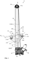
- object moving device 1 illustrated in FIG. 1 is fixed between an inner panel and an outer panel of a door of a vehicle and is applied to a window regulator or the like which lifts and lowers a window of the door (for example, window glass).
- a window regulator or the like which lifts and lowers a window of the door (for example, window glass).
- the present embodiment will be described, unless otherwise noted, such that a longitudinal direction of guide rail 30 is referred to as up-down direction, and that a direction which is parallel to the window glass that is holding object W supported by object moving device 1, and which is perpendicular to the up-down direction is referred to as left-right direction.
- a moving direction of carrier plate 20 is the up-down direction since the window regulator lifts and lowers the window glass.
- object moving device 1 includes, as a mechanism which moves carrier plate 20, direction-changing section 50, cable 60, drive section 40, and drum member 45.
- a driving force of drive section 40 is transmitted to carrier plate 20 via cable 60.
- Carrier plate 20 is configured to be movable on guide rail 30 by driving of drive section 40.
- Drive section 40 is connected to drum member 45.
- Drive section 40 rotates drum member 45 by driving such as driving by a power supply.
- Drum member 45 which rotates by drive section 40 winds and unwinds cable 60.
- Drive section 40 includes, for example, a motor which drives by turning on and off a power supply, and rotates drum member 45 which is connected to drive section 40.
- Drive section 40 is housed in a motor housing and is fixed to a target to be attached (hereinafter, referred to as "attachment target"), such as a base or a vehicle body, via the motor housing.
- attachment target a target to be attached
- the motor housing is fixed to drum housing 47.
- drive section 40 is disposed at a lower end portion of guide rail 30.
- Drive section 40 of the present embodiment is a motor which electrically drives by a current supplied from a battery.
- the motor and drum member 45 transmit rotational motion of the motor to drum member 45 via a power transmission section, such as a worm gear, for example.
- the motor which is drive section 40 rotationally drives in a forward direction and a backward direction, and thereby drum 45 rotates in the forward direction and the backward direction.
- Drum member 45 is connected to drive section 40, and cable 60 is wound around drum member 45.
- a terminal member (cable end) of cable 60 is fixed to drum member 45, and drum member 45 winds and unwinds cable 60.
- drum member 45 includes a locking portion (not illustrated) which houses the terminal member (cable end) of cable 60, and is rotatably housed in drum housing 47.
- Drum member 45 is connected to carrier plate 20 via cable 60.
- Drum member 45 is made of, for example, a resin and/or the like.
- one of cable ends of lifting cable 61 and one of cable ends of lowering cable 62, in which lifting cable 61 and lowering cable 62 are cable 60, are connected to drum member 45, respectively.
- Drum member 45 winds and unwinds lifting cable 61 and lowering cable 62 by the rotation of drum member 45 in the forward direction and the backward direction.
- Lifting cable 61 and lowering cable 62 are wound and unwound by the rotation of drum member 45, and thus, carrier plate 20 is moved.
- drum member 45 of the present embodiment lifting cable 61 and lowering cable 62 are wound in directions opposite to each other.
- Drum member 45 of the present embodiment is connected to both lifting cable 61 and lowering cable 62 at the lower end portion of guide rail 30.
- Drum member 45 rotates in one direction to wind lifting cable 61 and unwind lowering cable 62, and thereby carrier plate 20 is moved upwardly.
- drum member 45 rotates in the other direction to unwind lifting cable 61 and wind lowering cable 62, and thereby carrier plate 20 is moved downwardly.
- Drum housing 47 is made of a resin, for example, and rotatably houses drum member 45.
- drive section 40 is fixed to drum housing 47, and the lower end portion of guide rail 30 is connected to drum housing 47.
- drum housing 47 may be provided at an intermediate position in the up-down direction of guide rail 30 or may be provided apart from guide rail 30 as long as drum housing 47 houses drum member 45.
- Drum member 45 which rotates by drive section 40 is provided at a height position of an intermediate portion in the longitudinal direction of guide rail 30, and a direction-changing member such as a cable guide is provided at the lower end portion of guide rail 30.
- lowering cable 62 is wound around the direction-changing member and is placed between drum member 45 and carrier plate 20, and carrier plate 20 is lifted and lowered via cable 60 which is wound to and unwound from drum member 45.
- Direction-changing section 50 changes a moving direction of cable 60 (specifically, lifting cable 61) on guide rail 30.
- Lifting cable 61 is wound around direction-changing section 50, and direction-changing section 50 changes the moving direction of lifting cable 61.
- Direction-changing section 50 is provided with fixing portion 51 which is fixed to guide rail 30.
- Direction-changing section 50 is made of, for example, a resin, and is connected to an upper end of guide rail 30.
- Fixing portion 51 is provided with fastening portion 51a which is fastened to the attachment target such as a vehicle door by a fastening member (not illustrated) such as a bolt.
- Fastening portion 51a is provided with e.g. an insertion hole through which the fastening member is inserted.
- Fastening portion 51 is fastened to e.g. an inner panel or an outer panel of the vehicle door, and thereby direction-changing section 50 is fixed to the vehicle door.
- direction-changing section 50 for example, a resin-made guide which guides lifting cable 61 along a changing direction, a rotatable pulley or the like is used.
- direction-changing section 50 is a resin-made guide groove which is provided in a circular arc shape.
- Lifting cable 61 slides on direction-changing section 50, and thus, the moving direction of lifting cable 61 is changed.
- the moving direction of lifting cable 61 is changed by direction-changing section 50 from a pulling-downward direction on one end side (a side of drum member 45) to a pulling-upward direction on the other end side (a side of carrier plate 20).
- Cable 60 is a member which moves carrier plate 20 in the up-down direction indicated by an arrow in FIG. 1 .
- cable 60 is connected to carrier plate 20, and the other end of cable 60 is connected to drum member 45. Cable 60 is wound and unwound by the rotation of drum member 45. Cable 60 transmits the driving force of drive section 40 to carrier plate 20. Cable 60 is locked to drum member 45 and carrier plate 20 at the terminal members of both ends of cable 60, respectively. In the locking structure thereof, the terminal members of cable 60 are locked to a terminal member engagement portion which is provided in drum member 45, and to a terminal member engagement portion which is provided in carrier plate 20, respectively, and thus, cable 60 can be locked to drum member 45 and carrier plate 20 so as to enable a predetermined tension to be applied to cable 60.
- cable 60 includes lifting cable 61 and lowering cable 62.
- One end of lifting cable 61 is connected to drum member 45, an intermediate portion located between both ends of cable 60 is wound on direction-changing section 50, and the other end (terminal member 612) of lifting cable 61 is connected to carrier plate 20.
- Lifting cable 61 pulls up carrier plate 20 by the rotation of drum member 45 in a direction of winding lifting cable 61.
- lowering cable 62 is connected to drum member 45, and the other end (terminal member 622) of lowering cable 62 is connected to carrier plate 20.
- Lowering cable 62 is pulled by the rotation of drum member 45 in a direction of winding lowering cable 62, and thus, carrier plate 20 is pulled down.
- Guide rail 30 guides movement of carrier plate 20 in a lifting and lowering direction of holding object W.
- Guide rail 30 is a rail which has substantially the same shaped cross section which extends in the longitudinal direction, and supports carrier plate 20 such that carrier plate 20 is movable along a lifting and lowering path.
- guide rail 30 is provided on a door of a vehicle correspondingly to a lifting and lowering track of holding object W.
- guide rail 30 may be attached to the door of the vehicle with guide rail 30 being inclined to a rear side of the vehicle with respect to a vertical direction of the vehicle, or with guide rail 30 being curved in a width direction of the vehicle.
- Guide rail 30 includes base portion 32 which extends between one end and the other end, and first erected portion (erected portion) 34 and second erected portion 36 which are erected from base portion 32 along an extending direction of base portion 32.
- Base portion 32 has a curved flat-plate shape, corresponds to a bottom surface portion of guide rail 30 which is recessed, and supports first erected portion 34 and second erected portion 36.
- the predetermined direction in which base portion 32 extends is the moving direction of carrier plate 20, and is the lifting and lowering direction of holding object W in the present embodiment.
- First erected portion 34 is provided in one side edge portion along the extending direction of base portion 32.
- First erected portion 34 is provided in a direction which is substantially perpendicular to base portion 32.
- Second erected portion 36 is provided on the other side edge which extends along the extending direction of base portion 32 so as to face first erected portion 34.
- Guide rail 30 is formed in a recessed groove shape with a recessed cross section extending in the longitudinal direction with first erected portion 34, second erected portion 36, and base portion 32 as a bottom portion.
- Carrier plate 20 is slidably fitted to guide rail 30 on a side of an opening of guide rail 30 which is recessed.
- first erected portion 34 and second erected portion 36 are erected in edge portions on both sides of base portion 32, respectively, and also function as guide portions which extend in the extending direction of base portion 32.
- First erected portion 34 includes first surface 342 and second surface 344 which extend in the extending direction of base portion 32.
- First erected portion 34 includes first surface 342 on a side facing outward in a width direction of guide rail 30, and second surface 344 on the rear side thereof. Second surface 344 is located in the inside of the width direction of guide rail 30, where the inside faces second erected portion 36.
- First surface 342 and second surface 344 of the present embodiment constitutes front and rear surfaces of first erected portion 34 which has a plate shape, and are configured to be capable of guiding carrier plate 20.
- First erected portion 34 restrains carrier plate 20 from rotating in directions including a width direction of base portion 32 (a direction perpendicular to both of a length direction and a thickness direction of base portion 32).
- first erected portion 34 is fitted to carrier plate 20, and thereby first erected portion 34 together with second erected portion 36 restrain carrier plate 20 from rotating in the width direction of base portion 32.
- first erected portion 34 At a leading end portion in an erection direction of first erected portion 34, first erected portion 34 includes leading end side portion 35 which protrudes in a direction crossing the erection direction, and which extends along first erected portion 34.
- leading end side portion 35 is formed to have a rib shape.
- leading end side portion 35 is formed so as to be parallel to an arrangement surface of base portion 32.
- Leading end side portion 35 is provided to extend in an extending direction of guide rail 30.
- Holding object W is connected to carrier plate 20, and is lifted and lowered by the movement of carrier plate 20 to open and close a predetermined opening portion (for example, a window). Holding object W switches between a covered state and an opened state of the opening portion.
- a predetermined opening portion for example, a window
- holding object W is a window glass.
- the window glass may slide with a door sash which defines the opening portion (not illustrated), and movement of the window glass may be prevented by the door sash.
- Holding object W sets the opening portion in the covered state by guidance of carrier plate 20 to a position on a side of the upper end of guide rail 30, and sets the opening portion in the opened state in accordance with guidance of carrier plate 20 from the position on the side of the upper end of guide rail 30 to a position on a side of a lower end of guide rail 30.
- Holding object W in the present embodiment is moved by the movement of carrier plate 20 which moves by winding and unwinding cable 60.
- the window glass is adopted as holding object W
- holding object W may be a plate which is formed by a metal, a resin and/or the like other than glass.
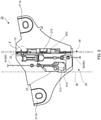
- Carrier plate 20 which is illustrated in FIG. 1 and FIG. 2 holds holding object W, and the movement of carrier plate 20 is guided by guide rail 30.
- Carrier plate 20 is attached to guide rail 30 so as to move on guide rail 30 along the extending direction of base portion 32.
- Carrier plate 20 holds holding object W which is connected to carrier plate 20 via glass holder 13.
- Carrier plate 20 is moved by guide rail 30 to one side, that is, an upper side of the moving direction of carrier plate 20.
- Carrier plate 20 moves to a position which is defined as an upper limit end of the movement to the one side of carrier plate 20, that is, a position which causes a state where the window is completely covered and tightly closed (or a closed state of the opening portion) with holding object W. Further, carrier plate 20 moves to the other side, that is, a lower side of the moving direction of carrier plate 20.
- Carrier plate 20 moves to a position which is defined as a lower limit position of the movement to the other side of carrier plate 20, for example, a position where the window is set to a fully opened state by the movement of the window glass which is holding object W.
- these positions to be set on the one side and the other side of the moving direction of carrier plate 20 are the positions on the side of the upper end and on the side of the lower end of guide rail 30 which extends in the up-down direction.
- Carrier plate 20 moves on guide rail 30 by the driving of drive section 40, and stops moving by stopping of drive section 40.
- Cable 60 which is unwound from drum member 45 by the driving of drive section 40 is connected to carrier plate 20 such that carrier plate 20 can move on guide rail 30 by movement of cable 60.
- carrier plate 20 is fitted to guide rail 30, and thereby carrier plate 20 is provided to be slidable on guide rail 30 in the up-down direction in a state where the movement of carrier plate 20 in the left-right direction is regulated by the erected portion of guide rail 30.
- Carrier plate 20 includes main body portion 21 which holds holding object W, and slit 22 which houses first erected portion 34.
- Main body portion 21 is, for example, a plate-like body which has a predetermined thickness.
- Main body portion 21 is provided with attachment portions 211a and 211b to which the glass holders are attached, and end housing portions 213 and 215. Attachment portions 211a and 211b, and end housing portions 213 and 215 may be directly or indirectly provided in main body portion 21.
- Main body portion 21 includes slit 22 which houses first erected portion 34.
- Slit 22 houses first erected portion 34 of guide rail 30, and thus, carrier plate 20 is freely movably guided by first erected portion 34 in an extending direction of first erected portion 34.
- slit 22 is provided extending along the moving direction of carrier plate 20 on a surface on a guide-rail-side of carrier plate 20 as illustrated in FIG. 1 or FIG 2 .
- Slit 22 may be configured in any way as long as carrier plate 20 is guided in the extending direction of guide rail 30 with first erected portion 34 which is inserted into slit 22 and which is housed by slit 22.
- Main body portion 21 has a thickness from a surface on a side thereof opposite to a side thereof, to which the guide rail is attached, to the guide-rail-side thereof, in which the thickness is larger than an erection height of first erected portion 34.
- Slit 22 is provided over the up-down direction in a protrusion portion of slit 22, and has a depth in a thickness direction of the protrusion portion.
- Slit 22 has a substantially L-shape in a cross section of carrier plate 20.
- Attachment portions 211a and 211b are portions to each of which glass holder 13 is attached, and are provided in an upper end portion of main body portion 21. Glass holder 13 which is connected to holding object W is attached to each of attachment portions 211a and 211b.
- each of attachment portions 211a and 211b includes an attachment hole which opens in a thickness direction of main body portion 21. Glass holder 13 is attached to each of attachment portions 211a and 211b via the fastening member, such as a screw and a bolt, which is inserted into each of the attachment holes (see FIG. 1 ).
- attachment portions 211a and 211b are disposed so as to be apart from each other at a predetermined distance in the width direction of guide rail 30.
- attachment portions 211a and 211b are provided in both side end portions of the upper end portion, respectively, in which the both side end portions are apart from each other in the width direction.
- Each of end housing portions 213 and 215 houses an end portion which is the terminal member of cable 60, and connects cable 60 (61, 62) to carrier plate 20.
- the end housing portion (213, 215) includes end housing portion 213 which houses terminal member 612 of lifting cable 61 for lifting carrier plate 20, and end housing portion 215 which houses terminal member 622 of lowering cable 62 for lowering carrier plate 20.
- Lifting cable 61 and lowering cable 62 are led out from respective end housing portions 213 and 215 of carrier plate 20 such that a lead-out portion of each of lifting cable 61 and lowering cable 62 serves as a supporting point for lifting or lowering carrier plate 20.
- Slit 22 houses first erected portion 34 of guide rail 30.
- Slit 22 is formed by one side portion which includes first edge portion 26 and the other side portion which includes second edge portion 27.
- the one side portion which includes first edge portion 26 includes a leading end side portion-housing portion which houses leading end side portion 35 and which is connected to a bottom side of slit 22.
- Slit 22 is formed by first edge portion 26 which is disposed on a side of the first surface, and second edge portion 27 which is disposed on a side of the second surface.
- first edge portion 26 and second edge portion 27 include abutting surfaces which abut on first surface 342 and second surface 344, respectively.
- carrier plate 20 is guided by first erected portion 34 and is freely movable in the extending direction of first erected portion 34.
- slit 22 is provided extending along the moving direction of carrier plate 20 on a rear surface of carrier plate 20 as illustrated in the figures.
- carrier plate 20 slit 22 is freely slidably fitted to first erected portion 34 of guide rail 30 on a side of the rear surface of main body portion 21, and engagement projection portion 23 engages with second erected portion 36 of guide rail 30.
- carrier plate 20 is provided to be slidable on guide rail 30 in the up-down direction in a state where the movement of carrier plate 20 in the left-right direction is regulated by guide rail 30.
- Slit 22 is formed by first edge portion 26 which is disposed on the side of first surface 342 of first erected portion 34, and second edge portion 27 which is disposed on the side of second surface 344 of first erected portion 34.
- slit 22 opens on the surface on the guide-rail-side of carrier plate 20, has a depth in a thickness direction of carrier plate 20, and is formed by first edge portion 26 and second edge portion 27 which are disposed to face each other.
- First edge portion 26 includes first sliding surface 262 which faces first surface 342 of first erected portion 34.
- Second edge portion 27 includes second sliding surface 272 which faces second surface 344 of first erected portion 34.
- First sliding surface 262 is a surface which is slidable with first surface 342 of first erected portion 34.
- Second sliding surface 272 is a surface which is slidable with second surface 344 of first erected portion 34.
- First sliding surface 262 and second sliding surface 272 have a distance from first surface 342 and second surface 344 of first erected portion 34, in which the distance which causes first sliding surface 262 and second sliding surface 272 to abut on first surface 342 and second surface 344, or the distance which restrains carrier plate 20 from rotating in a direction which is perpendicular to an axis of guide rail 30.
- carrier plate 20 can smoothly move along the axial direction, that is, the longitudinal direction of guide rail 30 without rotating in the direction perpendicular to the axis of guide rail 30.
- Carrier plate 20 may include, on first sliding surface 262, protrusion portion 266 which protrudes to the side of first surface 342.
- carrier plate 20 moves on guide rail 30, protrusion portion 266 of first sliding surface 262 slides with first surface 342.
- carrier plate 20 can slide with guide rail 30 while coming into point contact with each other, and the sliding can be smoothly performed with reduced friction.
- cutout portion 70 is provided in at least one of first edge portion 26 and second edge portion 27.
- cutout portion 70 is provided in first edge portion 26 so as to be recessed in a direction away from second edge portion 27.
- Cutout portion 70 includes opening 72 which faces first erected portion 34.
- Cutout portion 70 forms space portion 74, and can store grease G in a semisolid state between carrier plate 20 and first erected portion 34. Cutout portion 70 may be formed in any way as long as cutout portion 70 includes a wall surface capable of forming space portion 74 and can store grease G
- cutout portion 70 is provided on one side of the erection direction of first erected portion 34 when carrier plate 20 is attached to guide rail 30.
- cutout portion 70 opens on the guide-rail-side of carrier plate 20.
- Cutout portion 70 is provided in first erected portion 34 in the present embodiment, but may be provided in second erected portion 36 or may be provided in both first erected portion 34 and second erected portion 36.
- Cutout portion 70 is in communication with hole portion 217 which is provided in main body portion 21.
- Hole portion 217 and cutout portion 70 are provided at a position which enables grease G to reach cutout portion 70 when grease G is injected into hole portion 217 in a state where carrier plate 20 is attached to guide rail 30.
- Opening 72 causes first erected portion 34 to face the interior of cutout portion 70, and space portion 74 in the interior is disposed adjacent to first erected portion 34.
- Space portion 74 is interposed between erected portion 34 and carrier plate 20, and thereby to store grease G which reduces friction and which makes the sliding smooth.
- Space portion 74 is a space which has a depth along the erection direction of the erected portion.
- Space portion 74 has a size capable of storing an amount of grease G which adheres to first erected portion 34 and which is spread and applied from space portion 74 even when first erected portion 34 is reciprocated a predetermined number of times.
- first erected portion 34 erected on base portion 32 in guide rail 30 is housed in slit 22 of carrier plate 20 which holds the holding object.
- Carrier plate 20 is attached to guide rail 30 so as to move on guide rail 30 along the extending direction of base portion 32.
- Slit 22 is formed by first edge portion 26 which is disposed on the side of first surface 342 extending in the extending direction of first erected portion 34, and second edge portion 27 which is disposed on the side of second surface 344 extending in the extending direction of first erected portion 34.
- Cutout portion 70 which includes opening 72 facing first erected portion 34 is provided in at least one of first edge portion 26 and second edge portion 27. Cutout portion 70 includes space portion 74 in which storing grease G can be stored.
- first erected portion 34 moves in slit 22 when carrier plate 20 moves on guide rail 30.
- space portion 74 of cutout portion 70 moves relative to first erected portion 34 along first erected portion 34.
- Grease G stored in cutout portion 70 adheres to a portion of first erected portion 34 which faces space portion 74.
- Grease G is applied to at least first surface 342 of first erected portion 34.
- Grease G is also applied to first edge portion 26 of slit 22 (first sliding surface 262) with which first surface 342 slides.
- grease G which adheres to first erected portion 34 moves following the sliding in slit 22 of first erected portion 34, and grease G in space portion 74 also moves following the sliding. With this movement, grease G is spread over the sliding portion of both.
- grease G is injected through hole portion 217, grease G is filled into the leading end side portion-housing portion which houses leading end side portion 35, and is filled into slit 22 as well. Accordingly, grease G is applied not only to first surface 342 of first erected portion 34, but also to one surface or the other surface of leading end side portion 35 which is continuous to first surface 342, to second surface 344 which is continuous to the aforementioned other surface, or the like, and thus, grease G is applied to first erected portion 34 in its entirety located in slit 22.
- grease G can be efficiently applied to the sliding portion between carrier plate 20 and guide rail 30, and relative movement by carrier plate 20 and guide rail 30, specifically, movement of carrier plate 20 with respect to guide rail 30 can be smoothly performed. Further, grease G can be easily injected into space portion 74 of cutout portion 70 through hole portion 217 from a side of carrier plate 20 which is opposite to guide rail 30, that is, from a front side of carrier plate 20, and grease application work can also be easily performed. Accordingly, wear due to first erected portion 34 of the guide rail is restrained in the object moving device which uses carrier plate 20.
- the object moving device exhibits an effect capable of efficiently and smoothly moving a holding object which a carrier plate holds when moving the holding object, and is useful as an object moving device to be used in a window regulator.
Landscapes
- Engineering & Computer Science (AREA)
- Mechanical Engineering (AREA)
- General Engineering & Computer Science (AREA)
- Window Of Vehicle (AREA)
- Power-Operated Mechanisms For Wings (AREA)
Claims (4)
- Objektbewegungsvorrichtung (1) mit:einer Führungsschiene (30), die einen sich in einer vorbestimmten Richtung erstreckenden Basisabschnitt (32) und einen auf dem Basisabschnitt (32) in Erstreckungsrichtung des Basisabschnitts (32) aufgerichteten Abschnitt (34) aufweist; undeiner Trägerplatte (20), die einen ein Halteobjekt haltenden Hauptkörperabschnitt (21) und einen den aufgerichteten Abschnitt (34) aufnehmenden Schlitz (22) aufweist, wobeidie Trägerplatte (20) an der Führungsschiene (30) so angebracht ist, dass sie sich auf der Führungsschiene (30) in der Erstreckungsrichtung bewegt,der aufgerichtete Abschnitt (34) eine erste Fläche (342) und eine zweite Fläche (344) aufweist, die sich in der Erstreckungsrichtung erstrecken,der Schlitz (22) durch einen auf der Seite der ersten Fläche (342) des aufgerichteten Abschnitts (34) angeordneten ersten Randabschnitt (26) und einen auf der Seite der zweiten Fläche (344) des aufgerichteten Abschnitts (34) angeordneten zweiten Randabschnitt (27) gebildet ist,in wenigstens dem ersten Randabschnitt (26) oder zweiten Randabschnitt (27) eine Aussparung (70) mit einer dem aufgerichteten Abschnitt (34) gegenüberliegenden Öffnung vorgesehen ist,die Aussparung (70) einen Raum (74) zur Einlagerung von Schmiermittel aufweist, unddas in der Aussparung (70) eingelagerte Schmiermittel auf den aufgerichteten Abschnitt (34) aufgebracht wird, der in dem Schlitz (22) gleitet, wenn sich die Trägerplatte (20) auf der Führungsschiene (30) bewegt.
- Objektbewegungsvorrichtung (1), wobeidie Aussparung (70) auf der einen Seite der Aufrichtrichtung des aufgerichteten Abschnitts (34) vorgesehen ist, wenn die Trägerplatte (20) an der Führungsschiene (30) angebracht ist,der Hauptkörperabschnitt (21) mit einem Loch (217) auf der anderen Seite der Aufrichtrichtung versehen ist, unddas Loch (217) und die Aussparung (70) an einer Position vorgesehen sind, die in einem Zustand, in dem die Trägerplatte (20) an der Führungsschiene (30) befestigt ist, zulässt, dass das Schmiermittel die Aussparung (70) erreicht, wenn das Schmiermittel in das Loch (217) eingespritzt wird.
- Objektbewegungsvorrichtung (1) nach Anspruch 1, wobei die Trägerplatte (20) Folgendes aufweist:eine der ersten Fläche (342) am ersten Kantenabschnitt (26) gegenüberliegende erste Gleitfläche (262); undeine der zweiten Fläche (344) am zweiten Randabschnitt (27) gegenüberliegende zweite Gleitfläche (272), wobeidie erste Gleitfläche (262) und die zweite Gleitfläche (272) einen Abstand zur ersten Fläche (342) und zweiten Fläche (344) des aufgerichteten Abschnitts (34) haben, wobei der Abstand bewirkt, dass die erste Gleitfläche (262) und die zweite Gleitfläche (272) gegen die erste Fläche (342) und zweite Fläche (344) stoßen, oder der Abstand verhindert, dass die Trägerplatte (20) sich in eine Richtung senkrecht zu einer Achse der Führungsschiene (30) dreht.
- Objektbewegungsvorrichtung (1) nach Anspruch 3, wobeidie erste Gleitfläche (262) eine Vielzahl von zur Seite der ersten Fläche (342) hin vorstehenden Vorsprüngen (266) aufweist, undwenn sich die Trägerplatte (20) auf der Führungsschiene (30) bewegt, die Vorsprünge (266) der ersten Gleitfläche (262) an der ersten Fläche (342) gleiten.
Applications Claiming Priority (1)
| Application Number | Priority Date | Filing Date | Title |
|---|---|---|---|
| JP2019120116A JP6954956B2 (ja) | 2019-06-27 | 2019-06-27 | 対象物移動装置 |
Publications (2)
| Publication Number | Publication Date |
|---|---|
| EP3757339A1 EP3757339A1 (de) | 2020-12-30 |
| EP3757339B1 true EP3757339B1 (de) | 2022-02-09 |
Family
ID=71138671
Family Applications (1)
| Application Number | Title | Priority Date | Filing Date |
|---|---|---|---|
| EP20181872.1A Active EP3757339B1 (de) | 2019-06-27 | 2020-06-24 | Objektbewegungsvorrichtung |
Country Status (4)
| Country | Link |
|---|---|
| US (1) | US11286704B2 (de) |
| EP (1) | EP3757339B1 (de) |
| JP (1) | JP6954956B2 (de) |
| CN (1) | CN112145018B (de) |
Families Citing this family (6)
| Publication number | Priority date | Publication date | Assignee | Title |
|---|---|---|---|---|
| JP7351237B2 (ja) * | 2020-02-26 | 2023-09-27 | 株式会社アイシン | ウインドレギュレータ |
| JP7146357B2 (ja) * | 2020-07-20 | 2022-10-04 | 株式会社城南製作所 | ウインドレギュレータ |
| DE102021205768A1 (de) * | 2021-06-08 | 2022-12-08 | Brose Fahrzeugteile Se & Co. Kommanditgesellschaft, Bamberg | Fensterheber für ein Kraftfahrzeug |
| CN113629471B (zh) * | 2021-10-09 | 2021-12-10 | 商客通尚景科技江苏有限公司 | 一种多芯排线熔焊设备 |
| JP7789635B2 (ja) * | 2022-07-28 | 2025-12-22 | 株式会社ハイレックスコーポレーション | キャリアプレートおよびウインドレギュレータ |
| JP2024064809A (ja) * | 2022-10-28 | 2024-05-14 | 株式会社ハイレックスコーポレーション | 対象物移動装置およびウインドレギュレータ |
Family Cites Families (22)
| Publication number | Priority date | Publication date | Assignee | Title |
|---|---|---|---|---|
| NL6806440A (de) * | 1967-07-05 | 1969-01-07 | ||
| JPS58181885U (ja) * | 1982-05-31 | 1983-12-05 | ダイキヨ−・ペパスト株式会社 | 車両用ウインドガラス開閉装置のガイド装置 |
| JP3269259B2 (ja) * | 1994-05-24 | 2002-03-25 | 日産自動車株式会社 | ワイヤドラム式レギュレータのキャリアプレート構造 |
| FR2813914A1 (fr) * | 2000-09-14 | 2002-03-15 | Meritor Light Vehicle Sys Ltd | Curseur de leve-vitre avec reservoir de graisse |
| DE10207140B4 (de) * | 2002-02-20 | 2005-10-06 | Brose Fahrzeugteile Gmbh & Co. Kg, Coburg | Seilfensterheber für eine Fensterscheibe |
| JP4446450B2 (ja) * | 2004-03-29 | 2010-04-07 | 日産自動車株式会社 | 自動車用摺動装置 |
| JP4727547B2 (ja) * | 2006-10-11 | 2011-07-20 | 三井金属アクト株式会社 | 車両用ウインドウレギュレータ装置 |
| US20110067311A1 (en) * | 2009-09-18 | 2011-03-24 | Thomas Peter Corden | Window Regulator Lifter Plate With Integrated Lubrication System |
| US20130111816A1 (en) * | 2011-11-07 | 2013-05-09 | Shiroki Corporation | Window regulator for vehicle |
| CN203097562U (zh) * | 2013-02-22 | 2013-07-31 | 上海通用汽车有限公司 | 汽车玻璃升降器滑块及玻璃升降器 |
| CN203755879U (zh) * | 2013-12-19 | 2014-08-06 | 安徽工程大学 | 一种玻璃升降器托架润滑脂保存机构 |
| US9682389B2 (en) * | 2014-12-29 | 2017-06-20 | Yong Lee | Automotive, electric window servicing apparatus and kit, and method for using same |
| JP2017002673A (ja) * | 2015-06-15 | 2017-01-05 | 株式会社ハイレックスコーポレーション | 対象物移動装置 |
| JP6846116B2 (ja) * | 2016-04-12 | 2021-03-24 | シロキ工業株式会社 | 車両用開閉体駆動装置 |
| JP6723801B2 (ja) * | 2016-04-12 | 2020-07-15 | シロキ工業株式会社 | 車両用開閉体駆動装置の組付判定方法 |
| JP6682345B2 (ja) * | 2016-05-12 | 2020-04-15 | シロキ工業株式会社 | ウインドレギュレータ |
| CN206487300U (zh) * | 2017-01-06 | 2017-09-12 | 北京汽车股份有限公司 | 玻璃升降器及汽车 |
| JP6762970B2 (ja) * | 2018-01-19 | 2020-09-30 | 株式会社城南製作所 | ウインドレギュレータ |
| DE102018213172A1 (de) * | 2018-08-07 | 2020-02-13 | Brose Fahrzeugteile Gmbh & Co. Kommanditgesellschaft, Bamberg | Schienengleiter für einen Fensterheber eines Kraftfahrzeugs |
| US20200071981A1 (en) * | 2018-08-31 | 2020-03-05 | Brose Fahrzeugteile Gmbh & Co. Kommanditgesellschaft, Bamberg | Window lifter assembly for adjusting a window pane |
| JP7187980B2 (ja) * | 2018-10-29 | 2022-12-13 | 株式会社アイシン | ウインドレギュレータ及びその組付方法 |
| JP7187981B2 (ja) * | 2018-10-29 | 2022-12-13 | 株式会社アイシン | ウインドレギュレータ及びその組付方法 |
-
2019
- 2019-06-27 JP JP2019120116A patent/JP6954956B2/ja active Active
-
2020
- 2020-06-24 EP EP20181872.1A patent/EP3757339B1/de active Active
- 2020-06-26 US US16/913,497 patent/US11286704B2/en active Active
- 2020-06-28 CN CN202010600054.7A patent/CN112145018B/zh active Active
Also Published As
| Publication number | Publication date |
|---|---|
| CN112145018B (zh) | 2022-07-19 |
| JP6954956B2 (ja) | 2021-10-27 |
| JP2021004533A (ja) | 2021-01-14 |
| US11286704B2 (en) | 2022-03-29 |
| CN112145018A (zh) | 2020-12-29 |
| EP3757339A1 (de) | 2020-12-30 |
| US20200408026A1 (en) | 2020-12-31 |
Similar Documents
| Publication | Publication Date | Title |
|---|---|---|
| EP3757339B1 (de) | Objektbewegungsvorrichtung | |
| CN101925481B (zh) | 用于用导引元件和滑动件形成的滑闸关闭形成于车辆车身中的开口的装置以及对应的车辆 | |
| US20080216972A1 (en) | Automatically actuable side window roller blind | |
| US20090019776A1 (en) | Cable guide and sliding door drive mechanism using the same | |
| JP6844815B2 (ja) | 車両用ワイヤ式ウインドレギュレータ装置 | |
| JP5316791B2 (ja) | ロールスクリーン装置 | |
| JP2013052709A (ja) | 車両用ウインドウシェード装置 | |
| EP2546447B1 (de) | Kraftfahrzeug mit einer Schiebetür und einem Betätigungsmechanismus für die Schiebetür | |
| EP3561211B1 (de) | Fensterglashebevorrichtung | |
| US12083870B2 (en) | Carrier plate and object movement device | |
| US10975604B2 (en) | Window regulator | |
| JP2969427B2 (ja) | 車両用スライドドアの開閉装置 | |
| JPH11122791A (ja) | 開閉部材構造 | |
| CN219953061U (zh) | 窗口调节器 | |
| JP2010236264A (ja) | パワースライド装置 | |
| JP5930665B2 (ja) | 車両用ウインドレギュレータ装置 | |
| US20230279713A1 (en) | Window regulator for a frameless system | |
| JP5478932B2 (ja) | パワースライド装置 | |
| CN218780190U (zh) | 用于升高和降低车辆窗口的窗口调节器 | |
| JP4226535B2 (ja) | ドアパネル構造およびウインドレギュレータ | |
| JP6796003B2 (ja) | 対象物移動装置 | |
| WO2012137716A1 (ja) | シェード装置 | |
| JP2008208641A (ja) | 車両用自動開閉装置 | |
| CN223880953U (zh) | 一种隐藏式尾门开启限位装置 | |
| JP7586390B2 (ja) | 車両用スライドドア開閉装置 |
Legal Events
| Date | Code | Title | Description |
|---|---|---|---|
| PUAI | Public reference made under article 153(3) epc to a published international application that has entered the european phase |
Free format text: ORIGINAL CODE: 0009012 |
|
| STAA | Information on the status of an ep patent application or granted ep patent |
Free format text: STATUS: REQUEST FOR EXAMINATION WAS MADE |
|
| 17P | Request for examination filed |
Effective date: 20200624 |
|
| AK | Designated contracting states |
Kind code of ref document: A1 Designated state(s): AL AT BE BG CH CY CZ DE DK EE ES FI FR GB GR HR HU IE IS IT LI LT LU LV MC MK MT NL NO PL PT RO RS SE SI SK SM TR |
|
| AX | Request for extension of the european patent |
Extension state: BA ME |
|
| GRAP | Despatch of communication of intention to grant a patent |
Free format text: ORIGINAL CODE: EPIDOSNIGR1 |
|
| STAA | Information on the status of an ep patent application or granted ep patent |
Free format text: STATUS: GRANT OF PATENT IS INTENDED |
|
| INTG | Intention to grant announced |
Effective date: 20210820 |
|
| RIN1 | Information on inventor provided before grant (corrected) |
Inventor name: NAGASAKI, TETSUYA Inventor name: TAKAOKA, HIROYUKI |
|
| GRAS | Grant fee paid |
Free format text: ORIGINAL CODE: EPIDOSNIGR3 |
|
| GRAA | (expected) grant |
Free format text: ORIGINAL CODE: 0009210 |
|
| STAA | Information on the status of an ep patent application or granted ep patent |
Free format text: STATUS: THE PATENT HAS BEEN GRANTED |
|
| AK | Designated contracting states |
Kind code of ref document: B1 Designated state(s): AL AT BE BG CH CY CZ DE DK EE ES FI FR GB GR HR HU IE IS IT LI LT LU LV MC MK MT NL NO PL PT RO RS SE SI SK SM TR |
|
| RAP3 | Party data changed (applicant data changed or rights of an application transferred) |
Owner name: TOYOTA JIDOSHA KABUSHIKI KAISHA Owner name: HI-LEX CORPORATION |
|
| REG | Reference to a national code |
Ref country code: GB Ref legal event code: FG4D |
|
| RIN1 | Information on inventor provided before grant (corrected) |
Inventor name: NAGASAKI, TETSUYA Inventor name: TAKAOKA, HIROYUKI |
|
| REG | Reference to a national code |
Ref country code: CH Ref legal event code: EP Ref country code: AT Ref legal event code: REF Ref document number: 1467613 Country of ref document: AT Kind code of ref document: T Effective date: 20220215 |
|
| REG | Reference to a national code |
Ref country code: DE Ref legal event code: R096 Ref document number: 602020001796 Country of ref document: DE |
|
| REG | Reference to a national code |
Ref country code: IE Ref legal event code: FG4D |
|
| REG | Reference to a national code |
Ref country code: LT Ref legal event code: MG9D |
|
| REG | Reference to a national code |
Ref country code: NL Ref legal event code: MP Effective date: 20220209 |
|
| REG | Reference to a national code |
Ref country code: AT Ref legal event code: MK05 Ref document number: 1467613 Country of ref document: AT Kind code of ref document: T Effective date: 20220209 |
|
| PG25 | Lapsed in a contracting state [announced via postgrant information from national office to epo] |
Ref country code: SE Free format text: LAPSE BECAUSE OF FAILURE TO SUBMIT A TRANSLATION OF THE DESCRIPTION OR TO PAY THE FEE WITHIN THE PRESCRIBED TIME-LIMIT Effective date: 20220209 Ref country code: RS Free format text: LAPSE BECAUSE OF FAILURE TO SUBMIT A TRANSLATION OF THE DESCRIPTION OR TO PAY THE FEE WITHIN THE PRESCRIBED TIME-LIMIT Effective date: 20220209 Ref country code: PT Free format text: LAPSE BECAUSE OF FAILURE TO SUBMIT A TRANSLATION OF THE DESCRIPTION OR TO PAY THE FEE WITHIN THE PRESCRIBED TIME-LIMIT Effective date: 20220609 Ref country code: NO Free format text: LAPSE BECAUSE OF FAILURE TO SUBMIT A TRANSLATION OF THE DESCRIPTION OR TO PAY THE FEE WITHIN THE PRESCRIBED TIME-LIMIT Effective date: 20220509 Ref country code: NL Free format text: LAPSE BECAUSE OF FAILURE TO SUBMIT A TRANSLATION OF THE DESCRIPTION OR TO PAY THE FEE WITHIN THE PRESCRIBED TIME-LIMIT Effective date: 20220209 Ref country code: LT Free format text: LAPSE BECAUSE OF FAILURE TO SUBMIT A TRANSLATION OF THE DESCRIPTION OR TO PAY THE FEE WITHIN THE PRESCRIBED TIME-LIMIT Effective date: 20220209 Ref country code: HR Free format text: LAPSE BECAUSE OF FAILURE TO SUBMIT A TRANSLATION OF THE DESCRIPTION OR TO PAY THE FEE WITHIN THE PRESCRIBED TIME-LIMIT Effective date: 20220209 Ref country code: ES Free format text: LAPSE BECAUSE OF FAILURE TO SUBMIT A TRANSLATION OF THE DESCRIPTION OR TO PAY THE FEE WITHIN THE PRESCRIBED TIME-LIMIT Effective date: 20220209 Ref country code: BG Free format text: LAPSE BECAUSE OF FAILURE TO SUBMIT A TRANSLATION OF THE DESCRIPTION OR TO PAY THE FEE WITHIN THE PRESCRIBED TIME-LIMIT Effective date: 20220509 |
|
| PGFP | Annual fee paid to national office [announced via postgrant information from national office to epo] |
Ref country code: DE Payment date: 20220601 Year of fee payment: 3 |
|
| PG25 | Lapsed in a contracting state [announced via postgrant information from national office to epo] |
Ref country code: PL Free format text: LAPSE BECAUSE OF FAILURE TO SUBMIT A TRANSLATION OF THE DESCRIPTION OR TO PAY THE FEE WITHIN THE PRESCRIBED TIME-LIMIT Effective date: 20220209 Ref country code: LV Free format text: LAPSE BECAUSE OF FAILURE TO SUBMIT A TRANSLATION OF THE DESCRIPTION OR TO PAY THE FEE WITHIN THE PRESCRIBED TIME-LIMIT Effective date: 20220209 Ref country code: GR Free format text: LAPSE BECAUSE OF FAILURE TO SUBMIT A TRANSLATION OF THE DESCRIPTION OR TO PAY THE FEE WITHIN THE PRESCRIBED TIME-LIMIT Effective date: 20220510 Ref country code: FI Free format text: LAPSE BECAUSE OF FAILURE TO SUBMIT A TRANSLATION OF THE DESCRIPTION OR TO PAY THE FEE WITHIN THE PRESCRIBED TIME-LIMIT Effective date: 20220209 Ref country code: AT Free format text: LAPSE BECAUSE OF FAILURE TO SUBMIT A TRANSLATION OF THE DESCRIPTION OR TO PAY THE FEE WITHIN THE PRESCRIBED TIME-LIMIT Effective date: 20220209 |
|
| PG25 | Lapsed in a contracting state [announced via postgrant information from national office to epo] |
Ref country code: IS Free format text: LAPSE BECAUSE OF FAILURE TO SUBMIT A TRANSLATION OF THE DESCRIPTION OR TO PAY THE FEE WITHIN THE PRESCRIBED TIME-LIMIT Effective date: 20220609 |
|
| PG25 | Lapsed in a contracting state [announced via postgrant information from national office to epo] |
Ref country code: SM Free format text: LAPSE BECAUSE OF FAILURE TO SUBMIT A TRANSLATION OF THE DESCRIPTION OR TO PAY THE FEE WITHIN THE PRESCRIBED TIME-LIMIT Effective date: 20220209 Ref country code: SK Free format text: LAPSE BECAUSE OF FAILURE TO SUBMIT A TRANSLATION OF THE DESCRIPTION OR TO PAY THE FEE WITHIN THE PRESCRIBED TIME-LIMIT Effective date: 20220209 Ref country code: RO Free format text: LAPSE BECAUSE OF FAILURE TO SUBMIT A TRANSLATION OF THE DESCRIPTION OR TO PAY THE FEE WITHIN THE PRESCRIBED TIME-LIMIT Effective date: 20220209 Ref country code: EE Free format text: LAPSE BECAUSE OF FAILURE TO SUBMIT A TRANSLATION OF THE DESCRIPTION OR TO PAY THE FEE WITHIN THE PRESCRIBED TIME-LIMIT Effective date: 20220209 Ref country code: DK Free format text: LAPSE BECAUSE OF FAILURE TO SUBMIT A TRANSLATION OF THE DESCRIPTION OR TO PAY THE FEE WITHIN THE PRESCRIBED TIME-LIMIT Effective date: 20220209 Ref country code: CZ Free format text: LAPSE BECAUSE OF FAILURE TO SUBMIT A TRANSLATION OF THE DESCRIPTION OR TO PAY THE FEE WITHIN THE PRESCRIBED TIME-LIMIT Effective date: 20220209 |
|
| REG | Reference to a national code |
Ref country code: DE Ref legal event code: R097 Ref document number: 602020001796 Country of ref document: DE |
|
| PG25 | Lapsed in a contracting state [announced via postgrant information from national office to epo] |
Ref country code: AL Free format text: LAPSE BECAUSE OF FAILURE TO SUBMIT A TRANSLATION OF THE DESCRIPTION OR TO PAY THE FEE WITHIN THE PRESCRIBED TIME-LIMIT Effective date: 20220209 |
|
| PLBE | No opposition filed within time limit |
Free format text: ORIGINAL CODE: 0009261 |
|
| STAA | Information on the status of an ep patent application or granted ep patent |
Free format text: STATUS: NO OPPOSITION FILED WITHIN TIME LIMIT |
|
| 26N | No opposition filed |
Effective date: 20221110 |
|
| PG25 | Lapsed in a contracting state [announced via postgrant information from national office to epo] |
Ref country code: MC Free format text: LAPSE BECAUSE OF FAILURE TO SUBMIT A TRANSLATION OF THE DESCRIPTION OR TO PAY THE FEE WITHIN THE PRESCRIBED TIME-LIMIT Effective date: 20220209 |
|
| REG | Reference to a national code |
Ref country code: BE Ref legal event code: MM Effective date: 20220630 |
|
| PG25 | Lapsed in a contracting state [announced via postgrant information from national office to epo] |
Ref country code: SI Free format text: LAPSE BECAUSE OF FAILURE TO SUBMIT A TRANSLATION OF THE DESCRIPTION OR TO PAY THE FEE WITHIN THE PRESCRIBED TIME-LIMIT Effective date: 20220209 |
|
| PG25 | Lapsed in a contracting state [announced via postgrant information from national office to epo] |
Ref country code: LU Free format text: LAPSE BECAUSE OF NON-PAYMENT OF DUE FEES Effective date: 20220624 Ref country code: IE Free format text: LAPSE BECAUSE OF NON-PAYMENT OF DUE FEES Effective date: 20220624 |
|
| PG25 | Lapsed in a contracting state [announced via postgrant information from national office to epo] |
Ref country code: BE Free format text: LAPSE BECAUSE OF NON-PAYMENT OF DUE FEES Effective date: 20220630 |
|
| PG25 | Lapsed in a contracting state [announced via postgrant information from national office to epo] |
Ref country code: IT Free format text: LAPSE BECAUSE OF FAILURE TO SUBMIT A TRANSLATION OF THE DESCRIPTION OR TO PAY THE FEE WITHIN THE PRESCRIBED TIME-LIMIT Effective date: 20220209 |
|
| REG | Reference to a national code |
Ref country code: DE Ref legal event code: R119 Ref document number: 602020001796 Country of ref document: DE |
|
| REG | Reference to a national code |
Ref country code: CH Ref legal event code: PL |
|
| PG25 | Lapsed in a contracting state [announced via postgrant information from national office to epo] |
Ref country code: MK Free format text: LAPSE BECAUSE OF FAILURE TO SUBMIT A TRANSLATION OF THE DESCRIPTION OR TO PAY THE FEE WITHIN THE PRESCRIBED TIME-LIMIT Effective date: 20220209 Ref country code: DE Free format text: LAPSE BECAUSE OF NON-PAYMENT OF DUE FEES Effective date: 20240103 Ref country code: CY Free format text: LAPSE BECAUSE OF FAILURE TO SUBMIT A TRANSLATION OF THE DESCRIPTION OR TO PAY THE FEE WITHIN THE PRESCRIBED TIME-LIMIT Effective date: 20220209 Ref country code: CH Free format text: LAPSE BECAUSE OF NON-PAYMENT OF DUE FEES Effective date: 20230630 |
|
| PG25 | Lapsed in a contracting state [announced via postgrant information from national office to epo] |
Ref country code: HU Free format text: LAPSE BECAUSE OF FAILURE TO SUBMIT A TRANSLATION OF THE DESCRIPTION OR TO PAY THE FEE WITHIN THE PRESCRIBED TIME-LIMIT; INVALID AB INITIO Effective date: 20200624 |
|
| PG25 | Lapsed in a contracting state [announced via postgrant information from national office to epo] |
Ref country code: TR Free format text: LAPSE BECAUSE OF FAILURE TO SUBMIT A TRANSLATION OF THE DESCRIPTION OR TO PAY THE FEE WITHIN THE PRESCRIBED TIME-LIMIT Effective date: 20220209 |
|
| PGFP | Annual fee paid to national office [announced via postgrant information from national office to epo] |
Ref country code: FR Payment date: 20240621 Year of fee payment: 5 |
|
| PG25 | Lapsed in a contracting state [announced via postgrant information from national office to epo] |
Ref country code: MT Free format text: LAPSE BECAUSE OF FAILURE TO SUBMIT A TRANSLATION OF THE DESCRIPTION OR TO PAY THE FEE WITHIN THE PRESCRIBED TIME-LIMIT Effective date: 20220209 |
|
| GBPC | Gb: european patent ceased through non-payment of renewal fee |
Effective date: 20240624 |
|
| PG25 | Lapsed in a contracting state [announced via postgrant information from national office to epo] |
Ref country code: GB Free format text: LAPSE BECAUSE OF NON-PAYMENT OF DUE FEES Effective date: 20240624 |
|
| PG25 | Lapsed in a contracting state [announced via postgrant information from national office to epo] |
Ref country code: FR Free format text: LAPSE BECAUSE OF NON-PAYMENT OF DUE FEES Effective date: 20250630 |