EP3756900A1 - Bildverarbeitungsvorrichtung, verfahren zum einbetten eines latenten bildes und trägermedium - Google Patents
Bildverarbeitungsvorrichtung, verfahren zum einbetten eines latenten bildes und trägermedium Download PDFInfo
- Publication number
- EP3756900A1 EP3756900A1 EP20181372.2A EP20181372A EP3756900A1 EP 3756900 A1 EP3756900 A1 EP 3756900A1 EP 20181372 A EP20181372 A EP 20181372A EP 3756900 A1 EP3756900 A1 EP 3756900A1
- Authority
- EP
- European Patent Office
- Prior art keywords
- image
- latent image
- masking
- color
- processing device
- Prior art date
- Legal status (The legal status is an assumption and is not a legal conclusion. Google has not performed a legal analysis and makes no representation as to the accuracy of the status listed.)
- Granted
Links
Images


Classifications
-
- G—PHYSICS
- G03—PHOTOGRAPHY; CINEMATOGRAPHY; ANALOGOUS TECHNIQUES USING WAVES OTHER THAN OPTICAL WAVES; ELECTROGRAPHY; HOLOGRAPHY
- G03G—ELECTROGRAPHY; ELECTROPHOTOGRAPHY; MAGNETOGRAPHY
- G03G15/00—Apparatus for electrographic processes using a charge pattern
- G03G15/65—Apparatus which relate to the handling of copy material
- G03G15/6582—Special processing for irreversibly adding or changing the sheet copy material characteristics or its appearance, e.g. stamping, annotation printing, punching
- G03G15/6585—Special processing for irreversibly adding or changing the sheet copy material characteristics or its appearance, e.g. stamping, annotation printing, punching by using non-standard toners, e.g. transparent toner, gloss adding devices
-
- H—ELECTRICITY
- H04—ELECTRIC COMMUNICATION TECHNIQUE
- H04N—PICTORIAL COMMUNICATION, e.g. TELEVISION
- H04N1/00—Scanning, transmission or reproduction of documents or the like, e.g. facsimile transmission; Details thereof
- H04N1/46—Colour picture communication systems
- H04N1/56—Processing of colour picture signals
- H04N1/60—Colour correction or control
- H04N1/603—Colour correction or control controlled by characteristics of the picture signal generator or the picture reproducer
- H04N1/6052—Matching two or more picture signal generators or two or more picture reproducers
-
- H—ELECTRICITY
- H04—ELECTRIC COMMUNICATION TECHNIQUE
- H04N—PICTORIAL COMMUNICATION, e.g. TELEVISION
- H04N1/00—Scanning, transmission or reproduction of documents or the like, e.g. facsimile transmission; Details thereof
- H04N1/46—Colour picture communication systems
- H04N1/56—Processing of colour picture signals
-
- B—PERFORMING OPERATIONS; TRANSPORTING
- B42—BOOKBINDING; ALBUMS; FILES; SPECIAL PRINTED MATTER
- B42D—BOOKS; BOOK COVERS; LOOSE LEAVES; PRINTED MATTER CHARACTERISED BY IDENTIFICATION OR SECURITY FEATURES; PRINTED MATTER OF SPECIAL FORMAT OR STYLE NOT OTHERWISE PROVIDED FOR; DEVICES FOR USE THEREWITH AND NOT OTHERWISE PROVIDED FOR; MOVABLE-STRIP WRITING OR READING APPARATUS
- B42D25/00—Information-bearing cards or sheet-like structures characterised by identification or security features; Manufacture thereof
- B42D25/30—Identification or security features, e.g. for preventing forgery
- B42D25/305—Associated digital information
-
- G—PHYSICS
- G03—PHOTOGRAPHY; CINEMATOGRAPHY; ANALOGOUS TECHNIQUES USING WAVES OTHER THAN OPTICAL WAVES; ELECTROGRAPHY; HOLOGRAPHY
- G03G—ELECTROGRAPHY; ELECTROPHOTOGRAPHY; MAGNETOGRAPHY
- G03G15/00—Apparatus for electrographic processes using a charge pattern
- G03G15/04—Apparatus for electrographic processes using a charge pattern for exposing, i.e. imagewise exposure by optically projecting the original image on a photoconductive recording material
- G03G15/043—Apparatus for electrographic processes using a charge pattern for exposing, i.e. imagewise exposure by optically projecting the original image on a photoconductive recording material with means for controlling illumination or exposure
-
- G—PHYSICS
- G06—COMPUTING OR CALCULATING; COUNTING
- G06F—ELECTRIC DIGITAL DATA PROCESSING
- G06F3/00—Input arrangements for transferring data to be processed into a form capable of being handled by the computer; Output arrangements for transferring data from processing unit to output unit, e.g. interface arrangements
- G06F3/12—Digital output to print unit, e.g. line printer, chain printer
- G06F3/1201—Dedicated interfaces to print systems
- G06F3/1202—Dedicated interfaces to print systems specifically adapted to achieve a particular effect
- G06F3/1203—Improving or facilitating administration, e.g. print management
- G06F3/1208—Improving or facilitating administration, e.g. print management resulting in improved quality of the output result, e.g. print layout, colours, workflows, print preview
-
- G—PHYSICS
- G06—COMPUTING OR CALCULATING; COUNTING
- G06F—ELECTRIC DIGITAL DATA PROCESSING
- G06F3/00—Input arrangements for transferring data to be processed into a form capable of being handled by the computer; Output arrangements for transferring data from processing unit to output unit, e.g. interface arrangements
- G06F3/12—Digital output to print unit, e.g. line printer, chain printer
- G06F3/1201—Dedicated interfaces to print systems
- G06F3/1223—Dedicated interfaces to print systems specifically adapted to use a particular technique
- G06F3/1237—Print job management
- G06F3/1241—Dividing a job according to job requirements, e.g. black/white and colour pages, covers and body of books, tabs
-
- G—PHYSICS
- G06—COMPUTING OR CALCULATING; COUNTING
- G06F—ELECTRIC DIGITAL DATA PROCESSING
- G06F3/00—Input arrangements for transferring data to be processed into a form capable of being handled by the computer; Output arrangements for transferring data from processing unit to output unit, e.g. interface arrangements
- G06F3/12—Digital output to print unit, e.g. line printer, chain printer
- G06F3/1201—Dedicated interfaces to print systems
- G06F3/1223—Dedicated interfaces to print systems specifically adapted to use a particular technique
- G06F3/1237—Print job management
- G06F3/125—Page layout or assigning input pages onto output media, e.g. imposition
-
- G—PHYSICS
- G06—COMPUTING OR CALCULATING; COUNTING
- G06K—GRAPHICAL DATA READING; PRESENTATION OF DATA; RECORD CARRIERS; HANDLING RECORD CARRIERS
- G06K19/00—Record carriers for use with machines and with at least a part designed to carry digital markings
- G06K19/06—Record carriers for use with machines and with at least a part designed to carry digital markings characterised by the kind of the digital marking, e.g. shape, nature, code
- G06K19/06009—Record carriers for use with machines and with at least a part designed to carry digital markings characterised by the kind of the digital marking, e.g. shape, nature, code with optically detectable marking
- G06K19/06046—Constructional details
-
- H—ELECTRICITY
- H04—ELECTRIC COMMUNICATION TECHNIQUE
- H04N—PICTORIAL COMMUNICATION, e.g. TELEVISION
- H04N1/00—Scanning, transmission or reproduction of documents or the like, e.g. facsimile transmission; Details thereof
- H04N1/00127—Connection or combination of a still picture apparatus with another apparatus, e.g. for storage, processing or transmission of still picture signals or of information associated with a still picture
- H04N1/00278—Connection or combination of a still picture apparatus with another apparatus, e.g. for storage, processing or transmission of still picture signals or of information associated with a still picture with a printing apparatus, e.g. a laser beam printer
-
- H—ELECTRICITY
- H04—ELECTRIC COMMUNICATION TECHNIQUE
- H04N—PICTORIAL COMMUNICATION, e.g. TELEVISION
- H04N1/00—Scanning, transmission or reproduction of documents or the like, e.g. facsimile transmission; Details thereof
- H04N1/32—Circuits or arrangements for control or supervision between transmitter and receiver or between image input and image output device, e.g. between a still-image camera and its memory or between a still-image camera and a printer device
- H04N1/32101—Display, printing, storage or transmission of additional information, e.g. ID code, date and time or title
- H04N1/32144—Display, printing, storage or transmission of additional information, e.g. ID code, date and time or title embedded in the image data, i.e. enclosed or integrated in the image, e.g. watermark, super-imposed logo or stamp
- H04N1/32149—Methods relating to embedding, encoding, decoding, detection or retrieval operations
- H04N1/32309—Methods relating to embedding, encoding, decoding, detection or retrieval operations in colour image data
-
- H—ELECTRICITY
- H04—ELECTRIC COMMUNICATION TECHNIQUE
- H04N—PICTORIAL COMMUNICATION, e.g. TELEVISION
- H04N1/00—Scanning, transmission or reproduction of documents or the like, e.g. facsimile transmission; Details thereof
- H04N1/38—Circuits or arrangements for blanking or otherwise eliminating unwanted parts of pictures
-
- H—ELECTRICITY
- H04—ELECTRIC COMMUNICATION TECHNIQUE
- H04N—PICTORIAL COMMUNICATION, e.g. TELEVISION
- H04N1/00—Scanning, transmission or reproduction of documents or the like, e.g. facsimile transmission; Details thereof
- H04N1/46—Colour picture communication systems
-
- H—ELECTRICITY
- H04—ELECTRIC COMMUNICATION TECHNIQUE
- H04N—PICTORIAL COMMUNICATION, e.g. TELEVISION
- H04N1/00—Scanning, transmission or reproduction of documents or the like, e.g. facsimile transmission; Details thereof
- H04N1/46—Colour picture communication systems
- H04N1/56—Processing of colour picture signals
- H04N1/60—Colour correction or control
- H04N1/6011—Colour correction or control with simulation on a subsidiary picture reproducer
-
- B—PERFORMING OPERATIONS; TRANSPORTING
- B41—PRINTING; LINING MACHINES; TYPEWRITERS; STAMPS
- B41M—PRINTING, DUPLICATING, MARKING, OR COPYING PROCESSES; COLOUR PRINTING
- B41M3/00—Printing processes to produce particular kinds of printed work, e.g. patterns
- B41M3/14—Security printing
- B41M3/144—Security printing using fluorescent, luminescent or iridescent effects
-
- H—ELECTRICITY
- H04—ELECTRIC COMMUNICATION TECHNIQUE
- H04N—PICTORIAL COMMUNICATION, e.g. TELEVISION
- H04N2201/00—Indexing scheme relating to scanning, transmission or reproduction of documents or the like, and to details thereof
- H04N2201/0077—Types of the still picture apparatus
- H04N2201/0094—Multifunctional device, i.e. a device capable of all of reading, reproducing, copying, facsimile transception, file transception
Definitions
- Embodiments of the present disclosure relate to an image processing device, a method of embedding a latent image, and a carrier medium carrying computer-readable program code that causes a computer to perform the method of embedding a latent image.
- One of the infrared latent image printing techniques uses a transparent toner that transmits visible light while including a component that absorbs infrared light. According to this technique, since the transparent toner is transparent to visible light, an image including an infrared latent image that is detectable by infrared light alone is printable with the transparent toner on a white background or atop infrared transmissive toner such as cyan, magenta, or yellow toner.
- Another one of the infrared latent image printing techniques uses carbon black that absorbs both the infrared light and the visible light. This technique is advantageously implementable by a general-purpose printer.
- JP-H07-319347-A discloses a technique of forming an image including an infrared latent image with general-purpose cyan, magenta, yellow, and black toners, without using a special transparent toner. Since the cyan, magenta, and yellow toners are transparent, an infrared sensing device simply displays a portion in which the black toner is embedded.
- the infrared latent image printing technique that uses the transparent toner is not widely used because a colorant such as the transparent toner including a component that absorbs infrared light is more expensive than general-purpose colorants such as cyan, magenta, and yellow toners.
- JP-H07-319347-A renders a gray component indispensable for masking a latent image by metameric color matching between the latent image and a background image.
- a latent image formed by the technique disclosed in JP-H07-319347-A may slightly appear due to changes in viewing circumstance even when the gray component is present in the background image, because the metamerism ensures identical perception of colors under specific illumination light (e.g., D50).
- the image processing device includes an auxiliary masking unit, a color-matching masking unit, and a latent image embedding unit.
- the auxiliary masking unit is configured to process a background image into which a latent image is embedded, to obtain an effect to conceal the latent image.
- the color-matching masking unit is configured to perform color conversion of the background image to obtain a color-matching masking effect to conceal the latent image.
- the latent image embedding unit is configured to embed the latent image in the background image processed and converted by the auxiliary masking unit and the color-matching masking unit, respectively, to generate an image embedded with the latent image.
- an enhanced stealth latent image is formed by taking advantages of a color-matching masking effect and an effect that compensates for a defect of the color-matching masking effect in a mutually complementary manner to conceal the latent image.
- an enhanced stealth latent image is formed by taking advantages of a color-matching masking effect and an effect that compensates for a defect of the color-matching masking effect in a mutually complementary manner to conceal the latent image.
- suffixes Y, M, C, and K denote colors of yellow, magenta, cyan, and black, respectively. To simplify the description, these suffixes are omitted unless necessary.
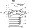
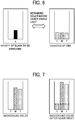
- FIG. 1 is a schematic cross-sectional view of an image forming apparatus 100 according to the first embodiment of the present disclosure.
- the image forming apparatus 100 serving as an image processing apparatus is a multifunction peripheral (MFP) having at least two of copying, printing, scanning, and facsimile functions.
- MFP multifunction peripheral
- the image forming apparatus 100 includes a sheet feeder 103, a housing 104, a scanner 101, and an automatic document feeder (ADF) 102.
- ADF automatic document feeder
- the image forming apparatus 100 includes a plotter 120 serving as an image forming device inside the housing 104.
- the plotter 120 includes a tandem image forming unit 105, a registration roller pair 108 that supplies the image forming unit 105 with a recording medium fed by the sheet feeder 103 through a conveyance passage 107, an optical writing device 109, a fixing device 110, and a duplex tray 111.
- drum-shaped photoconductors 112 are arranged side by side to form toner images of yellow (Y), magenta (M), cyan (C), and black (K), respectively.
- the black toner is an infrared absorbing visible toner.
- Each of the four photoconductors 112 is surrounded by various pieces of image forming equipment such as a charger, a developing device 106, a transfer device, a cleaner, and a neutralizer.
- An intermediate transfer belt 113 entrained around a drive roller and a driven roller, is disposed while being sandwiched between the four photoconductors 112 and the respective transfer devices.
- the scanner 101 reads a document image, which is an image of a document fed by the ADF 102, for example.
- the optical writing device 109 optically writes a latent image on the photoconductor 112 for each color of Y, M, C, and K according to data of the image.
- the developing device 106 develops the latent image into a toner image for each color.
- the toner images are primarily transferred onto the intermediate transfer belt 113 in the order of Y, M, C, and K, for example. Specifically, the toner images of the four colors are superimposed one atop another on the intermediate transfer belt 113 in a primary transfer process. Thus, a composite full-color toner image is formed on the intermediate transfer belt 113.
- the full-color toner image is secondarily transferred onto a recording medium supplied from the sheet feeder 103. Thereafter, the fixing device 110 fixes the full-color toner image onto the recording medium. Finally, the recording medium bearing the fixed toner image is ejected. Thus, the image forming apparatus 100 forms a full-color image on a recording medium.
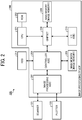
- FIG. 2 a description is given of a hardware configuration of the image forming apparatus 100 described above.
- FIG. 2 is a block diagram illustrating a hardware configuration of the image forming apparatus 100.
- the image forming apparatus 100 includes an image processing device 200 that processes a document image read by the scanner 101 and outputs the processed image as image data to the plotter 120.
- the scanner 101, the ADF 102, and the image processing device 200 construct a tilt correction device and a reading device.
- the image processing device 200 includes a central processing unit (CPU) 201, a read only memory (ROM) 202, a main memory 205, a chipset 206, an image processing application specific integrated circuit (ASIC) 207, a controller ASIC 208, a main memory 209, and an input/output (I/O) ASIC 210.
- the CPU 201 controls the image forming apparatus 100.
- the main memory 205 is a memory into which a program is loaded to cause the CPU 201 to control the image forming apparatus 100.
- the main memory 205 is used as a work area for the CPU 201.
- the main memory 205 is also used as an image memory to temporarily store image data to be handled.
- the chipset 206 is used together with the CPU 201 to control an access from the controller ASIC 208 and the I/O ASIC 210 to the main memory 205.
- the program executed by the image forming apparatus 100 may be stored in a computer- readable storage medium, such as a compact disc read-only memory (CD-ROM), a flexible disk (FD), a compact disc recordable (CD-R), and a digital versatile disk (DVD), in an installable or executable file format, to be provided.
- a computer- readable storage medium such as a compact disc read-only memory (CD-ROM), a flexible disk (FD), a compact disc recordable (CD-R), and a digital versatile disk (DVD)
- the program executed by the image forming apparatus 100 according to the present embodiment may be stored in a computer connected to a network such as the Internet and downloaded via the network, thus being providable.
- the program executed by the image forming apparatus 100 according to the present embodiment may be provided or distributed via a network such as the Internet.
- the scanner 101 has a function of reading image data to be copied or output to an external interface, for example.
- the plotter 120 has a function of printing image data stored in the main memory 209.
- the image processing ASIC 207 performs image processing on image data read by the scanner 101 and outputs the processed image data to the controller ASIC 208. In addition, the image processing ASIC 207 performs image processing on image data from the controller ASIC 208 to allow the plotter 120 to print the image data. According to print timing of the plotter 120, the image processing ASIC 207 transmits the processed image data to the plotter 120.
- the controller ASIC 208 uses the main memory 205 over the chipset 206 to rotate and edit image data handled by the image forming apparatus 100.
- the controller ASIC 208 stores the image data in a hard disk drive (HDD) 211.
- the controller ASIC 208 transmits and receives the image data to and from the image processing ASIC 207.
- the main memory 209 is used as an image memory with which the controller ASIC 208 performs image processing.
- the HDD 211 is used to temporarily store processed image data.
- the I/O ASIC 210 is an external interface that gives an additional function to the image forming apparatus 100.
- the I/O ASIC 210 includes interfaces such as a network interface, a universal serial bus (USB), a secure digital (SD) card, an operation unit, a serial peripheral interface (SPI), an inter-integrated circuit (I2C), and a document width sensor (or width detection sensor) interfaces, a hardware accelerator that accelerates image processing, and an encryption processing circuit.
- FIG. 3 is a functional block diagram of the image processing device 200 according to the first embodiment of the present disclosure.
- the image processing device 200 generally has a function of generating an image embedded with a latent image with four colorants including a black colorant exhibiting an infrared absorption characteristic and cyan, magenta, and yellow colorants each exhibiting an infrared transmission characteristic, by taking advantages of a color-matching masking effect and a visual masking effect that compensates for a defect of the color-matching masking effect in a mutually complementary manner.
- the plotter 120 prints the generated image that is embedded with the latent image, thereby producing a printed matter including an infrared latent image.
- the infrared latent image herein refers to image information that is difficult to be visually recognized under visible light and detectable simply by a sensing device having a reaction in infrared.
- An image embedded with a latent image described below refers to an image in which invisible information including an infrared latent image is embedded.
- a background image described below represents a visible image into which a latent image is embedded. When an image embedded with a latent image is viewed, the background image is viewed alone.
- a latent image described below refers to image information that is embedded as invisible information into the background image.
- a masking effect refers to a physical mask effect to conceal a latent image.
- Masking refers to image processing applied to a background to obtain the masking effect.
- the image processing device 200 includes a first masking unit 301, a second masking unit 302, and a latent image embedding unit 303.
- the first masking unit 301 serving as an auxiliary masking unit performs a first masking process to conceal a latent image.
- the first masking process refers to a process of changing a density change characteristic between pixels in an image to obtain a visual masking effect to conceal the latent image.
- the first masking process is herein referred to as a visual masking process.
- the first masking unit 301 serving as an auxiliary masking unit is configured to process a background image into which a latent image is embedded, to obtain an effect to conceal the latent image.
- the first masking unit 301 is configured to change a density change characteristic between pixels in the background image to obtain a visual masking effect to conceal the latent image.
- FIG. 26 is a diagram illustrating a way disclosed in JP-H07-319347-A , in which a specific pattern writing unit separates a background color of image information to extract color components and determines an appropriate density based on the extracted color components.
- the specific pattern writing unit separates the background color of the image information received from a scanner into YMC color components and extracts a black component (hatched by diagonal lines in graph 1 of FIG. 26 ).
- the specific pattern writing unit separates the background color of the image information to extract the color components and determines an appropriate density based on the extracted color components. Accordingly, a specific pattern is added in an inconspicuous manner without deteriorating the color reproducibility of a copy. In addition, the detection accuracy is increased to reliably track the copy.
- the first masking unit 301 synthesizes a specific masking pattern and a background image into which a latent image is embedded, so as to prevent visualization of the latent image.
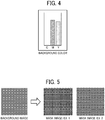
- FIG. 4 is a diagram illustrating an example of the background image, as a target background image, into which a latent image is embedded.
- the target background image is not a gray image entirely constructed of cyan, magenta, and yellow.
- a background color component of the target background image a reddish color represented by magenta and yellow values is used. That is, the target background image does not include a cyan component. In other words, the target background image is formed with colors that do not include a gray component.
- FIG. 5 is a diagram illustrating an example of the first masking process.
- a grid waveform is an example of a specific masking pattern.
- the first masking unit 301 synthesizes the specific masking pattern and a target background image into which a latent image is embedded.
- the pattern type and intensity is desirably changed according to the spatial frequency characteristics of the background image and the latent image. For example, a user or an administrator may select any pattern type and intensity from a plurality of pattern types and intensities. In addition to the changes to pattern, aperiodic noise may be added. A detailed description is deferred of how to select and adjust the pattern.
- the second masking unit 302 serving as a color-matching masking unit performs a second masking process to conceal a latent image.
- the second masking process refers to a process of performing color conversion to enhance a color-matching masking effect to conceal a latent image.
- the second masking process is herein referred to as a color-matching masking process.
- the color-matching masking effect is defined as an effect of concealing a latent image in a background by taking an advantage of a masking effect from the metamerism.
- the second masking unit 302 serving as a color-matching masking unit is configured to perform color conversion of the background image to obtain a color-matching masking effect to conceal the latent image.
- FIG. 6 is a diagram illustrating a relationship between a density of black to be embedded and cyan, magenta, and yellow (CMY) amounts (or densities) to be added.
- Embedding an infrared pattern using black toner as in the technique disclosed in JP-H07-319347-A uses a gray component (i.e., CMY components) corresponding to the density of the black to be embedded as illustrated in FIG. 6 .
- CMY components a gray component corresponding to the density of the black to be embedded
- the color tones do not metamerically match before and after the CMY-to-CMYK conversion, rendering the latent image visible.
- FIG. 7 is a diagram illustrating an example of the second masking process.
- the second masking unit 302 adds the gray component corresponding to a density value of the black to be embedded, to attain a metameric color match before and after an embedding process.
- the second masking unit 302 serving as a color-matching masking unit is configured to add a gray component as color conversion of a background image.
- the CMY values are desirably used that metamerically match black having a predetermined density and used for embedment.
- FIG. 8 is a diagram illustrating an amount of gray added in the color-matching masking process.
- FIG. 9 is a reference table illustrating a relationship between an amount of black to be embedded and corresponding print amounts of CMY-gray, that is, cyan, magenta, and yellow (CMY) that generate gray.
- FIG. 6 illustrates CMY-gray as a metamer of K-gray.
- the CMY-gray is generated by printing C, M, and Y in equal amount.
- the K-gray is generated by K component. Since the combination of CMY as a metamer of the K-gray differs depending on the characteristics of colorants used in the image forming apparatus 100, the combination of CMY is preferably determined according to the characteristic of the image forming apparatus 100. In other words, the conditions for metamerism depend on the characteristics of printing devices.
- FIG. 8 illustrates 3C gray as a metamer of the K-gray in the image forming apparatus 100.
- K 20%
- appropriate percentages of C, M, and Y are 23%, 19%, and 17%, respectively, to generate the 3C gray as a metamer of the K-gray under a D50 light source.
- the CMY amounts corresponding to the maximum print amount of K used for embedment, the color-matching masking process can be performed on any background color.
- FIG. 9 illustrates a metameric relationship between various print amounts of K and the respective print amounts of C, M, and Y in the image forming apparatus 100. Retaining the CMY amounts corresponding to the print amount of K as a reference table as illustrated in FIG. 9 allows determination of an amount of gray to be added appropriate for a variable density of a latent image to be embedded. Note that, in the present embodiment, the reference table illustrated in FIG. 9 is used for adding gray. Alternatively, the reference table may be used for adding K and reducing C, M, and Y.
- the amount of gray to be added is automatically determined with reference to the table illustrated in FIG. 9 .
- a user may adjust the amount of gray to be added, in consideration of the design or designability.
- a user who is concerned about the graying of a background rather than the stealth may not necessarily add the gray component corresponding to the maximum density.
- the gray component may be manually adjustable by, e.g., a user.
- masking processes are performed in combination, such as the first masking process to obtain a visual masking effect and the second masking process to obtain a masking effect from the metamerism.
- the first masking unit 301 and the second masking unit 302 generate a masked background image subjected to the first masking process and the second masking process to conceal a latent image with enhanced confidentiality.
- the latent image embedding unit 303 performs a latent image synthesizing process of embedding a designated latent image in the masked background image generated by the first masking unit 301 and the second masking unit 302 to generate an image embedded with the latent image.
- the latent image embedding unit 303 is configured to embed the latent image in the background image processed by the first masking unit 301 serving as an auxiliary masking unit and converted by the second masking unit 302 serving as a color-matching masking unit, to generate an image embedded with the latent image.
- the latent image information is preferably image information designated with the K plane.
- the latent image embedding unit 303 changes an amount of generation of a black component according to the pixel value of the latent image, thereby embedding the latent image.
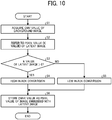
- FIG. 10 is a schematic flowchart of the latent image embedding process.
- the latent image embedding unit 303 performs the following process on all pixel values in a masked background image.
- step S1 the latent image embedding unit 303 acquires a pixel value (as a CMY value) of the masked background image generated by the first masking unit 301 and the second masking unit 302.
- the latent image embedding unit 303 refers to a pixel value of a latent image at a pixel position identical to a position of a reference pixel of the masked background image.
- the latent image embedding unit 303 refers to K-plate information (i.e., K value) as the latent image is formed by the K plate.
- the latent image is binarized.
- step S3 the latent image embedding unit 303 determines whether the pixel value (i.e., K value) of the latent image is greater than 0 (i.e., K > 0).
- the latent image embedding unit 303 determines that the pixel value (i.e., K value) of the latent image is greater than 0 (YES in step S3), that is, when the pixel is a black pixel, the latent image embedding unit 303 performs high black conversion to replace the CMY value with K in step S4.
- decreased CMY amounts are adjusted in the CMY-to-CMYK conversion such that the color tone (e.g., Lab) does not theoretically change under visible light at the time of conversion, in other words, such that the color tone before conversion and the color tone after conversion metamerically match.
- the latent image embedding unit 303 may perform low black conversion to generate K in less amount than the amount of K generated when the pixel value (i.e., K value) of the latent image is greater than 0. Note that, even in a case in which the latent image embedding unit 303 performs the low black conversion, the CMY-to-CMYK conversion is adjusted such that the color tones metamerically match before and after the conversion.
- step S6 the latent image embedding unit 303 newly stores the CMYK amount (i.e., CMYK value) generated in step S4 or step S5 as a pixel value of an image embedded with the latent image.
- CMYK amount i.e., CMYK value
- the latent image embedding unit 303 repeats the processing of steps S1 to S6 on all the pixels of the masked background image to generate a new image embedded with the latent image. Since the color tone is herein adjusted not to change under visible light at the time of CMY-to-CMYK conversion, the image embedded with the latent image and the masked background image do not change visually when the images are output. However, in the image embedded with the latent image, the generated amount of K differs for each pixel depending on the pixel values of the latent image.
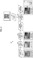
- FIGS. 11A and 11B illustrate a difference between a visual image and an infrared image of a printed matter produced by printing an infrared latent image generated by the image processing device 200.
- FIG. 11A is a diagram illustrating a latent image and an image embedded with the latent image.
- FIG. 11B is a diagram illustrating the difference between the visual image and the infrared image of the printed image embedded with the latent image.
- FIG. 11A illustrates an example in which a binary image storing a Quick Response (QR) code (registered trademark) is embedded as a latent image in a uniform background image subjected to the first masking process and the second masking process.
- QR Quick Response
- K is generated according to the characteristic amount of the QR code as illustrated in FIG. 11A .
- the image forming apparatus 100 prints the image embedded with the latent image with CMYK toners to faithfully reproduce the pixel values of the image embedded with the latent image, the masked background image is viewed as illustrated in FIG. 11B .
- CMY toners are transparent because the CMY toners have a transmission characteristic; whereas K toner appears black because the K toner has an absorption characteristic. Therefore, the QR code embedded as a latent image can be confirmed with the infrared sensing device.
- color tones of a background image metamerically match before and after the CMY-to-CMYK conversion is performed to embed a latent image in the background image, even in a case in which the background image does not include a gray component and therefore the technique disclosed in JP-H07-319347-A fails to satisfy the metamerism.
- the color-matching masking effect prevents visualization of the latent image.
- the visual masking process as the first masking process generates a change in shading in the background image, which is originally in a uniform color.
- the visual masking process provides a visual masking effect. Accordingly, even in a case in which the conditions for metamerism change due to density fluctuations or changes in viewing circumstance, the present embodiment prevents visualization of the latent image.
- the color-matching masking process is performed after the visual masking process.
- the visual masking process is performed after the color-matching process
- changes in shading resulting from the visual masking process may cause the conditions for metamerism collapse.
- the color-matching masking process is performed after the visual masking process in the present embodiment.
- the color-matching masking process is desirably performed as a last process.
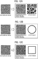
- FIGS. 12A to 12C a description is given of how to select a mask pattern (or spatial pattern) to be added in the visual masking process according to an attribute of a latent image.
- FIGS. 12A to 12C illustrate some examples of a mask pattern selected according to attributes of latent images.
- FIG. 12A is a diagram illustrating a first example of the mask pattern selected according to an attribute of a latent image.
- FIG. 12B is a diagram illustrating a second example of the mask pattern selected according to an attribute of another latent image.
- FIG. 12C is a diagram illustrating a third example of the mask pattern selected according to an attribute of yet another latent image.
- FIGS. 12A to 12C illustrate different types of mask pattern to be added, according to the attributes of the latent images.
- the first masking unit 301 serving as an auxiliary masking unit is configured to synthesize a spatial pattern and a background image into which a latent image is embedded.
- the first masking unit 301 is configured to select one type of the spatial pattern from a plurality of types of the spatial pattern according to an attribute of the latent image.
- One approach to concealing a latent image involves a mask pattern having a characteristic similar to a typical characteristic of the latent image, because such a mask pattern makes it difficult to visually distinguish between the mask pattern and the latent image and prevents visualization of the latent image.
- FIG. 12A illustrates a mask pattern suitable for embedding a QR code as a latent image.
- a mask pattern in a grid waveform is desirably used in which the positional information (X, Y) of the image is indicative of the phase information.
- the spatial pattern is a grid pattern having coordinate information as phase information.
- FIG. 12B illustrates a mask pattern suitable for embedding a circular mark as a latent image.
- typical graphic shapes such as circles, triangles, and quadrangles remain as memory shapes in the human brain and are easily recognized. Therefore, a slight change in density of a latent image in such a shape may facilitate visual recognition of the latent image.
- FIG. 12B illustrates a spherical wave pattern to be added as a visual masking pattern so as to prevent visualization of the circular mark.
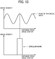
- the spatial pattern is a spherical wave pattern having a distance from a specific position as phase information. The distance from a specific position is, e.g., a distance from an image center as illustrated in FIG. 13 .
- FIG. 13 is a graph illustrating how to adjust the phase of a mask pattern.
- the phase of the mask pattern is adjusted so as to superimpose a peak of the spherical wave increased in density atop a black portion of the circular mark.
- the circular portion is visually mixed with the spherical wave that causes the density fluctuations.
- the present example further reduces the visibility of the latent image and enhances the stealth.
- FIG. 12C illustrates a wave-front pattern in which a square wave radially spreads from the center, as a mask pattern for visual masking to conceal a quadrangular latent image.
- the spatial pattern is a quadrangular or rectangular wave pattern.
- a peak of the wave front is superimposed atop the quadrangular latent image to prevent visualization of the latent image.
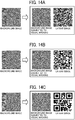
- FIGS. 14A to 14C illustrate some frequency examples of a mask pattern selected according to attributes of latent images.
- FIG. 14A is a diagram illustrating a first frequency example of a mask pattern selected according to an attribute of a latent image.
- FIG. 14B is a diagram illustrating a second frequency example of the mask pattern selected according to an attribute of another latent image.
- FIG. 14C is a diagram illustrating a third frequency example of the mask pattern selected according to an attribute of yet another latent image.
- FIGS. 14A to 14C illustrate how to adjust the cycle of a visual mask pattern in a case in which a QR code is embedded as a latent image.
- a code having a relatively small minimum cell and a relatively high spatial frequency is synthesized with a dense pattern having a relatively high spatial frequency as a visual mask pattern.
- a code having a relatively large minimum cell and a relatively low spatial frequency is synthesized with a pattern having a relatively low frequency as a visual mask pattern.
- the density cycle of the visual mask pattern is preferably matched with a print cycle of the cell size of the QR code. This is because signals having closer spatial frequencies are harder for humans to separately recognize as different signals, thus effectively preventing visualization of the latent image.
- a computer may automatically select the type of spatial pattern and adjust the phase based on an attribute of a background image as described above.
- a user for example, may manually select the type of spatial pattern and adjust the phase with reference to the aforementioned rules relative to the latent image.
- the first masking unit 301 serving as an auxiliary masking unit is configured to determine one of a period and amplitude information of the spatial pattern according to an attribute of the latent image.
- one of a period and amplitude information of the spatial pattern may be manually changeable by, e.g., a user.
- a spatial pattern synthesized with a background image as described above provides a visual masking effect, even in a case in which the background image is a flat image without a portion having great density fluctuations and hampers visual masking.
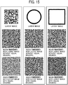
- FIG. 15 is a diagram illustrating some examples of effects resulting from visual masking.
- FIG. 15 illustrates latent images in the upper row and images embedded with latent images in the middle and lower rows.
- FIG. 15 illustrates, in the middle row, the images in which the latent images in the upper row are embedded in uniform background images, respectively.
- FIG. 15 illustrates, in the lower row, the images in which the latent images in the upper row are embedded in the background images to which visual masking patterns are added, respectively.
- the latent images are visualized on the uniform background images, respectively, because the conditions for metamerism are not satisfied at the time of image formation due to changes in viewing circumstance or the density fluctuations of device.
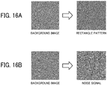
- FIGS. 16A and 16B illustrate other examples of the visual masking pattern.
- FIGS. 14A to 14C a description is given above of a grid pattern formed in a two-dimensional sine wave to mask a QR code.
- a rectangle pattern as illustrated in FIG. 16A may be used.
- the grid pattern as illustrated in FIGS. 14A to 14C and the rectangle pattern as illustrated in FIG. 16A may be selected by, e.g., a user in consideration of the designability.
- a background image may be synthesized with an aperiodic noise signal, as illustrated in FIG. 16B , as a visual masking pattern.
- the spatial pattern is an aperiodic noise signal.
- Such an aperiodic signal has a relatively high affinity with any latent image shape. Adjustment of the period and the amount of noise of the aperiodic signal maintains the designability of the background image.
- a latent image in a technique of embedding an infrared latent image by a combination of visible colorants having different optical characteristics such as cyan, magenta, yellow, and black, a latent image is concealed by taking advantages of the color-matching masking effect and the visual masking effect that compensates for the defect of the color-matching masking effect in a mutually complementary manner. Accordingly, an enhanced stealth or confidential latent image is formed.
- the visual masking effect and the color-matching masking effect are described as examples. Advantages of other different masking effects may be taken in combination depending on the properties of the background image and the latent image.
- the first masking unit 301 adds a visual masking pattern to a background image in the first masking process.
- the second masking unit 302 adds a gray component in the second masking process.
- an original background image includes a portion exhibiting a visual masking effect, such as a portion having a high contract, and a portion having a sufficient gray component and exhibiting a color-matching masking effect
- the background image may not be subjected to the masking processes described above.
- the background image is segmented so that the visual masking effect and the color-matching masking effect are determined for each segment to search, in the background image, a portion in which an enhanced stealth latent image can be embedded.
- an enhanced stealth latent image is embedded by taking advantages of multiple masking effects such as the visual masking effect and the color-matching effect complementarily, without processing the background image as in the first embodiment.
- FIG. 17 is a functional block diagram of an image processing device 200A according to the second embodiment of the present disclosure.
- the image processing device 200A includes a first masking effect determining unit 311, a second masking effect determining unit 312, the latent image embedding unit 303, a segmenting unit 304, a candidate segment determining unit 305, an embedment background image extracting unit 306, and a background image synthesizing unit 307.
- the segmenting unit 304 segments a background image into which a latent image is embedded.
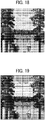
- FIG. 18 is a diagram illustrating an example of the background image.
- the background image of the present embodiment is a mixture of a portion having a high contrast and a portion having a relatively low contrast.
- the gray component may be present or absent depending on the segments of the background image.
- FIG. 19 is a diagram illustrating an example of segmentation of the background image.
- the segmenting unit 304 segments the background image in a grid pattern. Note that the segmenting unit 304 may adjust the segment position for each user, instead of fixing the segment position.
- the segmenting unit 304 outputs the segmented background image to the first masking effect determining unit 311.
- the first masking effect determining unit 311 serving as an auxiliary masking effect determining unit determines, for each segment of the background image, a visual masking degree that indicates the effectiveness of visual masking.
- FIG. 20 is a diagram illustrating an example of determination of the visual masking degree for the background image segmented as illustrated in FIG. 19 .
- the visual masking degree is determined as "large” when the segment of the background image includes a relatively large number of components contrasting sharply in shading.
- the visual masking degree is determined as "small” when the segment of the background image includes a relatively small number of components contrasting sharply in shading.
- Such determination may be made based on a histogram distribution.
- a pixel histogram distribution indicates a relatively large degree of dispersion
- the segment of the background image includes pixels in a plurality of colors and has a relatively high contrast.
- the pixel histogram distribution indicates a relatively small degree of dispersion
- the segment of the background image includes uniform pixels that construct a flat image.
- the visual masking degree is determined based on whether or not the segment of the background image includes, among the spatial frequency components that construct a latent image, a relatively large amount of main spatial frequency component (i.e., spatial frequency component of the latent image).
- the second way of determination is effective because the spatial frequency components of a background image close to the spatial frequency components of a latent image make it hard for human vision to separate signals, thus facilitating concealment of the latent image.
- a user visually determines whether an image in a segment has the contrast and subjectively evaluates the visual masking degree.
- the second masking effect determining unit 312 serving as a color-matching masking effect determining unit determines, for each segment of the background image, a color-matching masking degree that indicates the effectiveness of color-matching masking.
- FIG. 21 is a diagram illustrating an example of determination of the color-matching masking degree for the background image segmented as illustrated in FIG. 19 .
- the color-matching masking degree is determined by analyzing pixel values such as red-green-blue (RGB) values or CMY values in a segment of the background image.
- the second masking unit 302 analyzes the gray component in an RGB value or a CMY value.
- the RGB signal may be converted into a hue-saturation-value (HSV) signal.
- the gray component may be determined by a value of saturation (S).
- the gray component of an entire segment may be temporarily determined as a gray component for an average value of all the pixels of the segment.
- the gray component of the entire segment may be determined by counting pixel values having a predetermined gray component or greater.
- the color-matching masking degree is determined according to the amount of the gray component for each segment.
- a user may visually determine the saturation of an image in a segment and subjectively evaluate the color-matching masking degree.
- the candidate segment determining unit 305 determines a candidate segment in which a latent image is embeddable or can be embedded, based on determination results of the visual masking degree and the color-matching masking degree.
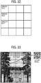
- FIG. 22 is a diagram illustrating an example of determination of the candidate segment.
- the candidate segment determining unit 305 determines, as a candidate segment, a segment for which both the visual masking degree and the color-matching masking degree are determined as "large”. Note that this way of determination is adjustable as appropriate for the density of black used for embedment or the characteristics of the image forming apparatus 100.
- the embedment background image extracting unit 306 selects or determines a target segment for embedding a latent image from candidate segments and extracts the selected segment (i.e., image area).
- FIG. 23 is a diagram illustrating an example of determination of the target segment.
- FIG. 24 is a diagram illustrating the target segment extracted.
- a user in a case in which plural candidate segments are determined as illustrated in FIG. 22 , a user, for example, can select any one of the plural candidate segments. As a consequence, according to the purpose, the user can embed a latent image in any segment selected from the candidate segments automatically calculated.
- the latent image embedding unit 303 performs a latent image synthesizing process of embedding a specified latent image in the extracted target segment (or target image area) to generate an image embedded with the latent image.
- FIG. 25 is a diagram illustrating an example of the image embedded with the latent image.
- the background image synthesizing unit 307 performs a process of synthesizing the generated image embedded with the latent image and the segment or area, from which the target segment is extracted, of the background image.
- a segment from which great visual masking effect and color-matching masking effect are obtained is determined in a background image. According to the determination result, a latent image is embedded in the determined segment. Accordingly, an enhanced stealth infrared latent image is formed by taking advantages of the visual masking effect and the color-matching masking effect.
- a pattern can be added in the visual masking process to address a small visual masking degree; whereas, to address a small color-matching masking degree, the color-matching masking process is performed on an image to turn a segment in which a latent image is unable to be embedded into a segment in which a latent image is able to be embedded.
- the image processing devices 200 and 200A are applied to the image forming apparatus 100, which is an MFP having at least two of copying, printing, scanning, and facsimile functions.
- the image forming apparatus 100 may be, e.g., a copier, a printer, a scanner, or a facsimile machine.
- An information processing device such as a print server or a client personal computer (PC) may be applied as the image processing device 200 or 200A described above.
- the information processing device includes a CPU that operates according to an installed program, thereby performing substantially the same function as the function of the image processing device 200 or 200A to generate an image embedded with a latent image.
- the image forming apparatus 100 having a printing function prints image data including the image embedded with the latent image, which is generated by the information processing device, thereby producing a printed matter including an infrared latent image.
- the processing units illustrated in FIGS. 3 and 17 are not necessarily arranged in the same image processing device or information processing device.
- the first masking unit 301 may be implemented by an information processing device such as a print server or a client PC.
- the second masking unit 302 may be implemented by an image processing apparatus such as an MFP or a printer.
- the present invention can be implemented in any convenient form, for example using dedicated hardware, or a mixture of dedicated hardware and software.
- the present invention may be implemented as computer software implemented by one or more networked processing apparatuses.
- the processing apparatuses can include any suitably programmed apparatuses such as a general-purpose computer, personal digital assistant, mobile telephone (such as a WAP or 3G-compliant phone) and so on. Since the present invention can be implemented as software, each and every aspect of the present invention thus encompasses computer software implementable on a programmable device.
- the computer software can be provided to the programmable device using any conventional carrier medium (carrier means).
- the carrier medium can include a transient carrier medium such as an electrical, optical, microwave, acoustic or radio frequency signal carrying the computer code.
- transient medium is a TCP/IP signal carrying computer code over an IP network, such as the Internet.
- the carrier medium can also comprise a storage medium for storing processor readable code such as a floppy disk, hard disk, CD ROM, magnetic tape device or solid-state memory device.
Landscapes
- Engineering & Computer Science (AREA)
- Multimedia (AREA)
- Signal Processing (AREA)
- Theoretical Computer Science (AREA)
- Physics & Mathematics (AREA)
- General Physics & Mathematics (AREA)
- Human Computer Interaction (AREA)
- General Engineering & Computer Science (AREA)
- Quality & Reliability (AREA)
- Image Processing (AREA)
- Editing Of Facsimile Originals (AREA)
- Accessory Devices And Overall Control Thereof (AREA)
- Record Information Processing For Printing (AREA)
- Control Or Security For Electrophotography (AREA)
- Color Electrophotography (AREA)
Applications Claiming Priority (1)
| Application Number | Priority Date | Filing Date | Title |
|---|---|---|---|
| JP2019117945A JP7293908B2 (ja) | 2019-06-25 | 2019-06-25 | 画像処理装置、プログラムおよび潜像埋め込み方法 |
Publications (2)
| Publication Number | Publication Date |
|---|---|
| EP3756900A1 true EP3756900A1 (de) | 2020-12-30 |
| EP3756900B1 EP3756900B1 (de) | 2025-04-23 |
Family
ID=71120078
Family Applications (1)
| Application Number | Title | Priority Date | Filing Date |
|---|---|---|---|
| EP20181372.2A Active EP3756900B1 (de) | 2019-06-25 | 2020-06-22 | Bildverarbeitungsvorrichtung, verfahren zum einbetten eines latenten bildes und trägermedium |
Country Status (4)
| Country | Link |
|---|---|
| US (1) | US11431877B2 (de) |
| EP (1) | EP3756900B1 (de) |
| JP (1) | JP7293908B2 (de) |
| CN (1) | CN112135006B (de) |
Families Citing this family (4)
| Publication number | Priority date | Publication date | Assignee | Title |
|---|---|---|---|---|
| JP7559397B2 (ja) | 2020-07-22 | 2024-10-02 | 株式会社リコー | 情報処理装置およびプログラム |
| JP7769901B2 (ja) * | 2021-10-11 | 2025-11-14 | 株式会社リコー | 印刷物及び画像形成装置 |
| JP2024173512A (ja) | 2023-06-02 | 2024-12-12 | 株式会社リコー | 印刷システム、印刷方法およびプログラム |
| TWI873867B (zh) * | 2023-09-22 | 2025-02-21 | 虹光精密工業股份有限公司 | 產生含有透明度及可見光資訊的影像檔的掃描裝置 |
Citations (5)
| Publication number | Priority date | Publication date | Assignee | Title |
|---|---|---|---|---|
| JPH07319347A (ja) | 1994-05-27 | 1995-12-08 | Ricoh Co Ltd | 画像形成装置 |
| US20070262579A1 (en) * | 2006-05-11 | 2007-11-15 | Xerox Corporation | Substrate fluorescence pattern mask for embedding information in printed documents |
| EP1961577A2 (de) * | 2007-02-20 | 2008-08-27 | Xerox Corporation | Substratfluoreszenz-Maske und Herstellungsverfahren |
| US20080304696A1 (en) * | 2007-06-05 | 2008-12-11 | Xerox Corporation | Infrared encoding for embedding multiple variable data information collocated in printed documents |
| US20100157377A1 (en) * | 2008-12-18 | 2010-06-24 | Xerox Corporation | Uv fluorescence encoded background images using adaptive halftoning into disjoint sets |
Family Cites Families (18)
| Publication number | Priority date | Publication date | Assignee | Title |
|---|---|---|---|---|
| JP3484677B2 (ja) | 1997-01-08 | 2004-01-06 | 株式会社リコー | 画像形成装置 |
| JPH10312487A (ja) * | 1997-05-14 | 1998-11-24 | Kyodo Printing Co Ltd | 磁気カード及びその真偽判別方法 |
| US6993149B2 (en) * | 2001-09-25 | 2006-01-31 | Digimarc Corporation | Embedding digital watermarks in spot colors |
| US6804377B2 (en) * | 2000-04-19 | 2004-10-12 | Digimarc Corporation | Detecting information hidden out-of-phase in color channels |
| JP4656719B2 (ja) | 2000-11-27 | 2011-03-23 | 小林クリエイト株式会社 | 偽造防止帳票 |
| JP4620280B2 (ja) | 2001-04-16 | 2011-01-26 | 大日本印刷株式会社 | 真正性の判別可能なカード |
| US20050058476A1 (en) * | 2003-09-17 | 2005-03-17 | Canon Kabushiki Kaisha | Copy-forgery-inhibited pattern density parameter determination method, copy-forgery-inhibited pattern image generation method, and image processing apparatus |
| JP2005170007A (ja) | 2003-12-15 | 2005-06-30 | Seiko Epson Corp | 記録装置、記録方法、およびプログラム |
| JP4290681B2 (ja) * | 2005-06-30 | 2009-07-08 | シャープ株式会社 | 画像処理装置、画像処理方法、画像処理プログラム、画像処理プログラムを記録した機械読取可能な記録媒体および印刷物 |
| JP4991377B2 (ja) | 2007-04-19 | 2012-08-01 | キヤノン株式会社 | 画像形成装置 |
| US8705142B2 (en) * | 2007-06-18 | 2014-04-22 | Seiko Epson Corporation | Tint block image generation program, tint block image generation device, and tint block image generation method |
| JP5304529B2 (ja) | 2009-08-17 | 2013-10-02 | 富士ゼロックス株式会社 | 画像処理装置及び画像処理プログラム |
| US9092872B2 (en) * | 2010-10-11 | 2015-07-28 | Graphic Security Systems Corporation | System and method for creating an animation from a plurality of latent images encoded into a visible image |
| JP5891746B2 (ja) | 2011-11-28 | 2016-03-23 | 株式会社リコー | 画像処理装置、画像処理方法、及びプログラム |
| JP6111677B2 (ja) * | 2012-03-23 | 2017-04-12 | 株式会社リコー | 情報処理装置、画像生成方法及び画像生成プログラム |
| JP6305043B2 (ja) | 2013-12-06 | 2018-04-04 | 共同印刷株式会社 | 識別コード付き印刷物 |
| JP2016190479A (ja) | 2015-03-30 | 2016-11-10 | ケイディケイ株式会社 | 情報通信体 |
| JP2017183781A (ja) | 2016-03-28 | 2017-10-05 | 理想科学工業株式会社 | 画像データ生成装置及び画像形成装置 |
-
2019
- 2019-06-25 JP JP2019117945A patent/JP7293908B2/ja active Active
-
2020
- 2020-06-18 CN CN202010562689.2A patent/CN112135006B/zh active Active
- 2020-06-22 EP EP20181372.2A patent/EP3756900B1/de active Active
- 2020-06-23 US US16/908,764 patent/US11431877B2/en active Active
Patent Citations (5)
| Publication number | Priority date | Publication date | Assignee | Title |
|---|---|---|---|---|
| JPH07319347A (ja) | 1994-05-27 | 1995-12-08 | Ricoh Co Ltd | 画像形成装置 |
| US20070262579A1 (en) * | 2006-05-11 | 2007-11-15 | Xerox Corporation | Substrate fluorescence pattern mask for embedding information in printed documents |
| EP1961577A2 (de) * | 2007-02-20 | 2008-08-27 | Xerox Corporation | Substratfluoreszenz-Maske und Herstellungsverfahren |
| US20080304696A1 (en) * | 2007-06-05 | 2008-12-11 | Xerox Corporation | Infrared encoding for embedding multiple variable data information collocated in printed documents |
| US20100157377A1 (en) * | 2008-12-18 | 2010-06-24 | Xerox Corporation | Uv fluorescence encoded background images using adaptive halftoning into disjoint sets |
Also Published As
| Publication number | Publication date |
|---|---|
| EP3756900B1 (de) | 2025-04-23 |
| CN112135006B (zh) | 2022-11-15 |
| US20200412916A1 (en) | 2020-12-31 |
| CN112135006A (zh) | 2020-12-25 |
| US11431877B2 (en) | 2022-08-30 |
| JP7293908B2 (ja) | 2023-06-20 |
| JP2021004957A (ja) | 2021-01-14 |
Similar Documents
| Publication | Publication Date | Title |
|---|---|---|
| EP3756900B1 (de) | Bildverarbeitungsvorrichtung, verfahren zum einbetten eines latenten bildes und trägermedium | |
| US7509060B2 (en) | Density determination method, image forming apparatus, and image processing system | |
| JP3599795B2 (ja) | 画像処理装置 | |
| US7599099B2 (en) | Image processing apparatus and image processing method | |
| JP2008219888A (ja) | デジタル画像処理方法およびデジタル画像処理システム | |
| EP3758350B1 (de) | Bildverarbeitungsvorrichtung, drucksystem, verfahren zum einbetten eines latenten bildes und trägermedium | |
| EP0999522A2 (de) | Bildverarbeitungsverfahren, -system und -gerät, und Speichermedium | |
| US5933256A (en) | Method for color correction within a color space using hue shifting of a region therein | |
| CN102547052A (zh) | 图像处理装置、图像形成装置和图像处理方法 | |
| US5953499A (en) | Color printing hue rotation system | |
| US7599081B2 (en) | Detecting and protecting a copy guarded document | |
| US20100157350A1 (en) | Image processing apparatus and image processing method | |
| EP2144430B1 (de) | Bildverarbeitungsvorrichtung und Bildverarbeitungsverfahren | |
| US6469806B1 (en) | Method and apparatus for reducing excess developer material at the edges of print sheets of full bleed images via digital image processing | |
| CN102555560B (zh) | 图像处理装置、图像形成装置以及图像处理方法 | |
| JP4653006B2 (ja) | 潜像画像、背景画像の濃度信号値を決定する方法及び装置及びプログラム | |
| JP5454258B2 (ja) | 情報処理装置、画像処理システム、及びプログラム | |
| JP2022170951A (ja) | 画像処理装置、画像形成装置および画像処理方法 | |
| JP2016025420A (ja) | 画像処理装置、画像処理方法、及びプログラム | |
| JP2015220580A (ja) | 画像処理装置、画像処理方法及びプログラム。 | |
| JP2025124016A (ja) | 画像処理装置、画像処理方法およびプログラム | |
| JP2025124017A (ja) | 画像処理装置、画像処理方法及びプログラム | |
| JP2022019769A (ja) | 画像処理装置、画像形成装置およびプログラム | |
| JP2008205906A (ja) | 画像形成装置、画像処理装置及び画像形成方法 | |
| JP2001189842A (ja) | 画像処理装置および画像処理方法 |
Legal Events
| Date | Code | Title | Description |
|---|---|---|---|
| PUAI | Public reference made under article 153(3) epc to a published international application that has entered the european phase |
Free format text: ORIGINAL CODE: 0009012 |
|
| STAA | Information on the status of an ep patent application or granted ep patent |
Free format text: STATUS: REQUEST FOR EXAMINATION WAS MADE |
|
| 17P | Request for examination filed |
Effective date: 20200622 |
|
| AK | Designated contracting states |
Kind code of ref document: A1 Designated state(s): AL AT BE BG CH CY CZ DE DK EE ES FI FR GB GR HR HU IE IS IT LI LT LU LV MC MK MT NL NO PL PT RO RS SE SI SK SM TR |
|
| AX | Request for extension of the european patent |
Extension state: BA ME |
|
| STAA | Information on the status of an ep patent application or granted ep patent |
Free format text: STATUS: EXAMINATION IS IN PROGRESS |
|
| 17Q | First examination report despatched |
Effective date: 20230228 |
|
| GRAP | Despatch of communication of intention to grant a patent |
Free format text: ORIGINAL CODE: EPIDOSNIGR1 |
|
| STAA | Information on the status of an ep patent application or granted ep patent |
Free format text: STATUS: GRANT OF PATENT IS INTENDED |
|
| INTG | Intention to grant announced |
Effective date: 20241121 |
|
| GRAS | Grant fee paid |
Free format text: ORIGINAL CODE: EPIDOSNIGR3 |
|
| GRAA | (expected) grant |
Free format text: ORIGINAL CODE: 0009210 |
|
| STAA | Information on the status of an ep patent application or granted ep patent |
Free format text: STATUS: THE PATENT HAS BEEN GRANTED |
|
| AK | Designated contracting states |
Kind code of ref document: B1 Designated state(s): AL AT BE BG CH CY CZ DE DK EE ES FI FR GB GR HR HU IE IS IT LI LT LU LV MC MK MT NL NO PL PT RO RS SE SI SK SM TR |
|
| P01 | Opt-out of the competence of the unified patent court (upc) registered |
Free format text: CASE NUMBER: APP_13042/2025 Effective date: 20250317 |
|
| REG | Reference to a national code |
Ref country code: GB Ref legal event code: FG4D |
|
| REG | Reference to a national code |
Ref country code: CH Ref legal event code: EP |
|
| REG | Reference to a national code |
Ref country code: DE Ref legal event code: R096 Ref document number: 602020049833 Country of ref document: DE |
|
| REG | Reference to a national code |
Ref country code: IE Ref legal event code: FG4D |
|
| PGFP | Annual fee paid to national office [announced via postgrant information from national office to epo] |
Ref country code: DE Payment date: 20250618 Year of fee payment: 6 |
|
| REG | Reference to a national code |
Ref country code: NL Ref legal event code: FP |
|
| PGFP | Annual fee paid to national office [announced via postgrant information from national office to epo] |
Ref country code: GB Payment date: 20250618 Year of fee payment: 6 |
|
| PGFP | Annual fee paid to national office [announced via postgrant information from national office to epo] |
Ref country code: NL Payment date: 20250618 Year of fee payment: 6 |
|
| PGFP | Annual fee paid to national office [announced via postgrant information from national office to epo] |
Ref country code: FR Payment date: 20250626 Year of fee payment: 6 |
|
| REG | Reference to a national code |
Ref country code: AT Ref legal event code: MK05 Ref document number: 1787431 Country of ref document: AT Kind code of ref document: T Effective date: 20250423 |
|
| PG25 | Lapsed in a contracting state [announced via postgrant information from national office to epo] |
Ref country code: ES Free format text: LAPSE BECAUSE OF FAILURE TO SUBMIT A TRANSLATION OF THE DESCRIPTION OR TO PAY THE FEE WITHIN THE PRESCRIBED TIME-LIMIT Effective date: 20250423 Ref country code: PT Free format text: LAPSE BECAUSE OF FAILURE TO SUBMIT A TRANSLATION OF THE DESCRIPTION OR TO PAY THE FEE WITHIN THE PRESCRIBED TIME-LIMIT Effective date: 20250825 Ref country code: FI Free format text: LAPSE BECAUSE OF FAILURE TO SUBMIT A TRANSLATION OF THE DESCRIPTION OR TO PAY THE FEE WITHIN THE PRESCRIBED TIME-LIMIT Effective date: 20250423 |
|
| REG | Reference to a national code |
Ref country code: LT Ref legal event code: MG9D |
|
| PG25 | Lapsed in a contracting state [announced via postgrant information from national office to epo] |
Ref country code: GR Free format text: LAPSE BECAUSE OF FAILURE TO SUBMIT A TRANSLATION OF THE DESCRIPTION OR TO PAY THE FEE WITHIN THE PRESCRIBED TIME-LIMIT Effective date: 20250724 Ref country code: NO Free format text: LAPSE BECAUSE OF FAILURE TO SUBMIT A TRANSLATION OF THE DESCRIPTION OR TO PAY THE FEE WITHIN THE PRESCRIBED TIME-LIMIT Effective date: 20250723 |
|
| PG25 | Lapsed in a contracting state [announced via postgrant information from national office to epo] |
Ref country code: PL Free format text: LAPSE BECAUSE OF FAILURE TO SUBMIT A TRANSLATION OF THE DESCRIPTION OR TO PAY THE FEE WITHIN THE PRESCRIBED TIME-LIMIT Effective date: 20250423 |
|
| PG25 | Lapsed in a contracting state [announced via postgrant information from national office to epo] |
Ref country code: BG Free format text: LAPSE BECAUSE OF FAILURE TO SUBMIT A TRANSLATION OF THE DESCRIPTION OR TO PAY THE FEE WITHIN THE PRESCRIBED TIME-LIMIT Effective date: 20250423 |
|
| PG25 | Lapsed in a contracting state [announced via postgrant information from national office to epo] |
Ref country code: HR Free format text: LAPSE BECAUSE OF FAILURE TO SUBMIT A TRANSLATION OF THE DESCRIPTION OR TO PAY THE FEE WITHIN THE PRESCRIBED TIME-LIMIT Effective date: 20250423 |
|
| PG25 | Lapsed in a contracting state [announced via postgrant information from national office to epo] |
Ref country code: AT Free format text: LAPSE BECAUSE OF FAILURE TO SUBMIT A TRANSLATION OF THE DESCRIPTION OR TO PAY THE FEE WITHIN THE PRESCRIBED TIME-LIMIT Effective date: 20250423 |
|
| PG25 | Lapsed in a contracting state [announced via postgrant information from national office to epo] |
Ref country code: RS Free format text: LAPSE BECAUSE OF FAILURE TO SUBMIT A TRANSLATION OF THE DESCRIPTION OR TO PAY THE FEE WITHIN THE PRESCRIBED TIME-LIMIT Effective date: 20250723 |
|
| PG25 | Lapsed in a contracting state [announced via postgrant information from national office to epo] |
Ref country code: IS Free format text: LAPSE BECAUSE OF FAILURE TO SUBMIT A TRANSLATION OF THE DESCRIPTION OR TO PAY THE FEE WITHIN THE PRESCRIBED TIME-LIMIT Effective date: 20250823 |
|
| PG25 | Lapsed in a contracting state [announced via postgrant information from national office to epo] |
Ref country code: LV Free format text: LAPSE BECAUSE OF FAILURE TO SUBMIT A TRANSLATION OF THE DESCRIPTION OR TO PAY THE FEE WITHIN THE PRESCRIBED TIME-LIMIT Effective date: 20250423 |