EP3755397B1 - Dispositif contenant du dialysat ou du concentré pour le dialysat - Google Patents
Dispositif contenant du dialysat ou du concentré pour le dialysat Download PDFInfo
- Publication number
- EP3755397B1 EP3755397B1 EP19706456.1A EP19706456A EP3755397B1 EP 3755397 B1 EP3755397 B1 EP 3755397B1 EP 19706456 A EP19706456 A EP 19706456A EP 3755397 B1 EP3755397 B1 EP 3755397B1
- Authority
- EP
- European Patent Office
- Prior art keywords
- extraction
- line
- accordance
- main
- connection
- Prior art date
- Legal status (The legal status is an assumption and is not a legal conclusion. Google has not performed a legal analysis and makes no representation as to the accuracy of the status listed.)
- Active
Links
Images

Classifications
-
- A—HUMAN NECESSITIES
- A61—MEDICAL OR VETERINARY SCIENCE; HYGIENE
- A61M—DEVICES FOR INTRODUCING MEDIA INTO, OR ONTO, THE BODY; DEVICES FOR TRANSDUCING BODY MEDIA OR FOR TAKING MEDIA FROM THE BODY; DEVICES FOR PRODUCING OR ENDING SLEEP OR STUPOR
- A61M1/00—Suction or pumping devices for medical purposes; Devices for carrying-off, for treatment of, or for carrying-over, body-liquids; Drainage systems
- A61M1/14—Dialysis systems; Artificial kidneys; Blood oxygenators ; Reciprocating systems for treatment of body fluids, e.g. single needle systems for hemofiltration or pheresis
- A61M1/28—Peritoneal dialysis ; Other peritoneal treatment, e.g. oxygenation
-
- A—HUMAN NECESSITIES
- A61—MEDICAL OR VETERINARY SCIENCE; HYGIENE
- A61M—DEVICES FOR INTRODUCING MEDIA INTO, OR ONTO, THE BODY; DEVICES FOR TRANSDUCING BODY MEDIA OR FOR TAKING MEDIA FROM THE BODY; DEVICES FOR PRODUCING OR ENDING SLEEP OR STUPOR
- A61M1/00—Suction or pumping devices for medical purposes; Devices for carrying-off, for treatment of, or for carrying-over, body-liquids; Drainage systems
- A61M1/14—Dialysis systems; Artificial kidneys; Blood oxygenators ; Reciprocating systems for treatment of body fluids, e.g. single needle systems for hemofiltration or pheresis
- A61M1/16—Dialysis systems; Artificial kidneys; Blood oxygenators ; Reciprocating systems for treatment of body fluids, e.g. single needle systems for hemofiltration or pheresis with membranes
- A61M1/1654—Dialysates therefor
- A61M1/1656—Apparatus for preparing dialysates
- A61M1/1668—Details of containers
-
- A—HUMAN NECESSITIES
- A61—MEDICAL OR VETERINARY SCIENCE; HYGIENE
- A61M—DEVICES FOR INTRODUCING MEDIA INTO, OR ONTO, THE BODY; DEVICES FOR TRANSDUCING BODY MEDIA OR FOR TAKING MEDIA FROM THE BODY; DEVICES FOR PRODUCING OR ENDING SLEEP OR STUPOR
- A61M1/00—Suction or pumping devices for medical purposes; Devices for carrying-off, for treatment of, or for carrying-over, body-liquids; Drainage systems
- A61M1/14—Dialysis systems; Artificial kidneys; Blood oxygenators ; Reciprocating systems for treatment of body fluids, e.g. single needle systems for hemofiltration or pheresis
- A61M1/28—Peritoneal dialysis ; Other peritoneal treatment, e.g. oxygenation
- A61M1/285—Catheters therefor
-
- A—HUMAN NECESSITIES
- A61—MEDICAL OR VETERINARY SCIENCE; HYGIENE
- A61M—DEVICES FOR INTRODUCING MEDIA INTO, OR ONTO, THE BODY; DEVICES FOR TRANSDUCING BODY MEDIA OR FOR TAKING MEDIA FROM THE BODY; DEVICES FOR PRODUCING OR ENDING SLEEP OR STUPOR
- A61M39/00—Tubes, tube connectors, tube couplings, valves, access sites or the like, specially adapted for medical use
- A61M39/22—Valves or arrangement of valves
- A61M39/223—Multiway valves
Definitions
- the invention relates to a device containing a dialysis solution or a dialysis solution concentrate, preferably for use in peritoneal dialysis, with a receptacle that can hold a volume of solution intended for at least two treatments.
- US2014/276373A1 discloses a peritoneal dialysis machine that has a receptacle that can hold a volume of dialysis solution intended for at least two treatments, the device having a plurality of extraction ports for removing the dialysis solution from the receptacle.
- the object of the invention is to find a suitable connection concept for repeated removal of dialysis solution from the same receptacle, in which the sterility of the removal connection is reliably guaranteed, especially after the first removal and further removals.
- the invention relates to a device containing a dialysis solution or a dialysis solution concentrate, preferably for use in peritoneal dialysis, with a receptacle that can hold a volume of solution intended for at least two treatments, the device having a plurality of extraction connections for removing the dialysis solution has the receiving container and the extraction connections have a double insurance that irreversibly closes the extraction connection after use.
- a treatment is understood to mean a complete or partial filling of the patient's abdomen.
- a withdrawal connection is understood as an interface for the direct or indirect connection of the line leading into the abdominal cavity of the patient, ie the patient catheter.
- the removal connection can be provided with a Luer connector, for example.
- a fresh removal connection can be used for each of several removals of dialysis solution from the receptacle.
- the receptacle can have a volume of more than 5 liters, more than 10 liters or even more than 20 liters.
- the volume typically required in a single treatment is of the order of about 2 liters.
- the number of connections can be matched to the size of the receptacle.
- the device can have at least one removal connection per two liter volume of the receptacle.
- the receptacle In addition to the connections for removing the dialysis solution, the receptacle typically has a filling connection for filling with dialysis solution.
- the receptacle can be a flexible bag or a rigid container.
- a pressure equalizing valve can be provided.
- It can also be a flexible and preferably elastic bag stored in a rigid container.
- a bag-in-box packaging has the advantage that the inner bag, which is typically designed as a disposable, is protected from mechanical influences by the outer packaging.
- the mechanical robustness of the solution bag, in this case the inner bag is less important than previously known solutions, which allows for a material-saving and more cost-effective design. In particular due to the fact that solution bags are typically disposable products, the cost savings and waste savings are significant.
- the container can be transparent or have a transparent viewing window. If necessary, level markings can be provided.
- the device can optionally have a dosing container between the sampling ports and the receptacle to facilitate dosing the correct amount of liquid for a treatment.
- a valve and a drainage connection are assigned to each removal connection.
- each removal connection can also be used for a drainage process.
- suitable valves include rotary valves or 3/3-way valves.
- the device has a main extraction line which is connected to the receiving container and from which several individual extraction lines with extraction connections branch off.
- closing means are arranged in the individual extraction lines, with which the individual extraction lines can be closed.
- the closing means can be clamps, for example, with which the respective line can be disconnected.
- the closing means and preferably clamps are designed in such a way that the respective line can be closed irreversibly.
- the closing means are designed in such a way that they close automatically when or after the individual removal line is disconnected from the patient.
- the closing means are designed in such a way that it is impossible to reopen the single extraction line that has been used.
- the individual extraction lines branch off from the main extraction line at different branching points, which are distributed over the length of the main extraction line.
- the line system consisting of the main extraction line and the individual extraction lines has a tree structure in this embodiment, with the main extraction line corresponding to the trunk and the individual extraction lines to the branches. An individual line can be assigned to each extraction connection.
- closing means are arranged in the main extraction line between successive branching points of the individual extraction line, with which the main extraction line can be closed.
- the closing means can be designed as described in more detail above.
- the extraction line in question can be closed using a closing means, eg a clamp, a valve or a cock.
- the main bleed line can be closed off at a point between the branches of the last and penultimate bleed individual lines using a closing means.
- the penultimate withdrawal connection can then be used for the second withdrawal of liquid and this can then also be uncoupled by closing the individual withdrawal line or the main withdrawal line.
- This process can be repeated until the last extraction connection on the last single extraction line, ie the one closest to the receptacle, has been used or the entire dialysis solution in the receptacle has been used up.
- a decoupling at the main sampling line can have the advantage that less dead volume arises.
- the main extraction line opens into a distributor and the individual extraction lines leave the distributor in a star shape.
- the distributor can have a switch which is designed in such a way that it is only ever possible to release a single individual extraction line and that only such an individual extraction line can be released which has not been used before.
- An example of a suitable switch includes a rotary switch that can only be rotated in one direction.
- a connection mechanism can be provided at the upstream end of the main extraction line, which is designed to be able to uncouple the line system as a whole from the receiving container. For example, either the receptacle or the line system can be reused.
- the main extraction line and/or the individual extraction lines can have non-return valves as an additional contamination barrier.
- the device has a sampling line on which the sampling connections are arranged in series, it being preferably provided that the sampling line is divided into several detachable sectors and a sampling connection is arranged in each of the sectors.
- Closing means as described above can be arranged in the individual sectors in order to be able to decouple the sectors.
- the sectors may be interconnected by connectors having predetermined disconnect points to disconnect a sector with a used bleed port.
- the predetermined separation points are preferably designed in such a way that the passage is closed when the separation occurs.
- the extraction ports are individually sealed with airtight envelopes, it being preferably provided that that there is a number of casings corresponding to the number of tapping ports, with an innermost casing enclosing a tapping port and each additional casing enclosing the existing casing and a further tapping port.
- Suitable coverings include, for example, plastic bags, caps or the like. It can be provided that the covers follow the principle of a Russian doll. Opening the outermost wrapper reveals a bleed port and the next wrapper that seals all other bleed ports. Opening this next enclosure will expose another extraction port and the next but one enclosure, and so on. The last removal connection is only released after the innermost cover has been opened. This type of sealing minimizes the risk of confusing used and fresh connections.
- the last extraction connection can be on the last extraction line, i.e. the one closest to the receiving container, and the first extraction connection on the first extraction line, i.e. the furthest away from the receiving container, can only be on the outermost be surrounded by an envelope.
- the dual-use safeguard may include a moveable sleeve that is moveable from an open position to a closed position and, when closed, blocks the extraction port.
- the sleeve can be designed in such a way that it can be displaced from an open position to a closed position in the axial direction of the connection. Provision can be made for the closed position to be irreversible, ie the sleeve can no longer be pushed back from the closed to the open position. This arrest can be implemented, for example, by a latching projection and a latching lug. This effectively eliminates unwanted multiple use of the same port be avoided.
- the sleeve can be prestressed against the closed position, so that it is automatically transferred into the closed position after a holding element has been broken open.
- the holding element can be designed in such a way that it is broken open when the line leading into the abdominal cavity of the patient is coupled. The sleeve is then held by the patient line for as long as it is connected. When removed, the sleeve closes irreversibly.
- the container cannot contain a ready-to-use dialysis solution but only a concentrate.
- the ready-to-use dialysis solution can be prepared on site by filling the container with purified, sterile water, for example from a reverse osmosis system.
- the container also has a supply line for liquids, the supply line preferably being closable.
- the concentrate can be placed freely in the container or in a separate compartment. Several different concentrates can also be placed in several compartments.
- a breakable connection can be used to create a fluid connection between the concentrate compartments and a mixing compartment. In the event that the container is a film bag, peelable welded seams, for example, are suitable as breakable connections.
- FIG. 1 A first variant of a device according to the invention is figure 1 shown. It comprises a receptacle in the form of a foil bag 1, the dimensions of which are such that several portions of around two liters each of peritoneal dialysis solution can be accommodated.
- the foil bag 1 is realized with a main removal line 2 using a connection 3 with corresponding detachable connection partners, whereby the main removal line 2 can be removed from the foil bag 1 .
- An individual extraction line 5a, 5b, etc. branches off from the main extraction line 2 at different branching points 4a, 4b, etc., which are distributed in series over the length of the main extraction line.
- Each of the individual extraction lines has an extraction connection 6a, 6b, etc. at its end and is also provided with a clamp 7a, 7b, etc.
- a main clamp 8 is provided in the main extraction line 2 between the branching point 4z located closest to the bag and the pair of connecting elements 3 .
- the individual removal connections 6 can be designed as in figure 2 shown and include a Y-valve 9 to which the single removal line 4 is firmly connected and which has connectors for connecting a patient line 10 and a drainage line 11 .
- the withdrawal connection 6 can also be used for a drainage process, after the patient line 10 and the drainage line 11 have been connected, the valve 9 is first set so that used dialysis solution flows out of the patient line 10 into the drainage line 11 . The valve 9 can then be set in such a way that fresh dialysis solution can flow from the individual withdrawal line 4 into the patient line 10 .
- the individual extraction connections 6 can also be designed as in figure 3 shown and include a rotary switch 12 that can cycle through four positions. In position A, the rotary switch 12 is closed. In position B, used dialysis solution can flow out of the patient line 10 into the drainage line 11 . In position C, fresh dialysis solution can flow from the individual withdrawal line 4 into the patient line 10 . In position D the rotary switch is closed again. A rotation of the switch 12 is only possible in a clockwise direction, as a result of which a high level of operational safety is achieved.
- the device shown can be provided for using the extraction connection 6a for the first liquid extraction, which is located on the last individual extraction line 5a, ie the one that is furthest away from the receiving container.
- the individual extraction line 5a in question can be closed using the clamp 7a.
- the penultimate extraction connection 6b can then be used for the second liquid extraction and this can then also be uncoupled by closing the individual extraction line 5b using the clamp 7b.
- This The process can be repeated until the last removal connection 6z on the last single removal line 5z, ie the one closest to the receiving container, has been used or the entire dialysis solution in the receiving bag has been used up.
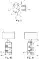
- FIG. 1 shows one way how the extraction ports 6a, 6b, etc. of the device according to FIG figure 1 can be sealed in a way that minimizes the risk of mixing up used and fresh connectors.
- a number of film covers 13a, 13b, etc. corresponding to the number of extraction ports 6a, 6b, etc. are provided, which surround each other like Russian dolls.
- the innermost casing 13z surrounds only the innermost extraction connection 6z and each further casing surrounds the existing casing and a further extraction connection. If the outermost enclosure 13a, starting from the fully closed position of the Figure 4a , opened by a user, the first extraction port 6a as well as the next cover 13b, which seals all further extraction ports 6b etc., is released. If this next enclosure 13b is opened, another removal connection and the next but one enclosure are released, as in Figure 4b shown, and so on. Only after opening the innermost cover 13z is the last removal connection 6z released.
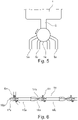
- figure 5 shows a variant of the invention in which the main extraction line 2 opens into a distributor 14 and the individual extraction lines 5a, 5b, etc. branch out from the distributor 14 in a star shape.
- the distributor 14 has a rotary switch which is designed in such a way that it can only be turned counterclockwise, as indicated by an arrow in the figure.
- a line is arranged in the drum of the rotary switch, so that only one individual removal line 5a, 5b, etc. can be released at a time.
- the individual extraction lines are provided with extraction connections and clamps fitted like this related to figure 1 was explained in more detail.
- figure 6 12 shows a variant of the invention with a line system consisting of a sampling line 15 with a plurality of sampling sectors 16a, 16b, etc. arranged in series, which are connected to one another by means of connectors 17a, 17b, etc.
- the extraction line 15 is at her in the figure 6 right end connected to the solution bag, like this related to figure 1 was declared for the main withdrawal line.
- the connectors 17a, 17b, etc. each include extraction ports 6a, 6b, etc., which as in connection with FIG figure 2 are declared trained.
- the connectors 17a, 17b, etc. each include a predetermined separation point 18a, 18b, etc., in order to be able to uncouple the extraction sectors 16a, 16b, etc.
- the connector 17b can be cut off at the predetermined separation point 18b after the extraction port 6a has been in use for a treatment and this use has ended.
- the connection at the predetermined separation points 18a, 18b, etc. can in principle be cut in any manner, for example by breaking, with the predetermined separation points 18a, 18b, etc. preferably being designed in such a way that the line leading to the decoupled sector is closed during decoupling, to prevent fresh Diasys solution from flowing out.
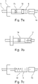
- the sleeve 19 is designed in such a way that, in the axial direction of the connection 6, it extends from an in Figure 7a shown open position in an in Figure 7c shown closed position can be pushed, wherein in the closed position of the extraction port 6 is blocked.
- the closed position is irreversible, since the sleeve 19 has a latching lug, not shown in detail in the figure, which in the closed position comes to rest behind or in the figure to the right of a latching projection, also not shown in detail in the figure.
- the sleeve 19 is biased by a spring 20 towards the closed position.
Landscapes
- Health & Medical Sciences (AREA)
- Heart & Thoracic Surgery (AREA)
- Urology & Nephrology (AREA)
- Emergency Medicine (AREA)
- Public Health (AREA)
- Engineering & Computer Science (AREA)
- Anesthesiology (AREA)
- Biomedical Technology (AREA)
- Hematology (AREA)
- Life Sciences & Earth Sciences (AREA)
- Animal Behavior & Ethology (AREA)
- General Health & Medical Sciences (AREA)
- Veterinary Medicine (AREA)
- Vascular Medicine (AREA)
- Pulmonology (AREA)
- External Artificial Organs (AREA)
Claims (10)
- Dispositif contenant un dialysat ou un concentré pour dialysat, de préférence destiné à être utilisé dans la dialyse péritonéale, comprenant un contenant de réception, qui peut renfermer un volume de solution qui est prévu pour au moins deux traitements,
caractérisé en ce que
le dispositif comporte plusieurs raccords de prélèvement pour le prélèvement du dialysat dans le contenant de réception et les raccords de prélèvement comportent une sécurité contre une double utilisation, qui ferme le raccord de prélèvement de manière irréversible après l'utilisation. - Dispositif selon la revendication 1, caractérisé en ce qu'une valve et un raccord de purge sont associés à chaque raccord de prélèvement.
- Dispositif selon l'une des revendications précédentes, caractérisé en ce que le dispositif comporte une conduite principale de prélèvement qui est reliée au contenant de réception et de laquelle partent plusieurs conduites individuelles de prélèvement avec les raccords de prélèvement.
- Dispositif selon la revendication 3, caractérisé en ce que des moyens de fermeture sont disposés dans chaque conduite individuelle de prélèvement, avec lesquels les conduites individuelles de prélèvement peuvent être fermées.
- Dispositif selon la revendication 4, caractérisé en ce que les moyens de fermeture sont conçus de manière à se fermer automatiquement lors de ou après un désaccouplement de la conduite individuelle de prélèvement du patient.
- Dispositif selon l'une des revendications 3 à 5, caractérisé en ce que les conduites individuelles de prélèvement bifurquent en différents points de branchement de la conduite principale de prélèvement, lesdits points de branchement étant répartis sur la longueur de la conduite principale de prélèvement.
- Dispositif selon la revendication 6, caractérisé en ce que des moyens de fermeture sont disposés respectivement dans la conduite principale de prélèvement entre des points de branchement se suivant de la conduite individuelle de prélèvement, lesdits moyens de fermeture permettant de fermer la conduite principale de prélèvement.
- Dispositif selon l'une des revendications 3 à 5, caractérisé en ce que la conduite principale de prélèvement débouche dans un élément de répartition et les conduites individuelles de prélèvement partent en étoile de l'élément de répartition.
- Dispositif selon la revendication 1 ou 2, caractérisé en ce que le dispositif comporte une conduite de prélèvement, sur laquelle les raccords de prélèvement sont disposés en série, dans lequel il est de préférence prévu que la conduite de prélèvement soit divisée en plusieurs secteurs pouvant être désaccouplés et qu'un raccord de prélèvement soit disposé dans chacun des secteurs.
- Dispositif selon l'une des revendications précédentes, caractérisé en ce que les raccords de prélèvement sont scellés individuellement avec des enveloppes étanches à l'air, dans lequel il est de préférence prévu qu'il y ait un nombre d'enveloppes correspondant au nombre de raccords de prélèvement, une enveloppe la plus à l'intérieur renfermant un raccord de prélèvement et chaque enveloppe supplémentaire renfermant l'enveloppe existante et un autre raccord de prélèvement.
Applications Claiming Priority (2)
| Application Number | Priority Date | Filing Date | Title |
|---|---|---|---|
| DE102018103937.9A DE102018103937A1 (de) | 2018-02-21 | 2018-02-21 | Vorrichtung enthaltend Dialyselösung oder Dialyselösungskonzentrat |
| PCT/EP2019/053641 WO2019162178A1 (fr) | 2018-02-21 | 2019-02-14 | Dispositif contenant une solution de dialyse ou un concentré de solution de dialyse |
Publications (2)
| Publication Number | Publication Date |
|---|---|
| EP3755397A1 EP3755397A1 (fr) | 2020-12-30 |
| EP3755397B1 true EP3755397B1 (fr) | 2022-11-02 |
Family
ID=65516508
Family Applications (1)
| Application Number | Title | Priority Date | Filing Date |
|---|---|---|---|
| EP19706456.1A Active EP3755397B1 (fr) | 2018-02-21 | 2019-02-14 | Dispositif contenant du dialysat ou du concentré pour le dialysat |
Country Status (8)
| Country | Link |
|---|---|
| US (1) | US12178947B2 (fr) |
| EP (1) | EP3755397B1 (fr) |
| JP (1) | JP7350758B2 (fr) |
| CN (1) | CN111886036B (fr) |
| BR (1) | BR112020017174A2 (fr) |
| DE (1) | DE102018103937A1 (fr) |
| ES (1) | ES2937358T3 (fr) |
| WO (1) | WO2019162178A1 (fr) |
Families Citing this family (1)
| Publication number | Priority date | Publication date | Assignee | Title |
|---|---|---|---|---|
| TW202208005A (zh) * | 2020-07-01 | 2022-03-01 | 新加坡商阿瓦克科技私人有限公司 | 腹膜透析分析裝置 |
Family Cites Families (35)
| Publication number | Priority date | Publication date | Assignee | Title |
|---|---|---|---|---|
| US4298001A (en) * | 1980-08-08 | 1981-11-03 | Hargest Iii Thomas S | Fluid flow connector unit and method |
| SE455470B (sv) * | 1981-06-23 | 1988-07-18 | Terumo Corp | Koppling for ihopkoppling av tva slangar for medicinskt, terapeutiskt bruk |
| US4950230A (en) * | 1987-03-19 | 1990-08-21 | Delmed, Inc. | Method and apparatus for bagless continuous ambulatory peritoneal dialysis |
| US5053003A (en) * | 1989-04-18 | 1991-10-01 | Dadson Joseph E | Method and apparatus for peritoneal dialysis using a "Y" tubing set |
| US5497763A (en) * | 1993-05-21 | 1996-03-12 | Aradigm Corporation | Disposable package for intrapulmonary delivery of aerosolized formulations |
| SE502020C2 (sv) * | 1994-02-03 | 1995-07-17 | Gambro Ab | Apparat för peritonealdialys |
| DE19520916A1 (de) * | 1995-06-08 | 1997-01-09 | Schael Wilfried | Einrichtung zur Versorgung von Hämodialysegeräten mit Dialysierflüssigkeit |
| JP3898313B2 (ja) * | 1997-11-27 | 2007-03-28 | 積水化学工業株式会社 | 医療用管継手 |
| SE512349C2 (sv) * | 1997-11-28 | 2000-03-06 | Gambro Lundia Ab | Flerkammarbehållare för medicinsk lösning, förfarnde för beredning av medicinsk lösning för peritonealdialys samt användning av sådan behållare vid beredning av medicinsk lösning |
| JP4543335B2 (ja) | 1998-07-13 | 2010-09-15 | 株式会社ジェイ・エム・エス | 医療用チューブコネクタ装置 |
| TW477696B (en) * | 1998-07-29 | 2002-03-01 | Mesibo As | A bag system for collecting and storing blood and a method therefor |
| US7559913B1 (en) * | 2000-02-28 | 2009-07-14 | Gambro Lundia Ab | Method and device for PD cyclers |
| US7384416B2 (en) * | 2002-08-12 | 2008-06-10 | Macopharma | Device and method for irreversible closure of fluid communication in a container system |
| JP2006052863A (ja) * | 2004-08-09 | 2006-02-23 | Toshiba Kyaria Kk | 冷凍サイクル装置の配管接続継手 |
| FR2909649B1 (fr) * | 2006-12-11 | 2009-07-03 | Maurice Granger | Embout jetable pour bobine de materiau d'essuyage et appareil distributeur de materiau d'essuyage recevant un tel embout |
| DE102007017816A1 (de) * | 2007-04-16 | 2008-10-30 | Hecht Anlagenbau Gmbh | Adaptervorrichtung für Behälter zur kontaminationsfreien Entnahme deren Inhalts |
| CN201052268Y (zh) * | 2007-07-11 | 2008-04-30 | 张厚勤 | 输血袋 |
| GB0805297D0 (en) * | 2008-03-20 | 2008-04-30 | Scottish & Newcastle Plc | Beverage dispense apparatus |
| US20100217179A1 (en) | 2009-02-20 | 2010-08-26 | Baxter International Inc. | Bulk delivery peritoneal dialysis system and method |
| CN201414968Y (zh) * | 2009-05-31 | 2010-03-03 | 广东龙心医疗器械有限公司 | 一次性使用安全静脉留置针 |
| EP2258418A1 (fr) * | 2009-06-05 | 2010-12-08 | Fresenius Medical Care Deutschland GmbH | Dispositif de collecte d'échantillons |
| US20120284991A1 (en) * | 2009-12-07 | 2012-11-15 | Matthew Kusz | Configurable port fitment, kit, and related methods |
| EP2332610B1 (fr) * | 2009-12-10 | 2013-02-13 | Fresenius Kabi Deutschland GmbH | Système de raccordement pour récipients d'aliments destinés à la nutrition entérale |
| DE102009060330A1 (de) * | 2009-12-23 | 2011-06-30 | Fresenius Medical Care Deutschland GmbH, 61352 | Dialysemaschine, insbesondere Peritonealdialysemaschine |
| US20110251489A1 (en) * | 2010-04-07 | 2011-10-13 | Physiosonics, Inc. | Ultrasound monitoring systems, methods and components |
| DE102011008223B4 (de) * | 2011-01-10 | 2019-07-04 | Fresenius Medical Care Deutschland Gmbh | Dialysebehandlungseinheit |
| JP5818538B2 (ja) * | 2011-06-30 | 2015-11-18 | 株式会社トップ | 留置針 |
| CN202699174U (zh) * | 2012-08-01 | 2013-01-30 | 郑州信翰科技开发有限公司 | 医用探头隔离护套及采用该护套的安全隔离护套装置 |
| CN105142692B (zh) * | 2013-03-14 | 2018-10-09 | 贝克斯特国际公司 | 具有可再用供能单元的用于腹膜透析交换的系统和方法 |
| CN105916542B (zh) | 2014-02-18 | 2020-01-14 | 拜耳医药保健有限公司 | 多剂量一次性系统 |
| CN204319274U (zh) * | 2014-12-16 | 2015-05-13 | 深圳市茵冠生物科技有限公司 | 用于回输细胞的输液袋 |
| EP3034062B1 (fr) * | 2014-12-19 | 2017-03-22 | Fresenius Kabi Deutschland GmbH | Système de connecteur ayant au moins deux ports de prélèvement |
| CN204745116U (zh) * | 2015-07-22 | 2015-11-11 | 金华市中心医院 | 用于连接中心静脉导管与普通引流袋的转换接头 |
| CN107662757A (zh) * | 2016-07-29 | 2018-02-06 | 重庆莱美药业股份有限公司 | 一种组合盖、带组合盖的接口及包装容器 |
| DE102017000495A1 (de) * | 2017-01-20 | 2018-07-26 | Fresenius Medical Care Deutschland Gmbh | DlALYSATKONZENTRATlON-MESSSENSORDlAGNOSE |
-
2018
- 2018-02-21 DE DE102018103937.9A patent/DE102018103937A1/de not_active Ceased
-
2019
- 2019-02-14 EP EP19706456.1A patent/EP3755397B1/fr active Active
- 2019-02-14 ES ES19706456T patent/ES2937358T3/es active Active
- 2019-02-14 JP JP2020544475A patent/JP7350758B2/ja active Active
- 2019-02-14 BR BR112020017174-3A patent/BR112020017174A2/pt active Search and Examination
- 2019-02-14 WO PCT/EP2019/053641 patent/WO2019162178A1/fr not_active Ceased
- 2019-02-14 US US16/971,456 patent/US12178947B2/en active Active
- 2019-02-14 CN CN201980020759.7A patent/CN111886036B/zh active Active
Also Published As
| Publication number | Publication date |
|---|---|
| ES2937358T3 (es) | 2023-03-28 |
| JP2021514268A (ja) | 2021-06-10 |
| US12178947B2 (en) | 2024-12-31 |
| JP7350758B2 (ja) | 2023-09-26 |
| DE102018103937A1 (de) | 2019-08-22 |
| CN111886036B (zh) | 2023-08-11 |
| US20200397970A1 (en) | 2020-12-24 |
| CN111886036A (zh) | 2020-11-03 |
| BR112020017174A2 (pt) | 2020-12-22 |
| EP3755397A1 (fr) | 2020-12-30 |
| WO2019162178A1 (fr) | 2019-08-29 |
Similar Documents
| Publication | Publication Date | Title |
|---|---|---|
| DE3513205C1 (de) | Konnektor fuer die Peritonealdialyse | |
| DE2947574C2 (de) | Schlauchkupplung für keimfrei zu haltende Leitungsverbinder | |
| DE3143329C2 (de) | Schutzvorrichtung für einen Verbindungsstöpsel von medizinischen Schlauchsystemen | |
| EP2825248B1 (fr) | Dispositif médical doté d'une unité connecteur femelle pour le raccordement d'un dispositif de fourniture de liquides médicinaux | |
| EP0197553B1 (fr) | Système pour dialyse péritonéale et connecteur pour un tel système | |
| EP2836247B1 (fr) | Dispositif de recirculation d'un appareil de traitement sanguin extracorporel | |
| DE3852638T2 (de) | Beutellose, kontinuierliche, ambulante peritonealdialyse. | |
| DE2815058A1 (de) | Katheteranordnung | |
| DE3627231C2 (de) | Überleitungsgerät zum Mischen von in unterschiedlichen Behältern befindlichen Medikamenten | |
| EP2877219A1 (fr) | Système mobile de séparation par gravité du sang de donneurs | |
| CH670955A5 (en) | Two=part coupling for medical liq. exchange - has sleeves with chambers, each contg. tube, and elastic component in second chamber | |
| DE2256748A1 (de) | Kanuele zum einfuehren eines flexiblen katheters | |
| EP1894555A2 (fr) | Dispositif pour l'extraction de liquides | |
| EP3755397A1 (fr) | Dispositif contenant une solution de dialyse ou un concentré de solution de dialyse | |
| EP2114486B1 (fr) | Appareil médical | |
| DE202011004487U1 (de) | Vorrichtung zur Abfüllung von Blutprodukten | |
| DE3613689C2 (fr) | ||
| EP4308206A1 (fr) | Raccord d'un tube de perfusion, ensemble de perfusion et procédé de purge d'un tube de perfusion | |
| EP1721595B1 (fr) | Récipient pour délivrer des liquides médicaux | |
| DE3828903C2 (fr) | ||
| DE102015117649A1 (de) | Verbindungssatz und Verfahren zum sterilen Verbinden | |
| DE69917383T2 (de) | Beutel für Hämofiltrationsflüssigkeit | |
| DE102021121108A1 (de) | Mehrteiliger Dialysator | |
| EP0512281A1 (fr) | Raccord pour récipient d'une solution pharmaceutique | |
| WO2019162189A1 (fr) | Contenant destiné à recevoir une solution de dialyse |
Legal Events
| Date | Code | Title | Description |
|---|---|---|---|
| STAA | Information on the status of an ep patent application or granted ep patent |
Free format text: STATUS: UNKNOWN |
|
| STAA | Information on the status of an ep patent application or granted ep patent |
Free format text: STATUS: THE INTERNATIONAL PUBLICATION HAS BEEN MADE |
|
| PUAI | Public reference made under article 153(3) epc to a published international application that has entered the european phase |
Free format text: ORIGINAL CODE: 0009012 |
|
| STAA | Information on the status of an ep patent application or granted ep patent |
Free format text: STATUS: REQUEST FOR EXAMINATION WAS MADE |
|
| 17P | Request for examination filed |
Effective date: 20200911 |
|
| AK | Designated contracting states |
Kind code of ref document: A1 Designated state(s): AL AT BE BG CH CY CZ DE DK EE ES FI FR GB GR HR HU IE IS IT LI LT LU LV MC MK MT NL NO PL PT RO RS SE SI SK SM TR |
|
| AX | Request for extension of the european patent |
Extension state: BA ME |
|
| DAV | Request for validation of the european patent (deleted) | ||
| DAX | Request for extension of the european patent (deleted) | ||
| GRAP | Despatch of communication of intention to grant a patent |
Free format text: ORIGINAL CODE: EPIDOSNIGR1 |
|
| STAA | Information on the status of an ep patent application or granted ep patent |
Free format text: STATUS: GRANT OF PATENT IS INTENDED |
|
| INTG | Intention to grant announced |
Effective date: 20220530 |
|
| GRAS | Grant fee paid |
Free format text: ORIGINAL CODE: EPIDOSNIGR3 |
|
| GRAA | (expected) grant |
Free format text: ORIGINAL CODE: 0009210 |
|
| STAA | Information on the status of an ep patent application or granted ep patent |
Free format text: STATUS: THE PATENT HAS BEEN GRANTED |
|
| AK | Designated contracting states |
Kind code of ref document: B1 Designated state(s): AL AT BE BG CH CY CZ DE DK EE ES FI FR GB GR HR HU IE IS IT LI LT LU LV MC MK MT NL NO PL PT RO RS SE SI SK SM TR |
|
| REG | Reference to a national code |
Ref country code: GB Ref legal event code: FG4D Free format text: NOT ENGLISH |
|
| REG | Reference to a national code |
Ref country code: CH Ref legal event code: EP Ref country code: AT Ref legal event code: REF Ref document number: 1528288 Country of ref document: AT Kind code of ref document: T Effective date: 20221115 |
|
| REG | Reference to a national code |
Ref country code: DE Ref legal event code: R096 Ref document number: 502019006126 Country of ref document: DE |
|
| REG | Reference to a national code |
Ref country code: IE Ref legal event code: FG4D Free format text: LANGUAGE OF EP DOCUMENT: GERMAN |
|
| REG | Reference to a national code |
Ref country code: LT Ref legal event code: MG9D |
|
| REG | Reference to a national code |
Ref country code: NL Ref legal event code: MP Effective date: 20221102 |
|
| REG | Reference to a national code |
Ref country code: ES Ref legal event code: FG2A Ref document number: 2937358 Country of ref document: ES Kind code of ref document: T3 Effective date: 20230328 |
|
| PG25 | Lapsed in a contracting state [announced via postgrant information from national office to epo] |
Ref country code: SE Free format text: LAPSE BECAUSE OF FAILURE TO SUBMIT A TRANSLATION OF THE DESCRIPTION OR TO PAY THE FEE WITHIN THE PRESCRIBED TIME-LIMIT Effective date: 20221102 Ref country code: PT Free format text: LAPSE BECAUSE OF FAILURE TO SUBMIT A TRANSLATION OF THE DESCRIPTION OR TO PAY THE FEE WITHIN THE PRESCRIBED TIME-LIMIT Effective date: 20230302 Ref country code: NO Free format text: LAPSE BECAUSE OF FAILURE TO SUBMIT A TRANSLATION OF THE DESCRIPTION OR TO PAY THE FEE WITHIN THE PRESCRIBED TIME-LIMIT Effective date: 20230202 Ref country code: LT Free format text: LAPSE BECAUSE OF FAILURE TO SUBMIT A TRANSLATION OF THE DESCRIPTION OR TO PAY THE FEE WITHIN THE PRESCRIBED TIME-LIMIT Effective date: 20221102 Ref country code: FI Free format text: LAPSE BECAUSE OF FAILURE TO SUBMIT A TRANSLATION OF THE DESCRIPTION OR TO PAY THE FEE WITHIN THE PRESCRIBED TIME-LIMIT Effective date: 20221102 |
|
| PG25 | Lapsed in a contracting state [announced via postgrant information from national office to epo] |
Ref country code: RS Free format text: LAPSE BECAUSE OF FAILURE TO SUBMIT A TRANSLATION OF THE DESCRIPTION OR TO PAY THE FEE WITHIN THE PRESCRIBED TIME-LIMIT Effective date: 20221102 Ref country code: PL Free format text: LAPSE BECAUSE OF FAILURE TO SUBMIT A TRANSLATION OF THE DESCRIPTION OR TO PAY THE FEE WITHIN THE PRESCRIBED TIME-LIMIT Effective date: 20221102 Ref country code: LV Free format text: LAPSE BECAUSE OF FAILURE TO SUBMIT A TRANSLATION OF THE DESCRIPTION OR TO PAY THE FEE WITHIN THE PRESCRIBED TIME-LIMIT Effective date: 20221102 Ref country code: IS Free format text: LAPSE BECAUSE OF FAILURE TO SUBMIT A TRANSLATION OF THE DESCRIPTION OR TO PAY THE FEE WITHIN THE PRESCRIBED TIME-LIMIT Effective date: 20230302 Ref country code: HR Free format text: LAPSE BECAUSE OF FAILURE TO SUBMIT A TRANSLATION OF THE DESCRIPTION OR TO PAY THE FEE WITHIN THE PRESCRIBED TIME-LIMIT Effective date: 20221102 Ref country code: GR Free format text: LAPSE BECAUSE OF FAILURE TO SUBMIT A TRANSLATION OF THE DESCRIPTION OR TO PAY THE FEE WITHIN THE PRESCRIBED TIME-LIMIT Effective date: 20230203 |
|
| PG25 | Lapsed in a contracting state [announced via postgrant information from national office to epo] |
Ref country code: NL Free format text: LAPSE BECAUSE OF FAILURE TO SUBMIT A TRANSLATION OF THE DESCRIPTION OR TO PAY THE FEE WITHIN THE PRESCRIBED TIME-LIMIT Effective date: 20221102 |
|
| P01 | Opt-out of the competence of the unified patent court (upc) registered |
Effective date: 20230602 |
|
| PG25 | Lapsed in a contracting state [announced via postgrant information from national office to epo] |
Ref country code: SM Free format text: LAPSE BECAUSE OF FAILURE TO SUBMIT A TRANSLATION OF THE DESCRIPTION OR TO PAY THE FEE WITHIN THE PRESCRIBED TIME-LIMIT Effective date: 20221102 Ref country code: RO Free format text: LAPSE BECAUSE OF FAILURE TO SUBMIT A TRANSLATION OF THE DESCRIPTION OR TO PAY THE FEE WITHIN THE PRESCRIBED TIME-LIMIT Effective date: 20221102 Ref country code: EE Free format text: LAPSE BECAUSE OF FAILURE TO SUBMIT A TRANSLATION OF THE DESCRIPTION OR TO PAY THE FEE WITHIN THE PRESCRIBED TIME-LIMIT Effective date: 20221102 Ref country code: DK Free format text: LAPSE BECAUSE OF FAILURE TO SUBMIT A TRANSLATION OF THE DESCRIPTION OR TO PAY THE FEE WITHIN THE PRESCRIBED TIME-LIMIT Effective date: 20221102 Ref country code: CZ Free format text: LAPSE BECAUSE OF FAILURE TO SUBMIT A TRANSLATION OF THE DESCRIPTION OR TO PAY THE FEE WITHIN THE PRESCRIBED TIME-LIMIT Effective date: 20221102 |
|
| REG | Reference to a national code |
Ref country code: DE Ref legal event code: R097 Ref document number: 502019006126 Country of ref document: DE |
|
| PG25 | Lapsed in a contracting state [announced via postgrant information from national office to epo] |
Ref country code: SK Free format text: LAPSE BECAUSE OF FAILURE TO SUBMIT A TRANSLATION OF THE DESCRIPTION OR TO PAY THE FEE WITHIN THE PRESCRIBED TIME-LIMIT Effective date: 20221102 Ref country code: AL Free format text: LAPSE BECAUSE OF FAILURE TO SUBMIT A TRANSLATION OF THE DESCRIPTION OR TO PAY THE FEE WITHIN THE PRESCRIBED TIME-LIMIT Effective date: 20221102 |
|
| PLBE | No opposition filed within time limit |
Free format text: ORIGINAL CODE: 0009261 |
|
| STAA | Information on the status of an ep patent application or granted ep patent |
Free format text: STATUS: NO OPPOSITION FILED WITHIN TIME LIMIT |
|
| PG25 | Lapsed in a contracting state [announced via postgrant information from national office to epo] |
Ref country code: MC Free format text: LAPSE BECAUSE OF FAILURE TO SUBMIT A TRANSLATION OF THE DESCRIPTION OR TO PAY THE FEE WITHIN THE PRESCRIBED TIME-LIMIT Effective date: 20221102 |
|
| REG | Reference to a national code |
Ref country code: CH Ref legal event code: PL |
|
| 26N | No opposition filed |
Effective date: 20230803 |
|
| REG | Reference to a national code |
Ref country code: BE Ref legal event code: MM Effective date: 20230228 |
|
| PG25 | Lapsed in a contracting state [announced via postgrant information from national office to epo] |
Ref country code: LU Free format text: LAPSE BECAUSE OF NON-PAYMENT OF DUE FEES Effective date: 20230214 Ref country code: LI Free format text: LAPSE BECAUSE OF NON-PAYMENT OF DUE FEES Effective date: 20230228 Ref country code: CH Free format text: LAPSE BECAUSE OF NON-PAYMENT OF DUE FEES Effective date: 20230228 |
|
| PG25 | Lapsed in a contracting state [announced via postgrant information from national office to epo] |
Ref country code: SI Free format text: LAPSE BECAUSE OF FAILURE TO SUBMIT A TRANSLATION OF THE DESCRIPTION OR TO PAY THE FEE WITHIN THE PRESCRIBED TIME-LIMIT Effective date: 20221102 |
|
| PG25 | Lapsed in a contracting state [announced via postgrant information from national office to epo] |
Ref country code: BE Free format text: LAPSE BECAUSE OF NON-PAYMENT OF DUE FEES Effective date: 20230228 |
|
| PG25 | Lapsed in a contracting state [announced via postgrant information from national office to epo] |
Ref country code: BG Free format text: LAPSE BECAUSE OF FAILURE TO SUBMIT A TRANSLATION OF THE DESCRIPTION OR TO PAY THE FEE WITHIN THE PRESCRIBED TIME-LIMIT Effective date: 20221102 |
|
| PG25 | Lapsed in a contracting state [announced via postgrant information from national office to epo] |
Ref country code: BG Free format text: LAPSE BECAUSE OF FAILURE TO SUBMIT A TRANSLATION OF THE DESCRIPTION OR TO PAY THE FEE WITHIN THE PRESCRIBED TIME-LIMIT Effective date: 20221102 |
|
| REG | Reference to a national code |
Ref country code: AT Ref legal event code: MM01 Ref document number: 1528288 Country of ref document: AT Kind code of ref document: T Effective date: 20240214 |
|
| PG25 | Lapsed in a contracting state [announced via postgrant information from national office to epo] |
Ref country code: AT Free format text: LAPSE BECAUSE OF NON-PAYMENT OF DUE FEES Effective date: 20240214 |
|
| PG25 | Lapsed in a contracting state [announced via postgrant information from national office to epo] |
Ref country code: CY Free format text: LAPSE BECAUSE OF FAILURE TO SUBMIT A TRANSLATION OF THE DESCRIPTION OR TO PAY THE FEE WITHIN THE PRESCRIBED TIME-LIMIT; INVALID AB INITIO Effective date: 20190214 |
|
| PG25 | Lapsed in a contracting state [announced via postgrant information from national office to epo] |
Ref country code: HU Free format text: LAPSE BECAUSE OF FAILURE TO SUBMIT A TRANSLATION OF THE DESCRIPTION OR TO PAY THE FEE WITHIN THE PRESCRIBED TIME-LIMIT; INVALID AB INITIO Effective date: 20190214 |
|
| PG25 | Lapsed in a contracting state [announced via postgrant information from national office to epo] |
Ref country code: TR Free format text: LAPSE BECAUSE OF FAILURE TO SUBMIT A TRANSLATION OF THE DESCRIPTION OR TO PAY THE FEE WITHIN THE PRESCRIBED TIME-LIMIT Effective date: 20221102 |
|
| PGFP | Annual fee paid to national office [announced via postgrant information from national office to epo] |
Ref country code: GB Payment date: 20260122 Year of fee payment: 8 |
|
| PGFP | Annual fee paid to national office [announced via postgrant information from national office to epo] |
Ref country code: ES Payment date: 20260302 Year of fee payment: 8 |
|
| PGFP | Annual fee paid to national office [announced via postgrant information from national office to epo] |
Ref country code: DE Payment date: 20260121 Year of fee payment: 8 Ref country code: IE Payment date: 20260123 Year of fee payment: 8 |
|
| PGFP | Annual fee paid to national office [announced via postgrant information from national office to epo] |
Ref country code: AT Payment date: 20260410 Year of fee payment: 5 |
|
| PGFP | Annual fee paid to national office [announced via postgrant information from national office to epo] |
Ref country code: IT Payment date: 20260121 Year of fee payment: 8 |
|
| PGFP | Annual fee paid to national office [announced via postgrant information from national office to epo] |
Ref country code: FR Payment date: 20260121 Year of fee payment: 8 |