EP3755397B1 - Device containing dialysate or dialysate concentrate - Google Patents
Device containing dialysate or dialysate concentrate Download PDFInfo
- Publication number
- EP3755397B1 EP3755397B1 EP19706456.1A EP19706456A EP3755397B1 EP 3755397 B1 EP3755397 B1 EP 3755397B1 EP 19706456 A EP19706456 A EP 19706456A EP 3755397 B1 EP3755397 B1 EP 3755397B1
- Authority
- EP
- European Patent Office
- Prior art keywords
- extraction
- line
- accordance
- main
- connection
- Prior art date
- Legal status (The legal status is an assumption and is not a legal conclusion. Google has not performed a legal analysis and makes no representation as to the accuracy of the status listed.)
- Active
Links
- 239000012141 concentrate Substances 0.000 title claims description 8
- 238000000605 extraction Methods 0.000 claims description 105
- 239000000385 dialysis solution Substances 0.000 claims description 30
- 239000000243 solution Substances 0.000 claims description 12
- 238000011282 treatment Methods 0.000 claims description 11
- 238000000502 dialysis Methods 0.000 claims description 6
- 238000005070 sampling Methods 0.000 description 8
- 239000007788 liquid Substances 0.000 description 7
- 238000000034 method Methods 0.000 description 6
- 230000008569 process Effects 0.000 description 6
- 238000000926 separation method Methods 0.000 description 6
- 238000010079 rubber tapping Methods 0.000 description 4
- 210000000683 abdominal cavity Anatomy 0.000 description 3
- 230000008901 benefit Effects 0.000 description 3
- 239000011888 foil Substances 0.000 description 3
- 210000001015 abdomen Anatomy 0.000 description 2
- 230000036512 infertility Effects 0.000 description 2
- 230000002427 irreversible effect Effects 0.000 description 2
- 238000002156 mixing Methods 0.000 description 2
- 238000004806 packaging method and process Methods 0.000 description 2
- 238000007789 sealing Methods 0.000 description 2
- 239000002699 waste material Substances 0.000 description 2
- 230000004888 barrier function Effects 0.000 description 1
- 238000011109 contamination Methods 0.000 description 1
- 239000012530 fluid Substances 0.000 description 1
- 238000004519 manufacturing process Methods 0.000 description 1
- 230000007246 mechanism Effects 0.000 description 1
- 210000004303 peritoneum Anatomy 0.000 description 1
- 238000003908 quality control method Methods 0.000 description 1
- 230000009467 reduction Effects 0.000 description 1
- 238000001223 reverse osmosis Methods 0.000 description 1
- 239000008223 sterile water Substances 0.000 description 1
- 238000011144 upstream manufacturing Methods 0.000 description 1
- XLYOFNOQVPJJNP-UHFFFAOYSA-N water Chemical compound O XLYOFNOQVPJJNP-UHFFFAOYSA-N 0.000 description 1
Images


Classifications
-
- A—HUMAN NECESSITIES
- A61—MEDICAL OR VETERINARY SCIENCE; HYGIENE
- A61M—DEVICES FOR INTRODUCING MEDIA INTO, OR ONTO, THE BODY; DEVICES FOR TRANSDUCING BODY MEDIA OR FOR TAKING MEDIA FROM THE BODY; DEVICES FOR PRODUCING OR ENDING SLEEP OR STUPOR
- A61M1/00—Suction or pumping devices for medical purposes; Devices for carrying-off, for treatment of, or for carrying-over, body-liquids; Drainage systems
- A61M1/14—Dialysis systems; Artificial kidneys; Blood oxygenators ; Reciprocating systems for treatment of body fluids, e.g. single needle systems for hemofiltration or pheresis
- A61M1/28—Peritoneal dialysis ; Other peritoneal treatment, e.g. oxygenation
-
- A—HUMAN NECESSITIES
- A61—MEDICAL OR VETERINARY SCIENCE; HYGIENE
- A61M—DEVICES FOR INTRODUCING MEDIA INTO, OR ONTO, THE BODY; DEVICES FOR TRANSDUCING BODY MEDIA OR FOR TAKING MEDIA FROM THE BODY; DEVICES FOR PRODUCING OR ENDING SLEEP OR STUPOR
- A61M1/00—Suction or pumping devices for medical purposes; Devices for carrying-off, for treatment of, or for carrying-over, body-liquids; Drainage systems
- A61M1/14—Dialysis systems; Artificial kidneys; Blood oxygenators ; Reciprocating systems for treatment of body fluids, e.g. single needle systems for hemofiltration or pheresis
- A61M1/16—Dialysis systems; Artificial kidneys; Blood oxygenators ; Reciprocating systems for treatment of body fluids, e.g. single needle systems for hemofiltration or pheresis with membranes
- A61M1/1654—Dialysates therefor
- A61M1/1656—Apparatus for preparing dialysates
- A61M1/1668—Details of containers
-
- A—HUMAN NECESSITIES
- A61—MEDICAL OR VETERINARY SCIENCE; HYGIENE
- A61M—DEVICES FOR INTRODUCING MEDIA INTO, OR ONTO, THE BODY; DEVICES FOR TRANSDUCING BODY MEDIA OR FOR TAKING MEDIA FROM THE BODY; DEVICES FOR PRODUCING OR ENDING SLEEP OR STUPOR
- A61M1/00—Suction or pumping devices for medical purposes; Devices for carrying-off, for treatment of, or for carrying-over, body-liquids; Drainage systems
- A61M1/14—Dialysis systems; Artificial kidneys; Blood oxygenators ; Reciprocating systems for treatment of body fluids, e.g. single needle systems for hemofiltration or pheresis
- A61M1/28—Peritoneal dialysis ; Other peritoneal treatment, e.g. oxygenation
- A61M1/285—Catheters therefor
-
- A—HUMAN NECESSITIES
- A61—MEDICAL OR VETERINARY SCIENCE; HYGIENE
- A61M—DEVICES FOR INTRODUCING MEDIA INTO, OR ONTO, THE BODY; DEVICES FOR TRANSDUCING BODY MEDIA OR FOR TAKING MEDIA FROM THE BODY; DEVICES FOR PRODUCING OR ENDING SLEEP OR STUPOR
- A61M39/00—Tubes, tube connectors, tube couplings, valves, access sites or the like, specially adapted for medical use
- A61M39/22—Valves or arrangement of valves
- A61M39/223—Multiway valves
Definitions
- the invention relates to a device containing a dialysis solution or a dialysis solution concentrate, preferably for use in peritoneal dialysis, with a receptacle that can hold a volume of solution intended for at least two treatments.
- US2014/276373A1 discloses a peritoneal dialysis machine that has a receptacle that can hold a volume of dialysis solution intended for at least two treatments, the device having a plurality of extraction ports for removing the dialysis solution from the receptacle.
- the object of the invention is to find a suitable connection concept for repeated removal of dialysis solution from the same receptacle, in which the sterility of the removal connection is reliably guaranteed, especially after the first removal and further removals.
- the invention relates to a device containing a dialysis solution or a dialysis solution concentrate, preferably for use in peritoneal dialysis, with a receptacle that can hold a volume of solution intended for at least two treatments, the device having a plurality of extraction connections for removing the dialysis solution has the receiving container and the extraction connections have a double insurance that irreversibly closes the extraction connection after use.
- a treatment is understood to mean a complete or partial filling of the patient's abdomen.
- a withdrawal connection is understood as an interface for the direct or indirect connection of the line leading into the abdominal cavity of the patient, ie the patient catheter.
- the removal connection can be provided with a Luer connector, for example.
- a fresh removal connection can be used for each of several removals of dialysis solution from the receptacle.
- the receptacle can have a volume of more than 5 liters, more than 10 liters or even more than 20 liters.
- the volume typically required in a single treatment is of the order of about 2 liters.
- the number of connections can be matched to the size of the receptacle.
- the device can have at least one removal connection per two liter volume of the receptacle.
- the receptacle In addition to the connections for removing the dialysis solution, the receptacle typically has a filling connection for filling with dialysis solution.
- the receptacle can be a flexible bag or a rigid container.
- a pressure equalizing valve can be provided.
- It can also be a flexible and preferably elastic bag stored in a rigid container.
- a bag-in-box packaging has the advantage that the inner bag, which is typically designed as a disposable, is protected from mechanical influences by the outer packaging.
- the mechanical robustness of the solution bag, in this case the inner bag is less important than previously known solutions, which allows for a material-saving and more cost-effective design. In particular due to the fact that solution bags are typically disposable products, the cost savings and waste savings are significant.
- the container can be transparent or have a transparent viewing window. If necessary, level markings can be provided.
- the device can optionally have a dosing container between the sampling ports and the receptacle to facilitate dosing the correct amount of liquid for a treatment.
- a valve and a drainage connection are assigned to each removal connection.
- each removal connection can also be used for a drainage process.
- suitable valves include rotary valves or 3/3-way valves.
- the device has a main extraction line which is connected to the receiving container and from which several individual extraction lines with extraction connections branch off.
- closing means are arranged in the individual extraction lines, with which the individual extraction lines can be closed.
- the closing means can be clamps, for example, with which the respective line can be disconnected.
- the closing means and preferably clamps are designed in such a way that the respective line can be closed irreversibly.
- the closing means are designed in such a way that they close automatically when or after the individual removal line is disconnected from the patient.
- the closing means are designed in such a way that it is impossible to reopen the single extraction line that has been used.
- the individual extraction lines branch off from the main extraction line at different branching points, which are distributed over the length of the main extraction line.
- the line system consisting of the main extraction line and the individual extraction lines has a tree structure in this embodiment, with the main extraction line corresponding to the trunk and the individual extraction lines to the branches. An individual line can be assigned to each extraction connection.
- closing means are arranged in the main extraction line between successive branching points of the individual extraction line, with which the main extraction line can be closed.
- the closing means can be designed as described in more detail above.
- the extraction line in question can be closed using a closing means, eg a clamp, a valve or a cock.
- the main bleed line can be closed off at a point between the branches of the last and penultimate bleed individual lines using a closing means.
- the penultimate withdrawal connection can then be used for the second withdrawal of liquid and this can then also be uncoupled by closing the individual withdrawal line or the main withdrawal line.
- This process can be repeated until the last extraction connection on the last single extraction line, ie the one closest to the receptacle, has been used or the entire dialysis solution in the receptacle has been used up.
- a decoupling at the main sampling line can have the advantage that less dead volume arises.
- the main extraction line opens into a distributor and the individual extraction lines leave the distributor in a star shape.
- the distributor can have a switch which is designed in such a way that it is only ever possible to release a single individual extraction line and that only such an individual extraction line can be released which has not been used before.
- An example of a suitable switch includes a rotary switch that can only be rotated in one direction.
- a connection mechanism can be provided at the upstream end of the main extraction line, which is designed to be able to uncouple the line system as a whole from the receiving container. For example, either the receptacle or the line system can be reused.
- the main extraction line and/or the individual extraction lines can have non-return valves as an additional contamination barrier.
- the device has a sampling line on which the sampling connections are arranged in series, it being preferably provided that the sampling line is divided into several detachable sectors and a sampling connection is arranged in each of the sectors.
- Closing means as described above can be arranged in the individual sectors in order to be able to decouple the sectors.
- the sectors may be interconnected by connectors having predetermined disconnect points to disconnect a sector with a used bleed port.
- the predetermined separation points are preferably designed in such a way that the passage is closed when the separation occurs.
- the extraction ports are individually sealed with airtight envelopes, it being preferably provided that that there is a number of casings corresponding to the number of tapping ports, with an innermost casing enclosing a tapping port and each additional casing enclosing the existing casing and a further tapping port.
- Suitable coverings include, for example, plastic bags, caps or the like. It can be provided that the covers follow the principle of a Russian doll. Opening the outermost wrapper reveals a bleed port and the next wrapper that seals all other bleed ports. Opening this next enclosure will expose another extraction port and the next but one enclosure, and so on. The last removal connection is only released after the innermost cover has been opened. This type of sealing minimizes the risk of confusing used and fresh connections.
- the last extraction connection can be on the last extraction line, i.e. the one closest to the receiving container, and the first extraction connection on the first extraction line, i.e. the furthest away from the receiving container, can only be on the outermost be surrounded by an envelope.
- the dual-use safeguard may include a moveable sleeve that is moveable from an open position to a closed position and, when closed, blocks the extraction port.
- the sleeve can be designed in such a way that it can be displaced from an open position to a closed position in the axial direction of the connection. Provision can be made for the closed position to be irreversible, ie the sleeve can no longer be pushed back from the closed to the open position. This arrest can be implemented, for example, by a latching projection and a latching lug. This effectively eliminates unwanted multiple use of the same port be avoided.
- the sleeve can be prestressed against the closed position, so that it is automatically transferred into the closed position after a holding element has been broken open.
- the holding element can be designed in such a way that it is broken open when the line leading into the abdominal cavity of the patient is coupled. The sleeve is then held by the patient line for as long as it is connected. When removed, the sleeve closes irreversibly.
- the container cannot contain a ready-to-use dialysis solution but only a concentrate.
- the ready-to-use dialysis solution can be prepared on site by filling the container with purified, sterile water, for example from a reverse osmosis system.
- the container also has a supply line for liquids, the supply line preferably being closable.
- the concentrate can be placed freely in the container or in a separate compartment. Several different concentrates can also be placed in several compartments.
- a breakable connection can be used to create a fluid connection between the concentrate compartments and a mixing compartment. In the event that the container is a film bag, peelable welded seams, for example, are suitable as breakable connections.
- FIG. 1 A first variant of a device according to the invention is figure 1 shown. It comprises a receptacle in the form of a foil bag 1, the dimensions of which are such that several portions of around two liters each of peritoneal dialysis solution can be accommodated.
- the foil bag 1 is realized with a main removal line 2 using a connection 3 with corresponding detachable connection partners, whereby the main removal line 2 can be removed from the foil bag 1 .
- An individual extraction line 5a, 5b, etc. branches off from the main extraction line 2 at different branching points 4a, 4b, etc., which are distributed in series over the length of the main extraction line.
- Each of the individual extraction lines has an extraction connection 6a, 6b, etc. at its end and is also provided with a clamp 7a, 7b, etc.
- a main clamp 8 is provided in the main extraction line 2 between the branching point 4z located closest to the bag and the pair of connecting elements 3 .
- the individual removal connections 6 can be designed as in figure 2 shown and include a Y-valve 9 to which the single removal line 4 is firmly connected and which has connectors for connecting a patient line 10 and a drainage line 11 .
- the withdrawal connection 6 can also be used for a drainage process, after the patient line 10 and the drainage line 11 have been connected, the valve 9 is first set so that used dialysis solution flows out of the patient line 10 into the drainage line 11 . The valve 9 can then be set in such a way that fresh dialysis solution can flow from the individual withdrawal line 4 into the patient line 10 .
- the individual extraction connections 6 can also be designed as in figure 3 shown and include a rotary switch 12 that can cycle through four positions. In position A, the rotary switch 12 is closed. In position B, used dialysis solution can flow out of the patient line 10 into the drainage line 11 . In position C, fresh dialysis solution can flow from the individual withdrawal line 4 into the patient line 10 . In position D the rotary switch is closed again. A rotation of the switch 12 is only possible in a clockwise direction, as a result of which a high level of operational safety is achieved.
- the device shown can be provided for using the extraction connection 6a for the first liquid extraction, which is located on the last individual extraction line 5a, ie the one that is furthest away from the receiving container.
- the individual extraction line 5a in question can be closed using the clamp 7a.
- the penultimate extraction connection 6b can then be used for the second liquid extraction and this can then also be uncoupled by closing the individual extraction line 5b using the clamp 7b.
- This The process can be repeated until the last removal connection 6z on the last single removal line 5z, ie the one closest to the receiving container, has been used or the entire dialysis solution in the receiving bag has been used up.
- FIG. 1 shows one way how the extraction ports 6a, 6b, etc. of the device according to FIG figure 1 can be sealed in a way that minimizes the risk of mixing up used and fresh connectors.
- a number of film covers 13a, 13b, etc. corresponding to the number of extraction ports 6a, 6b, etc. are provided, which surround each other like Russian dolls.
- the innermost casing 13z surrounds only the innermost extraction connection 6z and each further casing surrounds the existing casing and a further extraction connection. If the outermost enclosure 13a, starting from the fully closed position of the Figure 4a , opened by a user, the first extraction port 6a as well as the next cover 13b, which seals all further extraction ports 6b etc., is released. If this next enclosure 13b is opened, another removal connection and the next but one enclosure are released, as in Figure 4b shown, and so on. Only after opening the innermost cover 13z is the last removal connection 6z released.
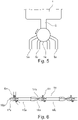
- figure 5 shows a variant of the invention in which the main extraction line 2 opens into a distributor 14 and the individual extraction lines 5a, 5b, etc. branch out from the distributor 14 in a star shape.
- the distributor 14 has a rotary switch which is designed in such a way that it can only be turned counterclockwise, as indicated by an arrow in the figure.
- a line is arranged in the drum of the rotary switch, so that only one individual removal line 5a, 5b, etc. can be released at a time.
- the individual extraction lines are provided with extraction connections and clamps fitted like this related to figure 1 was explained in more detail.
- figure 6 12 shows a variant of the invention with a line system consisting of a sampling line 15 with a plurality of sampling sectors 16a, 16b, etc. arranged in series, which are connected to one another by means of connectors 17a, 17b, etc.
- the extraction line 15 is at her in the figure 6 right end connected to the solution bag, like this related to figure 1 was declared for the main withdrawal line.
- the connectors 17a, 17b, etc. each include extraction ports 6a, 6b, etc., which as in connection with FIG figure 2 are declared trained.
- the connectors 17a, 17b, etc. each include a predetermined separation point 18a, 18b, etc., in order to be able to uncouple the extraction sectors 16a, 16b, etc.
- the connector 17b can be cut off at the predetermined separation point 18b after the extraction port 6a has been in use for a treatment and this use has ended.
- the connection at the predetermined separation points 18a, 18b, etc. can in principle be cut in any manner, for example by breaking, with the predetermined separation points 18a, 18b, etc. preferably being designed in such a way that the line leading to the decoupled sector is closed during decoupling, to prevent fresh Diasys solution from flowing out.
- the sleeve 19 is designed in such a way that, in the axial direction of the connection 6, it extends from an in Figure 7a shown open position in an in Figure 7c shown closed position can be pushed, wherein in the closed position of the extraction port 6 is blocked.
- the closed position is irreversible, since the sleeve 19 has a latching lug, not shown in detail in the figure, which in the closed position comes to rest behind or in the figure to the right of a latching projection, also not shown in detail in the figure.
- the sleeve 19 is biased by a spring 20 towards the closed position.
Landscapes
- Health & Medical Sciences (AREA)
- Heart & Thoracic Surgery (AREA)
- Urology & Nephrology (AREA)
- Emergency Medicine (AREA)
- Public Health (AREA)
- Engineering & Computer Science (AREA)
- Anesthesiology (AREA)
- Biomedical Technology (AREA)
- Hematology (AREA)
- Life Sciences & Earth Sciences (AREA)
- Animal Behavior & Ethology (AREA)
- General Health & Medical Sciences (AREA)
- Veterinary Medicine (AREA)
- Vascular Medicine (AREA)
- Pulmonology (AREA)
- External Artificial Organs (AREA)
Description
Die Erfindung betrifft eine Vorrichtung enthaltend eine Dialyselösung oder ein Dialyselösungskonzentrat, vorzugsweise zur Verwendung in der Peritonealdialyse, mit einem Aufnahmebehältnis, das ein Lösungsvolumen fassen kann, welches für wenigstens zwei Behandlungen bestimmt ist.The invention relates to a device containing a dialysis solution or a dialysis solution concentrate, preferably for use in peritoneal dialysis, with a receptacle that can hold a volume of solution intended for at least two treatments.
Insbesondere im Bereich der Peritonealdialyse ist es üblich, dem Patienten Lösungsbeutel zur Verfügung zu stellen, die mit einer für den Patienten geeigneten Dialyselösung befüllt sind. Diese Lösungsbeutel schließt der Patient dann selbsttätig oder mit Unterstützung von medizinischem Fachpersonal an einen Einlaufschlauch, d.h. an den Patientenkatheter an, um das Peritoneum mit der Lösung zu füllen.Particularly in the field of peritoneal dialysis, it is customary to provide the patient with solution bags that are filled with a dialysis solution suitable for the patient. The patient then connects this solution bag to an inflow tube, i.e. to the patient catheter, either independently or with the support of medical professionals, in order to fill the peritoneum with the solution.
Die Dialyselösung muss typischerweise in fertig zubereitetem Zustand zum Haus des Patienten transportiert werden.
Es wäre wünschenswert, ein Lösungsvolumen für mehrere Behandlungen in einem Behältnis, beispielsweise Beutel unterzubringen, um so eine Abfallreduktion erreichen zu können und den Herstellungsprozess und die Qualitätskontrolle insofern vereinfachen zu können, dass weniger Behältnisse befüllt werden müssen. Auch der Transport und die Handhabung können für den Patienten unter Umständen einfacher sein, wenn lediglich ein Behältnis hantiert werden muss.It would be desirable to accommodate a solution volume for several treatments in one container, for example a bag, in order to be able to achieve a reduction in waste and to be able to simplify the manufacturing process and quality control in that fewer containers have to be filled. Also transport and handling can sometimes be easier for the patient if only one container has to be handled.
In der
Aufgabe der Erfindung ist es, ein geeignetes Anschlusskonzept zur mehrmaligen Entnahme von Dialyselösung aus demselben Aufnahmebehältnis aufzufinden, bei dem insbesondere auch nach der ersten Entnahme und weiteren Entnahmen die Sterilität des Entnahmeanschlusses sicher gewährleistet ist.The object of the invention is to find a suitable connection concept for repeated removal of dialysis solution from the same receptacle, in which the sterility of the removal connection is reliably guaranteed, especially after the first removal and further removals.
Vor diesem Hintergrund betrifft die Erfindung eine Vorrichtung enthaltend eine Dialyselösung oder ein Dialyselösungskonzentrat, vorzugsweise zur Verwendung in der Peritonealdialyse, mit einem Aufnahmebehältnis, das ein Lösungsvolumen fassen kann, welches für wenigstens zwei Behandlungen bestimmt ist, wobei die Vorrichtung mehrere Entnahmeanschlüsse zur Entnahme der Dialyselösung aus dem Aufnahmebehältnis aufweist und die Entnahmeanschlüsse eine Doppelversicherung aufweisen, die den Entnahmeanschluss nach Verwendung irreversibel verschließt.Against this background, the invention relates to a device containing a dialysis solution or a dialysis solution concentrate, preferably for use in peritoneal dialysis, with a receptacle that can hold a volume of solution intended for at least two treatments, the device having a plurality of extraction connections for removing the dialysis solution has the receiving container and the extraction connections have a double insurance that irreversibly closes the extraction connection after use.
Unter einer Behandung wird im Zusammenhang mit der Peritonealdialyse eine vollständige oder teilweise Füllung des Bauchraums des Patienten verstanden. Unter einem Entnahmeanschluss wird im gegebenen Zusammenhang eine Schnittstelle zum direkten oder mittelbaren Anschließen der in den Bauchraum des Patienten führenden Leitung, d.h. dem Patientenkatheter verstanden. Der Entnahmeanschluss kann zu diesem Zweck beispielsweise mit einem Luer-Konnektor versehen sein.In connection with peritoneal dialysis, a treatment is understood to mean a complete or partial filling of the patient's abdomen. In the given context, a withdrawal connection is understood as an interface for the direct or indirect connection of the line leading into the abdominal cavity of the patient, ie the patient catheter. For this purpose, the removal connection can be provided with a Luer connector, for example.
Durch die Mehrzahl an Anschlüssen kann bei jeder von mehreren Entnahmen von Dialyselösung aus dem Aufnahmebehältnis ein frischer Entnahmeanschluss verwendet werden.Due to the plurality of connections, a fresh removal connection can be used for each of several removals of dialysis solution from the receptacle.
Das Aufnahmebehältnis kann ein Volumen von größer 5 Litern, größer 10 Litern oder auch größer 20 Litern aufweist. Das typischerweise im Rahmen einer Einzelbehandlung benötigte Volumen liegt in der Größenordnung von etwa 2 Litern. Die Anzahl der Anschlüsse kann auf die Größe des Aufnahmebehältnisses abgestimmt sein. Beispielsweise kann die Vorrichtung wenigstens einen Entnahmeanschluss pro zwei Liter Volumen des Aufnahmebehältnisses aufweisen.The receptacle can have a volume of more than 5 liters, more than 10 liters or even more than 20 liters. The volume typically required in a single treatment is of the order of about 2 liters. The number of connections can be matched to the size of the receptacle. For example, the device can have at least one removal connection per two liter volume of the receptacle.
Außer den Anschlüssen zur Entnahme der Dialyselösung weist das Aufnahmebehältnis typischerweise einen Befüllanschluss zum Befüllen mit Dialyselösung auf.In addition to the connections for removing the dialysis solution, the receptacle typically has a filling connection for filling with dialysis solution.
Bei dem Aufnahmebehältnis kann es sich um einen flexiblen Beutel oder um einen starren Behälter handeln. Im Falle eines starren Behälters kann ein Druckausgleichsventil vorgesehen sein. Es kann sich auch um einen flexiblen und vorzugsweise elastischen Beutel handeln, der in einem starren Behälter gelagert wird. Bei der Befüllung des Beutels füllt ein solcher Beutel idealerweise den Raum des umgebenden starren Behälters weitestgehend aus. Eine derartige Bag-In-Box-Verpackung hat den Vorteil, dass der typischerweise als Disposable ausgeführte Innenbeutel durch die Umverpackung vor mechanischen Einflüssen geschützt wird. Die mechanische Robustheit des Lösungsbeutels, hier Innenbeutels verliert gegenüber vorbekannten Lösungen an Bedeutung, wodurch eine materialsparende und kostengünstigere Ausführung ermöglicht wird. Insbesondere aufgrund der Tatsache, dass es sich bei Lösungsbeuteln typischerweise um Einwegprodukte handelt, ist die Kostenersparnis und die Abfallersparnis erheblich.The receptacle can be a flexible bag or a rigid container. In the case of a rigid container, a pressure equalizing valve can be provided. It can also be a flexible and preferably elastic bag stored in a rigid container. When the bag is being filled, such a bag ideally fills the space of the surrounding rigid container as far as possible. Such a bag-in-box packaging has the advantage that the inner bag, which is typically designed as a disposable, is protected from mechanical influences by the outer packaging. The mechanical robustness of the solution bag, in this case the inner bag, is less important than previously known solutions, which allows for a material-saving and more cost-effective design. In particular due to the fact that solution bags are typically disposable products, the cost savings and waste savings are significant.
Der Behälter kann transparent sein oder ein transparentes Sichtfenster aufweisen. Gegebenenfalls können Füllstandsmarkierungen vorgesehen sein. Die Vorrichtung kann gegebenenfalls ein Dosierbehältnis aufweisen, das zwischen den Entnahmeanschlüssen und dem Aufnahmebehältnis angeordnet ist, um die Dosierung der richtigen Flüssigkeitsmenge für eine Behandlung zu vereinfachen.The container can be transparent or have a transparent viewing window. If necessary, level markings can be provided. The device can optionally have a dosing container between the sampling ports and the receptacle to facilitate dosing the correct amount of liquid for a treatment.
In einer Ausführungsform ist vorgesehen,dass jedem Entnahmeanschluss ein Ventil und ein Drainageanschluss zugeordnet ist. So kann jeder Entnahmeanschluss auch für einen Draining-Vorgang genützt werden. Beispiele geeigneter Ventile umfassen Drehventile oder 3/3-Wege-Ventile. Nach Anschließen der in den Bauchraum des Patienten führenden Leitung an den Entnahmeanschluss kann das zuvor geschlossene Ventil zunächst so eingestellt werden oder das Ventil so eingestellt bleiben, dass verbrauchte Dialyselösung durch den Drainageanschluss bzw. eine daran angeschlossene Drainage-Leitung abfließt. Sodann kann das Ventil so eingestellt werden, dass frische Dialyselösung aus dem Aufnahmebehältnis in den Baurchraum des Patienten fließen kann. Gegebenenfalls kann zum Entlüften der Leitung auch eine Ventilstellung angenommen werden, in der ein Fluss von Dialyselösung aus dem Aufnahmebehältnis in den Drainageanschluss bzw. eine daran angeschlossene Drainage-Leitung ermöglicht wird.In one embodiment it is provided that a valve and a drainage connection are assigned to each removal connection. In this way, each removal connection can also be used for a drainage process. Examples of suitable valves include rotary valves or 3/3-way valves. After connecting the line leading into the patient's abdominal cavity to the removal connection, the previously closed valve can initially be set or the valve can remain set in such a way that used dialysis solution flows out through the drainage connection or a drainage line connected thereto. The valve can then be adjusted in such a way that fresh dialysis solution can flow from the receptacle into the patient's abdomen. If necessary, to vent the line, a valve position can also be assumed in which a flow of dialysis solution from the receiving container into the drainage connection or a drainage line connected thereto is made possible.
In einer Ausführungsform ist vorgesehen,dass die Vorrichtung eine Entnahmehauptleitung aufweist, die mit dem Aufnahmebehältnis in Verbindung steht und von der mehrere Entnahmeeinzelleitungen mit den Entnahmeanschlüssen abgehen. Alternativ oder zusätzlich kann vorgesehen sein, dass in den Entnahmeeinzelleitungen jeweils Schließmittel angeordnet sind, mit denen die Entnahmeeinzelleitungen verschlossen werden können. Bei den Schließmitteln kann es sich beispielsweise um Klemmen handeln, mit denen die jeweilige Leitung abgeklemmt werden kann. In einer Ausführungsform ist vorgesehen, dass die Schließmittel und vorzugsweise Klemmen so ausgebildet sind, dass die jeweilige Leitung irreversibel verschlossen werden kann. In einer Ausführungsform ist vorgesehen, dass die Schließmittel so ausgebildet sind, dass sie sich bei oder nach einer Abkopplung der Entnahmeeinzelleitung vom Patienten automatisch verschließen. In einer Ausführungsform sind die Schließmittel derart ausgebildet, dass eine erneute Öffnung der benutzten Entnahmeeinzelleitung unmöglich ist.In one embodiment it is provided that the device has a main extraction line which is connected to the receiving container and from which several individual extraction lines with extraction connections branch off. Alternatively or additionally, it can be provided that closing means are arranged in the individual extraction lines, with which the individual extraction lines can be closed. The closing means can be clamps, for example, with which the respective line can be disconnected. In one embodiment it is provided that the closing means and preferably clamps are designed in such a way that the respective line can be closed irreversibly. In one embodiment it is provided that the closing means are designed in such a way that they close automatically when or after the individual removal line is disconnected from the patient. In one embodiment, the closing means are designed in such a way that it is impossible to reopen the single extraction line that has been used.
In einer Ausführungsform ist vorgesehen,dass die Entnahmeeinzelleitungen an unterschiedlichen Verzweigungspunkten von der Entnahmehauptleitung abzweigen, die über die Länge der Entnahmehauptleitung verteilt sind. Das Leitungssystem bestehend aus der Entnahmehauptleitung und den Entnahmeeinzelleitungen hat in dieser Ausführungsform eine Baumstruktur, wobei die Entnahmehauptleitung dem Stamm und die Entnahmeeinzelleitungen den Ästen entsprechen. Jedem Entnahmeanschluss kann eine Einzelleitung zugeordnet sein.In one embodiment it is provided that the individual extraction lines branch off from the main extraction line at different branching points, which are distributed over the length of the main extraction line. The line system consisting of the main extraction line and the individual extraction lines has a tree structure in this embodiment, with the main extraction line corresponding to the trunk and the individual extraction lines to the branches. An individual line can be assigned to each extraction connection.
In einer Ausführungsform ist vorgesehen,dass in der Entnahmehauptleitung jeweils Schließmittel zwischen aufeinanderfolgenden Abzweigungspunkten der Entnahmeeinzelleitung angeordnet sind, mit denen die Entnahmehauptleitung verschlossen werden können.In one embodiment it is provided that closing means are arranged in the main extraction line between successive branching points of the individual extraction line, with which the main extraction line can be closed.
Die Schließmittel können wir oben näher beschrieben ausgebildet sein.The closing means can be designed as described in more detail above.
In der Anwendung kann vorgesehen sein, bei der ersten Flüssigkeitsentnahme denjenigen Entnahmeanschluss zu verwenden, der an der letzten, d.h., der am weitesten von dem Aufnahmebehältnis entfernten Entnahmeeinzelleitung sitzt. Nach Beendigung dieses Vorgangs kann die betreffende Entnahmeeinzelleitung unter Verwendung eines Schließmittels, z.B. einer Klemme, eines Ventils oder eines Hahns verschlossen werden. Alternativ kann die Entnahmehauptleitung an einer Stelle zwischen den Abzeigungen der letzten und vorletzten Entnahmeeinzelleitungen unter Verwendung eines Schließmittels verschlossen werden. Bei der zweiten Flüssigkeitsentnahme kann sodann der vorletzte Entnahmeanschluss verwendet werden und im Anschluss auch dieser durch Verschließen der Entnahmeeinzelleitung oder Entnahmehauptleitung abgekoppelt werden. Dieser Vorgang kann wiederholt werden, bis der letzte Entnahmeanschluss an der letzten, d.h., am nähesten am Aufnahmebehältnis befindlichen Entnahmeeinzelleitung benutzt oder die gesamte Dialyselösung im Aufnahmebehältnis verbraucht wurde. Eine Abkopplung an der Entnahmehauptleitung kann den Vorteil haben, dass weniger Totvolumen entsteht.In the application, provision can be made for the first liquid withdrawal to use that withdrawal connection which is located on the last individual withdrawal line, ie that which is furthest away from the receiving container. After the completion of this process, the extraction line in question can be closed using a closing means, eg a clamp, a valve or a cock. Alternatively, the main bleed line can be closed off at a point between the branches of the last and penultimate bleed individual lines using a closing means. The penultimate withdrawal connection can then be used for the second withdrawal of liquid and this can then also be uncoupled by closing the individual withdrawal line or the main withdrawal line. This process can be repeated until the last extraction connection on the last single extraction line, ie the one closest to the receptacle, has been used or the entire dialysis solution in the receptacle has been used up. A decoupling at the main sampling line can have the advantage that less dead volume arises.
In einer Ausführungsform ist vorgesehen,dass die Entnahmehauptleitung in einen Verteiler mündet und die Entnahmeeinzelleitungen sternförmig von dem Verteiler abgehen. Der Verteiler kann einen Schalter aufweisen, der so ausgebildet ist, dass immer nur die Freigabe einer einzelnen Entnahmeeinzelleitung möglich ist und dass nur eine solche Entnahmeeinzelleitung freigegeben werden kann, welche zuvor noch nicht verwendet wurde. Ein Beispiel eines geeigneten Schalters umfasst einen Drehschalter, der nur in eine Richtung gedreht werden kann.In one embodiment it is provided that the main extraction line opens into a distributor and the individual extraction lines leave the distributor in a star shape. The distributor can have a switch which is designed in such a way that it is only ever possible to release a single individual extraction line and that only such an individual extraction line can be released which has not been used before. An example of a suitable switch includes a rotary switch that can only be rotated in one direction.
Am vorlaufseitigen Ende der Entnahmehauptleitung kann ein Verbindungsmechanismus vorgesehen sein, der ausgebildet ist, um das Leitungssystem insgesamt von dem Aufnahmebehältnis abkoppeln zu können. So kann beispielsweise entweder das Aufnahmebehältnis oder das Leitungssystem wiederverwendet werden.A connection mechanism can be provided at the upstream end of the main extraction line, which is designed to be able to uncouple the line system as a whole from the receiving container. For example, either the receptacle or the line system can be reused.
Gegebenenfalls kann die Entnahmehauptleitung und/oder können die Entnahmeeinzelleitungen Rückschlagventile als zusätzliche Kontaminationsbarriere aufweisen.If necessary, the main extraction line and/or the individual extraction lines can have non-return valves as an additional contamination barrier.
In einer Ausführungsform ist vorgesehen,dass die Vorrichtung eine Entnahmeleitung aufweist, an der die Entnahmeanschlüsse in Serie angeordnet sind, wobei vorzugsweise vorgesehen ist, dass die Entnahmeleitung in mehrere abkoppelbare Sektoren unterteilt ist und in jedem der Sektoren ein Entnahmeanschluss angeordnet ist. In den einzelnen Sektoren können wie oben beschriebene Schließmittel angeordnet sein, um die Sektoren abkoppeln zu können. Die Sektoren können anhand von Verbindern miteinander verbunden sein, die Solltrennstellen aufweisen, um einen Sektor mit einem verbrauchten Entnahmeanschluss abzutrennen. Vorzugsweise sind die Solltrennstellen so ausgebildet, dass der Durchlass beim Trennen verschlossen wird.In one embodiment it is provided that the device has a sampling line on which the sampling connections are arranged in series, it being preferably provided that the sampling line is divided into several detachable sectors and a sampling connection is arranged in each of the sectors. Closing means as described above can be arranged in the individual sectors in order to be able to decouple the sectors. The sectors may be interconnected by connectors having predetermined disconnect points to disconnect a sector with a used bleed port. The predetermined separation points are preferably designed in such a way that the passage is closed when the separation occurs.
In einer Ausführungsform ist vorgesehen,dass die Entnahmeanschlüsse mit luftdichten Umhüllungen einzeln versiegelt sind, wobei vorzugsweise vorgesehen ist, dass eine der Anzahl der Entnahmeanschlüssen entsprechende Anzahl an Umhüllungen vorhanden ist, wobei eine innerste Umhüllung einen Entnahmeanschluss und jede weitere Umhüllung die bestehende Umhüllung und einen weiteren Entnahmeanschluss umschließt. Geeignete Umhüllungen umfassen beispielsweise Kunststoffbeutel, Kappen oder dergleichen. Es kann vorgesehen sein, dass die Umhüllungen dem Prinzip einer russischen Puppe folgen. Wird die äußerste Umhüllung geöffnet, wird ein Entnahmeanschluss sowie die nächste Umhüllung freigegeben, die alle weiteren Entnahmeanschlüsse versiegelt. Wird diese nächste Umhüllung geöffnet, wird ein weiterer Entnahmeanschluss und die übernächste Umhüllung freigegeben, und so weiter. Erst nach Öffnen der innersten Umhüllung wird der letzte Entnahmeanschluss freigegeben. Durch diese Art der Versiegelung kann die Gefahr der Verwechslung von bereits benutzten und frischen Anschlüssen minimiert werden. Im Falle des oben vorgestellten Leitungssystems mit Entnahmehauptleitung und Entnahmeeinzelleitungen in Baumstruktur kann der letzte Entnahmeanschluss an der letzten, d.h., am nähesten am Aufnahmebehältnis befindlichen Entnahmeeinzelleitung von allen und der erste Entnahmeanschluss an der ersten, d.h., am weitesten vom Aufnahmebehältnis entfernten Entnahmeeinzelleitung von nur der äußersten Umhüllung umgeben sein.In one embodiment it is provided that the extraction ports are individually sealed with airtight envelopes, it being preferably provided that that there is a number of casings corresponding to the number of tapping ports, with an innermost casing enclosing a tapping port and each additional casing enclosing the existing casing and a further tapping port. Suitable coverings include, for example, plastic bags, caps or the like. It can be provided that the covers follow the principle of a Russian doll. Opening the outermost wrapper reveals a bleed port and the next wrapper that seals all other bleed ports. Opening this next enclosure will expose another extraction port and the next but one enclosure, and so on. The last removal connection is only released after the innermost cover has been opened. This type of sealing minimizes the risk of confusing used and fresh connections. In the case of the line system presented above with a main extraction line and individual extraction lines in a tree structure, the last extraction connection can be on the last extraction line, i.e. the one closest to the receiving container, and the first extraction connection on the first extraction line, i.e. the furthest away from the receiving container, can only be on the outermost be surrounded by an envelope.
Bei der Doppelverwendungssicherung kann beispielsweise eine bewegliche Hülse umfassen, die von einer offenen Stellung in eine geschlossene Stellung bewegt werden kann und in geschlossener Stellung den Entnahmeanschluss blockiert. Die Hülse kann beispielsweise so ausgebildet sein, dass sie in axialer Richtung des Anschlusses von einer offenen Stellung in eine geschlossene Stellung verschoben werden kann. Es kann vorgesehen sein, dass die geschlossene Stellung irreversibel ist, d.h., dass die Hülse nicht mehr von der geschlossenen in die offene Stellung zurückverschoben werden kann. Dieser Arrest kann beispielsweise durch einen Rastvorsprung und eine Rastnase realisisert sein. So kann eine unerwünschte Mehrfachverwendung desselben Anschlusses effektiv vermieden werden. Die Hülse kann beispielsweise gegen die geschlossene Stellung vorgespannt sein, sodass sie nach Aufbrechen eines Halteelements automatisch in die geschlossene Stellung übergeführt wird. Das Halteelement kann so ausgebildet sein, dass es bei Ankopplung der in den Bauchraum des Patienten führenden Leitung aufgebrochen wird. Die Hülse wird dann so lange von der Patientenleitung gehalten, wie diese angeschlossen ist. Bei Abnahme schließt die Hülse irreversibel.For example, the dual-use safeguard may include a moveable sleeve that is moveable from an open position to a closed position and, when closed, blocks the extraction port. For example, the sleeve can be designed in such a way that it can be displaced from an open position to a closed position in the axial direction of the connection. Provision can be made for the closed position to be irreversible, ie the sleeve can no longer be pushed back from the closed to the open position. This arrest can be implemented, for example, by a latching projection and a latching lug. This effectively eliminates unwanted multiple use of the same port be avoided. For example, the sleeve can be prestressed against the closed position, so that it is automatically transferred into the closed position after a holding element has been broken open. The holding element can be designed in such a way that it is broken open when the line leading into the abdominal cavity of the patient is coupled. The sleeve is then held by the patient line for as long as it is connected. When removed, the sleeve closes irreversibly.
Das Behältnis kann keine gebrauchsfertige Dialyselösung sondern lediglich ein Konzentrat enthalten. Die gebrauchsfertige Dialyselösung kann vor Ort durch Auffüllen des Behältnisses mit aufgereinigtem sterilen Wasser, beispielsweise aus einer Revers-Osmose-Anlage, hergestellt werden. In einer solchen Ausführungsform besitzt das Behältnis auch eine Zuleitung für Flüssigkeiten, wobei die Zuleitung vorzugsweise verschließbar ist. Das Konzentrat kann in dem Behältnis frei oder in einem separaten Kompartiment vorgelegt werden. Es können auch mehrere verschiedene Konzentrate in mehreren Kompartimenten vorgelegt werden. Durch eine Brechverbindung kann Aufbrechen eine fluide Verbindung zwischen den Konzentratkompartimenten und einem Mischkompartiment hergestellt werden. Als Brechverbindung eignen sich für den Fall, dass das Behältnis ein Folienbeutel ist beispielsweise peelfähige Schweißnähte.The container cannot contain a ready-to-use dialysis solution but only a concentrate. The ready-to-use dialysis solution can be prepared on site by filling the container with purified, sterile water, for example from a reverse osmosis system. In such an embodiment, the container also has a supply line for liquids, the supply line preferably being closable. The concentrate can be placed freely in the container or in a separate compartment. Several different concentrates can also be placed in several compartments. A breakable connection can be used to create a fluid connection between the concentrate compartments and a mixing compartment. In the event that the container is a film bag, peelable welded seams, for example, are suitable as breakable connections.
Weitere Einzelheiten und Vorteile der Erfindung ergeben sich aus den nachfolgend anhand der Figuren beschriebenen Ausführungsbeispielen. In den Figuren zeigen:
- Figur 1:
- eine erfindungsgemäße Vorrichtung mit einem Leitungssystem bestehend aus einer Entnahmehauptleitung und mehreren Entnahmeeinzelleitungen in Baumstruktur;
- Figur 2:
- eine Variante eines Entnahmeanschlusses mit Drainage-Anschluss und 3-Wege-Ventil;
- Figur 3:
- eine Variante eines Entnahmeanschlusses mit Drainage-Anschluss und Drehschalter;
- Figur 4:
- die
Vorrichtung der Figur 1 mit einer Matryoschka-Umhüllung der Entnahmeanschlüsse; - Figur 5:
- eine erfindungsgemäße Vorrichtung mit einem Leitungssystem bestehend aus einer Entnahmehauptleitung und mehreren Entnahmeeinzelleitungen in Sternstruktur;
- Figur 6:
- eine erfindungsgemäße Vorrichtung mit einem Leitungssystem bestehend aus einer Entnahmeleitung mit mehreren in Serie angeordneten Entnahmesektoren; und
- Figur 7:
- eine Variante eines Entnahmeanschlusses mit Doppelverwendungssicherung.
- Figure 1:
- a device according to the invention with a line system consisting of a main extraction line and several individual extraction lines in a tree structure;
- Figure 2:
- a variant of a withdrawal connection with drainage connection and 3-way valve;
- Figure 3:
- a variant of a withdrawal connection with drainage connection and rotary switch;
- Figure 4:
- the device of
figure 1 with a matryoshka covering of the extraction connectors; - Figure 5:
- a device according to the invention with a line system consisting of a main extraction line and several individual extraction lines in a star structure;
- Figure 6:
- a device according to the invention with a line system consisting of an extraction line with a plurality of extraction sectors arranged in series; and
- Figure 7:
- a variant of a tapping connection with dual-use protection.
Eine erste Variante einer erfindungsgsmäßen Vorrichtung ist in
Von der Entnahmehauptleitung 2 zweigt an unterschiedlichen Verweigungspunkten 4a, 4b, etc., die in Serie über die Länge der Entnahmehauptleitung verteilt sind, jeweils eine Entnahmeeinzelleitung 5a, 5b, etc. ab. Jede der Entnahmeeinzelleitungen weist an dessen Ende einen Entnahmeanschluss 6a, 6b, etc. auf und ist ferner mit einer Klemme 7a, 7b, etc. versehen.An
In der Entnahmehauptleitung 2 ist zwischen dem am nähesten am Beutel befindlichen Verzweigungspunkt 4z und dem Verbindungselementepaar 3 eine Hauptklemme 8 vorgesehen.A
Die einzelnen Entnahmeanschlüsse 6 können so ausgebildet sein wie in
Die einzelnen Entnahmeanschlüsse 6 können auch so ausgebildet sein wie in
In der Anwendung der in
Auch in den Varianten der
Letztlich zeigt
Claims (10)
- An apparatus containing a dialysis solution or a dialysis solution concentrate, preferably for use in peritoneal dialysis, comprising a reception container that can accommodate a solution volume which is intended for at least two treatments,
characterized in that
the apparatus has a plurality of extraction ports for extracting the dialysis solution from the reception container; and in that the extraction ports have a security against double use that irreversibly closes the extraction port after use. - An apparatus in accordance with claim 1, characterized in that a valve and a drainage port are associated with each extraction port.
- An apparatus in accordance with one of the preceding claims, characterized in that the apparatus has a main extraction line that is connected to the reception container and from which a plurality of single extraction lines having the extraction ports lead off.
- An apparatus in accordance with claim 3, characterized in that respective closing means by which the single extraction lines can be closed are arranged in the single extraction lines.
- An apparatus in accordance with claim 4, characterized in that the closing means are configured such that they close automatically on or after a decoupling of the single extraction line from the patient.
- An apparatus in accordance with one of the claims 3 to 5, characterized in that the single extraction lines branch off from the main extraction line at different branch points that are distributed over the length of the main extraction line.
- An apparatus in accordance with claim 6, characterized in that respective closing means are arranged in the main extraction line between branch points of the single extraction line that follow one another and with which the main extraction line can be closed.
- An apparatus in accordance with one of the claims 3 to 5, characterized in that the main extraction line opens into a distributor and the single extraction lines lead off from the distributor in star shape.
- An apparatus in accordance with claim 1 or claim 2, characterized in that the apparatus has an extraction line at which the extraction ports are arranged in series, with provision preferably being made that the extraction line is divided into a plurality of decouplable sectors and an extraction port is arranged in each of the sectors.
- An apparatus in accordance with one of the preceding claims, characterized in that the extraction ports are individually sealed by airtight sheaths, with provision preferably being made that a number of sheaths corresponding to the number of extraction ports is present, with an innermost sheath surrounding an extraction port and every further sheath surrounding the existing sheath and a further extraction port.
Applications Claiming Priority (2)
| Application Number | Priority Date | Filing Date | Title |
|---|---|---|---|
| DE102018103937.9A DE102018103937A1 (en) | 2018-02-21 | 2018-02-21 | Device containing dialysis solution or dialysis solution concentrate |
| PCT/EP2019/053641 WO2019162178A1 (en) | 2018-02-21 | 2019-02-14 | Device comprising a dialysis solution or a dialysis solution concentrate |
Publications (2)
| Publication Number | Publication Date |
|---|---|
| EP3755397A1 EP3755397A1 (en) | 2020-12-30 |
| EP3755397B1 true EP3755397B1 (en) | 2022-11-02 |
Family
ID=65516508
Family Applications (1)
| Application Number | Title | Priority Date | Filing Date |
|---|---|---|---|
| EP19706456.1A Active EP3755397B1 (en) | 2018-02-21 | 2019-02-14 | Device containing dialysate or dialysate concentrate |
Country Status (8)
| Country | Link |
|---|---|
| US (1) | US20200397970A1 (en) |
| EP (1) | EP3755397B1 (en) |
| JP (1) | JP7350758B2 (en) |
| CN (1) | CN111886036B (en) |
| BR (1) | BR112020017174A2 (en) |
| DE (1) | DE102018103937A1 (en) |
| ES (1) | ES2937358T3 (en) |
| WO (1) | WO2019162178A1 (en) |
Family Cites Families (34)
| Publication number | Priority date | Publication date | Assignee | Title |
|---|---|---|---|---|
| US4298001A (en) * | 1980-08-08 | 1981-11-03 | Hargest Iii Thomas S | Fluid flow connector unit and method |
| SE455470B (en) * | 1981-06-23 | 1988-07-18 | Terumo Corp | CONNECTING TWO HOSE FOR MEDICAL, THERAPEUTICAL USE HOSE |
| US4950230A (en) * | 1987-03-19 | 1990-08-21 | Delmed, Inc. | Method and apparatus for bagless continuous ambulatory peritoneal dialysis |
| US5053003A (en) * | 1989-04-18 | 1991-10-01 | Dadson Joseph E | Method and apparatus for peritoneal dialysis using a "Y" tubing set |
| US5497763A (en) * | 1993-05-21 | 1996-03-12 | Aradigm Corporation | Disposable package for intrapulmonary delivery of aerosolized formulations |
| DE19520916A1 (en) * | 1995-06-08 | 1997-01-09 | Schael Wilfried | Device for supplying haemodialysis apparatus with fluid - has two channels with one at high pressure and other at low, with high pressure channel used for withdrawing dialysis fluid and low pressure channel for returning surplus fluid from high pressure channel. |
| JP3898313B2 (en) * | 1997-11-27 | 2007-03-28 | 積水化学工業株式会社 | Medical fittings |
| SE512349C2 (en) * | 1997-11-28 | 2000-03-06 | Gambro Lundia Ab | Multi-chamber container for medical solution, procedure for preparation of medical solution for peritoneal dialysis and use of such container for preparation of medical solution |
| JP4543335B2 (en) * | 1998-07-13 | 2010-09-15 | 株式会社ジェイ・エム・エス | Medical tube connector device |
| TW477696B (en) * | 1998-07-29 | 2002-03-01 | Mesibo As | A bag system for collecting and storing blood and a method therefor |
| AU2000239905A1 (en) * | 2000-02-28 | 2001-09-12 | Gambro Lundia A.B. | Method and device for pd cyclers |
| US7384416B2 (en) * | 2002-08-12 | 2008-06-10 | Macopharma | Device and method for irreversible closure of fluid communication in a container system |
| JP2006052863A (en) * | 2004-08-09 | 2006-02-23 | Toshiba Kyaria Kk | Pipe-connecting joint of refrigeration cycle device |
| FR2909649B1 (en) * | 2006-12-11 | 2009-07-03 | Maurice Granger | DISPOSABLE TOOL FOR WIPING MATERIAL COIL AND WIPING MATERIAL DISPENSER RECEIVING SUCH A TIP |
| DE102007017816A1 (en) * | 2007-04-16 | 2008-10-30 | Hecht Anlagenbau Gmbh | Adapter device for containers for contamination-free removal of their contents |
| CN201052268Y (en) * | 2007-07-11 | 2008-04-30 | 张厚勤 | Blood transfusion bag |
| GB0805297D0 (en) * | 2008-03-20 | 2008-04-30 | Scottish & Newcastle Plc | Beverage dispense apparatus |
| US20100217179A1 (en) | 2009-02-20 | 2010-08-26 | Baxter International Inc. | Bulk delivery peritoneal dialysis system and method |
| CN201414968Y (en) * | 2009-05-31 | 2010-03-03 | 广东龙心医疗器械有限公司 | Disposable safe venous retention needle |
| EP2258418A1 (en) * | 2009-06-05 | 2010-12-08 | Fresenius Medical Care Deutschland GmbH | Device for collecting samples |
| SG181569A1 (en) * | 2009-12-07 | 2012-07-30 | Advanced Tech Materials | Configurable port fitment, kit, and related methods |
| EP2332610B1 (en) * | 2009-12-10 | 2013-02-13 | Fresenius Kabi Deutschland GmbH | Connection system for food containers for enteral feeding |
| DE102009060330A1 (en) * | 2009-12-23 | 2011-06-30 | Fresenius Medical Care Deutschland GmbH, 61352 | Dialysis machine, in particular peritoneal dialysis machine |
| US20110251489A1 (en) * | 2010-04-07 | 2011-10-13 | Physiosonics, Inc. | Ultrasound monitoring systems, methods and components |
| DE102011008223B4 (en) * | 2011-01-10 | 2019-07-04 | Fresenius Medical Care Deutschland Gmbh | Dialysis treatment unit |
| JP5818538B2 (en) * | 2011-06-30 | 2015-11-18 | 株式会社トップ | Indwelling needle |
| CN202699174U (en) * | 2012-08-01 | 2013-01-30 | 郑州信翰科技开发有限公司 | Medical probe isolating jacket and safety isolating jacket device provided with medical probe isolating jacket |
| JP6334673B2 (en) * | 2013-03-14 | 2018-05-30 | バクスター・インターナショナル・インコーポレイテッドBaxter International Incorp0Rated | System and method for peritoneal dialysis exchange with reusable actuation unit |
| EP3107614B1 (en) * | 2014-02-18 | 2021-08-04 | Bayer Healthcare LLC | Multi-dose fluid delivery system |
| CN204319274U (en) * | 2014-12-16 | 2015-05-13 | 深圳市茵冠生物科技有限公司 | For feeding back the transfusion bag of cell |
| EP3034062B1 (en) * | 2014-12-19 | 2017-03-22 | Fresenius Kabi Deutschland GmbH | Connector system comprising at least two outlet ports |
| CN204745116U (en) * | 2015-07-22 | 2015-11-11 | 金华市中心医院 | A crossover sub that is used for connection center ductus venosus and ordinary drainage bag |
| CN107662757A (en) * | 2016-07-29 | 2018-02-06 | 重庆莱美药业股份有限公司 | A kind of combination cover, interface and packing container with combination cover |
| DE102017000495A1 (en) * | 2017-01-20 | 2018-07-26 | Fresenius Medical Care Deutschland Gmbh | DlALYSATKONZENTRATlON-MESSSENSORDlAGNOSE |
-
2018
- 2018-02-21 DE DE102018103937.9A patent/DE102018103937A1/en not_active Ceased
-
2019
- 2019-02-14 BR BR112020017174-3A patent/BR112020017174A2/en unknown
- 2019-02-14 EP EP19706456.1A patent/EP3755397B1/en active Active
- 2019-02-14 US US16/971,456 patent/US20200397970A1/en active Pending
- 2019-02-14 ES ES19706456T patent/ES2937358T3/en active Active
- 2019-02-14 WO PCT/EP2019/053641 patent/WO2019162178A1/en unknown
- 2019-02-14 JP JP2020544475A patent/JP7350758B2/en active Active
- 2019-02-14 CN CN201980020759.7A patent/CN111886036B/en active Active
Also Published As
| Publication number | Publication date |
|---|---|
| JP2021514268A (en) | 2021-06-10 |
| US20200397970A1 (en) | 2020-12-24 |
| ES2937358T3 (en) | 2023-03-28 |
| DE102018103937A1 (en) | 2019-08-22 |
| CN111886036B (en) | 2023-08-11 |
| BR112020017174A2 (en) | 2020-12-22 |
| CN111886036A (en) | 2020-11-03 |
| WO2019162178A1 (en) | 2019-08-29 |
| JP7350758B2 (en) | 2023-09-26 |
| EP3755397A1 (en) | 2020-12-30 |
Similar Documents
| Publication | Publication Date | Title |
|---|---|---|
| EP0198407B1 (en) | Connector for peritoneal dialysis | |
| DE3513204C2 (en) | ||
| DE3143329C2 (en) | Protective device for a connecting plug of medical hose systems | |
| DE2947574C2 (en) | Hose coupling for line connectors that are to be kept sterile | |
| EP2825248B1 (en) | Medical device comprising a socket unit for connecting a device for providing medical liquids | |
| DE2801438A1 (en) | DEVICE FOR TAKING BLOOD SAMPLES | |
| EP2836247B1 (en) | Recirculation device of an extracorporeal blood treatment apparatus | |
| DE2815058A1 (en) | CATHETER ARRANGEMENT | |
| DE3627231C2 (en) | Transfer device for mixing medication in different containers | |
| EP2877219A1 (en) | Mobile system for separating donor blood by means of gravitational force | |
| EP3755397B1 (en) | Device containing dialysate or dialysate concentrate | |
| DE2256748A1 (en) | CANNULES FOR INSERTING A FLEXIBLE CATHETER | |
| DE102008047068A1 (en) | Method and device for separating blood using a centrifuge | |
| EP2869868B1 (en) | Filling device of a fluid system | |
| EP2114486B1 (en) | Medical apparatus | |
| DE202011004487U1 (en) | Device for filling blood products | |
| DE60022126T2 (en) | Infusion system with several infusion bags | |
| DE3613689C2 (en) | ||
| EP1721595B1 (en) | Container for providing medical fluids | |
| DE102015117649A1 (en) | Connection kit and method for sterile connection | |
| DE102021121108A1 (en) | Multipart dialyzer | |
| WO2022194836A1 (en) | Tube connector for an infusion tube, infusion set, and method for venting an infusion tube | |
| WO2019162189A1 (en) | Container for receiving a dialysis solution | |
| EP0512281A1 (en) | Connector for a pharmaceutical solution container | |
| DE3539159A1 (en) | Device for the aseptic handling of the connectors of transfer equipment on exchange of the bags during continuous ambulatory peritoneal dialysis (CAPD), and plastic bag filled with a dialysate |
Legal Events
| Date | Code | Title | Description |
|---|---|---|---|
| STAA | Information on the status of an ep patent application or granted ep patent |
Free format text: STATUS: UNKNOWN |
|
| STAA | Information on the status of an ep patent application or granted ep patent |
Free format text: STATUS: THE INTERNATIONAL PUBLICATION HAS BEEN MADE |
|
| PUAI | Public reference made under article 153(3) epc to a published international application that has entered the european phase |
Free format text: ORIGINAL CODE: 0009012 |
|
| STAA | Information on the status of an ep patent application or granted ep patent |
Free format text: STATUS: REQUEST FOR EXAMINATION WAS MADE |
|
| 17P | Request for examination filed |
Effective date: 20200911 |
|
| AK | Designated contracting states |
Kind code of ref document: A1 Designated state(s): AL AT BE BG CH CY CZ DE DK EE ES FI FR GB GR HR HU IE IS IT LI LT LU LV MC MK MT NL NO PL PT RO RS SE SI SK SM TR |
|
| AX | Request for extension of the european patent |
Extension state: BA ME |
|
| DAV | Request for validation of the european patent (deleted) | ||
| DAX | Request for extension of the european patent (deleted) | ||
| GRAP | Despatch of communication of intention to grant a patent |
Free format text: ORIGINAL CODE: EPIDOSNIGR1 |
|
| STAA | Information on the status of an ep patent application or granted ep patent |
Free format text: STATUS: GRANT OF PATENT IS INTENDED |
|
| INTG | Intention to grant announced |
Effective date: 20220530 |
|
| GRAS | Grant fee paid |
Free format text: ORIGINAL CODE: EPIDOSNIGR3 |
|
| GRAA | (expected) grant |
Free format text: ORIGINAL CODE: 0009210 |
|
| STAA | Information on the status of an ep patent application or granted ep patent |
Free format text: STATUS: THE PATENT HAS BEEN GRANTED |
|
| AK | Designated contracting states |
Kind code of ref document: B1 Designated state(s): AL AT BE BG CH CY CZ DE DK EE ES FI FR GB GR HR HU IE IS IT LI LT LU LV MC MK MT NL NO PL PT RO RS SE SI SK SM TR |
|
| REG | Reference to a national code |
Ref country code: GB Ref legal event code: FG4D Free format text: NOT ENGLISH |
|
| REG | Reference to a national code |
Ref country code: CH Ref legal event code: EP Ref country code: AT Ref legal event code: REF Ref document number: 1528288 Country of ref document: AT Kind code of ref document: T Effective date: 20221115 |
|
| REG | Reference to a national code |
Ref country code: DE Ref legal event code: R096 Ref document number: 502019006126 Country of ref document: DE |
|
| REG | Reference to a national code |
Ref country code: IE Ref legal event code: FG4D Free format text: LANGUAGE OF EP DOCUMENT: GERMAN |
|
| REG | Reference to a national code |
Ref country code: LT Ref legal event code: MG9D |
|
| REG | Reference to a national code |
Ref country code: NL Ref legal event code: MP Effective date: 20221102 |
|
| REG | Reference to a national code |
Ref country code: ES Ref legal event code: FG2A Ref document number: 2937358 Country of ref document: ES Kind code of ref document: T3 Effective date: 20230328 |
|
| PG25 | Lapsed in a contracting state [announced via postgrant information from national office to epo] |
Ref country code: SE Free format text: LAPSE BECAUSE OF FAILURE TO SUBMIT A TRANSLATION OF THE DESCRIPTION OR TO PAY THE FEE WITHIN THE PRESCRIBED TIME-LIMIT Effective date: 20221102 Ref country code: PT Free format text: LAPSE BECAUSE OF FAILURE TO SUBMIT A TRANSLATION OF THE DESCRIPTION OR TO PAY THE FEE WITHIN THE PRESCRIBED TIME-LIMIT Effective date: 20230302 Ref country code: NO Free format text: LAPSE BECAUSE OF FAILURE TO SUBMIT A TRANSLATION OF THE DESCRIPTION OR TO PAY THE FEE WITHIN THE PRESCRIBED TIME-LIMIT Effective date: 20230202 Ref country code: LT Free format text: LAPSE BECAUSE OF FAILURE TO SUBMIT A TRANSLATION OF THE DESCRIPTION OR TO PAY THE FEE WITHIN THE PRESCRIBED TIME-LIMIT Effective date: 20221102 Ref country code: FI Free format text: LAPSE BECAUSE OF FAILURE TO SUBMIT A TRANSLATION OF THE DESCRIPTION OR TO PAY THE FEE WITHIN THE PRESCRIBED TIME-LIMIT Effective date: 20221102 |
|
| PGFP | Annual fee paid to national office [announced via postgrant information from national office to epo] |
Ref country code: FR Payment date: 20230119 Year of fee payment: 5 |
|
| PG25 | Lapsed in a contracting state [announced via postgrant information from national office to epo] |
Ref country code: RS Free format text: LAPSE BECAUSE OF FAILURE TO SUBMIT A TRANSLATION OF THE DESCRIPTION OR TO PAY THE FEE WITHIN THE PRESCRIBED TIME-LIMIT Effective date: 20221102 Ref country code: PL Free format text: LAPSE BECAUSE OF FAILURE TO SUBMIT A TRANSLATION OF THE DESCRIPTION OR TO PAY THE FEE WITHIN THE PRESCRIBED TIME-LIMIT Effective date: 20221102 Ref country code: LV Free format text: LAPSE BECAUSE OF FAILURE TO SUBMIT A TRANSLATION OF THE DESCRIPTION OR TO PAY THE FEE WITHIN THE PRESCRIBED TIME-LIMIT Effective date: 20221102 Ref country code: IS Free format text: LAPSE BECAUSE OF FAILURE TO SUBMIT A TRANSLATION OF THE DESCRIPTION OR TO PAY THE FEE WITHIN THE PRESCRIBED TIME-LIMIT Effective date: 20230302 Ref country code: HR Free format text: LAPSE BECAUSE OF FAILURE TO SUBMIT A TRANSLATION OF THE DESCRIPTION OR TO PAY THE FEE WITHIN THE PRESCRIBED TIME-LIMIT Effective date: 20221102 Ref country code: GR Free format text: LAPSE BECAUSE OF FAILURE TO SUBMIT A TRANSLATION OF THE DESCRIPTION OR TO PAY THE FEE WITHIN THE PRESCRIBED TIME-LIMIT Effective date: 20230203 |
|
| PGFP | Annual fee paid to national office [announced via postgrant information from national office to epo] |
Ref country code: IT Payment date: 20230221 Year of fee payment: 5 |
|
| PG25 | Lapsed in a contracting state [announced via postgrant information from national office to epo] |
Ref country code: NL Free format text: LAPSE BECAUSE OF FAILURE TO SUBMIT A TRANSLATION OF THE DESCRIPTION OR TO PAY THE FEE WITHIN THE PRESCRIBED TIME-LIMIT Effective date: 20221102 |
|
| P01 | Opt-out of the competence of the unified patent court (upc) registered |
Effective date: 20230602 |
|
| PG25 | Lapsed in a contracting state [announced via postgrant information from national office to epo] |
Ref country code: SM Free format text: LAPSE BECAUSE OF FAILURE TO SUBMIT A TRANSLATION OF THE DESCRIPTION OR TO PAY THE FEE WITHIN THE PRESCRIBED TIME-LIMIT Effective date: 20221102 Ref country code: RO Free format text: LAPSE BECAUSE OF FAILURE TO SUBMIT A TRANSLATION OF THE DESCRIPTION OR TO PAY THE FEE WITHIN THE PRESCRIBED TIME-LIMIT Effective date: 20221102 Ref country code: EE Free format text: LAPSE BECAUSE OF FAILURE TO SUBMIT A TRANSLATION OF THE DESCRIPTION OR TO PAY THE FEE WITHIN THE PRESCRIBED TIME-LIMIT Effective date: 20221102 Ref country code: DK Free format text: LAPSE BECAUSE OF FAILURE TO SUBMIT A TRANSLATION OF THE DESCRIPTION OR TO PAY THE FEE WITHIN THE PRESCRIBED TIME-LIMIT Effective date: 20221102 Ref country code: CZ Free format text: LAPSE BECAUSE OF FAILURE TO SUBMIT A TRANSLATION OF THE DESCRIPTION OR TO PAY THE FEE WITHIN THE PRESCRIBED TIME-LIMIT Effective date: 20221102 |
|
| REG | Reference to a national code |
Ref country code: DE Ref legal event code: R097 Ref document number: 502019006126 Country of ref document: DE |
|
| PG25 | Lapsed in a contracting state [announced via postgrant information from national office to epo] |
Ref country code: SK Free format text: LAPSE BECAUSE OF FAILURE TO SUBMIT A TRANSLATION OF THE DESCRIPTION OR TO PAY THE FEE WITHIN THE PRESCRIBED TIME-LIMIT Effective date: 20221102 Ref country code: AL Free format text: LAPSE BECAUSE OF FAILURE TO SUBMIT A TRANSLATION OF THE DESCRIPTION OR TO PAY THE FEE WITHIN THE PRESCRIBED TIME-LIMIT Effective date: 20221102 |
|
| PLBE | No opposition filed within time limit |
Free format text: ORIGINAL CODE: 0009261 |
|
| STAA | Information on the status of an ep patent application or granted ep patent |
Free format text: STATUS: NO OPPOSITION FILED WITHIN TIME LIMIT |
|
| PG25 | Lapsed in a contracting state [announced via postgrant information from national office to epo] |
Ref country code: MC Free format text: LAPSE BECAUSE OF FAILURE TO SUBMIT A TRANSLATION OF THE DESCRIPTION OR TO PAY THE FEE WITHIN THE PRESCRIBED TIME-LIMIT Effective date: 20221102 |
|
| REG | Reference to a national code |
Ref country code: CH Ref legal event code: PL |
|
| 26N | No opposition filed |
Effective date: 20230803 |
|
| REG | Reference to a national code |
Ref country code: BE Ref legal event code: MM Effective date: 20230228 |
|
| PG25 | Lapsed in a contracting state [announced via postgrant information from national office to epo] |
Ref country code: LU Free format text: LAPSE BECAUSE OF NON-PAYMENT OF DUE FEES Effective date: 20230214 Ref country code: LI Free format text: LAPSE BECAUSE OF NON-PAYMENT OF DUE FEES Effective date: 20230228 Ref country code: CH Free format text: LAPSE BECAUSE OF NON-PAYMENT OF DUE FEES Effective date: 20230228 |
|
| PG25 | Lapsed in a contracting state [announced via postgrant information from national office to epo] |
Ref country code: SI Free format text: LAPSE BECAUSE OF FAILURE TO SUBMIT A TRANSLATION OF THE DESCRIPTION OR TO PAY THE FEE WITHIN THE PRESCRIBED TIME-LIMIT Effective date: 20221102 |
|
| PG25 | Lapsed in a contracting state [announced via postgrant information from national office to epo] |
Ref country code: BE Free format text: LAPSE BECAUSE OF NON-PAYMENT OF DUE FEES Effective date: 20230228 |
|
| PGFP | Annual fee paid to national office [announced via postgrant information from national office to epo] |
Ref country code: IE Payment date: 20240125 Year of fee payment: 6 Ref country code: ES Payment date: 20240301 Year of fee payment: 6 |
|
| PGFP | Annual fee paid to national office [announced via postgrant information from national office to epo] |
Ref country code: DE Payment date: 20240123 Year of fee payment: 6 Ref country code: GB Payment date: 20240123 Year of fee payment: 6 |