EP3750744A1 - Schonbezug für ein sitzteil eines kraftfahrzeugsitzes - Google Patents
Schonbezug für ein sitzteil eines kraftfahrzeugsitzes Download PDFInfo
- Publication number
- EP3750744A1 EP3750744A1 EP20165978.6A EP20165978A EP3750744A1 EP 3750744 A1 EP3750744 A1 EP 3750744A1 EP 20165978 A EP20165978 A EP 20165978A EP 3750744 A1 EP3750744 A1 EP 3750744A1
- Authority
- EP
- European Patent Office
- Prior art keywords
- cover material
- cover
- seat
- motor vehicle
- tensioning
- Prior art date
- Legal status (The legal status is an assumption and is not a legal conclusion. Google has not performed a legal analysis and makes no representation as to the accuracy of the status listed.)
- Granted
Links
Images


Classifications
-
- B—PERFORMING OPERATIONS; TRANSPORTING
- B60—VEHICLES IN GENERAL
- B60N—SEATS SPECIALLY ADAPTED FOR VEHICLES; VEHICLE PASSENGER ACCOMMODATION NOT OTHERWISE PROVIDED FOR
- B60N2/00—Seats specially adapted for vehicles; Arrangement or mounting of seats in vehicles
- B60N2/58—Seat coverings
- B60N2/60—Removable protective coverings
-
- B—PERFORMING OPERATIONS; TRANSPORTING
- B60—VEHICLES IN GENERAL
- B60N—SEATS SPECIALLY ADAPTED FOR VEHICLES; VEHICLE PASSENGER ACCOMMODATION NOT OTHERWISE PROVIDED FOR
- B60N2/00—Seats specially adapted for vehicles; Arrangement or mounting of seats in vehicles
- B60N2/58—Seat coverings
- B60N2/60—Removable protective coverings
- B60N2/6018—Removable protective coverings attachments thereof
- B60N2/6036—Removable protective coverings attachments thereof by hook and loop-type fasteners
-
- B—PERFORMING OPERATIONS; TRANSPORTING
- B60—VEHICLES IN GENERAL
- B60N—SEATS SPECIALLY ADAPTED FOR VEHICLES; VEHICLE PASSENGER ACCOMMODATION NOT OTHERWISE PROVIDED FOR
- B60N2/00—Seats specially adapted for vehicles; Arrangement or mounting of seats in vehicles
- B60N2/58—Seat coverings
- B60N2/60—Removable protective coverings
- B60N2/6018—Removable protective coverings attachments thereof
-
- B—PERFORMING OPERATIONS; TRANSPORTING
- B60—VEHICLES IN GENERAL
- B60N—SEATS SPECIALLY ADAPTED FOR VEHICLES; VEHICLE PASSENGER ACCOMMODATION NOT OTHERWISE PROVIDED FOR
- B60N2/00—Seats specially adapted for vehicles; Arrangement or mounting of seats in vehicles
- B60N2/58—Seat coverings
- B60N2/60—Removable protective coverings
- B60N2/6018—Removable protective coverings attachments thereof
- B60N2/6027—Removable protective coverings attachments thereof by hooks, staples, clips, snap fasteners or the like
-
- B—PERFORMING OPERATIONS; TRANSPORTING
- B60—VEHICLES IN GENERAL
- B60N—SEATS SPECIALLY ADAPTED FOR VEHICLES; VEHICLE PASSENGER ACCOMMODATION NOT OTHERWISE PROVIDED FOR
- B60N2/00—Seats specially adapted for vehicles; Arrangement or mounting of seats in vehicles
- B60N2/58—Seat coverings
- B60N2/60—Removable protective coverings
- B60N2/6018—Removable protective coverings attachments thereof
- B60N2/6054—Removable protective coverings attachments thereof by buckle passages
-
- B—PERFORMING OPERATIONS; TRANSPORTING
- B60—VEHICLES IN GENERAL
- B60N—SEATS SPECIALLY ADAPTED FOR VEHICLES; VEHICLE PASSENGER ACCOMMODATION NOT OTHERWISE PROVIDED FOR
- B60N2/00—Seats specially adapted for vehicles; Arrangement or mounting of seats in vehicles
- B60N2/58—Seat coverings
- B60N2/60—Removable protective coverings
- B60N2/6018—Removable protective coverings attachments thereof
- B60N2/6063—Removable protective coverings attachments thereof by elastic means
Definitions
- the invention relates to a protective cover for a seat part of a motor vehicle seat with a cover material for covering a seat surface of the seat part and tensioning straps for fastening the protective cover to the motor vehicle seat.
- the object of the invention is to provide a protective cover of the type mentioned at the beginning, which is advantageously suitable for use in different types of seat parts with differently arranged operating elements on the narrow side. According to the invention, this is achieved by a protective cover with the features of claim 1.
- the protective cover according to the invention has at least one opening for functional elements, in particular operating elements, of the seat part arranged on one of the narrow side sides of the seat part, the opening being located between an edge of the cover material and a tensioning strap, preferably elastic elastic.
- this tension belt runs at a distance below the edge of the cover material to the rear of the motor vehicle seat and can advantageously there be connected to a further, on the opposite side of the upholstery fabric from the upholstery fabric, extending to the rear of the motor vehicle seat, preferably elastic elastic, stretchable, tension belt.
- the cover material favorably has a seat surface section for resting on the seat surface of the seat part, a front section for contacting the front narrow side of the seat part and side sections for contacting the side narrow sides of the seat part, with the tensioning strap at a distance below the lower edge of one of the side sections of the cover material runs to the rear of the motor vehicle seat.
- This side section is thus at least partially shortened so that the lower edge of the side section comes to rest above functional elements, in particular operating elements, arranged on the narrow side of the seat part, wherein the tensioning belt can run below these functional elements.
- Functional elements on the narrow side of the seat part can therefore lie in the area of the opening that lies between the lower edge of the side section of the protective cover and the tensioning strap.
- the invention makes it possible to provide a protective cover which is suitable for different arrangements of functional elements on the narrow side of the seat part and which can nevertheless be fastened to the motor vehicle seat in a stable manner.
- At least one connecting band runs between the lower edge of the side section and the tensioning strap running at a distance from it.
- the stability of the fastening of the protective cover on the seat part is thereby further improved.
- the connecting strap favorably has a loop through which the tensioning belt runs, the loop being displaceable in the longitudinal direction of the tensioning belt.
- the at least one connecting band is preferably designed to be elastically stretchable.
- the point at which the at least one tensioning strap running at a distance below the edge of the cover material to the rear of the motor vehicle seat extends from the cover material is advantageously in the area of the front half of the side section or in the area of the transition between the front section and the side section of the cover material.
- the starting point of the tension belt is at the bottom of the cover fabric. If one considers the course of this lower edge of the cover material to the rear end of the cover material in relation to the state of use, the lower edge of the cover material then runs upwards to the starting point of the tensioning belt in order to form the opening between the lower edge of the cover material and the tensioning belt.
- the two tensioning straps that extend on opposite sides of the cover material and run to the rear of the motor vehicle seat can be connected to one another on the rear of the motor vehicle seat, in particular by means of a Velcro fastener or by means of a buckle.
- a back tensioning strap extends from the edge of the cover material, below which the tensioning strap runs, in the area of the rear end of the seat surface of the seat part, i.e. in the area of the rear end of the seat surface section of the cover material , which runs diagonally backwards and downwards and is connected to the tension belt.
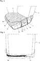
- the motor vehicle seat on which the protective cover is to be placed comprises a seat part 1 and a backrest part 2.
- the protective cover can be placed on the seat part 1.
- a separate protective cover can be placed on the backrest part 2.
- a protective cover according to the invention that can be placed against the seat part 1 could also be designed in one piece with a protective cover that can be placed against the backrest part 2.
- the protective cover has a cover material 3, which has a seat surface section 3a for resting on the seat surface of the seat part 1, a front section 3b for resting on the front narrow side of the seat part 1 and side sections 3c for resting on the two lateral narrow sides of the seat part 1.
- a cover material 3 which has a seat surface section 3a for resting on the seat surface of the seat part 1, a front section 3b for resting on the front narrow side of the seat part 1 and side sections 3c for resting on the two lateral narrow sides of the seat part 1.
- Fig. 1 only the side section 3c is visible, which rests against the narrow side of the seat part 1 on the vehicle edge.
- the lower edge 3d of the in Fig. 1 The visible side section 3c does not extend to the lower end of the narrow side of the seat part 1 but is designed to be shortened.
- a first tensioning strap 4a extends from the lower edge 3d of the cover material 3.
- the tension belt 4a runs along the narrow side of the seat part 1 to the rear of the motor vehicle seat. Subsequent to its starting point from the lower edge 3d of the cover material 3, the distance to the lower edge 3d increases increasingly.
- the tensioning strap 4a thus runs over the entire longitudinal extent of the side section 3c of the cover material 3 at a distance from the lower edge 3d of the cover material 3. Between the in the area The lower edge 3d of the cover material 3 lying on the side section 3c and an opening 5 is therefore located on the tensioning strap 4a.
- Connecting straps 6 and 7 run between the lower edge 3d of the cover material 3 located in the area of the side section 3c and the tensioning belt 4a. These thus cross the opening 5 and connect the lower edge 3d to the tensioning belt 4a.
- the connecting straps 6, 7 each form a loop through which the tensioning belt 4a runs.
- the tension belt 4a can be displaced in its longitudinal direction with respect to this loop.
- Functional elements 8 in particular operating elements for adjusting the motor vehicle seat, are arranged on the visible narrow side of the seat part 1. These are in the area of the opening 5, that is between the lower edge 3d and the tensioning belt 4a, and are therefore accessible to the user.
- a tensioning strap 4b (cf. Fig. 2 ) from the lower edge of the upholstery fabric.
- the design of the protective cover on this side could be the same as on the one in Fig. 1 visible side. Since, however, no functional elements are usually arranged on this side of the seat part, the side section of the cover material 3 on this side could also extend to the lower end of the narrow side of the seat part and the tensioning strap 4b could extend from the rear end of the side section of the cover material 3.
- a back tensioning strap 9 is arranged on the cover material in the area of the rear end of the side section 3c, which extends from the lower edge of the side section and runs obliquely downwards and backwards and in the rearmost area of the narrow side of the seat part or is connected to the tension belt 4a on the rear of the motor vehicle seat.
- the side section 3c is only very narrow in the area of the rear end of the seat surface section 3a. In contrast, the side section 3c could also extend a little further downwards. On the other hand, the side section 3c could also end in front of the rear end of the seat surface section 3a. This in Fig. 1 The rear connecting band 7 shown and the back tensioning band 9 could then extend from the edge of the seat surface section 3a.
- the tensioning belts 4a, 4b led to the rear of the motor vehicle seat can be connected to one another, cf. Fig. 2 .
- the connection is made via a buckle 10.
- the tensioning straps 4a, 4b are free sections of a band 4 which is sewn to the lower edge 3d of the cover material 3 in the area between the end sections forming the tensioning straps 4a, 4b.
- the cover material 3 can advantageously also have an insertion section adjoining the rear end of the seat surface section 3a, which is shown in FIG Fig. 1 is not visible and is inserted into the gap between the seat part 1 and the backrest part 2, as is known.
- the point at which the tensioning strap 4a starts from the lower edge 3d of the cover material 3 is in the embodiment in the transition area between the front section 3b and the side section 3c.
- this starting point could also be at a point in the area of the front half of the side section 3c. Subsequent to the starting point, the lower edge 3d would run back up towards the rear of the motor vehicle seat.
- connecting strap 6, 7 could run between the edge of the cover material 3 and the tensioning strap 4a running at a distance from it, or more than two such connecting straps could be provided.
- FIG. 3 A second embodiment of the invention is shown in Fig. 3 shown.
- the differences from the first exemplary embodiment are explained below. Otherwise, the description for the first exemplary embodiment can be used accordingly.
- a tunnel collar 12 is formed here on the lower edge 3d of the cover material 3, through which a band 4 runs.
- the sections protruding from the tunnel collar 12 form the tensioning belts 4a, 4b in a manner analogous to that described in the first exemplary embodiment.
- the starting point of the tensioning belt 4a from the lower edge of the cover material 3 is, as shown in FIG. 5, in the transition area between the front section 3b and the side section 3c, but could again also be in a front half of the side section 3c.
- the back tensioning strap is also omitted, but could also be present.
- Fig. 4 shows a possible modification of the mutual connection of the tensioning straps 4a, 4b by means of a Velcro fastener.
- the hook parts and fleece parts of the Velcro fastener are attached to one of the tensioning straps 4a, which is passed through an eyelet attached to the other of the tensioning straps 4b.
- one of the tensioning straps 4a could also have the hook part and the other of the tensioning straps 4b could have the fleece part of the Velcro fastener.
Landscapes
- Engineering & Computer Science (AREA)
- Aviation & Aerospace Engineering (AREA)
- Transportation (AREA)
- Mechanical Engineering (AREA)
- Seats For Vehicles (AREA)
- Motor Or Generator Frames (AREA)
Abstract
Description
- Die Erfindung bezieht sich auf einen Schonbezug für ein Sitzteil eines Kraftfahrzeugsitzes mit einem Bezugsstoff zum Überdecken einer Sitzfläche des Sitzteils und Spannriemen zum Befestigen des Schonbezuges am Kraftfahrzeugsitz.
- Bei Schonbezügen für Sitzteile von Kraftfahrzeugen besteht ein Problem darin, dass seitlich an den Sitzteilen Bedienelemente angeordnet sind, welche auch nach Anbringung des Schonbezuges möglichst zugänglich bleiben sollen. Da diese Bedienelemente je nach Fahrzeug sehr unterschiedlich angeordnet und ausgebildet sind, werden Schonbezüge häufig genau an die jeweilige Fahrzeugtype angepasst, was den Herstellungs- und Lagerungsaufwand wesentlich erhöht. Andere, universell einsetzbare Schonbezüge erstrecken sich auch über die Schmalseiten des Sitzteils, wobei in Kauf genommen wird, dass Funktionselemente an der Schmalseite des Sitzteils überdeckt werden.
- Aufgabe der Erfindung ist es, einen Schonbezug der eingangs genannten Art bereitzustellen, der sich in vorteilhafter Weise zum Einsatz bei verschiedenartigen Sitzteilen mit unterschiedlich angeordneten Bedienelementen an der Schmalseite eignet. Erfindungsgemäß gelingt dies durch einen Schonbezug mit den Merkmalen des Anspruchs 1.
- Der Schonbezug gemäß der Erfindung weist zumindest eine Öffnung für an einer der seitlichen Schmalseiten des Sitzteils angeordnete Funktionselemente, insbesondere Bedienelemente, des Sitzteils auf, wobei die Öffnung zwischen einem Rand des Bezugsstoffs und einem, vorzugsweise gummielastisch dehnbar ausgebildeten, Spannriemen liegt. Dieser Spannriemen verläuft bezogen auf den Gebrauchszustand des Schonbezuges im Abstand unterhalb des Randes des Bezugsstoffs zur Rückseite des Kraftfahrzeugsitzes und kann dort vorteilhafterweise mit einem weiteren, auf der gegenüberliegenden Seite des Bezugsstoffs vom Bezugsstoff ausgehenden, zur Rückseite des Kraftfahrzeugsitzes verlaufenden, vorzugsweise gummielastisch dehnbar ausgebildeten, Spannriemen verbunden werden.
- Günstigerweise weist der Bezugsstoff einen Sitzflächenabschnitt zur Auflage auf der Sitzfläche des Sitzteils, einen Vorderabschnitt zur Anlage an der vorderen Schmalseite des Sitzteils und Seitenabschnitte zur Anlage an den seitlichen Schmalseiten des Sitzteils auf, wobei der Spannriemen im Abstand unterhalb des unteren Randes eines der Seitenabschnitte des Bezugsstoffs zur Rückseite des Kraftfahrzeugsitzes verläuft. Dieser Seitenabschnitt ist also zumindest bereichsweise verkürzt ausgebildet, sodass der untere Rand des Seitenabschnitts oberhalb von an der Schmalseite des Sitzteils angeordneten Funktionselementen, insbesondere Bedienelementen, zum Liegen kommt, wobei der Spannriemen unterhalb dieser Funktionselemente verlaufen kann. Funktionselemente an der Schmalseite des Sitzteils können somit im Bereich der Öffnung liegen, die zwischen dem unteren Rand des Seitenabschnitts des Schonbezugs und dem Spannriemen liegt.
- Durch die Erfindung kann ein für unterschiedliche Anordnungen von Funktionselementen an der Schmalseite des Sitzteils sich eignender Schonbezug bereitgestellt werden, der dennoch in stabiler Weise am Kraftfahrzeugsitz befestigbar ist.
- Vorteilhafterweise verläuft zwischen dem unteren Rand des Seitenabschnitts und dem im Abstand von diesem verlaufenden Spannriemen mindestens ein Verbindungsband. Die Stabilität der Befestigung des Schonbezuges am Sitzteil wird dadurch weiter verbessert. Das Verbindungsband weist günstigerweise eine Schlaufe auf, durch welche der Spannriemen verläuft, wobei die Schlaufe gegenüber dem Spannriemen in dessen Längsrichtung verschiebbar ist.
- Das mindestens eine Verbindungsband ist vorzugsweise gummielastisch dehnbar ausgebildet.
- Der Punkt, an welchem der mindestens eine im Abstand unterhalb des Randes des Bezugsstoffs zur Rückseite des Kraftfahrzeugsitzes verlaufenden Spannriemens vom Bezugsstoff ausgeht, liegt vorteilhafterweise im Bereich der vorderen Hälfte des Seitenabschnitts oder im Bereich des Übergangs zwischen dem Vorderabschnitt und dem Seitenabschnitt des Bezugsstoffs. Der Ausgangspunkt des Spannriemens befindet sich hierbei am unteren Rand des Bezugsstoffs. Wenn man bezogen auf den Gebrauchszustand den Verlauf dieses unteren Randes des Bezugsstoffs zum hinteren Ende des Bezugsstoffs betrachtet, so verläuft der untere Rand des Bezugsstoffs anschließend an den Ausgangspunkt des Spannriemens nach oben, um die Öffnung zwischen dem unteren Rand des Bezugsstoffs und dem Spannriemen auszubilden.
- Die beiden auf gegenüberliegenden Seiten des Bezugsstoffs ausgehenden, zur Rückseite des Kraftfahrzeugsitzes verlaufenden Spannriemen sind an der Rückseite des Kraftfahrzeugsitzes insbesondere mittels eines Klettverschlusses oder mittels einer Schnalle miteinander verbindbar.
- Zur weitere Verbesserung der Befestigung des Schonbezuges am Sitzteil ist vorteilhafterweise vorgesehen, dass vom Rand des Bezugsstoffs, unterhalb von dem der Spannriemen verläuft, im Bereich des hinteren Endes der Sitzfläche des Sitzteils, also im Bereich des hinteren Endes des Sitzflächenabschnitts des Bezugsstoffs, ein Rückspannband ausgeht, welches schräg nach hinten und unten verläuft und mit dem Spannriemen verbunden ist.
- Wenn in dieser Schrift von "vorne" und "hinten" die Rede ist, so ist dies auf die Fahrtrichtung des Kraftfahrzeugs bezogen.
- Weitere Vorteile und Einzelheiten der Erfindung werden im Folgenden anhand der beiliegenden Zeichnung erläutert. In dieser zeigen:
-
Fig. 1 eine Schrägsicht eines Teils eines Kraftfahrzeugsitzes mit einem angelegten Schonbezug gemäß einem ersten Ausführungsbeispiel der Erfindung; -
Fig. 2 den Kraftfahrzeugsitz mit dem angelegten Schonbezug von der Rückseite; -
Fig. 3 eine Darstellungen entsprechendFig. 1 für ein zweites Ausführungsbeispiel der Erfindung; -
Fig. 4 eine alternative Verbindung der Spannriemen an der Rückseite des Kraftfahrzeugsitzes. - Der Kraftfahrzeugsitz, an welchen der Schonbezug anzulegen ist, umfasst ein Sitzteil 1 und ein Rückenlehnenteil 2. Der Schonbezug ist an das Sitzteil 1 anlegbar. An das Rückenlehnenteil 2 kann ein separater Schonbezug angelegt werden. Ein erfindungsgemäßer, an das Sitzteil 1 anlegbarer Schonbezug könnte auch einteilig mit einem an das Rückenlehnenteil 2 anlegbaren Schonbezug ausgebildet sein.
- Der Schonbezug weist einen Bezugsstoff 3 auf, der einen Sitzflächenabschnitt 3a zur Auflage auf der Sitzfläche des Sitzteils 1, ein Vorderabschnitt 3b zur Anlage an der vorderen Schmalseite des Sitzteils 1 und Seitenabschnitte 3c zur Anlage an den beiden seitlichen Schmalseiten des Sitzteils 1aufweist. In
Fig. 1 ist nur der Seitenabschnitt 3c sichtbar, welcher an der fahrzeugrandseitigen Schmalseite des Sitzteils 1 anliegt. - Der untere Rand 3d des in
Fig. 1 sichtbaren Seitenabschnitts 3c erstreckt sich nicht bis zum unteren Ende der Schmalseite des Sitzteils 1 sondern ist verkürzt ausgebildet. - Im Übergangsbereich zwischen dem Vorderabschnitt 3b und dem Seitenabschnitt 3c geht vom unteren Rand 3d des Bezugsstoffs 3 ein erster Spannriemen 4a aus. Der Spannriemen 4a verläuft entlang der Schmalseite des Sitzteils 1 nach hinten zur Rückseite des Kraftfahrzeugsitzes. Anschließend an seinen Ausgangspunkt vom unteren Rand 3d des Bezugsstoffs 3 vergrößert sich hierbei der Abstand zum unteren Rand 3d zunehmend. Im Ausführungsbeispiel verläuft der Spannriemen 4a somit über die gesamte Längserstreckung des Seitenabschnitts 3c des Bezugsstoffs 3 im Abstand vom unteren Rand 3d des Bezugsstoffs 3. Zwischen dem im Bereich des Seitenabschnitts 3c liegenden unteren Rand 3d des Bezugsstoffs 3 und dem Spannriemen 4a liegt somit eine Öffnung 5.
- Zwischen dem im Bereich des Seitenabschnitts 3c liegenden unteren Rand 3d des Bezugsstoffs 3 und dem Spannriemen 4a verlaufen Verbindungsbänder 6 und 7. Diese überqueren somit die Öffnung 5 und verbinden den unteren Rand 3d mit dem Spannriemen 4a. Die Verbindungsbänder 6, 7 bilden jeweils eine Schlaufe aus, durch welche der Spannriemen 4a verläuft. Der Spannriemen 4a ist hierbei in seine Längsrichtung gegenüber dieser Schlaufe verschiebbar.
- An der in
Fig. 1 sichtbaren seitlichen Schmalseite des Sitzteils 1 sind Funktionselemente 8, insbesondere Bedienelemente zur Verstellung des Kraftfahrzeugsitzes, angeordnet. Diese liegen im Bereich der Öffnung 5, also zwischen dem unteren Rand 3d und dem Spannriemen 4a, und sind somit für den Benutzer zugänglich. - Auf der in
Fig. 1 nicht sichtbaren, gegenüberliegenden Seite des Bezugsstoffs bzw. Kraffahrzeugsitzes geht ebenfalls ein Spannriemen 4b (vgl.Fig. 2 ) vom unteren Rand des Bezugsstoffs aus. Grundsätzlich könnte die Ausbildung des Schonbezuges auf dieser Seite gleich wie auf der inFig. 1 sichtbaren Seite sein. Da auf dieser Seite des Sitzteils üblicherweise aber keine Funktionselemente angeordnet sind, könnte der auf dieser Seite liegende Seitenabschnitt des Bezugsstoffs 3 auch bis zum unteren Ende der Schmalseite des Sitzteils verlaufen und der Spannriemen 4b könnte vom hinteren Ende des Seitenabschnitts des Bezugsstoffs 3 ausgehen. - Zur Verbesserung der Halterung des Bezugsstoffs 3 in seinem hinteren Bereich ist am Bezugsstoff im Bereich des hinteren Endes des Seitenabschnitts 3c ein vom unteren Rand des Seitenabschnitts ausgehendes Rückspannband 9 angeordnet, welches schräg nach unten und hinten verläuft und im hintersten Bereich der seitlichen Schmalseite des Sitzteils oder an der Rückseite des Kraftfahrzeugsitzes mit dem Spannriemen 4a verbunden ist.
- Im in
Fig. 1 dargestellten Ausführungsbeispiel ist der Seitenabschnitt 3c im Bereich des hinteren Endes des Sitzflächenabschnitts 3a nur mehr sehr schmal ausgebildet. Der Seitenabschnitt 3c könnte demgegenüber auch etwas weiter nach unten reichen. Andererseits könnte der Seitenabschnitt 3c auch vor dem hinteren Ende des Sitzflächenabschnitts 3a enden. Das inFig. 1 dargestellte hintere Verbindungsband 7 und das Rückspannband 9 könnten dann vom Rand des Sitzflächenabschnitts 3a ausgehen. - Die zur Rückseite des Kraftfahrzeugsitzes geführten Spannriemen 4a, 4b können miteinander verbunden werden, vgl.
Fig. 2 . In diesem Ausführungsbeispiel erfolgt die Verbindung über eine Schnalle 10. - Im Ausführungsbeispiel sind die Spannriemen 4a, 4b freie Abschnitte eines Bandes 4, welches im Bereich zwischen den die Spannriemen 4a, 4b bildenden Endabschnitten an den unteren Rand 3d des Bezugsstoffs 3 angenäht ist.
- Der Bezugsstoff 3 kann günstigerweise noch einen an das hintere Ende des Sitzflächenabschnitts 3a anschließenden Einsteckabschnitt aufweisen, welcher in
Fig. 1 nicht sichtbar ist und in den Spalt zwischen dem Sitzteil 1 und dem Rückenlehnenteil 2 eingesteckt ist, wie dies bekannt ist. - Wie zuvor beschrieben, liegt der Punkt, an welchem der Spannriemen 4a vom unteren Rand 3d des Bezugsstoffs 3 ausgeht, im Ausführungsbeispiel im Übergangsbereich zwischen dem Vorderabschnitt 3b und dem Seitenabschnitt 3c. Dieser Ausgangspunkt könnte in einer modifizierten Ausführungsform auch an einer Stelle im Bereich der vorderen Hälfte des Seitenabschnitts 3c liegen. Anschließend an den Ausgangspunkt würde der untere Rand 3d zur Rückseite des Kraftfahrzeugsitzes hin wieder nach oben verlaufen.
- Zwischen dem Rand des Bezugsstoffs 3 und dem im Abstand hierzu verlaufenden Spannriemen 4a könnte beispielsweise auch nur ein Verbindungsband 6, 7 verlaufen oder mehr als zwei solche Verbindungsbänder könnten vorgesehen sein.
- Ein zweites Ausführungsbeispiel der Erfindung ist in
Fig. 3 dargestellt. Im Folgenden werden die Unterschiede gegenüber dem ersten Ausführungsbeispiel erläutert. Im Übrigen ist die Beschreibung zum ersten Ausführungsbeispiel entsprechend heranziehbar. - Im Unterschied zum ersten Ausführungsbeispiel ist hier am unteren Rand 3d des Bezugsstoffs 3 ein Tunnelbund 12 ausgebildet, durch welchen ein Band 4 verläuft. Die aus dem Tunnelbund 12 herausstehenden Abschnitte bilden in analoger Weise wie beim ersten Ausführungsbeispiel beschrieben die Spannriemen 4a, 4b. Der Ausgangspunkt des Spannriemens 4a vom unteren Rand des Bezugsstoffs 3 liegt entsprechend Fig. 5 im Übergangsbereich zwischen dem Vorderabschnitt 3b und dem Seitenabschnitt 3c, könnte aber wiederum ebenso in einer vorderen Hälfte des Seitenabschnitts 3c liegen.
- Außerdem entfallen im in
Fig. 3 gezeigten Ausführungsbeispiel die Schnallen 11 der Verbindungsbänder. Die Schlaufen der Verbindungsbänder 6, 7 sind durch eine Vernähung ausgebildet. Die Ausbildung könnte aber auch entsprechend dem ersten Ausführungsbeispiel sein. - Auch das Rückspannband ist weggelassen, könnte aber auch vorhanden sein.
-
Fig. 4 zeigt im weiteren eine mögliche Modifikation der gegenseitigen Verbindung der Spannriemen 4a, 4b mittels eines Klettverschlusses. Die Hakenteile und Vliesteile des Klettverschlusses sind hierbei an einem der Spannriemen 4a angebracht, welcher durch eine am anderen der Spannriemen 4b angebrachte Öse durchgeführt wird. Stattdessen könnte auch einer der Spannriemen 4a das Hakenteil und der andere der Spannriemen 4b das Vliesteil des Klettverschlusses aufweisen. -
- 1
- Sitzteil
- 2
- Rückenlehnenteil
- 3
- Bezugsstoff
- 3a
- Sitzflächenabschnitt
- 3b
- Vorderabschnitt
- 3c
- Seitenabschnitt
- 3d
- unterer Rand
- 4
- Band
- 4a
- Spannriemen
- 4b
- Spannriemen
- 5
- Öffnung
- 6
- Verbindungsband
- 7
- Verbindungsband
- 8
- Funktionselement
- 9
- Rückspannband
- 10
- Schnalle
- 11
- Schnalle
- 12
- Tunnelbund
Claims (10)
- Schonbezug für ein Sitzteil (1) eines Kraftfahrzeugsitzes mit einem Bezugsstoff (3) zum Überdecken einer Sitzfläche des Sitzteils (1) und Spannriemen (4a, 4b) zum Befestigen des Schonbezuges am Kraftfahrzeugsitz, dadurch gekennzeichnet, dass der Schonbezug zumindest eine Öffnung (5) für an einer der seitlichen Schmalseiten des Sitzteils (1) angeordnete Funktionselemente (8) des Sitzteils (1) aufweist, wobei die Öffnung (5) zwischen einem Rand (3d) des Bezugsstoffs (3) und einem, vorzugsweise gummielastisch dehnbar ausgebildeten, Spannriemen (4a) liegt, welcher im Abstand unterhalb des Randes (3d) des Bezugsstoffs (3) zur Rückseite des Kraftfahrzeugsitzes verläuft.
- Schonbezug nach Anspruch 1, dadurch gekennzeichnet, dass der Bezugsstoff (3) einen Sitzflächenabschnitt (3a) zur Auflage auf der Sitzfläche des Sitzteils (1), einen Vorderabschnitt (3b) zur Anlage an der vorderen Schmalseite des Sitzteils (1) und Seitenabschnitte (3c) zur Anlage an den seitlichen Schmalseiten des Sitzteils umfasst, wobei der Spannriemen (4a) im Abstand unterhalb des unteren Randes (3d) eines der Seitenabschnitte (3c) des Bezugsstoffs (3) zur Rückseite des Kraftfahrzeugsitzes verläuft.
- Schonbezug nach Anspruch 1 oder 2, dadurch gekennzeichnet, dass der Spannriemen (4a) im Bereich eines unteren Randes (3d) des Bezugsstoffs (3) vom Bezugsstoff (3) ausgeht und auf der Rückseite des Kraftfahrzeugsitzes mit einem weiteren, auf der gegenüberliegenden Seite des Bezugsstoffs (3) im Bereich eines unteren Randes (3d) des Bezugsstoffs (3) vom Bezugsstoff (3) ausgehenden, zur Rückseite des Kraftfahrzeugsitzes verlaufenden, vorzugsweise gummielastisch dehnbar ausgebildeten, Spannriemen (4b) verbindbar ist.
- Schonbezug nach einem der Ansprüche 1 bis 3, dadurch gekennzeichnet, dass zwischen dem Rand des Bezugsstoffs (3) und dem Spannriemen (4a), welcher im Abstand unterhalb des Randes (3d) des Bezugsstoffs (3d) verläuft, mindestens ein, vorzugsweise gummielastisch dehnbar ausgebildetes, Verbindungsband (6, 7) verläuft.
- Schonbezug nach Anspruch 4, dadurch gekennzeichnet, dass das Verbindungsband (6, 7) eine Schlaufe ausbildet, durch welche der Spannriemen (4a) verläuft, wobei die Schlaufe gegenüber dem Spannriemen (4a) in dessen Längsrichtung verschiebbar ist.
- Schonbezug nach einem der Ansprüche 1 bis 5, dadurch gekennzeichnet, dass der mindestens eine, im Abstand unterhalb des Randes (3d) des Bezugsstoffs (3) verlaufende Spannriemen (4a) im Bereich der vorderen Hälfte des Seitenabschnitts (3c) oder im Bereich des Übergangs zwischen dem Vorderabschnitt (3b) und dem Seitenabschnitt (3c) des Bezugsstoffs (3) vom unteren Rand (3d) des Bezugsstoffs (3) ausgeht.
- Schonbezug nach einem der Ansprüche 1 bis 6, dadurch gekennzeichnet, dass die auf gegenüberliegenden Seiten des Bezugsstoffs (3) vom Bezugsstoff (3) ausgehenden, zur Rückseite des Kraftfahrzeugsitzes verlaufenden Spannriemen (4a, 4b) mittels eines Klettverschlusses oder mittels einer Schnalle (10) miteinander verbindbar sind.
- Schonbezug nach einem der Ansprüche 1 bis 7, dadurch gekennzeichnet, dass die auf gegenüberliegenden Seiten des Bezugsstoffs (3) vom Bezugsstoff (3) ausgehenden, zur Rückseite des Kraftfahrzeugsitzes verlaufenden Spannriemen (4a, 4b) vom Bezugsstoff (3) abstehende Abschnitte eines im Bereich zwischen diesen Abschnitten an den unteren Rand (3d) des Bezugsstoffs (3) angenähten Bandes sind.
- Schonbezug nach einem der Ansprüche 1 bis 7, dadurch gekennzeichnet, dass am unteren Rand (3d) des Bezugsstoffs (3) ein Tunnelbund (12) ausgebildet ist, durch welchen ein Band (4) verläuft, wobei die auf gegenüberliegenden Seiten des Bezugsstoffs (3) vom Bezugsstoff (3) ausgehenden, zur Rückseite des Kraftfahrzeugsitzes verlaufenden Spannriemen (4a, 4b) von aus dem Tunnelbund (12) herausragenden Abschnitten dieses Bandes (4) gebildet werden.
- Schonbezug nach einem der Ansprüche 1 bis 9, dadurch gekennzeichnet, dass vom Rand des Bezugsstoffs (3), unterhalb von dem der Spannriemen (4a) verläuft, im Bereich des hinteren Endes der Sitzfläche des Sitzteils ein Rückspannband (9) ausgeht, welches schräg nach hinten und unten verläuft und mit dem Spannriemen (4a) verbunden ist.
Applications Claiming Priority (1)
| Application Number | Priority Date | Filing Date | Title |
|---|---|---|---|
| ATA192/2019A AT521957B1 (de) | 2019-05-22 | 2019-05-22 | Schonbezug für ein Sitzteil eines Kraftfahrzeugsitzes |
Publications (2)
| Publication Number | Publication Date |
|---|---|
| EP3750744A1 true EP3750744A1 (de) | 2020-12-16 |
| EP3750744B1 EP3750744B1 (de) | 2023-05-10 |
Family
ID=70049930
Family Applications (1)
| Application Number | Title | Priority Date | Filing Date |
|---|---|---|---|
| EP20165978.6A Active EP3750744B1 (de) | 2019-05-22 | 2020-03-26 | Schonbezug für ein sitzteil eines kraftfahrzeugsitzes |
Country Status (6)
| Country | Link |
|---|---|
| EP (1) | EP3750744B1 (de) |
| AT (1) | AT521957B1 (de) |
| DK (1) | DK3750744T3 (de) |
| ES (1) | ES2951357T3 (de) |
| HU (1) | HUE062556T2 (de) |
| PL (1) | PL3750744T3 (de) |
Families Citing this family (1)
| Publication number | Priority date | Publication date | Assignee | Title |
|---|---|---|---|---|
| DE102018202390A1 (de) * | 2018-02-16 | 2019-08-22 | Bayerische Motoren Werke Aktiengesellschaft | Kraftfahrzeugsitz, hiermit ausgestattetes Kraftfahrzeug sowie Verfahren zum Einstellen einer Bezugsspannung des Kraftfahrzeugsitzes |
Citations (3)
| Publication number | Priority date | Publication date | Assignee | Title |
|---|---|---|---|---|
| US4396227A (en) * | 1979-06-28 | 1983-08-02 | Neilson William W | Car seat covers |
| US9327629B2 (en) * | 2014-09-04 | 2016-05-03 | Ford Global Technologies, Llc | Temporary seat covers |
| US9403462B2 (en) * | 2001-10-09 | 2016-08-02 | Shawn D. Spitzer | Uniform seat cover and seat fashioned with same |
Family Cites Families (2)
| Publication number | Priority date | Publication date | Assignee | Title |
|---|---|---|---|---|
| DE1833522U (de) * | 1960-10-27 | 1961-06-22 | Georg Schwahn | Schonbezug fuer autositz. |
| DE1836928U (de) * | 1961-06-15 | 1961-08-31 | B Medrisch | Autositz-schonbezug. |
-
2019
- 2019-05-22 AT ATA192/2019A patent/AT521957B1/de active
-
2020
- 2020-03-26 ES ES20165978T patent/ES2951357T3/es active Active
- 2020-03-26 PL PL20165978.6T patent/PL3750744T3/pl unknown
- 2020-03-26 HU HUE20165978A patent/HUE062556T2/hu unknown
- 2020-03-26 EP EP20165978.6A patent/EP3750744B1/de active Active
- 2020-03-26 DK DK20165978.6T patent/DK3750744T3/da active
Patent Citations (3)
| Publication number | Priority date | Publication date | Assignee | Title |
|---|---|---|---|---|
| US4396227A (en) * | 1979-06-28 | 1983-08-02 | Neilson William W | Car seat covers |
| US9403462B2 (en) * | 2001-10-09 | 2016-08-02 | Shawn D. Spitzer | Uniform seat cover and seat fashioned with same |
| US9327629B2 (en) * | 2014-09-04 | 2016-05-03 | Ford Global Technologies, Llc | Temporary seat covers |
Also Published As
| Publication number | Publication date |
|---|---|
| HUE062556T2 (hu) | 2023-11-28 |
| AT521957B1 (de) | 2020-07-15 |
| DK3750744T3 (da) | 2023-07-31 |
| EP3750744B1 (de) | 2023-05-10 |
| ES2951357T3 (es) | 2023-10-19 |
| PL3750744T3 (pl) | 2023-09-11 |
| AT521957A4 (de) | 2020-07-15 |
Similar Documents
| Publication | Publication Date | Title |
|---|---|---|
| DE3109792A1 (de) | Schliesse oder schnalle, insbesondere fuer uhrarmbaender | |
| EP3328232A1 (de) | Gepäckstück mit stoppereinrichtung | |
| DE6606815U (de) | Automatisch sperrender schieber fuer reissverschluesse. | |
| DE2748043A1 (de) | Selbstsperrender schieber fuer reissverschluesse | |
| DE3208807A1 (de) | Skischuh | |
| EP3750744B1 (de) | Schonbezug für ein sitzteil eines kraftfahrzeugsitzes | |
| DE2458636B2 (de) | Selbsttätig sperrender Schieber für einen verdeckten Reißverschluß | |
| DE1278775B (de) | Trennbares, aus spritzbarem Kunststoff bestehendes Endglied fuer einen Reissverschluss | |
| DE1276388B (de) | Trennbares Endglied fuer einen Reissverschluss | |
| EP2775873B1 (de) | Beinkleid mit schiebeverschluss | |
| DE2304540C3 (de) | Verschluß für ein auf Zug beanspruchtes Band | |
| CH214449A (de) | Verschluss an Riemen von Armbanduhren. | |
| DE1557429B2 (de) | Verschlusschnalle fuer sicherheitsgurte | |
| DE202019005372U1 (de) | Schonbezug für die Rücksitzbank eines Kraftfahrzeugs | |
| DE3428858C2 (de) | ||
| DE9111299U1 (de) | Schnellversteller für ein Gurtband-Rückhaltesystem | |
| EP0236664B1 (de) | Spannband, insbesondere zum Binden von Kabelbäumen | |
| DE928800C (de) | Schnallenverschluss, insbesondere fuer Schuhe | |
| DE289901C (de) | ||
| DE454352C (de) | Durchzugband fuer Bekleidungsstuecke, insbesondere Schlupfhosen | |
| DE1610471B1 (de) | Reissverschlussschieber | |
| DE102015216556B4 (de) | Schließanordnung für einen Gurt | |
| DE2522403A1 (de) | Uhrarmband aus leder o.dgl. | |
| DE7422182U (de) | Kopf- und nackenstuetze fuer kraftfahrzeugsitze | |
| DE1610471C (de) | Reißverschlußschieber |
Legal Events
| Date | Code | Title | Description |
|---|---|---|---|
| PUAI | Public reference made under article 153(3) epc to a published international application that has entered the european phase |
Free format text: ORIGINAL CODE: 0009012 |
|
| STAA | Information on the status of an ep patent application or granted ep patent |
Free format text: STATUS: THE APPLICATION HAS BEEN PUBLISHED |
|
| AK | Designated contracting states |
Kind code of ref document: A1 Designated state(s): AL AT BE BG CH CY CZ DE DK EE ES FI FR GB GR HR HU IE IS IT LI LT LU LV MC MK MT NL NO PL PT RO RS SE SI SK SM TR |
|
| AX | Request for extension of the european patent |
Extension state: BA ME |
|
| STAA | Information on the status of an ep patent application or granted ep patent |
Free format text: STATUS: REQUEST FOR EXAMINATION WAS MADE |
|
| 17P | Request for examination filed |
Effective date: 20210519 |
|
| RBV | Designated contracting states (corrected) |
Designated state(s): AL AT BE BG CH CY CZ DE DK EE ES FI FR GB GR HR HU IE IS IT LI LT LU LV MC MK MT NL NO PL PT RO RS SE SI SK SM TR |
|
| RIC1 | Information provided on ipc code assigned before grant |
Ipc: B60N 2/60 20060101AFI20221122BHEP |
|
| GRAP | Despatch of communication of intention to grant a patent |
Free format text: ORIGINAL CODE: EPIDOSNIGR1 |
|
| STAA | Information on the status of an ep patent application or granted ep patent |
Free format text: STATUS: GRANT OF PATENT IS INTENDED |
|
| INTG | Intention to grant announced |
Effective date: 20230109 |
|
| GRAJ | Information related to disapproval of communication of intention to grant by the applicant or resumption of examination proceedings by the epo deleted |
Free format text: ORIGINAL CODE: EPIDOSDIGR1 |
|
| GRAP | Despatch of communication of intention to grant a patent |
Free format text: ORIGINAL CODE: EPIDOSNIGR1 |
|
| GRAS | Grant fee paid |
Free format text: ORIGINAL CODE: EPIDOSNIGR3 |
|
| GRAA | (expected) grant |
Free format text: ORIGINAL CODE: 0009210 |
|
| STAA | Information on the status of an ep patent application or granted ep patent |
Free format text: STATUS: THE PATENT HAS BEEN GRANTED |
|
| INTG | Intention to grant announced |
Effective date: 20230314 |
|
| AK | Designated contracting states |
Kind code of ref document: B1 Designated state(s): AL AT BE BG CH CY CZ DE DK EE ES FI FR GB GR HR HU IE IS IT LI LT LU LV MC MK MT NL NO PL PT RO RS SE SI SK SM TR |
|
| REG | Reference to a national code |
Ref country code: GB Ref legal event code: FG4D Free format text: NOT ENGLISH |
|
| REG | Reference to a national code |
Ref country code: AT Ref legal event code: REF Ref document number: 1566389 Country of ref document: AT Kind code of ref document: T Effective date: 20230515 Ref country code: CH Ref legal event code: EP |
|
| REG | Reference to a national code |
Ref country code: DE Ref legal event code: R096 Ref document number: 502020003217 Country of ref document: DE |
|
| REG | Reference to a national code |
Ref country code: IE Ref legal event code: FG4D Free format text: LANGUAGE OF EP DOCUMENT: GERMAN |
|
| REG | Reference to a national code |
Ref country code: DK Ref legal event code: T3 Effective date: 20230724 |
|
| REG | Reference to a national code |
Ref country code: SE Ref legal event code: TRGR |
|
| REG | Reference to a national code |
Ref country code: NL Ref legal event code: FP |
|
| REG | Reference to a national code |
Ref country code: LT Ref legal event code: MG9D |
|
| REG | Reference to a national code |
Ref country code: ES Ref legal event code: FG2A Ref document number: 2951357 Country of ref document: ES Kind code of ref document: T3 Effective date: 20231019 |
|
| PG25 | Lapsed in a contracting state [announced via postgrant information from national office to epo] |
Ref country code: PT Free format text: LAPSE BECAUSE OF FAILURE TO SUBMIT A TRANSLATION OF THE DESCRIPTION OR TO PAY THE FEE WITHIN THE PRESCRIBED TIME-LIMIT Effective date: 20230911 Ref country code: NO Free format text: LAPSE BECAUSE OF FAILURE TO SUBMIT A TRANSLATION OF THE DESCRIPTION OR TO PAY THE FEE WITHIN THE PRESCRIBED TIME-LIMIT Effective date: 20230810 |
|
| REG | Reference to a national code |
Ref country code: HU Ref legal event code: AG4A Ref document number: E062556 Country of ref document: HU |
|
| PG25 | Lapsed in a contracting state [announced via postgrant information from national office to epo] |
Ref country code: RS Free format text: LAPSE BECAUSE OF FAILURE TO SUBMIT A TRANSLATION OF THE DESCRIPTION OR TO PAY THE FEE WITHIN THE PRESCRIBED TIME-LIMIT Effective date: 20230510 Ref country code: LV Free format text: LAPSE BECAUSE OF FAILURE TO SUBMIT A TRANSLATION OF THE DESCRIPTION OR TO PAY THE FEE WITHIN THE PRESCRIBED TIME-LIMIT Effective date: 20230510 Ref country code: LT Free format text: LAPSE BECAUSE OF FAILURE TO SUBMIT A TRANSLATION OF THE DESCRIPTION OR TO PAY THE FEE WITHIN THE PRESCRIBED TIME-LIMIT Effective date: 20230510 Ref country code: IS Free format text: LAPSE BECAUSE OF FAILURE TO SUBMIT A TRANSLATION OF THE DESCRIPTION OR TO PAY THE FEE WITHIN THE PRESCRIBED TIME-LIMIT Effective date: 20230910 Ref country code: HR Free format text: LAPSE BECAUSE OF FAILURE TO SUBMIT A TRANSLATION OF THE DESCRIPTION OR TO PAY THE FEE WITHIN THE PRESCRIBED TIME-LIMIT Effective date: 20230510 Ref country code: GR Free format text: LAPSE BECAUSE OF FAILURE TO SUBMIT A TRANSLATION OF THE DESCRIPTION OR TO PAY THE FEE WITHIN THE PRESCRIBED TIME-LIMIT Effective date: 20230811 |
|
| PG25 | Lapsed in a contracting state [announced via postgrant information from national office to epo] |
Ref country code: FI Free format text: LAPSE BECAUSE OF FAILURE TO SUBMIT A TRANSLATION OF THE DESCRIPTION OR TO PAY THE FEE WITHIN THE PRESCRIBED TIME-LIMIT Effective date: 20230510 |
|
| PG25 | Lapsed in a contracting state [announced via postgrant information from national office to epo] |
Ref country code: SK Free format text: LAPSE BECAUSE OF FAILURE TO SUBMIT A TRANSLATION OF THE DESCRIPTION OR TO PAY THE FEE WITHIN THE PRESCRIBED TIME-LIMIT Effective date: 20230510 |
|
| PG25 | Lapsed in a contracting state [announced via postgrant information from national office to epo] |
Ref country code: SM Free format text: LAPSE BECAUSE OF FAILURE TO SUBMIT A TRANSLATION OF THE DESCRIPTION OR TO PAY THE FEE WITHIN THE PRESCRIBED TIME-LIMIT Effective date: 20230510 Ref country code: SK Free format text: LAPSE BECAUSE OF FAILURE TO SUBMIT A TRANSLATION OF THE DESCRIPTION OR TO PAY THE FEE WITHIN THE PRESCRIBED TIME-LIMIT Effective date: 20230510 Ref country code: RO Free format text: LAPSE BECAUSE OF FAILURE TO SUBMIT A TRANSLATION OF THE DESCRIPTION OR TO PAY THE FEE WITHIN THE PRESCRIBED TIME-LIMIT Effective date: 20230510 Ref country code: EE Free format text: LAPSE BECAUSE OF FAILURE TO SUBMIT A TRANSLATION OF THE DESCRIPTION OR TO PAY THE FEE WITHIN THE PRESCRIBED TIME-LIMIT Effective date: 20230510 |
|
| REG | Reference to a national code |
Ref country code: DE Ref legal event code: R097 Ref document number: 502020003217 Country of ref document: DE |
|
| PLBE | No opposition filed within time limit |
Free format text: ORIGINAL CODE: 0009261 |
|
| STAA | Information on the status of an ep patent application or granted ep patent |
Free format text: STATUS: NO OPPOSITION FILED WITHIN TIME LIMIT |
|
| PGFP | Annual fee paid to national office [announced via postgrant information from national office to epo] |
Ref country code: NL Payment date: 20240326 Year of fee payment: 5 |
|
| 26N | No opposition filed |
Effective date: 20240213 |
|
| PG25 | Lapsed in a contracting state [announced via postgrant information from national office to epo] |
Ref country code: SI Free format text: LAPSE BECAUSE OF FAILURE TO SUBMIT A TRANSLATION OF THE DESCRIPTION OR TO PAY THE FEE WITHIN THE PRESCRIBED TIME-LIMIT Effective date: 20230510 |
|
| PG25 | Lapsed in a contracting state [announced via postgrant information from national office to epo] |
Ref country code: SI Free format text: LAPSE BECAUSE OF FAILURE TO SUBMIT A TRANSLATION OF THE DESCRIPTION OR TO PAY THE FEE WITHIN THE PRESCRIBED TIME-LIMIT Effective date: 20230510 |
|
| PGFP | Annual fee paid to national office [announced via postgrant information from national office to epo] |
Ref country code: IT Payment date: 20240321 Year of fee payment: 5 Ref country code: BE Payment date: 20240326 Year of fee payment: 5 |
|
| PGFP | Annual fee paid to national office [announced via postgrant information from national office to epo] |
Ref country code: CH Payment date: 20240401 Year of fee payment: 5 |
|
| PG25 | Lapsed in a contracting state [announced via postgrant information from national office to epo] |
Ref country code: CZ Free format text: LAPSE BECAUSE OF NON-PAYMENT OF DUE FEES Effective date: 20240326 |
|
| REG | Reference to a national code |
Ref country code: DK Ref legal event code: EBP Effective date: 20240331 |
|
| REG | Reference to a national code |
Ref country code: SE Ref legal event code: EUG |
|
| PG25 | Lapsed in a contracting state [announced via postgrant information from national office to epo] |
Ref country code: CZ Free format text: LAPSE BECAUSE OF NON-PAYMENT OF DUE FEES Effective date: 20240326 |
|
| PG25 | Lapsed in a contracting state [announced via postgrant information from national office to epo] |
Ref country code: BG Free format text: LAPSE BECAUSE OF FAILURE TO SUBMIT A TRANSLATION OF THE DESCRIPTION OR TO PAY THE FEE WITHIN THE PRESCRIBED TIME-LIMIT Effective date: 20230510 |
|
| PG25 | Lapsed in a contracting state [announced via postgrant information from national office to epo] |
Ref country code: LU Free format text: LAPSE BECAUSE OF NON-PAYMENT OF DUE FEES Effective date: 20240326 |
|
| PG25 | Lapsed in a contracting state [announced via postgrant information from national office to epo] |
Ref country code: MC Free format text: LAPSE BECAUSE OF FAILURE TO SUBMIT A TRANSLATION OF THE DESCRIPTION OR TO PAY THE FEE WITHIN THE PRESCRIBED TIME-LIMIT Effective date: 20230510 |
|
| GBPC | Gb: european patent ceased through non-payment of renewal fee |
Effective date: 20240326 |
|
| PG25 | Lapsed in a contracting state [announced via postgrant information from national office to epo] |
Ref country code: HU Free format text: LAPSE BECAUSE OF NON-PAYMENT OF DUE FEES Effective date: 20240327 |
|
| PG25 | Lapsed in a contracting state [announced via postgrant information from national office to epo] |
Ref country code: MC Free format text: LAPSE BECAUSE OF FAILURE TO SUBMIT A TRANSLATION OF THE DESCRIPTION OR TO PAY THE FEE WITHIN THE PRESCRIBED TIME-LIMIT Effective date: 20230510 Ref country code: LU Free format text: LAPSE BECAUSE OF NON-PAYMENT OF DUE FEES Effective date: 20240326 Ref country code: HU Free format text: LAPSE BECAUSE OF NON-PAYMENT OF DUE FEES Effective date: 20240327 Ref country code: BG Free format text: LAPSE BECAUSE OF FAILURE TO SUBMIT A TRANSLATION OF THE DESCRIPTION OR TO PAY THE FEE WITHIN THE PRESCRIBED TIME-LIMIT Effective date: 20230510 |
|
| PG25 | Lapsed in a contracting state [announced via postgrant information from national office to epo] |
Ref country code: GB Free format text: LAPSE BECAUSE OF NON-PAYMENT OF DUE FEES Effective date: 20240326 |
|
| PG25 | Lapsed in a contracting state [announced via postgrant information from national office to epo] |
Ref country code: IE Free format text: LAPSE BECAUSE OF NON-PAYMENT OF DUE FEES Effective date: 20240326 |
|
| PG25 | Lapsed in a contracting state [announced via postgrant information from national office to epo] |
Ref country code: IE Free format text: LAPSE BECAUSE OF NON-PAYMENT OF DUE FEES Effective date: 20240326 Ref country code: GB Free format text: LAPSE BECAUSE OF NON-PAYMENT OF DUE FEES Effective date: 20240326 |
|
| REG | Reference to a national code |
Ref country code: DE Ref legal event code: R082 Ref document number: 502020003217 Country of ref document: DE Representative=s name: RAVENSPAT PATENTANWAELTE PARTNERSCHAFT MBB, DE |
|
| PG25 | Lapsed in a contracting state [announced via postgrant information from national office to epo] |
Ref country code: DK Free format text: LAPSE BECAUSE OF NON-PAYMENT OF DUE FEES Effective date: 20240331 |
|
| REG | Reference to a national code |
Ref country code: ES Ref legal event code: FD2A Effective date: 20250425 |
|
| PG25 | Lapsed in a contracting state [announced via postgrant information from national office to epo] |
Ref country code: ES Free format text: LAPSE BECAUSE OF NON-PAYMENT OF DUE FEES Effective date: 20240327 |
|
| PG25 | Lapsed in a contracting state [announced via postgrant information from national office to epo] |
Ref country code: CY Free format text: LAPSE BECAUSE OF FAILURE TO SUBMIT A TRANSLATION OF THE DESCRIPTION OR TO PAY THE FEE WITHIN THE PRESCRIBED TIME-LIMIT; INVALID AB INITIO Effective date: 20200326 |
|
| PG25 | Lapsed in a contracting state [announced via postgrant information from national office to epo] |
Ref country code: SE Free format text: LAPSE BECAUSE OF NON-PAYMENT OF DUE FEES Effective date: 20240327 |
|
| PG25 | Lapsed in a contracting state [announced via postgrant information from national office to epo] |
Ref country code: PL Free format text: LAPSE BECAUSE OF NON-PAYMENT OF DUE FEES Effective date: 20240326 |
|
| REG | Reference to a national code |
Ref country code: CH Ref legal event code: H13 Free format text: ST27 STATUS EVENT CODE: U-0-0-H10-H13 (AS PROVIDED BY THE NATIONAL OFFICE) Effective date: 20251023 |
|
| REG | Reference to a national code |
Ref country code: NL Ref legal event code: MM Effective date: 20250401 |
|
| PG25 | Lapsed in a contracting state [announced via postgrant information from national office to epo] |
Ref country code: TR Free format text: LAPSE BECAUSE OF FAILURE TO SUBMIT A TRANSLATION OF THE DESCRIPTION OR TO PAY THE FEE WITHIN THE PRESCRIBED TIME-LIMIT Effective date: 20230510 |
|
| REG | Reference to a national code |
Ref country code: BE Ref legal event code: MM Effective date: 20250331 |
|
| PG25 | Lapsed in a contracting state [announced via postgrant information from national office to epo] |
Ref country code: NL Free format text: LAPSE BECAUSE OF NON-PAYMENT OF DUE FEES Effective date: 20250401 |
|
| PG25 | Lapsed in a contracting state [announced via postgrant information from national office to epo] |
Ref country code: IT Free format text: LAPSE BECAUSE OF NON-PAYMENT OF DUE FEES Effective date: 20250326 |
|
| PG25 | Lapsed in a contracting state [announced via postgrant information from national office to epo] |
Ref country code: BE Free format text: LAPSE BECAUSE OF NON-PAYMENT OF DUE FEES Effective date: 20250331 |
|
| PG25 | Lapsed in a contracting state [announced via postgrant information from national office to epo] |
Ref country code: CH Free format text: LAPSE BECAUSE OF NON-PAYMENT OF DUE FEES Effective date: 20250331 |
|
| PGFP | Annual fee paid to national office [announced via postgrant information from national office to epo] |
Ref country code: DE Payment date: 20260320 Year of fee payment: 7 |
|
| PGFP | Annual fee paid to national office [announced via postgrant information from national office to epo] |
Ref country code: AT Payment date: 20260319 Year of fee payment: 7 |
|
| PGFP | Annual fee paid to national office [announced via postgrant information from national office to epo] |
Ref country code: FR Payment date: 20260323 Year of fee payment: 7 |