EP3747741A1 - Obere fahrzeugkarosseriestruktur, fahrzeugkarosseriestruktur und fahrzeug - Google Patents
Obere fahrzeugkarosseriestruktur, fahrzeugkarosseriestruktur und fahrzeug Download PDFInfo
- Publication number
- EP3747741A1 EP3747741A1 EP20163550.5A EP20163550A EP3747741A1 EP 3747741 A1 EP3747741 A1 EP 3747741A1 EP 20163550 A EP20163550 A EP 20163550A EP 3747741 A1 EP3747741 A1 EP 3747741A1
- Authority
- EP
- European Patent Office
- Prior art keywords
- vehicle
- reinforcement
- roof
- body structure
- width direction
- Prior art date
- Legal status (The legal status is an assumption and is not a legal conclusion. Google has not performed a legal analysis and makes no representation as to the accuracy of the status listed.)
- Withdrawn
Links
- 230000002787 reinforcement Effects 0.000 claims abstract description 223
- 239000000725 suspension Substances 0.000 claims description 24
- 238000003466 welding Methods 0.000 description 16
- 230000000694 effects Effects 0.000 description 7
- 230000002265 prevention Effects 0.000 description 2
- 238000002485 combustion reaction Methods 0.000 description 1
- 230000001419 dependent effect Effects 0.000 description 1
- 239000005357 flat glass Substances 0.000 description 1
- 239000000446 fuel Substances 0.000 description 1
- 239000002184 metal Substances 0.000 description 1
- 230000037361 pathway Effects 0.000 description 1
- 238000002360 preparation method Methods 0.000 description 1
- 238000004080 punching Methods 0.000 description 1
- 230000001629 suppression Effects 0.000 description 1
Images



Classifications
-
- B—PERFORMING OPERATIONS; TRANSPORTING
- B62—LAND VEHICLES FOR TRAVELLING OTHERWISE THAN ON RAILS
- B62D—MOTOR VEHICLES; TRAILERS
- B62D25/00—Superstructure or monocoque structure sub-units; Parts or details thereof not otherwise provided for
- B62D25/06—Fixed roofs
-
- B—PERFORMING OPERATIONS; TRANSPORTING
- B62—LAND VEHICLES FOR TRAVELLING OTHERWISE THAN ON RAILS
- B62D—MOTOR VEHICLES; TRAILERS
- B62D25/00—Superstructure or monocoque structure sub-units; Parts or details thereof not otherwise provided for
- B62D25/02—Side panels
-
- B—PERFORMING OPERATIONS; TRANSPORTING
- B62—LAND VEHICLES FOR TRAVELLING OTHERWISE THAN ON RAILS
- B62D—MOTOR VEHICLES; TRAILERS
- B62D25/00—Superstructure or monocoque structure sub-units; Parts or details thereof not otherwise provided for
- B62D25/02—Side panels
- B62D25/025—Side sills thereof
-
- B—PERFORMING OPERATIONS; TRANSPORTING
- B62—LAND VEHICLES FOR TRAVELLING OTHERWISE THAN ON RAILS
- B62D—MOTOR VEHICLES; TRAILERS
- B62D25/00—Superstructure or monocoque structure sub-units; Parts or details thereof not otherwise provided for
- B62D25/04—Door pillars ; windshield pillars
-
- B—PERFORMING OPERATIONS; TRANSPORTING
- B62—LAND VEHICLES FOR TRAVELLING OTHERWISE THAN ON RAILS
- B62D—MOTOR VEHICLES; TRAILERS
- B62D25/00—Superstructure or monocoque structure sub-units; Parts or details thereof not otherwise provided for
- B62D25/08—Front or rear portions
- B62D25/088—Details of structures as upper supports for springs or dampers
-
- B—PERFORMING OPERATIONS; TRANSPORTING
- B62—LAND VEHICLES FOR TRAVELLING OTHERWISE THAN ON RAILS
- B62D—MOTOR VEHICLES; TRAILERS
- B62D27/00—Connections between superstructure or understructure sub-units
- B62D27/02—Connections between superstructure or understructure sub-units rigid
- B62D27/023—Assembly of structural joints
Definitions
- the present invention relates to an upper vehicle-body structure a vehicle-body structure, and a vehicle.
- the present invention relates to an upper body structure in which a pair of roof side rails extending substantially along the vehicle front-rear direction on both of left and right sides of an upper portion of a vehicle body in the vehicle width direction is provided, and a roof reinforcement having a width in the vehicle front-rear direction and serving as a bridge between the pair of roof side rails in the vehicle width direction is provided.
- roof side rails extending substantially in the vehicle front-rear direction on both of left and right sides of the upper portion of the vehicle body in the vehicle width direction has been provided, and it has been a common practice to provide a roof reinforcement serving as a bridge between the roof side rails in the vehicle width direction in order to improve the rigidity of the vehicle body and in preparation for cases where load is input from above the vehicle or the vehicle rolls over in the event of an accident.
- Japanese Patent Laid-Open No. 2003-112656 indicates a feature that improves the vehicle body rigidity by providing a bridge between a pair of left and right roof side rails in the vehicle width direction by a roof reinforcement (see a cross beam) having a closed cross-section structure.
- the roof reinforcement itself may exhibit a twisting behavior in accordance with the behavior difference between the left side and the right side of the vehicle when the vehicle travels depending on the structure (for example, a structure of a vehicle having a relatively large door opening portion without a center pillar) of the vehicle body.
- the roof reinforcement is twisted due to the loads input to the left side and the right side of the roof reinforcement being different, and there has been room for improvement from the viewpoint of the suppression thereof.
- an object of the present invention is to properly improve in suppressing the twisting behavior of a roof reinforcement that occurs when a vehicle travels while saving weight.
- an upper vehicle-body structure which includes: a pair of roof side rails extending substantially along a vehicle front-rear direction on both of left and right sides of an upper portion of a vehicle body in a vehicle width direction; a roof reinforcement having a width in the vehicle front-rear direction and serving as a bridge between the pair of roof side rails in the vehicle width direction; and a reinforcement member provided on the roof reinforcement and at least diagonally extending substantially in the vehicle front-rear direction, the reinforcement member being joined, particularly welded, to the roof reinforcement at positions at which a front end portion and a rear end portion of the reinforcement member in the vehicle front-rear direction offset each other in the vehicle width direction.
- the extension of the reinforcement member does not only include an extension in vehicle-width direction but also in vehicle front-rear direction.
- this extension may be considered as (at least) diagonally extending substantially in the vehicle front-rear direction.
- the reinforcement member is not only extending in a vehicle width direction, but also in a vehicle front-rear direction.
- the reinforcement member at least diagonally extending substantially in the vehicle front-rear direction is joined, particularly welded, to the roof reinforcement, and hence the twisting behavior of the roof reinforcement that occurs when the vehicle travels can be suppressed while saving weight.
- the reinforcement member is formed by an elongated member.
- the reinforcement member formed by the elongated member includes one or a plurality of reinforcement members, and the plurality of reinforcement members form a substantially X shape in plan view.
- the reinforcement members formed by the elongated members are combined in a substantially X shape in plan view, and hence the twisting prevention effect of the roof reinforcement can be increased.
- the plurality of reinforcement members are formed by first inclined reinforcement member, second inclined reinforcement member, left side wall portion, and right side wall portion.
- the plurality of reinforcement members are formed by first inclined reinforcement member, second inclined reinforcement member, left side wall portion, and right side wall portion, front wall portion, and rear wall portion.
- a door opening portion without a center pillar is formed in a vehicle side portion by each of the roof side rails on which the roof reinforcement is provided.
- the twisting behavior easily occurs for the roof reinforcement due to the absence of a center pillar, but the twisting behavior of the roof reinforcement can be suppressed by the reinforcement member.
- a structure body extending in a substantially up-down direction of a vehicle is provided on a rear portion of the door opening portion, and a rear suspension member of the vehicle is provided near a lower end portion of the structure body.
- the rear suspension member may be set to be a trailing arm of a torsion beam type rear suspension or other types of rear suspension members.
- the roof reinforcement is formed in a substantially W shape in the vehicle front-rear direction.
- a length of the reinforcement member in a vehicle width direction is set to be smaller than a length of the roof reinforcement in the vehicle width direction.
- the reinforcement member is positioned substantially at a central portion of the roof reinforcement in a vehicle width direction.
- a vehicle-body structure includes the above upper vehicle-body structure.
- a vehicle includes an upper portion, a side portion and the above upper vehicle-body structure or the vehicle-body structure.
- the load is input from the rear suspension member of the vehicle to the structure body extending in a substantially up-down direction via a place near the lower end portion of the structure body, and the load is transmitted to the roof reinforcement via the roof side rails, but the twisting behavior of the roof reinforcement can be suppressed by the reinforcement member.
- An object of suppressing the twisting behavior of a roof reinforcement that occurs when a vehicle travels while saving weight has been attained by a configuration of an upper vehicle-body structure including: a pair of roof side rails extending substantially along a vehicle front-rear direction on both of left and right sides of an upper portion of a vehicle body in a vehicle width direction; a roof reinforcement having a width in the vehicle front-rear direction and serving as a bridge between the pair of roof side rails in the vehicle width direction; and a reinforcement member provided on the roof reinforcement and at least diagonally extending substantially in the vehicle front-rear direction, the reinforcement member being joined, particularly welded, to the roof reinforcement at positions at which a front end portion and a rear end portion of the reinforcement member in the vehicle front-rear direction offset each other in the vehicle width direction.
- FIG. 1 is a perspective view illustrating a vehicle-body structure of an entire vehicle including the upper vehicle-body structure.
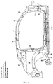
- FIG. 2 is a side view of the right side of the vehicle in FIG. 1 .
- FIG. 3 is a plan view illustrating the upper vehicle-body structure.
- FIG. 4 is an enlarged plan view of a main portion shown in FIG. 3 .
- FIG. 5 is an enlarged plan view of the main portion illustrated in a state in which a reinforcement member is removed from FIG. 3 .
- FIG. 6 is a cross-sectional view taken along line A-A from arrows in FIG. 3 .
- FIG. 7 is an exploded perspective view of a roof reinforcement and the reinforcement member.
- FIG. 8A to FIG. 8D are plan views illustrating other embodiments of the reinforcement member.
- a vehicle-body structure of an electric automobile that does not include an internal-combustion engine such as an engine for vehicle traveling, an exhaust pathway including an exhaust pipe, and a center tunnel portion that extends so as to be long in the vehicle front-rear direction is exemplified in the embodiments below, but the present invention is not only limited to the upper vehicle-body structure of the electric automobile.
- a dash panel (in detail, a dash lower panel) that separates a motor room of the vehicle front portion and a vehicle interior behind the motor room in the vehicle front-rear direction is provided, and a substantially flat-shaped front floor panel 1 (hereinafter simply referred to as the "front floor panel 1") is disposed on a lower rear-end portion of the dash panel in a continuous manner.
- the floor panel 1 forms a floor surface of the vehicle interior, and side sills 2 each having a closed cross-section structure that extend substantially in the vehicle front-rear direction are provided on both of left and right sides of the floor panel 1 in the vehicle width direction.
- the side sills 2 are vehicle body strength members each having a side sill closed cross-section portion extending substantially in the vehicle front-rear direction obtained by fixing a side sill inner portion 2a and a side sill outer portion 2b to each other by joining.
- a front-portion cross member 3 (so-called No. 2 cross member) that linearly couples front portions of the pair of left and right side sills 2, 2 to each other in the vehicle width direction is provided.
- the front-portion cross member 3 is formed by a member having a hat-shaped cross section, and a closed cross-section portion linearly extending substantially in the vehicle width direction is formed between the floor panel 1 and the front-portion cross member 3 by fixing the lower flange of the member to the upper surface of the floor panel 1 by joining, particularly welding.
- the front-portion cross member 3 is provided in a position corresponding to the lower portion of the front side of a front seat.
- an intermediate cross member 4 (so-called No. 2.5 cross member) that linearly couples intermediate portions of the pair of left and right side sills 2 in the vehicle front-rear direction to each other in the vehicle width direction is provided.
- the intermediate cross member 4 is also formed by a member having a hat-shaped cross section, and a closed cross-section portion linearly extending substantially in the vehicle width direction is formed between the floor panel 1 and the intermediate cross member 4 by fixing a lower flange of the member to the upper surface of the floor panel 1 by joining, particularly welding.
- the intermediate cross member 4 is provided in a position corresponding to the lower portion of the rear side of the front seat.
- the intermediate cross member 4 and the front-portion cross member 3 are disposed so as to be parallel to each other.
- a kick-up portion 5 that rises upward and then extends rearward from an upper end thereof is formed.
- a cross member (so-called No. 3 cross member) extending substantially in the vehicle width direction is provided.
- a closed cross-section portion extending substantially in the vehicle width direction is formed between the cross member and the kick-up portion 5.
- a rear seat pan 6 for mounting the rear seat is provided on the rear side of the kick-up portion 5. Further, a rear floor pan 7 that forms a floor surface of a trunk is disposed on the rear side of the rear seat pan 6 in a continuous manner. In the intermediate portion of the rear floor pan 7 in the vehicle width direction, a trunk recessed portion is formed in a recessed manner.
- a rear-portion cross member 8 (so-called No. 4 cross member) that extends substantially in the vehicle width direction across a rear end portion of the rear seat pan 6 and a front end portion of the rear floor pan 7 is provided, and a closed cross-section portion extending substantially in the vehicle width direction is formed between the rear-portion cross member 8 and each of the rear seat pan 6 and the rear floor pan 7.
- the rear-portion cross member 8 includes a rear-portion cross member upper portion and a rear-portion cross member lower portion, and a closed cross-section portion extending substantially in the vehicle width direction is formed between the rear-portion cross member upper portion and the rear-portion cross member lower portion.
- a partial tunnel portion 9 that protrudes into the vehicle interior is integrally formed or formed in an integral manner in the center of the front portion of the floor panel 1 in the vehicle width direction.
- the tunnel portion 9 is a partial portion only formed between the rear end of the lower portion of the dash panel and a portion immediately before the front-portion cross member 3.
- a floor frame 10 (in detail, a floor frame upper portion) is fixed to the intermediate portion between the tunnel portion 9, which is located in a central portion in the vehicle width direction, and a side sill 2, which is located in a side portion in the vehicle width direction, in the vehicle width direction by joining, particularly welding.
- the floor frame 10 has a hat cross-sectional shape, and a closed cross-section portion extending substantially in the vehicle front-rear direction is formed between the floor frame 10 and each of the floor panel 1 and the lower portion of the dash panel by joining, particularly welding, a lower flange of the floor frame 10 across the floor panel 1 and the lower portion of the dash panel.
- a bracket 11 provided to protrude that is substantially M-shaped in front view of the vehicle is fixed so as to protrude in an intermediate portion between the front-portion cross member 3 and the intermediate cross member 4 in the vehicle front-rear direction and in a central position in the vehicle width direction.
- a kick-up portion reinforcement member 12 having an upper wall, left and right side walls, and a front wall is provided on a central portion immediately before the kick-up portion 5 in the vehicle width direction, and is formed so as to reinforce the kick-up portion 5 by fixing a lower flange of the kick-up portion reinforcement member 12 to the floor panel 1 and the kick-up portion 5 by joining, particularly welding.
- front pillar portions 13 each having a closed cross-section structure that are located on portions on both of left and right sides of a front windshield (so-called front window glass) in the vehicle width direction and extend from front end portions of roof side rails 21 described below in a forwardly descending form are provided.
- the front pillar portion 13 is a vehicle body strength member having a front pillar closed cross-section portion along the longitudinal direction thereof obtained by fixing a front pillar outer portion and a front pillar inner portion to each other by joining, particularly welding.
- Hinge pillar portions 16 each having a closed cross-section structure that extend substantially downward from the front end portions of the pair of left and right front pillar portions 13, 13 to support the door hinge members are provided.
- Each of the hinge pillar portions 16 is a vehicle body strength member extending substantially in the vehicle up-down direction obtained by fixing a hinge pillar inner portion 19 horizontally divided into a hinge pillar upper-inner portion 17 and a hinge pillar lower-inner portion 18, and a hinge pillar outer portion 20 to each other by joining, particularly welding.
- a hinge pillar closed cross-section portion extending substantially in the vehicle up-down direction is formed between the hinge pillar inner portion 19 and the hinge pillar outer portion 20.
- the hinge pillar portion 16 is a vehicle body strength member that couples a front end of the side sill 2 and an inclined lower end portion of the front pillar portion 13 to each other in the up-down direction.
- a pair of left and right roof side rails 21, 21 is provided.
- the pair of left and right roof side rails 21, 21 is continuous from the front pillar portions 13 to the vehicle rear side, extends substantially in the vehicle front-rear direction in a state of being closer to horizontal than the front pillar portions 13, and has an upper portion to which a roof panel is joined, particularly welded.
- the roof side rails 21 are vehicle body strength members extending substantially along the vehicle front-rear direction on both of left and right sides of the upper portion of the vehicle body in the vehicle width direction, and each of the roof side rails 21 is a vehicle body strength member that is obtained by fixing a roof side rail inner portion and a roof side rail outer portion to each other by joining, particularly welding, and form a roof side rail closed cross-section portion extending substantially in the vehicle front-rear direction.
- rear pillar portions 24 each having a closed cross-section structure that are continuous from the roof side rail 21 to the vehicle rear side and extend to the rear side while curving in a front-high rear-low shape are provided.
- Each of the rear pillar portions 24 is a vehicle body strength member in which a rear pillar closed cross-section portion along the longitudinal direction of the rear pillar portion 24 is formed by fixing a rear pillar inner portion and a rear pillar outer portion to each other by joining, particularly welding.
- a front header 25 that extends substantially in the vehicle width direction between front end portions of the roof side rails 21 and has both of left and right end portions thereof fixed to the roof side rails 21 is provided.
- a rear header 26 that extends substantially in the vehicle width direction between upper end portions of the rear pillar portions 24 and has both of left and right end portions thereof fixed to the rear pillar portions 24 are provided.
- one or a plurality of roof reinforcements 27, 28, 29, and 30 spaced apart from each other in the vehicle front-rear direction are provided between the front header 25 and the rear header 26.
- Those roof reinforcements 27 to 30 extend substantially in the vehicle width direction between the pair of left and right roof side rails 21, 21, and each have both of left and right end portions thereof fixed to the roof side rails 21.
- Those roof reinforcements 27 to 30 are reinforcements each having a width (front-rear width) in the vehicle front-rear direction and bridging the pair of left and right roof side rails 21, 21 in the vehicle width direction.
- a roof panel (not shown) is provided above the pair of left and right roof side rails 21, the front header 25, the rear header 26, and the roof reinforcements 27 to 30.
- rear side frames 31 each having a closed cross-section structure that extend substantially in the vehicle front-rear direction are provided on both sides of the rear floor pan 7 in the vehicle width direction, and front end portions of the rear side frames 31 are disposed so as to extend frontward to positions that overlap with rear end portions of the side sills 2.
- a side panel inner portion 32 and a rear wheel well 33 are provided on the outer side of each of the rear side frames 31 in the vehicle width direction, and a gusset member 34 that couples a damper support portion on the upper end portion of the rear wheel well 33 and the rear pillar portion 24 in the vehicle front-rear direction in a substantially horizontal form is provided.
- a brace member 35 is provided so as to be continuous from an end portion of the rear cross member 8 in the vehicle width direction to the upper side of the vehicle.
- the brace member 35 is fixed to the inner surface of the rear wheel well 33 and the side panel inner portion 32 by joining, particularly welding, and a closed cross-section portion extending substantially in the vehicle up-down direction is formed between the brace member 35 and each of the side panel inner portion 32 and the rear wheel well 33.
- structure bodies 36 each having a closed cross sectional shape are provided.
- Each of the structure bodies 36 couples the rear portion of the roof side rail 21 corresponding to the roof reinforcement 30 located on the rearmost side of the vehicle out of the plurality of roof reinforcements 27 to 30 and the rear end portion of the side sill 2 below the rear portion in a substantially up-down direction of the vehicle.
- the structure body 36 also serves as a rearside hinge pillar.
- an annular structure body LS that is annularly continuous in side view of the vehicle is formed by the roof side rail 21 that forms an upper wall portion having a closed cross-section structure, the front pillar portion 13 that forms an oblique wall portion having a closed cross-section structure, the hinge pillar portion 16 that forms a front wall portion having a closed cross-section structure, the side sill 2 that forms a lower wall portion having a closed cross-section structure, and the structure body 36 that forms a rear wall portion having a closed cross-section structure.
- a door opening portion 37 without a center pillar is formed on the side portion of the vehicle by the elements 21, 13, 16, 2, and 36.
- the door opening portion 37 is opened and/or closed by a front-hinged front door and a rear-hinged rear door, for example.
- the front end of the front-hinged front door is attached to the hinge pillar portion 16 via a front door hinge member so as to be openable and closable, and the rear end of the rear-hinged rear door is attached to the structure body 36 via a rear door hinge member so as to be openable and closable.
- the structure body 36 is a vehicle body strength member extending in a substantially up-down direction of the vehicle on the rear portion of the door opening portion 37, and a front end pivotably supporting portion 40 of a trailing arm 39 in a torsion beam type rear suspension 38 serving as a rear suspension member of the vehicle is provided near the lower end portion of the structure body 36.
- the front end pivotably supporting portion 40 of the trailing arm 39 is particularly attached to an outer-side portion of the rear side frame 31 in the vehicle width direction via a support bracket.
- the trailing arm 39 in a torsion beam type rear suspension is Particularly exemplified as the rear suspension member in this embodiment, but the rear suspension member may be a suspension member in other types of rear suspensions.
- an opening of an opening portion 41 for disposing a quarter window is formed in the rear side of the upper portion of the structure body 36.
- Substantially the entire side surface of the vehicle body including the abovementioned elements, that is, the structure body 36, the roof side rail 21, the rear pillar portion 24, the side panel inner portion 32, and the side sills 2 is covered with a body side outer panel 42 serving as a vehicle body outer plate except for the opening portion 41 and the door opening portion 37.
- the roof reinforcement 28 that is the second reinforcement from the vehicle front side out of the plurality of roof reinforcements 27, 28, 29, and 30 illustrated in FIG. 3 has a cross sectional shape in the vehicle front-rear direction that is formed in a substantially W shape.
- substantially W-shaped roof reinforcement 28 is formed as illustrated in FIG. 6 and FIG. 7 .
- a substantially W shape is particularly obtained by integrally forming an upper wall 28a in an intermediate position in the vehicle front-rear direction, a pair of front and rear vertical walls 28b and 28c extending downward from both of front and rear ends of the upper wall 28a, a lower wall 28d extending frontward from a lower end of the vertical wall 28b on the front side, a lower wall 28e extending rearward from a lower end of the vertical wall 28c on the rear side, a protruding wall 28f extending upward from a front end of the lower wall 28d on the front side, a protruding wall 28g extending upward from a rear end of the lower wall 28e on the rear side, a flange portion 28h extending frontward from an upper end of the protruding wall 28f on the front side, and a flange portion 28i extending rearward from an upper end of the protruding wall 28g on the rear side.
- the upper wall 28a and each of the front and rear flange portions 28h and 28i are formed to be located at substantially the same height, and the front and rear lower walls 28d and 28e are also formed to be located at substantially the same height (see FIG. 6 ).
- tongue-shaped protruding portions 28j, 28j protruding outward in the vehicle width direction from both ends of the flange portion 28h on the front side in the vehicle width direction are integrally formed
- tongue-shaped protruding portions 28k, 28k protruding outward in the vehicle width direction from both ends of the flange portion 28i on the rear side in the vehicle width direction are also integrally formed.
- the roof reinforcement 28 is installed between the pair of left and right roof side rails 21, 21 in the vehicle width direction by fixing those protruding portions 28j and 28k to the roof side rails 21 by joining by joining means such as spot welding.
- a reinforcement structure body 50 is fixed to the roof reinforcement 28 by joining, particularly welding.
- the reinforcement structure body 50 is obtained by integrally forming a first inclined reinforcement member 51 at least diagonally extending substantially in the vehicle front-rear direction from a front portion on the right side in the vehicle width direction toward a rear portion on the left side in the vehicle width direction and fixed to the upper wall 28a and the flange portions 28h and 28i of the roof reinforcement 28 by joining, particularly welding, at a position at which a front end portion 51a and a rear end portion 51b of the first inclined reinforcement member 51 in the vehicle front-rear direction offset each other in the vehicle width direction, a second inclined reinforcement member 52 at least diagonally extending substantially in the vehicle front-rear direction from a front portion on the left side in the vehicle width direction toward a rear portion on the right side in the vehicle width direction and fixed to the upper wall 28a and the flange portions 28h and 28i of the roof reinforcement 28 by joining, particularly welding, at a position at which a front end portion 52a and a rear end portion
- both of the first inclined reinforcement member 51 and the second inclined reinforcement member 52 are formed by elongated members.
- two reinforcement members that is, the first inclined reinforcement member 51 and the second inclined reinforcement member 52 formed by elongated members are provided, and the inclined reinforcement members 51 and 52 are formed in a substantially X shape in plan view as illustrated in the same figure.
- the twisting behavior of the roof reinforcement 28 that occurs when the vehicle travels is suppressed by joining, particularly welding, the reinforcement member (at least one of the first inclined reinforcement member 51 and the second inclined reinforcement member 52) at least diagonally extending substantially in the vehicle front-rear direction to the roof reinforcement 28.
- the structure body 36 extending in a substantially up-down direction of the vehicle is provided on the rear portion of the door opening portion 37, and the trailing arm 39 in the torsion beam type rear suspension 38 serving as the rear suspension member is pivotally supported on a place near the lower end portion of the structure body 36 in order to dispose the front-hinged front door and the rear-hinged rear door on a vehicle side portion, suspension load is input to the roof side rail 21 from the trailing arm 39 via the structure body 36, and the load is transmitted to the roof reinforcement 28.
- the roof reinforcement 28 tends to twist due to the sizes of the loads input to the left side and the right side of the roof reinforcement 28 in the vehicle width direction being different when the vehicle corners, but the inclined reinforcement members 51 and 52 suppress the twisting behavior.
- the reinforcement structure body 50 formed by the elements 51 to 57 is formed by punching a metal flat plate by a press apparatus, and a plurality of places of the portions at which the reinforcement structure body 50 corresponds to the upper wall 28a and the flange portions 28h and 28i of the roof reinforcement 28 are fixed to the roof reinforcement 28 by joining by joining means such as spot welding.
- the length of the reinforcement structure body 50 in the vehicle width direction is set to be within a range of from about 70% to about 75% of the length of the roof reinforcement 28 in the vehicle width direction, and the reinforcement structure body 50 is fixed to the substantially central portion of the roof reinforcement 28 in the vehicle width direction by joining without leaning to the left or the right.
- the length is not limited to the abovementioned numerical values of length.
- the first inclined reinforcement member 51 particularly has an inclined angle ⁇ 1 of from about 78 degrees to about 81 degrees with respect to the virtual centerline CL extending in the vehicle center in the vehicle front-rear direction in the clockwise direction in plan view.
- the second inclined reinforcement member 52 has an inclined angle ⁇ 2 of from about 78 degrees to about 81 degrees with respect to the virtual centerline CL extending in the vehicle center in the vehicle front-rear direction in the counterclockwise direction in plan view.
- the inclined angles are not limited to those numerical values.
- the front wall portion 53, the rear wall portion 54, the left side wall portion 55, and the right side wall portion 56 are particularly integrally formed so that the reinforcement structure body 50 is easily loaded and the handleability thereof is improved when the reinforcement structure body 50 is transported.
- arrow F indicates the vehicle front side
- arrow R indicates the vehicle rear side
- arrow UP indicates the vehicle upper side
- the upper vehicle-body structure of the embodiment above includes: the pair of roof side rails 21 extending substantially along the vehicle front-rear direction on both of left and right sides of the upper portion of the vehicle body in the vehicle width direction; the roof reinforcement 28 having a width in the vehicle front-rear direction and serving as a bridge between the pair of roof side rails 21, 21 in the vehicle width direction; and the reinforcement member (at least one reinforcement member out of the first inclined reinforcement member 51 and the second inclined reinforcement member 52) provided on the roof reinforcement 28 and at least diagonally extending substantially in the vehicle front-rear direction, the reinforcement member being joined, particularly welded, to the roof reinforcement 28 at the positions at which the front end portion and the rear end portion of the reinforcement member in the vehicle front-rear direction offset each other in the vehicle width direction (see FIG. 3 , FIG. 4 , and FIG. 7 ).
- the reinforcement member at least diagonally extending substantially in the vehicle front-rear direction (at least one of the first inclined reinforcement member 51 and the second inclined reinforcement member 52) is joined, particularly welded, to the roof reinforcement 28, and hence the twisting behavior of the roof reinforcement 28 that occurs when the vehicle travels can be suppressed while saving weight.
- the reinforcement member (the first inclined reinforcement member 51 and the second inclined reinforcement member 52) is formed by an elongated member (see FIG. 4 and FIG. 7 ) .
- weight can be saved as compared to a structure in which the entire upper portion of the roof reinforcement 28 is covered with one rectangular plate.
- the reinforcement member (the first inclined reinforcement member 51 and the second inclined reinforcement member 52) formed by the elongated member includes one or a plurality of reinforcement members, and the plurality of the reinforcement members (the first inclined reinforcement member 51 and the second inclined reinforcement member 52) form a substantially X shape in plan view (see FIG. 4 and FIG. 7 ).
- the reinforcement members (the first inclined reinforcement member 51 and the second inclined reinforcement member 52) formed by the elongated members are combined in a substantially X shape in plan view, and hence the twisting prevention effect of the roof reinforcement 28 can be increased.
- the door opening portion 37 without a center pillar is formed in the vehicle side portion by each of the roof side rails 21 on which the roof reinforcement 28 is provided (see FIG. 1 and FIG. 2 ).
- the twisting behavior easily occurs for the roof reinforcement 28 due to the absence of a center pillar, but the twisting behavior of the roof reinforcement 28 can be suppressed by the reinforcement member (the first inclined reinforcement member 51 and/or the second inclined reinforcement member 52).
- the structure body 36 extending in a substantially up-down direction of the vehicle is provided on the rear portion of the door opening portion 37, and the rear suspension member (see the trailing arm 39 of the torsion beam type rear suspension 38) of the vehicle is provided near the lower end portion of the structure body 36 (see FIG. 2 ).
- the load is input from the rear suspension member (see the trailing arm 39) of the vehicle to the structure body 36 extending in a substantially up-down direction via a place near the lower end portion of the structure body 36, and the load is transmitted to the roof reinforcement 28 via the roof side rails 21, but the twisting behavior of the roof reinforcement 28 can be suppressed by the reinforcement member (the first inclined reinforcement member 51 and/or the second inclined reinforcement member 52).
- FIG. 8A to FIG. 8D are plan views illustrating reinforcement members of other embodiments, and the right side of the figure is the vehicle front side and the left side of the figure is the vehicle rear side in each of FIG. 8A to FIG. 8D .
- the structure illustrated in FIG. 8A is obtained by forming a reinforcement structure body 50A with use of only the first inclined reinforcement member 51. By this configuration, the twisting behavior of the roof reinforcement 28 can be suppressed while saving weight.
- the structure illustrated in FIG. 8B is obtained by forming a reinforcement structure body 50B having a substantially X shape in plan view of the vehicle with use of the first inclined reinforcement member 51 and the second inclined reinforcement member 52.
- the twisting behavior of the roof reinforcement 28 can be further suppressed while saving weight.
- the structure illustrated in FIG. 8C is obtained by forming a reinforcement structure body 50C having a structure portion having a substantially X shape in plan view with use of the first inclined reinforcement member 51, the second inclined reinforcement member 52, the left side wall portion 55, and the right side wall portion 56.
- the twisting behavior of the roof reinforcement 28 can be suppressed even more while saving weight, and the handleability thereof can be improved.
- the structure illustrated in FIG. 8D is obtained by forming a reinforcement structure body 50D having a structure portion having a substantially X shape in plan view with use of the first inclined reinforcement member 51, the second inclined reinforcement member 52, the front wall portion 53, and the rear wall portion 54.
- the twisting behavior of the roof reinforcement 28 can be further suppressed while saving weight, and the handleability thereof can be improved.
- FIG. 8A to FIG. 8D the same parts as those in the previous figure are denoted by the same reference characters, and detailed description thereof is omitted.
- the reinforcement member of the present invention corresponds to at least one reinforcement member out of the first inclined reinforcement member 51 and the second inclined reinforcement member 52 of the embodiments.
- the rear suspension member of the vehicle corresponds to the trailing arm 39 of the torsion beam type rear suspension 38.
- the present invention is not only limited to the configurations of the abovementioned embodiments.
- the present invention is useful for an upper vehicle-body structure in which a pair of roof side rails extending substantially along the vehicle front-rear direction is provided on both of left and right sides of an upper portion of a vehicle body in the vehicle width direction, and a roof reinforcement having a width in the vehicle front-rear direction and serving as a bridge between the pair of roof side rails in the vehicle width direction is provided.
Landscapes
- Engineering & Computer Science (AREA)
- Chemical & Material Sciences (AREA)
- Combustion & Propulsion (AREA)
- Transportation (AREA)
- Mechanical Engineering (AREA)
- Body Structure For Vehicles (AREA)
Applications Claiming Priority (1)
| Application Number | Priority Date | Filing Date | Title |
|---|---|---|---|
| JP2019105578A JP7322522B2 (ja) | 2019-06-05 | 2019-06-05 | 上部車体構造 |
Publications (1)
| Publication Number | Publication Date |
|---|---|
| EP3747741A1 true EP3747741A1 (de) | 2020-12-09 |
Family
ID=69845155
Family Applications (1)
| Application Number | Title | Priority Date | Filing Date |
|---|---|---|---|
| EP20163550.5A Withdrawn EP3747741A1 (de) | 2019-06-05 | 2020-03-17 | Obere fahrzeugkarosseriestruktur, fahrzeugkarosseriestruktur und fahrzeug |
Country Status (4)
| Country | Link |
|---|---|
| US (1) | US11192592B2 (de) |
| EP (1) | EP3747741A1 (de) |
| JP (1) | JP7322522B2 (de) |
| CN (1) | CN112046615B (de) |
Families Citing this family (8)
| Publication number | Priority date | Publication date | Assignee | Title |
|---|---|---|---|---|
| US11186319B2 (en) * | 2019-10-30 | 2021-11-30 | Nissan North America, Inc. | Vehicle body structure |
| US11926226B2 (en) | 2020-12-10 | 2024-03-12 | Hyundai Motor Company | Vehicle body |
| KR102960460B1 (ko) | 2020-12-10 | 2026-04-30 | 현대자동차주식회사 | 차량의 차체 |
| US11794813B2 (en) * | 2020-12-10 | 2023-10-24 | Hyundai Motor Company | Vehicle body and vehicle |
| JP7670568B2 (ja) | 2020-12-10 | 2025-04-30 | 現代自動車株式会社 | 車体 |
| JP7375956B2 (ja) * | 2020-12-14 | 2023-11-08 | トヨタ車体株式会社 | 車両用ルーフ構造 |
| US12441408B2 (en) * | 2022-08-03 | 2025-10-14 | Ford Global Technologies, Llc | Vehicle roof structure |
| JP7744316B2 (ja) * | 2022-09-30 | 2025-09-25 | 太平洋工業株式会社 | 車両用リンフォース |
Citations (6)
| Publication number | Priority date | Publication date | Assignee | Title |
|---|---|---|---|---|
| JP2003112656A (ja) | 2001-10-03 | 2003-04-15 | Toyota Motor Corp | 車両のルーフ構造 |
| JP2004168073A (ja) * | 2002-11-15 | 2004-06-17 | Nissan Motor Co Ltd | 車体上部構造 |
| EP1690780A2 (de) * | 2005-02-11 | 2006-08-16 | Audi Ag | Dachanordnung für Kraftfahrzeuge |
| US20130214559A1 (en) * | 2012-02-21 | 2013-08-22 | Toyota Motor Engineering & Manufacturing North America, Inc. | Lateral impact energy transfer rail |
| DE102017116752A1 (de) * | 2016-09-09 | 2018-03-15 | Suzuki Motor Corporation | Obere Fahrzeugkarosseriestruktur |
| US20180201325A1 (en) * | 2017-01-17 | 2018-07-19 | Ford Global Technologies, Llc | Roof frame including a brace reinforcing arched members |
Family Cites Families (19)
| Publication number | Priority date | Publication date | Assignee | Title |
|---|---|---|---|---|
| US2122444A (en) * | 1934-07-20 | 1938-07-05 | Briggs Mfg Co | Automobile body |
| US3408779A (en) * | 1966-06-27 | 1968-11-05 | Stanray Corp | X type panel roof sheet |
| US3823518A (en) * | 1973-01-05 | 1974-07-16 | Stanray Corp | Reinforced fiberglass plastic roof for box cars |
| TW556692U (en) * | 1997-01-31 | 2003-10-01 | Mazda Motor | Body structure for vehicle |
| JP4576771B2 (ja) * | 2001-08-21 | 2010-11-10 | マツダ株式会社 | 車両の側部車体構造 |
| JP2004142584A (ja) * | 2002-10-24 | 2004-05-20 | Fuji Heavy Ind Ltd | 自動車の車体後部構造 |
| JP4093025B2 (ja) * | 2002-11-15 | 2008-05-28 | 日産自動車株式会社 | 車体上部構造 |
| DE102004058831B3 (de) * | 2004-12-06 | 2006-10-19 | Daimlerchrysler Ag | Hilfsrahmen für einen Fahrgestellrahmen eines Nutzfahrzeugs |
| US7604286B2 (en) * | 2006-01-13 | 2009-10-20 | Nissan Motor Co., Ltd. | Roof structure of a vehicular body |
| DE102008058225A1 (de) * | 2008-11-19 | 2010-07-08 | Lanxess Deutschland Gmbh | Leichtbauteil in Hybridbauweise |
| JP6019735B2 (ja) * | 2011-08-29 | 2016-11-02 | 日産自動車株式会社 | 車体構造および車体の製造方法 |
| WO2014034586A1 (ja) * | 2012-08-27 | 2014-03-06 | 東レ株式会社 | 車両用ルーフ構造体 |
| SG2014011902A (en) * | 2013-04-09 | 2014-11-27 | Bombardier Transp Gmbh | Roof structure for a vehicle |
| US9156500B2 (en) * | 2013-10-09 | 2015-10-13 | Ford Global Technologies, Llc | Bowtie shaped roof bow |
| JP6217367B2 (ja) * | 2013-12-09 | 2017-10-25 | 三菱自動車工業株式会社 | 車両のルーフ構造 |
| JP6090241B2 (ja) * | 2014-06-18 | 2017-03-08 | マツダ株式会社 | サンルーフ付き自動車の上部車体構造 |
| JP6304066B2 (ja) * | 2015-02-18 | 2018-04-04 | マツダ株式会社 | 車両の上部車体構造 |
| CN205737720U (zh) * | 2016-06-30 | 2016-11-30 | 长城汽车股份有限公司 | 汽车顶盖前横梁结构及汽车顶部框架结构 |
| JP6900797B2 (ja) * | 2016-09-09 | 2021-07-07 | スズキ株式会社 | 車体上部構造 |
-
2019
- 2019-06-05 JP JP2019105578A patent/JP7322522B2/ja active Active
-
2020
- 2020-02-25 CN CN202010114702.8A patent/CN112046615B/zh active Active
- 2020-03-17 EP EP20163550.5A patent/EP3747741A1/de not_active Withdrawn
- 2020-03-18 US US16/822,053 patent/US11192592B2/en active Active
Patent Citations (6)
| Publication number | Priority date | Publication date | Assignee | Title |
|---|---|---|---|---|
| JP2003112656A (ja) | 2001-10-03 | 2003-04-15 | Toyota Motor Corp | 車両のルーフ構造 |
| JP2004168073A (ja) * | 2002-11-15 | 2004-06-17 | Nissan Motor Co Ltd | 車体上部構造 |
| EP1690780A2 (de) * | 2005-02-11 | 2006-08-16 | Audi Ag | Dachanordnung für Kraftfahrzeuge |
| US20130214559A1 (en) * | 2012-02-21 | 2013-08-22 | Toyota Motor Engineering & Manufacturing North America, Inc. | Lateral impact energy transfer rail |
| DE102017116752A1 (de) * | 2016-09-09 | 2018-03-15 | Suzuki Motor Corporation | Obere Fahrzeugkarosseriestruktur |
| US20180201325A1 (en) * | 2017-01-17 | 2018-07-19 | Ford Global Technologies, Llc | Roof frame including a brace reinforcing arched members |
Also Published As
| Publication number | Publication date |
|---|---|
| US20200385065A1 (en) | 2020-12-10 |
| CN112046615A (zh) | 2020-12-08 |
| CN112046615B (zh) | 2022-09-27 |
| US11192592B2 (en) | 2021-12-07 |
| JP2020196413A (ja) | 2020-12-10 |
| JP7322522B2 (ja) | 2023-08-08 |
Similar Documents
| Publication | Publication Date | Title |
|---|---|---|
| US11192592B2 (en) | Upper vehicle-body structure | |
| US8201873B2 (en) | Body structure of vehicle | |
| EP3816021B1 (de) | Fahrzeugkarosseriefrontstruktur eines fahrzeugs sowie fahrzeug | |
| US11155308B2 (en) | Vehicle side body structure | |
| EP3566931B1 (de) | Fahrzeugkarosseriestruktur und fahrzeug | |
| JP5321334B2 (ja) | 車両のカウル部構造 | |
| EP3718863B1 (de) | Fahrzeugseitenkarosseriestruktur und fahrzeug | |
| US11345407B2 (en) | Upper vehicle-body structure | |
| EP3632778B1 (de) | Fahrzeugfrontkarosseriestruktur und fahrzeug | |
| EP4144621A1 (de) | Struktur der unteren karosserie eines fahrzeugs | |
| JPS62181976A (ja) | 自動車の下部車体構造 | |
| JP4335841B2 (ja) | ハッチバック型車両の後部車体構造 | |
| EP1177968A2 (de) | Stossenergieabsorbierende Struktur für ein Kraftfahrzeug | |
| JP6958375B2 (ja) | 車両の後部車体構造 | |
| JP3274080B2 (ja) | 自動車のバックドア開口部の補強構造 | |
| WO2019198751A1 (ja) | 自動車の車体構造 | |
| JP2022043804A (ja) | 車両用ボデー | |
| JP2020044993A (ja) | 車両後部構造 | |
| JPH11245845A (ja) | キャブオーバ型トラックのキャブ構造 | |
| JPH02256570A (ja) | 車両の後部車体構造 | |
| JP2024011290A (ja) | 車両後部構造 | |
| JP2012171569A (ja) | 車両用ドアのドアミラー取付け構造 | |
| JP2020196412A (ja) | 上部車体構造 |
Legal Events
| Date | Code | Title | Description |
|---|---|---|---|
| PUAI | Public reference made under article 153(3) epc to a published international application that has entered the european phase |
Free format text: ORIGINAL CODE: 0009012 |
|
| STAA | Information on the status of an ep patent application or granted ep patent |
Free format text: STATUS: THE APPLICATION HAS BEEN PUBLISHED |
|
| AK | Designated contracting states |
Kind code of ref document: A1 Designated state(s): AL AT BE BG CH CY CZ DE DK EE ES FI FR GB GR HR HU IE IS IT LI LT LU LV MC MK MT NL NO PL PT RO RS SE SI SK SM TR |
|
| AX | Request for extension of the european patent |
Extension state: BA ME |
|
| STAA | Information on the status of an ep patent application or granted ep patent |
Free format text: STATUS: THE APPLICATION IS DEEMED TO BE WITHDRAWN |
|
| 18D | Application deemed to be withdrawn |
Effective date: 20210610 |