EP3747623B1 - Injection molding mold for an injection molding unit of an injection stretch blow molding machine, method for molding a preform, and a method for molding a container - Google Patents
Injection molding mold for an injection molding unit of an injection stretch blow molding machine, method for molding a preform, and a method for molding a container Download PDFInfo
- Publication number
- EP3747623B1 EP3747623B1 EP20020298.4A EP20020298A EP3747623B1 EP 3747623 B1 EP3747623 B1 EP 3747623B1 EP 20020298 A EP20020298 A EP 20020298A EP 3747623 B1 EP3747623 B1 EP 3747623B1
- Authority
- EP
- European Patent Office
- Prior art keywords
- preform
- mold
- forming portion
- molding
- injection
- Prior art date
- Legal status (The legal status is an assumption and is not a legal conclusion. Google has not performed a legal analysis and makes no representation as to the accuracy of the status listed.)
- Active
Links
- 238000001746 injection moulding Methods 0.000 title claims description 96
- 238000000465 moulding Methods 0.000 title claims description 74
- 238000010103 injection stretch blow moulding Methods 0.000 title claims description 46
- 238000000034 method Methods 0.000 title claims description 22
- 239000010410 layer Substances 0.000 claims description 60
- 238000000071 blow moulding Methods 0.000 claims description 57
- 230000015572 biosynthetic process Effects 0.000 claims description 42
- 230000002093 peripheral effect Effects 0.000 claims description 41
- 239000006185 dispersion Substances 0.000 claims description 36
- 239000011347 resin Substances 0.000 claims description 29
- 229920005989 resin Polymers 0.000 claims description 29
- 238000001816 cooling Methods 0.000 claims description 21
- 230000001174 ascending effect Effects 0.000 claims description 14
- 239000002344 surface layer Substances 0.000 claims description 8
- 238000002347 injection Methods 0.000 description 28
- 239000007924 injection Substances 0.000 description 28
- 238000007664 blowing Methods 0.000 description 7
- 229920000139 polyethylene terephthalate Polymers 0.000 description 6
- 239000005020 polyethylene terephthalate Substances 0.000 description 6
- 238000012360 testing method Methods 0.000 description 6
- 239000000463 material Substances 0.000 description 5
- 241000446313 Lamella Species 0.000 description 4
- 238000005259 measurement Methods 0.000 description 4
- 230000001133 acceleration Effects 0.000 description 3
- 239000012141 concentrate Substances 0.000 description 3
- 230000003111 delayed effect Effects 0.000 description 3
- 238000002425 crystallisation Methods 0.000 description 2
- 230000008025 crystallization Effects 0.000 description 2
- 230000000694 effects Effects 0.000 description 2
- 238000012546 transfer Methods 0.000 description 2
- 238000000748 compression moulding Methods 0.000 description 1
- 238000007796 conventional method Methods 0.000 description 1
- 230000001419 dependent effect Effects 0.000 description 1
- 238000000151 deposition Methods 0.000 description 1
- 230000002349 favourable effect Effects 0.000 description 1
- 230000009969 flowable effect Effects 0.000 description 1
- 238000004519 manufacturing process Methods 0.000 description 1
- -1 polyethylene terephthalate Polymers 0.000 description 1
- 238000011160 research Methods 0.000 description 1
- 239000000243 solution Substances 0.000 description 1
- 238000010998 test method Methods 0.000 description 1
Images


Classifications
-
- B—PERFORMING OPERATIONS; TRANSPORTING
- B29—WORKING OF PLASTICS; WORKING OF SUBSTANCES IN A PLASTIC STATE IN GENERAL
- B29C—SHAPING OR JOINING OF PLASTICS; SHAPING OF MATERIAL IN A PLASTIC STATE, NOT OTHERWISE PROVIDED FOR; AFTER-TREATMENT OF THE SHAPED PRODUCTS, e.g. REPAIRING
- B29C45/00—Injection moulding, i.e. forcing the required volume of moulding material through a nozzle into a closed mould; Apparatus therefor
- B29C45/17—Component parts, details or accessories; Auxiliary operations
- B29C45/26—Moulds
- B29C45/261—Moulds having tubular mould cavities
-
- B—PERFORMING OPERATIONS; TRANSPORTING
- B29—WORKING OF PLASTICS; WORKING OF SUBSTANCES IN A PLASTIC STATE IN GENERAL
- B29C—SHAPING OR JOINING OF PLASTICS; SHAPING OF MATERIAL IN A PLASTIC STATE, NOT OTHERWISE PROVIDED FOR; AFTER-TREATMENT OF THE SHAPED PRODUCTS, e.g. REPAIRING
- B29C49/00—Blow-moulding, i.e. blowing a preform or parison to a desired shape within a mould; Apparatus therefor
- B29C49/02—Combined blow-moulding and manufacture of the preform or the parison
- B29C49/06—Injection blow-moulding
-
- B—PERFORMING OPERATIONS; TRANSPORTING
- B29—WORKING OF PLASTICS; WORKING OF SUBSTANCES IN A PLASTIC STATE IN GENERAL
- B29C—SHAPING OR JOINING OF PLASTICS; SHAPING OF MATERIAL IN A PLASTIC STATE, NOT OTHERWISE PROVIDED FOR; AFTER-TREATMENT OF THE SHAPED PRODUCTS, e.g. REPAIRING
- B29C45/00—Injection moulding, i.e. forcing the required volume of moulding material through a nozzle into a closed mould; Apparatus therefor
- B29C45/17—Component parts, details or accessories; Auxiliary operations
- B29C45/26—Moulds
- B29C45/261—Moulds having tubular mould cavities
- B29C45/2612—Moulds having tubular mould cavities for manufacturing tubular articles with an annular groove
-
- B—PERFORMING OPERATIONS; TRANSPORTING
- B29—WORKING OF PLASTICS; WORKING OF SUBSTANCES IN A PLASTIC STATE IN GENERAL
- B29C—SHAPING OR JOINING OF PLASTICS; SHAPING OF MATERIAL IN A PLASTIC STATE, NOT OTHERWISE PROVIDED FOR; AFTER-TREATMENT OF THE SHAPED PRODUCTS, e.g. REPAIRING
- B29C45/00—Injection moulding, i.e. forcing the required volume of moulding material through a nozzle into a closed mould; Apparatus therefor
- B29C45/17—Component parts, details or accessories; Auxiliary operations
- B29C45/76—Measuring, controlling or regulating
- B29C45/78—Measuring, controlling or regulating of temperature
-
- B—PERFORMING OPERATIONS; TRANSPORTING
- B29—WORKING OF PLASTICS; WORKING OF SUBSTANCES IN A PLASTIC STATE IN GENERAL
- B29C—SHAPING OR JOINING OF PLASTICS; SHAPING OF MATERIAL IN A PLASTIC STATE, NOT OTHERWISE PROVIDED FOR; AFTER-TREATMENT OF THE SHAPED PRODUCTS, e.g. REPAIRING
- B29C49/00—Blow-moulding, i.e. blowing a preform or parison to a desired shape within a mould; Apparatus therefor
- B29C49/02—Combined blow-moulding and manufacture of the preform or the parison
- B29C49/06—Injection blow-moulding
- B29C49/061—Injection blow-moulding with parison holding means displaceable between injection and blow stations
- B29C49/062—Injection blow-moulding with parison holding means displaceable between injection and blow stations following an arcuate path, e.g. rotary or oscillating-type
-
- B—PERFORMING OPERATIONS; TRANSPORTING
- B29—WORKING OF PLASTICS; WORKING OF SUBSTANCES IN A PLASTIC STATE IN GENERAL
- B29C—SHAPING OR JOINING OF PLASTICS; SHAPING OF MATERIAL IN A PLASTIC STATE, NOT OTHERWISE PROVIDED FOR; AFTER-TREATMENT OF THE SHAPED PRODUCTS, e.g. REPAIRING
- B29C49/00—Blow-moulding, i.e. blowing a preform or parison to a desired shape within a mould; Apparatus therefor
- B29C49/08—Biaxial stretching during blow-moulding
- B29C49/10—Biaxial stretching during blow-moulding using mechanical means for prestretching
- B29C49/12—Stretching rods
-
- B—PERFORMING OPERATIONS; TRANSPORTING
- B29—WORKING OF PLASTICS; WORKING OF SUBSTANCES IN A PLASTIC STATE IN GENERAL
- B29C—SHAPING OR JOINING OF PLASTICS; SHAPING OF MATERIAL IN A PLASTIC STATE, NOT OTHERWISE PROVIDED FOR; AFTER-TREATMENT OF THE SHAPED PRODUCTS, e.g. REPAIRING
- B29C49/00—Blow-moulding, i.e. blowing a preform or parison to a desired shape within a mould; Apparatus therefor
- B29C49/28—Blow-moulding apparatus
- B29C49/30—Blow-moulding apparatus having movable moulds or mould parts
- B29C49/36—Blow-moulding apparatus having movable moulds or mould parts rotatable about one axis
-
- B—PERFORMING OPERATIONS; TRANSPORTING
- B29—WORKING OF PLASTICS; WORKING OF SUBSTANCES IN A PLASTIC STATE IN GENERAL
- B29C—SHAPING OR JOINING OF PLASTICS; SHAPING OF MATERIAL IN A PLASTIC STATE, NOT OTHERWISE PROVIDED FOR; AFTER-TREATMENT OF THE SHAPED PRODUCTS, e.g. REPAIRING
- B29C49/00—Blow-moulding, i.e. blowing a preform or parison to a desired shape within a mould; Apparatus therefor
- B29C49/42—Component parts, details or accessories; Auxiliary operations
- B29C49/48—Moulds
-
- B—PERFORMING OPERATIONS; TRANSPORTING
- B29—WORKING OF PLASTICS; WORKING OF SUBSTANCES IN A PLASTIC STATE IN GENERAL
- B29C—SHAPING OR JOINING OF PLASTICS; SHAPING OF MATERIAL IN A PLASTIC STATE, NOT OTHERWISE PROVIDED FOR; AFTER-TREATMENT OF THE SHAPED PRODUCTS, e.g. REPAIRING
- B29C49/00—Blow-moulding, i.e. blowing a preform or parison to a desired shape within a mould; Apparatus therefor
- B29C49/42—Component parts, details or accessories; Auxiliary operations
- B29C49/64—Heating or cooling preforms, parisons or blown articles
- B29C49/6409—Thermal conditioning of preforms
- B29C49/6436—Thermal conditioning of preforms characterised by temperature differential
- B29C49/6454—Thermal conditioning of preforms characterised by temperature differential through the preform thickness
-
- B—PERFORMING OPERATIONS; TRANSPORTING
- B29—WORKING OF PLASTICS; WORKING OF SUBSTANCES IN A PLASTIC STATE IN GENERAL
- B29B—PREPARATION OR PRETREATMENT OF THE MATERIAL TO BE SHAPED; MAKING GRANULES OR PREFORMS; RECOVERY OF PLASTICS OR OTHER CONSTITUENTS OF WASTE MATERIAL CONTAINING PLASTICS
- B29B11/00—Making preforms
- B29B11/06—Making preforms by moulding the material
- B29B11/08—Injection moulding
-
- B—PERFORMING OPERATIONS; TRANSPORTING
- B29—WORKING OF PLASTICS; WORKING OF SUBSTANCES IN A PLASTIC STATE IN GENERAL
- B29C—SHAPING OR JOINING OF PLASTICS; SHAPING OF MATERIAL IN A PLASTIC STATE, NOT OTHERWISE PROVIDED FOR; AFTER-TREATMENT OF THE SHAPED PRODUCTS, e.g. REPAIRING
- B29C49/00—Blow-moulding, i.e. blowing a preform or parison to a desired shape within a mould; Apparatus therefor
- B29C49/02—Combined blow-moulding and manufacture of the preform or the parison
- B29C2049/023—Combined blow-moulding and manufacture of the preform or the parison using inherent heat of the preform, i.e. 1 step blow moulding
-
- B—PERFORMING OPERATIONS; TRANSPORTING
- B29—WORKING OF PLASTICS; WORKING OF SUBSTANCES IN A PLASTIC STATE IN GENERAL
- B29C—SHAPING OR JOINING OF PLASTICS; SHAPING OF MATERIAL IN A PLASTIC STATE, NOT OTHERWISE PROVIDED FOR; AFTER-TREATMENT OF THE SHAPED PRODUCTS, e.g. REPAIRING
- B29C2949/00—Indexing scheme relating to blow-moulding
- B29C2949/07—Preforms or parisons characterised by their configuration
- B29C2949/076—Preforms or parisons characterised by their configuration characterised by the shape
- B29C2949/0761—Preforms or parisons characterised by their configuration characterised by the shape characterised by overall the shape
- B29C2949/0762—Conical
-
- B—PERFORMING OPERATIONS; TRANSPORTING
- B29—WORKING OF PLASTICS; WORKING OF SUBSTANCES IN A PLASTIC STATE IN GENERAL
- B29C—SHAPING OR JOINING OF PLASTICS; SHAPING OF MATERIAL IN A PLASTIC STATE, NOT OTHERWISE PROVIDED FOR; AFTER-TREATMENT OF THE SHAPED PRODUCTS, e.g. REPAIRING
- B29C2949/00—Indexing scheme relating to blow-moulding
- B29C2949/07—Preforms or parisons characterised by their configuration
- B29C2949/076—Preforms or parisons characterised by their configuration characterised by the shape
- B29C2949/0768—Preforms or parisons characterised by their configuration characterised by the shape characterised by the shape of specific parts of preform
- B29C2949/077—Preforms or parisons characterised by their configuration characterised by the shape characterised by the shape of specific parts of preform characterised by the neck
- B29C2949/0771—Wide-mouth
-
- B—PERFORMING OPERATIONS; TRANSPORTING
- B29—WORKING OF PLASTICS; WORKING OF SUBSTANCES IN A PLASTIC STATE IN GENERAL
- B29C—SHAPING OR JOINING OF PLASTICS; SHAPING OF MATERIAL IN A PLASTIC STATE, NOT OTHERWISE PROVIDED FOR; AFTER-TREATMENT OF THE SHAPED PRODUCTS, e.g. REPAIRING
- B29C2949/00—Indexing scheme relating to blow-moulding
- B29C2949/20—Preforms or parisons whereby a specific part is made of only one component, e.g. only one layer
- B29C2949/22—Preforms or parisons whereby a specific part is made of only one component, e.g. only one layer at neck portion
-
- B—PERFORMING OPERATIONS; TRANSPORTING
- B29—WORKING OF PLASTICS; WORKING OF SUBSTANCES IN A PLASTIC STATE IN GENERAL
- B29C—SHAPING OR JOINING OF PLASTICS; SHAPING OF MATERIAL IN A PLASTIC STATE, NOT OTHERWISE PROVIDED FOR; AFTER-TREATMENT OF THE SHAPED PRODUCTS, e.g. REPAIRING
- B29C2949/00—Indexing scheme relating to blow-moulding
- B29C2949/20—Preforms or parisons whereby a specific part is made of only one component, e.g. only one layer
- B29C2949/24—Preforms or parisons whereby a specific part is made of only one component, e.g. only one layer at flange portion
-
- B—PERFORMING OPERATIONS; TRANSPORTING
- B29—WORKING OF PLASTICS; WORKING OF SUBSTANCES IN A PLASTIC STATE IN GENERAL
- B29C—SHAPING OR JOINING OF PLASTICS; SHAPING OF MATERIAL IN A PLASTIC STATE, NOT OTHERWISE PROVIDED FOR; AFTER-TREATMENT OF THE SHAPED PRODUCTS, e.g. REPAIRING
- B29C2949/00—Indexing scheme relating to blow-moulding
- B29C2949/20—Preforms or parisons whereby a specific part is made of only one component, e.g. only one layer
- B29C2949/26—Preforms or parisons whereby a specific part is made of only one component, e.g. only one layer at body portion
-
- B—PERFORMING OPERATIONS; TRANSPORTING
- B29—WORKING OF PLASTICS; WORKING OF SUBSTANCES IN A PLASTIC STATE IN GENERAL
- B29C—SHAPING OR JOINING OF PLASTICS; SHAPING OF MATERIAL IN A PLASTIC STATE, NOT OTHERWISE PROVIDED FOR; AFTER-TREATMENT OF THE SHAPED PRODUCTS, e.g. REPAIRING
- B29C2949/00—Indexing scheme relating to blow-moulding
- B29C2949/20—Preforms or parisons whereby a specific part is made of only one component, e.g. only one layer
- B29C2949/28—Preforms or parisons whereby a specific part is made of only one component, e.g. only one layer at bottom portion
-
- B—PERFORMING OPERATIONS; TRANSPORTING
- B29—WORKING OF PLASTICS; WORKING OF SUBSTANCES IN A PLASTIC STATE IN GENERAL
- B29C—SHAPING OR JOINING OF PLASTICS; SHAPING OF MATERIAL IN A PLASTIC STATE, NOT OTHERWISE PROVIDED FOR; AFTER-TREATMENT OF THE SHAPED PRODUCTS, e.g. REPAIRING
- B29C45/00—Injection moulding, i.e. forcing the required volume of moulding material through a nozzle into a closed mould; Apparatus therefor
- B29C45/17—Component parts, details or accessories; Auxiliary operations
- B29C45/26—Moulds
- B29C45/2618—Moulds having screw-threaded mould walls
-
- B—PERFORMING OPERATIONS; TRANSPORTING
- B29—WORKING OF PLASTICS; WORKING OF SUBSTANCES IN A PLASTIC STATE IN GENERAL
- B29K—INDEXING SCHEME ASSOCIATED WITH SUBCLASSES B29B, B29C OR B29D, RELATING TO MOULDING MATERIALS OR TO MATERIALS FOR MOULDS, REINFORCEMENTS, FILLERS OR PREFORMED PARTS, e.g. INSERTS
- B29K2067/00—Use of polyesters or derivatives thereof, as moulding material
- B29K2067/003—PET, i.e. poylethylene terephthalate
-
- B—PERFORMING OPERATIONS; TRANSPORTING
- B29—WORKING OF PLASTICS; WORKING OF SUBSTANCES IN A PLASTIC STATE IN GENERAL
- B29K—INDEXING SCHEME ASSOCIATED WITH SUBCLASSES B29B, B29C OR B29D, RELATING TO MOULDING MATERIALS OR TO MATERIALS FOR MOULDS, REINFORCEMENTS, FILLERS OR PREFORMED PARTS, e.g. INSERTS
- B29K2105/00—Condition, form or state of moulded material or of the material to be shaped
- B29K2105/25—Solid
- B29K2105/253—Preform
- B29K2105/258—Tubular
-
- B—PERFORMING OPERATIONS; TRANSPORTING
- B29—WORKING OF PLASTICS; WORKING OF SUBSTANCES IN A PLASTIC STATE IN GENERAL
- B29L—INDEXING SCHEME ASSOCIATED WITH SUBCLASS B29C, RELATING TO PARTICULAR ARTICLES
- B29L2031/00—Other particular articles
- B29L2031/712—Containers; Packaging elements or accessories, Packages
- B29L2031/7158—Bottles
Definitions
- the present invention relates to an injection mold for a molding unit of an injection stretch blow molding machine, a method for molding a preform, and a method for molding a container.
- the invention relates to an injection molding mold according to the pre-characterizing features of claim 1, a preform molding method according to the pre-characterizing features of claim 7, and a container molding method according to the pre-characterizing features of claim 11.
- injection stretch blow molding machines are used to mold containers.
- the injection stretch blow molding machine is provided with three stations, i.e. an injection molding unit into which a molten resin is fed from a connected injection device, a stretch blow molding unit for molding a preform molded by the injection molding unit into a container, and an ejection unit for transferring the container molded by the stretch blow molding unit out of the machine.
- the three stations are disposed in the same circumference at the same angular intervals, and a rotating plate unit having a rotating plate, which transfers the molded preform and container by circular movement, is provided above the three stations.
- the aforementioned rotating plate of the injection stretch blow molding machine has lip molds on its bottom surface.
- the lip mold is used for forming an outer peripheral surface of a preform mouth portion, and for transferring the molded preform and container by catching the mouth portion of the preform.
- the injection molding unit, the stretch blow molding unit, and the ejection unit are disposed about a rotational axis of the rotating plate at the same angular intervals (120 degrees).
- the lip molds provided on the bottom surface of the rotating plate correspond to the injection molding unit, the stretch blow molding unit, and the ejection unit.
- the descent of the lip mold forms an injection molding mold in the injection molding unit.
- the descent of the lip mold forms a stretch blow molding mold in the stretch blow molding unit.
- the injection molding mold formed in the injection molding unit is constituted of a combination of the descended lip mold, a cavity mold fixed in the injection molding unit, and a core mold that is movable upward and downward in the injection molding unit.
- the lip mold is overlaid on the cavity mold fixed in the injection molding unit, and the core mold, which is movable upward and downward in the injection molding unit, is inserted into the cavity mold through the lip mold.
- the core mold which is movable upward and downward in the injection molding unit
- a preform is molded.
- the lip mold as well as the core mold ascends (the rotating plate unit ascends) and opens (the molds are apart), so that the molded preform is moved to an upper portion of the injection molding unit together with the lip mold.
- the lip mold has the function of holding and transferring a molded preform, and the function of holding a container molded in the next molding stage, i.e., the stretch blow molding unit and transferring the container to the ejection unit, as well as forms an outer peripheral surface of a mouth portion of the preform as a part of the injection molding mold.
- the rotating plate of the rotating plate unit turns at a certain rotation angle and stops such that the lip molds are situated in positions corresponding to the aforementioned three stations, and the rotating plate unit ascends and descends.
- a preform transferred by the lip mold is sent from the injection molding unit to the stretch blow molding unit, and is molded into a container by stretch blow molding.
- the container formed in the stretch blow molding unit by stretch blow molding is transferred to the ejection unit with the lip mold for holding the mouth portion of the container.
- the lip mold releases the hold of the mouth portion of the container to send the molded container out of the machine.
- Patent Literature 1 Japanese Patent Application Laid-Open No. Hei. 11-188779
- the preform formation space is constituted of a preform mouth portion forming portion, a preform body forming portion that is continuous with the preform mouth portion forming portion and has a gap width that is uniform and wider than the gap width of the preform mouth portion forming portion, and a preform bottom forming portion that is continuous with the preform body forming portion and is located on the side of a gate of a resin inlet port at its bottom end.
- a preform body and a preform bottom are required to have a large amount of resin, because of being expanded largely by stretch blow molding.
- the gap widths of the aforementioned preform body forming portion and the preform bottom forming portion in the preform formation space are wider than the gap width of the aforementioned preform mouth portion forming portion in the preform formation space.
- the gap width of the preform mouth portion forming portion in the preform formation space is narrower than the gap widths of the preform body forming portion and the preform bottom forming portion.
- the preform mouth portion forming portion is provided with a screw forming portion, a flange forming portion, or the like that is convex outward. Even in the case, the preform mouth portion forming portion itself does not change and has a narrow gap width.
- the gap width of the preform body forming portion which is continuous with the preform mouth portion forming portion, is wider than the gap width of the preform mouth portion forming portion in the preform formation space
- the gap width of the preform body forming portion is conventionally made narrow at a portion in the vicinity of the preform mouth portion forming portion.
- a preform body inner surface forming portion of the core mold is tapered in the vicinity of a preform mouth portion inner surface forming portion.
- a surface layer that is in contact with the injection molding mold is a skin layer having higher stiffness due to temperature reduction than a middle layer that is not in contact with the injection molding mold.
- the skin layer is also formed in a surface layer that is in contact with the aforementioned tapered portion of the preform mouth portion inner surface forming portion of the core mold.
- the skin layer formed in the tapered portion may easily have insufficient stiffness.
- the stress transferred due to the following ascent of the preform body collapses the skin layer in the tapered portion.
- the preform body ascends in a following manner and collides against the preform mouth portion, and thus the shape of the entire preform collapses.
- the mold opening timing cannot be accelerated, and the molding efficiency cannot be increased.
- a subject of the present invention in accordance with independent claim is to prevent the following ascent of the preform body in the injection molding mold formed in the injection molding unit of the injection stretch blow molding machine, when ascending the core mold to open the mold, by dispersing stress such that the stress does not concentrate on a portion between the preform mouth portion and the preform body at which a thickness changes, using the skin layer formed in the portion.
- an object of the present invention is to improve the productivity of the injection stretch blow molding machine.
- Patent literature 2 US 2006/065992 A
- This document discloses a method of forming at least a portion of a preform or closure comprising the following steps: Producing lamella material; depositing said lamella material in a mold cavity section; and moving a core section having a core relative to the mold cavity section to compress the lamella material between the core and the mold cavity section, the core section and the mold cavity section having an open and a closed position, the core and the mold cavity section cooperate to define a cavity in the shape of at least a portion of a preform or closure when in the closed position.
- this document discloses a compression molding system for producing multilayer articles, comprising: a mandrel movable between an open position and a closed position; a mold cavity configured to receive the mandrel, the mold cavity and the mandrel cooperate to define a cavity in a shape of a preform; and a material source configured to drop lamella material suitable for molding into the cavity.
- the present invention has been made in consideration of the aforementioned subject.
- the present invention provides an injection molding mold for an injection molding unit of an injection stretch blow molding machine according to the characterizing features of claim 1, a preform molding method according to the characterizing features of claim 7, and a container molding method according to the characterizing features of claim 11.
- a preform having a bottom including a preform mouth portion, a preform body that is continuous with the preform mouth portion and thicker than the preform mouth portion, and a preform bottom that is continuous with the preform body the skin layer of the surface layer has a lower temperature than the middle layer can be molded.
- the skin layer extending between the inner surface of the preform body and the inner surface of the preform mouth portion is tapered upward so as to be inclined outward with respect to the upward extension line of the skin layer in the inner surface of the preform body.
- the skin layer is formed widely in a vertical direction of the preform in an inner surface of a thickness change portion between the preform mouth portion and the preform body, so as to extend between a height position of an inner surface in a preform mouth portion area and a height position of an inner surface in a preform body area. Even if the body of the preform almost ascends in a following manner due to an ascent of the core mold, the tapered and wide skin layer disperses a stress from the side of the preform body, and prevents local concentration of the stress.
- the present invention can accelerate ascent timing of the core mold, and thus has the superior effect in which the preform is transferred to the next stretch blow molding stage, while reducing a preform molding time.
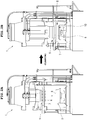
- the reference numeral 1 denotes an injection stretch blow molding machine.
- the injection stretch blow molding machine 1 is provided with three stations, which includes an injection molding unit 2, a stretch blow molding unit 3, and an ejection unit 4, on a lower base plate. Further included is a rotating plate unit 5 that is movable upward and downward in a vertical direction above the three stations.
- the aforementioned injection molding unit 2, stretch blow molding unit 3, and ejection unit 4 are disposed in the same circumference at intervals of a constant angle (120 degrees).
- a rotating plate unit 5 which has lip molds 6 each for forming an outer peripheral surface of a preform mouth portion and for transferring a preform on its bottom surface, is provided rotatably about a rotation axis passing through the center of the disposition of the stations so as to stop every time the rotating plate 7 turns at a constant rotation angle (120 degrees).
- the lip molds 6 are situated in positions corresponding to the injection molding unit 2, the stretch blow molding unit 3, and the ejection unit 4.
- a cavity mold 8 fixed in the position of the aforementioned injection molding unit 2, the lip mold 6, and a core mold 9 that is movable upward and downward in the injection molding unit 2 and is inserted into the cavity mold 8 through the lip mold 6 form an injection molding mold 10 in the injection molding unit 2, as shown in FIG. 2 .
- stretch blow molding unit 3 a pair of split molds i.e. blow molds 11 disposed in the stretch blow molding unit 3, as shown in FIG. 3 , and the lip mold 6 form a stretch blow mold 12.
- stretch blow molding is performed in the stretch blow molding unit 3, by stretching operation using a stretch rod 13 inserted into the blow mold 11 and blow air blow-in 14 from blow air supply unit.
- a molded product reception port 15 is formed under the lip mold 6 that is situated in the position corresponding to the ejection unit 4.
- a resin is fed from an injection device into the injection molding mold 10 formed by the lip mold 6 disposed in the injection molding unit 2, to mold a preform.
- the molded preform is transferred to the stretch blow molding unit 3 by an ascent movement and a circular movement of the lip mold 6 due to an ascent of the rotating plate unit 5 and a turn of the rotating plate 7 after opening the mold.
- the preform is molded into a container by stretch blowing.
- the transfer of the lip mold 6 causes the molded container to be transferred from the stretch blow molding unit 3 to the ejection unit 4.
- the container i.e., the molded product is sent out of the machine.
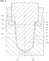
- FIG. 5 shows the injection molding mold 10 of the aforementioned injection molding unit 2, which is constituted of the lip mold 6, the cavity mold 8, and the core mold 9, as described above.
- the injection molding mold 10 is a mold for use in molding a preform for a container of the type of a PET bottle, the container body of which is large in diameter relative to the container mouth portion thereof in its final molded shape.
- the lip mold 6 includes a screw formation recessed portion 16 and a flange formation recessed portion 17.
- the lip mold 6, the cavity mold 8, and the core mold 9 of the injection molding mold 10 form a preform formation space 18 in an enclosed manner.
- the preform formation space 18 is formed from a preform mouth portion forming portion 19, a preform body forming portion 20 that is continuous with the preform mouth portion forming portion 19 and has a gap width that is uniform and wider than the gap width of the preform mouth portion forming portion 19, and a preform bottom forming portion 21 that is continuous with the preform body forming portion 20 and the bottom end of which functions as a gate for feeding a molten resin from the injection device into the preform formation space 18.
- the aforementioned core mold 9 is devised to prevent a collapse in the preform that has been molded in the aforementioned preform formation space 18, when opening the mold (removal of the molds).
- the core mold 9 is formed from a preform mouth portion inner surface forming portion 22, a preform body inner surface forming portion 23, and a preform bottom inner surface forming portion 24.
- the aforementioned preform mouth portion inner surface forming portion 22 is a portion corresponding to the aforementioned preform mouth portion forming portion 19.
- the preform body inner surface forming portion 23 is a portion corresponding to the aforementioned preform body forming portion 20.
- the preform bottom inner surface forming portion 24 is a portion corresponding to the aforementioned preform bottom forming portion 21.
- the core mold 9 includes a diameter enlarging portion 25 the diameter of which is gradually increased such that the degree of diameter enlargement is slightly larger than the degree of diameter enlargement of the preform body inner surface forming portion 23 (the degree of gradually increasing the diameter of the core mold upward of the core mold).
- the diameter enlarging portion 25 is provided between the preform body inner surface forming portion 23 and the preform mouth portion inner surface forming portion 22.
- the degree of diameter enlargement is slightly larger than the degree of diameter enlargement of the preform body inner surface forming portion 23 upward of the core mold.
- a core mold outer peripheral surface 26 of the diameter enlarging portion 25 is tapered so as to be inclined outward relative to the position of an upward extension line 28 along a core mold outer peripheral surface 27 of the preform body inner surface forming portion 23.
- the aforementioned core mold outer peripheral surface 26 is provided between the preform body inner surface forming portion 23 and the preform mouth portion inner surface forming portion 22, in particular, is continuous with a portion of the preform mouth portion inner surface forming portion 22 facing the lip mold 6.
- the upward extension line 28 along the core mold outer peripheral surface 26 is formed so as to intersect an upper end portion 19a of the aforementioned preform mouth portion forming portion 19 of the preform formation space 18.
- the diameter enlarging portion 25 of the core mold 9 is situated as follows in this embodiment.
- the diameter enlarging portion 25 is provided between a portion of the preform body inner surface forming portion 23 facing the cavity mold 8 and a portion of the preform mouth portion inner surface forming portion 22 facing the lip mold 6 through a height position 29 of a parting line between the cavity mold 8 and the lip mold 6.
- the resin is injected from the injection device into the aforementioned injection molding mold 10 structured in the injection molding unit 2 and is fed into the aforementioned preform formation space 18 of the injection molding mold 10, a preform is molded in which a surface layer that is in contact with the surrounding injection molding mold is cooled to have a low temperature and hardened into a skin layer, even though a middle layer of the charged resin has a high temperature.
- the preform is molded in the order of several seconds. Upon opening the mold, the preform is transferred to the next stretch blow molding unit 3 with the lip mold 6, to obtain the preform to be subject to stretch blowing.
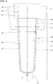
- FIG. 6 shows a preform 30 molded with the aforementioned injection molding mold 10.
- the preform 30 having a bottom includes a preform mouth portion 31, a preform body 32 continuous with the preform mouth portion 31, and a preform bottom 33 continuous with the preform body 32.
- a skin layer 34 of a surface layer has a lower temperature than a middle layer 35.
- the preform body 32 and the preform bottom 33 can be expanded and deformed from the inside of the preform to the outside of the preform, to obtain the shape of a PET bottle as a final shape by stretch blowing in the stretch blow molding unit 3.
- a screw portion 36 and a flange portion 37 are integrally formed in the outer peripheral surface of the preform mouth portion 31 in accordance with the screw formation recessed portion 16 and the flange formation recessed portion 17 in the aforementioned lip mold 6, respectively.
- the skin layer 34 inside the aforementioned preform 30 has a portion corresponding to the diameter enlarging portion 25 of the aforementioned core mold 9.
- the skin layer 34 extending from an inner surface of the preform body 32 to an inner surface of the preform mouth portion 31 is a portion formed continuously from the preform body forming portion 20 on the side of the core mold 9 to the preform mouth portion forming portion 19 on the side of the core mold 9 in the aforementioned preform formation space 18 when molding a preform, and therefore, this portion is molded while being in contact with the core mold outer peripheral surface 26 of the diameter enlarging portion 25 of the core mold 9.
- the skin layer 34 that is molded while being in contact with the core mold outer peripheral surface 26 of the diameter enlarging portion 25 has a tapered shape opened upward so as to be inclined outward relative to an upward extension line 38 of the skin layer 34 in the inner surface of the preform body 32.
- the skin layer 34 that is molded while being in contact with the core mold outer peripheral surface 26 of the diameter enlarging portion 25 serves as a stress dispersion surface portion 39.
- the aforementioned stress dispersion surface portion 39 made of the skin layer 34 has the function of preventing a collapse in the shape of the preform when opening the mold.
- the stress dispersion surface portion 39 is a portion to prevent upward movement of the resin charged in the aforementioned preform body forming portion in association with an ascent of the core mold 9 due to the mold opening.
- the preform 30 is molded in a state that the skin layer 34 having a lower temperature than the middle layer 35 has a higher stiffness than the flowable resin of the middle layer 35.
- the aforementioned stress dispersion surface portion 39 is a portion having a high stiffness in the inner surface of the preform 30.
- the skin layer 34 also has a high stiffness inside the preform mouth portion 31 and the preform body 32, which are continuous with the stress dispersion surface portion 39.
- the core mold 9 is caused to ascend by mold opening, when the above-described preform 30 is obtained.
- the preform body inner surface forming portion 23 of the core mold 9 ascends, the preform body 32 of the preform 30 almost ascends in a following manner, and an ascending pressure is transferred from the preform body 32 to the aforementioned stress dispersion surface portion 39.
- the core mold outer peripheral surface 26 of the diameter enlarging portion 25 is formed widely in the vertical direction of the core mold, and the extension line 28 of the core mold outer peripheral surface 26 intersects the upper end portion 19a of the preform mouth portion forming portion 19.
- the aforementioned stress dispersion surface portion 39 is formed widely in the vertical direction of the preform 30, and the stress dispersion surface portion 39 is inclined such that an upward extension line 40 along the stress dispersion surface portion 39 intersects an upper end surface 41 of the preform mouth portion 31.
- the stress dispersion surface portion 39 When the aforementioned ascending pressure is transferred from the preform body 32 to the stress dispersion surface portion 39, a stress occurs in the stress dispersion surface portion 39 as a drag, but the stress is dispersed in the wide stress dispersion surface portion 39 without being concentrated locally. Furthermore, since the stress dispersion surface portion 39 is inclined extremely shallowly relative to a following ascending direction of the preform body (ascending direction of the core mold), the stress is properly transferred to the skin layer 34 in the inner surface of the preform mouth portion 31. Since the preform mouth portion 31 itself is thin, the ratio of the skin layer 34 to the thickness of the preform mouth portion 31 is high (the thickness of the skin layer is thick in a thickness direction of the preform mouth portion). As a result, the entire preform mouth portion 31 has an increased stiffness, and certainly supports the pressure from the stress dispersion surface portion 39. Note that, in FIG. 6 , arrows indicate the directions of the pressure in the skin layer 34.
- the injection stretch blow molding machine 1 To mold a container, after the injection stretch blow molding machine 1 molds the preform 30, as described above, the injection stretch blow molding machine 1 performs stretch blow molding at the stretch blow molding unit 3, and sends a PET bottle type container obtained by the stretch blow molding out of the machine at the ejection unit 4.
- FIG. 7 shows a conventional preform 30 for the sake of comparison. Note that the same reference numerals indicate the same components for ease of explanation.
- the conventional preform 30 molded in an injection molding unit of an injection stretch blow molding machine had a step portion 42 in an inner surface of a preform body 32 on the side of a preform mouth portion 31, in order to absorb the difference in thickness between the preform mouth portion 31 and the preform body 32.
- the entire step portion 42 was formed in an area corresponding to a cavity mold 8, and an inner peripheral surface of the step portion 42 was inclined such that an upward extension line along the inner peripheral surface intersected a base end of the preform mouth portion 31.
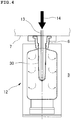
- FIG. 8 shows an example of the contrivance for the shape of the preform formation space, when molding a preform of the present invention, for ease in charging the resin into the preform formation space of the injection molding mold.
- a cylindrical portion 43 the diameter of which is reduced downward is provided between the aforementioned preform body forming portion 20 and the aforementioned preform bottom forming portion 21.
- the cylindrical portion 43 is tapered such that a downward tangent 44 of the cylindrical portion 43 in the vertical direction is inclined to a center line 18a of the preform formation space, with respect to a downward extension line 45 of the preform body forming portion 20.
- the resin when the resin is fed from the gate, the resin moves with a reduced resistance from the preform bottom forming portion 21 to the preform body forming portion 20, thus facilitating charging the resin in a smoother manner.
- This provides a favorable effect in acceleration of the ascent timing of the core mold.
- FIG. 9 shows an example of molding a preform to obtain a jar as a final molded product.
- the jar itself as the final molded product is a jar the mouth portion of which is covered with a lid.
- a fit projection molding recessed portion 46 is provided in an outer peripheral surface of the preform mouth portion forming portion.
- the aforementioned injection stretch blow molding machine 1 performs the stages of preform molding and stretch blow molding, and then a final molded product is sent out of the machine to obtain a jar.
- the degree of enlargement of the diameter of the core mold is slightly larger than the degree of diameter enlargement of a preform body inner surface forming portion 23 in an upward direction of the core mold.
- a core mold outer peripheral surface 26 of the diameter enlarging portion 25 is tapered so as to be inclined outward relative to the position of an upward extension line 28 along a core mold outer peripheral surface 27 of the preform body inner surface forming portion 23.
- the above-described core mold outer peripheral surface 26 is continuous with an area facing the lip mold 6 between the preform body inner surface forming portion 23 and a preform mouth portion inner surface forming portion 22.
- An upward extension line 28 along the core mold outer peripheral surface 26 intersects an upper end portion 19a of a preform mouth portion forming portion 19.
- the diameter enlarging portion 25 is provided so as to extend between a portion of the preform body inner surface forming portion 23 facing the cavity mold 8 and a portion of the preform mouth portion inner surface forming portion 22 facing the lip mold 6 through the height position 29 of the parting line between the cavity mold 8 and the lip mold 6. This disposition makes the tapered core mold outer peripheral surface 26 of the diameter enlarging portion 25 formed widely in the vertical direction of the core mold.
- FIG. 10 shows a preform 30 molded with an injection molding mold 10 according to the above-described other embodiment.
- a skin layer 34 of a surface layer has a lower temperature than a middle layer 35.
- a preform body 32 and a preform bottom 33 can be expanded and deformed from the inside of the preform to the outside of the preform, to obtain the shape of a jar as a final shape by stretch blowing in the stretch blow molding unit 3.
- the skin layer 34 extending from an inner surface of the preform body 32 to an inner surface of a preform mouth portion 31 is a portion formed continuously from the preform body forming portion 20 on the side of the core mold 9 to the preform mouth portion forming portion 19 on the side of the core mold 9 in the preform formation space 18 when molding a preform, and therefore, this portion is molded while being in contact with the core mold outer peripheral surface 26 of the diameter enlarging portion 25 of the core mold 9.
- the skin layer 34 that is molded while being in contact with the core mold outer peripheral surface 26 of the diameter enlarging portion 25 has a tapered shape opened upward so as to be inclined outward relative to an upward extension line 38 of the skin layer 34 in the inner surface of the preform body 32.
- the skin layer 34 that is molded with the core mold outer peripheral surface 26 serves as a stress dispersion surface portion 39.
- the aforementioned stress dispersion surface portion 39 in the inner surface of the preform 30 has an increased stiffness, and the skin layer 34 inside the preform mouth portion 31 and the skin layer 34 inside the preform body 32 also have an increased stiffness.
- the core mold outer peripheral surface 26 of the diameter enlarging portion 25 is formed widely in the vertical direction of the core mold, and the extension line 28 of the core mold outer peripheral surface 26 intersects the upper end portion 19a of the preform mouth portion forming portion 19.
- the stress dispersion surface portion 39 is formed widely in the vertical direction of the preform 30, and the stress dispersion surface portion 39 is inclined such that an upward extension line 40 along the stress dispersion surface portion 39 intersects an upper end surface 41 of the preform mouth portion 31.
- the stress dispersion surface portion 39 When the ascending pressure is transferred from the preform body 32 to the stress dispersion surface portion 39, a stress occurs in the stress dispersion surface portion 39 as a drag, but the stress is dispersed in the wide stress dispersion surface portion 39 without being concentrated locally. Furthermore, since the stress dispersion surface portion 39 is inclined extremely shallowly relative to a following ascending direction of the preform body, the stress is properly transferred to the skin layer 34 in the inner surface of the preform mouth portion 31. Since the preform mouth portion 31 itself is thin, the ratio of the skin layer 34 to the thickness of the preform mouth portion 31 is high (the thickness of the skin layer is thick in a thickness direction of the preform mouth portion). Just as with the above-described embodiment, the pressure from the stress dispersion surface portion 39 is certainly supported. In FIG. 10 , arrows indicate the directions of the pressure in the skin layer 34.
- the preform is molded in a molten state having very little crystallization in the injection molding unit of the injection stretch blow molding machine having the aforementioned structure according to the embodiments.
- a shaped portion of the preform that is provided to mold a container is thinned and stretched, thus allowing formation of a molded product having an extremely small number of crystallized portions owing to rapid cooling.
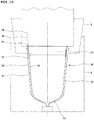
- a preform having a thickness of 7.5 mm was formed of a polyethylene terephthalate resin, and thus a container A having the shape of FIG. 11 was molded.
- a container body is elliptical in plan having a maximum width of a wide portion of 50 mm.
- a container height is 95 mm.
- the thickness of a shaped portion of the container body and the like is 1.6 to 2.1 mm. The transparency of the body of the obtained container was measured.
- Haze is obtained as the transparency.
- a test method for measuring a haze value is as follows.
- the injection cooling time (total time) is 42 seconds.
Landscapes
- Engineering & Computer Science (AREA)
- Mechanical Engineering (AREA)
- Manufacturing & Machinery (AREA)
- Physics & Mathematics (AREA)
- Thermal Sciences (AREA)
- Blow-Moulding Or Thermoforming Of Plastics Or The Like (AREA)
- Moulds For Moulding Plastics Or The Like (AREA)
- Injection Moulding Of Plastics Or The Like (AREA)
Applications Claiming Priority (4)
| Application Number | Priority Date | Filing Date | Title |
|---|---|---|---|
| JP2015242217 | 2015-12-11 | ||
| JP2016105539A JP6647144B2 (ja) | 2015-12-11 | 2016-05-26 | 射出延伸ブロー成形機の射出成形型とプリフォームの成形方法とプリフォーム、及び容器の成形方法と容器 |
| PCT/JP2016/002855 WO2017098673A1 (ja) | 2015-12-11 | 2016-06-13 | 射出延伸ブロー成形機の射出成形型とプリフォームの成形方法とプリフォーム、及び容器の成形方法と容器 |
| EP16872575.2A EP3287257B1 (en) | 2015-12-11 | 2016-06-13 | Injection mold for injection stretch blow molding machine, method for molding preform, preform and method for molding container |
Related Parent Applications (2)
| Application Number | Title | Priority Date | Filing Date |
|---|---|---|---|
| EP16872575.2A Division-Into EP3287257B1 (en) | 2015-12-11 | 2016-06-13 | Injection mold for injection stretch blow molding machine, method for molding preform, preform and method for molding container |
| EP16872575.2A Division EP3287257B1 (en) | 2015-12-11 | 2016-06-13 | Injection mold for injection stretch blow molding machine, method for molding preform, preform and method for molding container |
Publications (2)
| Publication Number | Publication Date |
|---|---|
| EP3747623A1 EP3747623A1 (en) | 2020-12-09 |
| EP3747623B1 true EP3747623B1 (en) | 2021-11-17 |
Family
ID=59079143
Family Applications (2)
| Application Number | Title | Priority Date | Filing Date |
|---|---|---|---|
| EP20020298.4A Active EP3747623B1 (en) | 2015-12-11 | 2016-06-13 | Injection molding mold for an injection molding unit of an injection stretch blow molding machine, method for molding a preform, and a method for molding a container |
| EP16872575.2A Active EP3287257B1 (en) | 2015-12-11 | 2016-06-13 | Injection mold for injection stretch blow molding machine, method for molding preform, preform and method for molding container |
Family Applications After (1)
| Application Number | Title | Priority Date | Filing Date |
|---|---|---|---|
| EP16872575.2A Active EP3287257B1 (en) | 2015-12-11 | 2016-06-13 | Injection mold for injection stretch blow molding machine, method for molding preform, preform and method for molding container |
Country Status (10)
| Country | Link |
|---|---|
| US (1) | US10953588B2 (zh) |
| EP (2) | EP3747623B1 (zh) |
| JP (2) | JP6647144B2 (zh) |
| KR (1) | KR102264966B1 (zh) |
| CN (1) | CN107530948B (zh) |
| CA (1) | CA2981967C (zh) |
| ES (2) | ES2828823T3 (zh) |
| HK (1) | HK1247594A1 (zh) |
| TW (2) | TWI697397B (zh) |
| WO (1) | WO2017098673A1 (zh) |
Families Citing this family (20)
| Publication number | Priority date | Publication date | Assignee | Title |
|---|---|---|---|---|
| US11072102B2 (en) * | 2017-04-04 | 2021-07-27 | Imflux, Inc. | In-mold non-time dependent determination of injection molded part ejection readiness |
| EP3642001B1 (en) | 2017-06-21 | 2022-12-14 | iMFLUX Inc. | Injection molding of crosslinking polymers using strain data |
| EP4338930A2 (en) | 2017-10-19 | 2024-03-20 | Nissei ASB Machine Co., Ltd. | Method for producing resin vessel made of resin, mould unit and moulding apparatus |
| JP6840393B2 (ja) * | 2018-04-19 | 2021-03-10 | 株式会社青木固研究所 | 射出延伸ブロー成形機と中空成形体の製造方法 |
| CN113302033B (zh) | 2018-12-28 | 2024-03-26 | 日精Asb机械株式会社 | 吹塑成型装置、吹塑成型方法及模具单元 |
| CN113613860B (zh) | 2019-01-31 | 2023-12-26 | 日精Asb机械株式会社 | 树脂容器制造设备、树脂容器制造方法及温度调节方法 |
| KR102643807B1 (ko) | 2019-01-31 | 2024-03-05 | 닛세이 에이. 에스. 비 기카이 가부시키가이샤 | 수지제 용기의 제조장치 및 제조방법 |
| KR102646476B1 (ko) | 2019-01-31 | 2024-03-11 | 닛세이 에이. 에스. 비 기카이 가부시키가이샤 | 수지제 용기의 제조장치 및 제조방법 |
| CN113631347B (zh) | 2019-01-31 | 2024-04-02 | 日精Asb机械株式会社 | 预制件的温度调节装置和温度调节方法以及树脂成型容器的制造装置和制造方法 |
| WO2020166642A1 (ja) * | 2019-02-13 | 2020-08-20 | 日精エー・エス・ビー機械株式会社 | 射出ブロー成形装置 |
| US11701811B2 (en) | 2019-03-20 | 2023-07-18 | Nissei Asb Machine Co., Ltd. | Method for manufacturing resin container and blow molding method |
| JP7445643B2 (ja) | 2019-03-26 | 2024-03-07 | 日精エー・エス・ビー機械株式会社 | 射出成形用金型、樹脂製容器製造装置、およびプラグユニット |
| WO2021060497A1 (ja) * | 2019-09-27 | 2021-04-01 | 日精エー・エス・ビー機械株式会社 | 樹脂製容器の製造方法および樹脂製容器の製造装置 |
| WO2021221024A1 (ja) * | 2020-04-27 | 2021-11-04 | 日精エー・エス・ビー機械株式会社 | 樹脂製広口容器の製造方法、製造装置および樹脂製広口容器 |
| JP6777960B1 (ja) * | 2020-06-18 | 2020-10-28 | 株式会社青木固研究所 | 射出成形型とプリフォーム成形方法、及び中空体の製造方法 |
| JPWO2022107851A1 (zh) | 2020-11-18 | 2022-05-27 | ||
| CN112793104A (zh) * | 2020-12-24 | 2021-05-14 | 宜都鑫华光电有限公司 | 一种树脂光学镜片注塑用温控设备 |
| JP2022180954A (ja) | 2021-05-25 | 2022-12-07 | 株式会社青木固研究所 | 射出成形金型と射出延伸ブロー成形機、及び中空成形体の製造方法 |
| JP7031915B1 (ja) * | 2021-07-13 | 2022-03-08 | 株式会社青木固研究所 | 中空成形体の製造方法と射出延伸ブロー成形機 |
| KR20230068611A (ko) | 2021-11-11 | 2023-05-18 | (주)지웰 | 페트병 프리폼 사출성형 금형장치 |
Family Cites Families (18)
| Publication number | Priority date | Publication date | Assignee | Title |
|---|---|---|---|---|
| JPS5186770U (zh) * | 1974-12-28 | 1976-07-12 | ||
| JPS55146718A (en) * | 1979-05-01 | 1980-11-15 | Yoshino Kogyosho Co Ltd | Intermediate blank made of synthetic resin for molding biaxially spread bottle |
| AU640997B2 (en) * | 1990-03-30 | 1993-09-09 | A. K. Technical Laboratory, Inc. | Injection orientation blow molding method |
| JPH0699482A (ja) * | 1992-09-18 | 1994-04-12 | Dainippon Printing Co Ltd | 予備成形体の温度調節方法及び装置 |
| JP3290011B2 (ja) | 1993-10-22 | 2002-06-10 | 株式会社青木固研究所 | 射出延伸吹込成形におけるプリフォーム成形方法 |
| US5620650A (en) | 1993-10-22 | 1997-04-15 | A.K. Technical Laboratory Inc. | Method for injection stretch blow molding of polyethylene |
| JPH1076566A (ja) * | 1996-09-05 | 1998-03-24 | Aokiko Kenkyusho:Kk | プリフォームにおけるネック部の内ねじ成形方法 |
| JP3748487B2 (ja) * | 1997-12-26 | 2006-02-22 | 株式会社青木固研究所 | 射出延伸ブロー成形方法 |
| JPH11208630A (ja) * | 1998-01-30 | 1999-08-03 | Aokiko Kenkyusho:Kk | ストレッチブローボトルの首部構造 |
| JP2000043130A (ja) * | 1998-07-31 | 2000-02-15 | Aokikatashi Kenkyusho:Kk | 射出延伸ブロー成形方法 |
| JP2003170487A (ja) * | 2001-09-25 | 2003-06-17 | Frontier:Kk | コップ状容器のプリフォーム |
| JP2004268570A (ja) * | 2003-02-19 | 2004-09-30 | Frontier:Kk | プラスチック製カップ状容器およびその一次成形品 |
| PL207809B1 (pl) * | 2003-11-20 | 2011-02-28 | Invento Społka Z Ograniczoną Odpowiedzialnością | Preforma pojemnika z tworzywa sztucznego, zwłaszcza do środków spożywczych |
| US20060065992A1 (en) * | 2004-04-16 | 2006-03-30 | Hutchinson Gerald A | Mono and multi-layer articles and compression methods of making the same |
| JP4739933B2 (ja) * | 2005-11-30 | 2011-08-03 | 株式会社青木固研究所 | 射出延伸ブロー成形機 |
| JP4837442B2 (ja) | 2006-05-30 | 2011-12-14 | 株式会社青木固研究所 | 射出延伸ブロー成形機 |
| JP5286169B2 (ja) * | 2009-06-19 | 2013-09-11 | 株式会社青木固研究所 | 延伸ブローボトルのプリフォーム |
| JP5582206B2 (ja) * | 2013-02-05 | 2014-09-03 | 大日本印刷株式会社 | プラスチックボトル成形用プリフォーム |
-
2016
- 2016-05-26 JP JP2016105539A patent/JP6647144B2/ja active Active
- 2016-06-13 WO PCT/JP2016/002855 patent/WO2017098673A1/ja active Application Filing
- 2016-06-13 KR KR1020177034270A patent/KR102264966B1/ko active IP Right Grant
- 2016-06-13 ES ES16872575T patent/ES2828823T3/es active Active
- 2016-06-13 CN CN201680027426.3A patent/CN107530948B/zh active Active
- 2016-06-13 EP EP20020298.4A patent/EP3747623B1/en active Active
- 2016-06-13 ES ES20020298T patent/ES2904488T3/es active Active
- 2016-06-13 US US15/564,583 patent/US10953588B2/en active Active
- 2016-06-13 CA CA2981967A patent/CA2981967C/en active Active
- 2016-06-13 EP EP16872575.2A patent/EP3287257B1/en active Active
- 2016-11-30 TW TW105139495A patent/TWI697397B/zh active
- 2016-11-30 TW TW109117021A patent/TWI720895B/zh active
-
2018
- 2018-05-31 HK HK18107113.7A patent/HK1247594A1/zh unknown
-
2020
- 2020-01-14 JP JP2020003370A patent/JP6679060B2/ja active Active
Also Published As
| Publication number | Publication date |
|---|---|
| EP3287257A1 (en) | 2018-02-28 |
| US20180079127A1 (en) | 2018-03-22 |
| EP3287257A4 (en) | 2018-11-14 |
| EP3287257B1 (en) | 2020-08-05 |
| JP6647144B2 (ja) | 2020-02-14 |
| TW201720623A (zh) | 2017-06-16 |
| KR20180091710A (ko) | 2018-08-16 |
| CN107530948B (zh) | 2021-10-19 |
| KR102264966B1 (ko) | 2021-06-14 |
| TWI720895B (zh) | 2021-03-01 |
| JP2020055319A (ja) | 2020-04-09 |
| TW202039215A (zh) | 2020-11-01 |
| TWI697397B (zh) | 2020-07-01 |
| JP6679060B2 (ja) | 2020-04-15 |
| CN107530948A (zh) | 2018-01-02 |
| US10953588B2 (en) | 2021-03-23 |
| HK1247594A1 (zh) | 2018-09-28 |
| EP3747623A1 (en) | 2020-12-09 |
| WO2017098673A1 (ja) | 2017-06-15 |
| CA2981967C (en) | 2022-04-12 |
| ES2828823T3 (es) | 2021-05-27 |
| JP2017109472A (ja) | 2017-06-22 |
| CA2981967A1 (en) | 2017-06-15 |
| ES2904488T3 (es) | 2022-04-05 |
Similar Documents
| Publication | Publication Date | Title |
|---|---|---|
| EP3747623B1 (en) | Injection molding mold for an injection molding unit of an injection stretch blow molding machine, method for molding a preform, and a method for molding a container | |
| KR102398863B1 (ko) | 수지제 용기의 제조방법, 금형 유닛 및 성형기 | |
| US6349838B1 (en) | Plastic bottle and method of producing the same | |
| US5840350A (en) | Modified plastic bottle injection blow-molding apparatus and method | |
| MX2015002824A (es) | Preforma para la produccion de recipientes de plastico en un proceso para moldeo por soplado con estiramiento. | |
| US20190061222A1 (en) | Mold unit, blow molding apparatus and blow molding method | |
| CN110776245A (zh) | 一种行列机小口瓶压吹模具 | |
| EP2716430A1 (en) | Preform, synthetic-resin container with hanging attachment, and method for forming container with hanging attachment | |
| EP3991937A1 (en) | Apparatus for producing resin molded article, method for producing resin molded article, and resin molded article | |
| CN115503216B (zh) | 一种医用药液定量分装的塑料包装成型方法 | |
| EP3530430A1 (en) | Blow molding device and method for manufacturing synthetic resin container using same | |
| WO1992003276A1 (en) | Blow molding of polyethylene terephthalate | |
| CN218966114U (zh) | 一种分体式吹塑口模 | |
| CN112752642B (zh) | 容器输送单元 | |
| CN116373269A (zh) | 一种分体式吹塑口模 | |
| WO2007136720A2 (en) | In-mold finished neck on a continuous extrusion blow molder | |
| AU2004202706A1 (en) | Accumulating extrusion blow moulding process |
Legal Events
| Date | Code | Title | Description |
|---|---|---|---|
| PUAI | Public reference made under article 153(3) epc to a published international application that has entered the european phase |
Free format text: ORIGINAL CODE: 0009012 |
|
| STAA | Information on the status of an ep patent application or granted ep patent |
Free format text: STATUS: THE APPLICATION HAS BEEN PUBLISHED |
|
| AC | Divisional application: reference to earlier application |
Ref document number: 3287257 Country of ref document: EP Kind code of ref document: P |
|
| AK | Designated contracting states |
Kind code of ref document: A1 Designated state(s): AL AT BE BG CH CY CZ DE DK EE ES FI FR GB GR HR HU IE IS IT LI LT LU LV MC MK MT NL NO PL PT RO RS SE SI SK SM TR |
|
| STAA | Information on the status of an ep patent application or granted ep patent |
Free format text: STATUS: REQUEST FOR EXAMINATION WAS MADE |
|
| 17P | Request for examination filed |
Effective date: 20210225 |
|
| RBV | Designated contracting states (corrected) |
Designated state(s): AL AT BE BG CH CY CZ DE DK EE ES FI FR GB GR HR HU IE IS IT LI LT LU LV MC MK MT NL NO PL PT RO RS SE SI SK SM TR |
|
| GRAP | Despatch of communication of intention to grant a patent |
Free format text: ORIGINAL CODE: EPIDOSNIGR1 |
|
| STAA | Information on the status of an ep patent application or granted ep patent |
Free format text: STATUS: GRANT OF PATENT IS INTENDED |
|
| RIC1 | Information provided on ipc code assigned before grant |
Ipc: B29B 11/08 20060101ALN20210518BHEP Ipc: B29L 31/00 20060101ALN20210518BHEP Ipc: B29K 105/00 20060101ALN20210518BHEP Ipc: B29C 49/06 20060101ALI20210518BHEP Ipc: B29C 49/12 20060101ALI20210518BHEP Ipc: B29C 45/78 20060101ALI20210518BHEP Ipc: B29C 49/48 20060101ALI20210518BHEP Ipc: B29C 49/64 20060101ALI20210518BHEP Ipc: B29C 45/26 20060101AFI20210518BHEP |
|
| RIC1 | Information provided on ipc code assigned before grant |
Ipc: B29B 11/08 20060101ALN20210525BHEP Ipc: B29L 31/00 20060101ALN20210525BHEP Ipc: B29K 105/00 20060101ALN20210525BHEP Ipc: B29C 49/06 20060101ALI20210525BHEP Ipc: B29C 49/12 20060101ALI20210525BHEP Ipc: B29C 45/78 20060101ALI20210525BHEP Ipc: B29C 49/48 20060101ALI20210525BHEP Ipc: B29C 49/64 20060101ALI20210525BHEP Ipc: B29C 45/26 20060101AFI20210525BHEP |
|
| RIC1 | Information provided on ipc code assigned before grant |
Ipc: B29B 11/08 20060101ALN20210601BHEP Ipc: B29L 31/00 20060101ALN20210601BHEP Ipc: B29K 105/00 20060101ALN20210601BHEP Ipc: B29C 49/06 20060101ALI20210601BHEP Ipc: B29C 49/12 20060101ALI20210601BHEP Ipc: B29C 45/78 20060101ALI20210601BHEP Ipc: B29C 49/48 20060101ALI20210601BHEP Ipc: B29C 49/64 20060101ALI20210601BHEP Ipc: B29C 45/26 20060101AFI20210601BHEP |
|
| INTG | Intention to grant announced |
Effective date: 20210617 |
|
| GRAJ | Information related to disapproval of communication of intention to grant by the applicant or resumption of examination proceedings by the epo deleted |
Free format text: ORIGINAL CODE: EPIDOSDIGR1 |
|
| STAA | Information on the status of an ep patent application or granted ep patent |
Free format text: STATUS: REQUEST FOR EXAMINATION WAS MADE |
|
| REG | Reference to a national code |
Ref country code: DE Ref legal event code: R079 Ref document number: 602016066489 Country of ref document: DE Free format text: PREVIOUS MAIN CLASS: B29C0049480000 Ipc: B29C0045260000 |
|
| GRAS | Grant fee paid |
Free format text: ORIGINAL CODE: EPIDOSNIGR3 |
|
| STAA | Information on the status of an ep patent application or granted ep patent |
Free format text: STATUS: GRANT OF PATENT IS INTENDED |
|
| GRAP | Despatch of communication of intention to grant a patent |
Free format text: ORIGINAL CODE: EPIDOSNIGR1 |
|
| INTC | Intention to grant announced (deleted) | ||
| RIC1 | Information provided on ipc code assigned before grant |
Ipc: B29B 11/08 20060101ALN20210907BHEP Ipc: B29L 31/00 20060101ALN20210907BHEP Ipc: B29K 105/00 20060101ALN20210907BHEP Ipc: B29C 49/06 20060101ALI20210907BHEP Ipc: B29C 49/12 20060101ALI20210907BHEP Ipc: B29C 45/78 20060101ALI20210907BHEP Ipc: B29C 49/48 20060101ALI20210907BHEP Ipc: B29C 49/64 20060101ALI20210907BHEP Ipc: B29C 45/26 20060101AFI20210907BHEP |
|
| GRAA | (expected) grant |
Free format text: ORIGINAL CODE: 0009210 |
|
| STAA | Information on the status of an ep patent application or granted ep patent |
Free format text: STATUS: THE PATENT HAS BEEN GRANTED |
|
| INTG | Intention to grant announced |
Effective date: 20211001 |
|
| RIC1 | Information provided on ipc code assigned before grant |
Ipc: B29B 11/08 20060101ALN20210920BHEP Ipc: B29L 31/00 20060101ALN20210920BHEP Ipc: B29K 105/00 20060101ALN20210920BHEP Ipc: B29C 49/06 20060101ALI20210920BHEP Ipc: B29C 49/12 20060101ALI20210920BHEP Ipc: B29C 45/78 20060101ALI20210920BHEP Ipc: B29C 49/48 20060101ALI20210920BHEP Ipc: B29C 49/64 20060101ALI20210920BHEP Ipc: B29C 45/26 20060101AFI20210920BHEP |
|
| AC | Divisional application: reference to earlier application |
Ref document number: 3287257 Country of ref document: EP Kind code of ref document: P |
|
| AK | Designated contracting states |
Kind code of ref document: B1 Designated state(s): AL AT BE BG CH CY CZ DE DK EE ES FI FR GB GR HR HU IE IS IT LI LT LU LV MC MK MT NL NO PL PT RO RS SE SI SK SM TR |
|
| REG | Reference to a national code |
Ref country code: GB Ref legal event code: FG4D |
|
| REG | Reference to a national code |
Ref country code: DE Ref legal event code: R096 Ref document number: 602016066489 Country of ref document: DE |
|
| REG | Reference to a national code |
Ref country code: IE Ref legal event code: FG4D |
|
| REG | Reference to a national code |
Ref country code: AT Ref legal event code: REF Ref document number: 1447696 Country of ref document: AT Kind code of ref document: T Effective date: 20211215 |
|
| REG | Reference to a national code |
Ref country code: LT Ref legal event code: MG9D |
|
| REG | Reference to a national code |
Ref country code: NL Ref legal event code: MP Effective date: 20211117 |
|
| REG | Reference to a national code |
Ref country code: ES Ref legal event code: FG2A Ref document number: 2904488 Country of ref document: ES Kind code of ref document: T3 Effective date: 20220405 |
|
| REG | Reference to a national code |
Ref country code: AT Ref legal event code: MK05 Ref document number: 1447696 Country of ref document: AT Kind code of ref document: T Effective date: 20211117 |
|
| PG25 | Lapsed in a contracting state [announced via postgrant information from national office to epo] |
Ref country code: RS Free format text: LAPSE BECAUSE OF FAILURE TO SUBMIT A TRANSLATION OF THE DESCRIPTION OR TO PAY THE FEE WITHIN THE PRESCRIBED TIME-LIMIT Effective date: 20211117 Ref country code: LT Free format text: LAPSE BECAUSE OF FAILURE TO SUBMIT A TRANSLATION OF THE DESCRIPTION OR TO PAY THE FEE WITHIN THE PRESCRIBED TIME-LIMIT Effective date: 20211117 Ref country code: FI Free format text: LAPSE BECAUSE OF FAILURE TO SUBMIT A TRANSLATION OF THE DESCRIPTION OR TO PAY THE FEE WITHIN THE PRESCRIBED TIME-LIMIT Effective date: 20211117 Ref country code: BG Free format text: LAPSE BECAUSE OF FAILURE TO SUBMIT A TRANSLATION OF THE DESCRIPTION OR TO PAY THE FEE WITHIN THE PRESCRIBED TIME-LIMIT Effective date: 20220217 Ref country code: AT Free format text: LAPSE BECAUSE OF FAILURE TO SUBMIT A TRANSLATION OF THE DESCRIPTION OR TO PAY THE FEE WITHIN THE PRESCRIBED TIME-LIMIT Effective date: 20211117 |
|
| PG25 | Lapsed in a contracting state [announced via postgrant information from national office to epo] |
Ref country code: IS Free format text: LAPSE BECAUSE OF FAILURE TO SUBMIT A TRANSLATION OF THE DESCRIPTION OR TO PAY THE FEE WITHIN THE PRESCRIBED TIME-LIMIT Effective date: 20220317 Ref country code: SE Free format text: LAPSE BECAUSE OF FAILURE TO SUBMIT A TRANSLATION OF THE DESCRIPTION OR TO PAY THE FEE WITHIN THE PRESCRIBED TIME-LIMIT Effective date: 20211117 Ref country code: PT Free format text: LAPSE BECAUSE OF FAILURE TO SUBMIT A TRANSLATION OF THE DESCRIPTION OR TO PAY THE FEE WITHIN THE PRESCRIBED TIME-LIMIT Effective date: 20220317 Ref country code: PL Free format text: LAPSE BECAUSE OF FAILURE TO SUBMIT A TRANSLATION OF THE DESCRIPTION OR TO PAY THE FEE WITHIN THE PRESCRIBED TIME-LIMIT Effective date: 20211117 Ref country code: NO Free format text: LAPSE BECAUSE OF FAILURE TO SUBMIT A TRANSLATION OF THE DESCRIPTION OR TO PAY THE FEE WITHIN THE PRESCRIBED TIME-LIMIT Effective date: 20220217 Ref country code: NL Free format text: LAPSE BECAUSE OF FAILURE TO SUBMIT A TRANSLATION OF THE DESCRIPTION OR TO PAY THE FEE WITHIN THE PRESCRIBED TIME-LIMIT Effective date: 20211117 Ref country code: LV Free format text: LAPSE BECAUSE OF FAILURE TO SUBMIT A TRANSLATION OF THE DESCRIPTION OR TO PAY THE FEE WITHIN THE PRESCRIBED TIME-LIMIT Effective date: 20211117 Ref country code: HR Free format text: LAPSE BECAUSE OF FAILURE TO SUBMIT A TRANSLATION OF THE DESCRIPTION OR TO PAY THE FEE WITHIN THE PRESCRIBED TIME-LIMIT Effective date: 20211117 Ref country code: GR Free format text: LAPSE BECAUSE OF FAILURE TO SUBMIT A TRANSLATION OF THE DESCRIPTION OR TO PAY THE FEE WITHIN THE PRESCRIBED TIME-LIMIT Effective date: 20220218 |
|
| PG25 | Lapsed in a contracting state [announced via postgrant information from national office to epo] |
Ref country code: SM Free format text: LAPSE BECAUSE OF FAILURE TO SUBMIT A TRANSLATION OF THE DESCRIPTION OR TO PAY THE FEE WITHIN THE PRESCRIBED TIME-LIMIT Effective date: 20211117 Ref country code: SK Free format text: LAPSE BECAUSE OF FAILURE TO SUBMIT A TRANSLATION OF THE DESCRIPTION OR TO PAY THE FEE WITHIN THE PRESCRIBED TIME-LIMIT Effective date: 20211117 Ref country code: RO Free format text: LAPSE BECAUSE OF FAILURE TO SUBMIT A TRANSLATION OF THE DESCRIPTION OR TO PAY THE FEE WITHIN THE PRESCRIBED TIME-LIMIT Effective date: 20211117 Ref country code: EE Free format text: LAPSE BECAUSE OF FAILURE TO SUBMIT A TRANSLATION OF THE DESCRIPTION OR TO PAY THE FEE WITHIN THE PRESCRIBED TIME-LIMIT Effective date: 20211117 Ref country code: DK Free format text: LAPSE BECAUSE OF FAILURE TO SUBMIT A TRANSLATION OF THE DESCRIPTION OR TO PAY THE FEE WITHIN THE PRESCRIBED TIME-LIMIT Effective date: 20211117 Ref country code: CZ Free format text: LAPSE BECAUSE OF FAILURE TO SUBMIT A TRANSLATION OF THE DESCRIPTION OR TO PAY THE FEE WITHIN THE PRESCRIBED TIME-LIMIT Effective date: 20211117 |
|
| REG | Reference to a national code |
Ref country code: DE Ref legal event code: R097 Ref document number: 602016066489 Country of ref document: DE |
|
| PLBE | No opposition filed within time limit |
Free format text: ORIGINAL CODE: 0009261 |
|
| STAA | Information on the status of an ep patent application or granted ep patent |
Free format text: STATUS: NO OPPOSITION FILED WITHIN TIME LIMIT |
|
| 26N | No opposition filed |
Effective date: 20220818 |
|
| PG25 | Lapsed in a contracting state [announced via postgrant information from national office to epo] |
Ref country code: AL Free format text: LAPSE BECAUSE OF FAILURE TO SUBMIT A TRANSLATION OF THE DESCRIPTION OR TO PAY THE FEE WITHIN THE PRESCRIBED TIME-LIMIT Effective date: 20211117 |
|
| PG25 | Lapsed in a contracting state [announced via postgrant information from national office to epo] |
Ref country code: SI Free format text: LAPSE BECAUSE OF FAILURE TO SUBMIT A TRANSLATION OF THE DESCRIPTION OR TO PAY THE FEE WITHIN THE PRESCRIBED TIME-LIMIT Effective date: 20211117 |
|
| PG25 | Lapsed in a contracting state [announced via postgrant information from national office to epo] |
Ref country code: MC Free format text: LAPSE BECAUSE OF FAILURE TO SUBMIT A TRANSLATION OF THE DESCRIPTION OR TO PAY THE FEE WITHIN THE PRESCRIBED TIME-LIMIT Effective date: 20211117 |
|
| REG | Reference to a national code |
Ref country code: CH Ref legal event code: PL |
|
| REG | Reference to a national code |
Ref country code: BE Ref legal event code: MM Effective date: 20220630 |
|
| GBPC | Gb: european patent ceased through non-payment of renewal fee |
Effective date: 20220613 |
|
| PG25 | Lapsed in a contracting state [announced via postgrant information from national office to epo] |
Ref country code: LU Free format text: LAPSE BECAUSE OF NON-PAYMENT OF DUE FEES Effective date: 20220613 Ref country code: LI Free format text: LAPSE BECAUSE OF NON-PAYMENT OF DUE FEES Effective date: 20220630 Ref country code: IE Free format text: LAPSE BECAUSE OF NON-PAYMENT OF DUE FEES Effective date: 20220613 Ref country code: CH Free format text: LAPSE BECAUSE OF NON-PAYMENT OF DUE FEES Effective date: 20220630 |
|
| PG25 | Lapsed in a contracting state [announced via postgrant information from national office to epo] |
Ref country code: GB Free format text: LAPSE BECAUSE OF NON-PAYMENT OF DUE FEES Effective date: 20220613 Ref country code: BE Free format text: LAPSE BECAUSE OF NON-PAYMENT OF DUE FEES Effective date: 20220630 |
|
| PGFP | Annual fee paid to national office [announced via postgrant information from national office to epo] |
Ref country code: FR Payment date: 20230622 Year of fee payment: 8 Ref country code: DE Payment date: 20230615 Year of fee payment: 8 |
|
| PGFP | Annual fee paid to national office [announced via postgrant information from national office to epo] |
Ref country code: IT Payment date: 20230630 Year of fee payment: 8 Ref country code: ES Payment date: 20230719 Year of fee payment: 8 |
|
| PG25 | Lapsed in a contracting state [announced via postgrant information from national office to epo] |
Ref country code: MK Free format text: LAPSE BECAUSE OF FAILURE TO SUBMIT A TRANSLATION OF THE DESCRIPTION OR TO PAY THE FEE WITHIN THE PRESCRIBED TIME-LIMIT Effective date: 20211117 Ref country code: CY Free format text: LAPSE BECAUSE OF FAILURE TO SUBMIT A TRANSLATION OF THE DESCRIPTION OR TO PAY THE FEE WITHIN THE PRESCRIBED TIME-LIMIT Effective date: 20211117 |