EP3747623A1 - Injection molding mold for an injection molding unit of an injection stretch blow molding machine, method for molding a preform, and a method for molding a container - Google Patents
Injection molding mold for an injection molding unit of an injection stretch blow molding machine, method for molding a preform, and a method for molding a container Download PDFInfo
- Publication number
- EP3747623A1 EP3747623A1 EP20020298.4A EP20020298A EP3747623A1 EP 3747623 A1 EP3747623 A1 EP 3747623A1 EP 20020298 A EP20020298 A EP 20020298A EP 3747623 A1 EP3747623 A1 EP 3747623A1
- Authority
- EP
- European Patent Office
- Prior art keywords
- preform
- mold
- forming portion
- molding
- lip
- Prior art date
- Legal status (The legal status is an assumption and is not a legal conclusion. Google has not performed a legal analysis and makes no representation as to the accuracy of the status listed.)
- Granted
Links
- 238000001746 injection moulding Methods 0.000 title claims abstract description 101
- 238000000465 moulding Methods 0.000 title claims abstract description 75
- 238000010103 injection stretch blow moulding Methods 0.000 title claims abstract description 46
- 238000000034 method Methods 0.000 title claims description 21
- 230000002093 peripheral effect Effects 0.000 claims abstract description 47
- 230000015572 biosynthetic process Effects 0.000 claims abstract description 44
- 230000001174 ascending effect Effects 0.000 claims abstract description 15
- 239000010410 layer Substances 0.000 claims description 60
- 238000000071 blow moulding Methods 0.000 claims description 57
- 239000006185 dispersion Substances 0.000 claims description 36
- 239000011347 resin Substances 0.000 claims description 29
- 229920005989 resin Polymers 0.000 claims description 29
- 238000001816 cooling Methods 0.000 claims description 21
- 239000002344 surface layer Substances 0.000 claims description 8
- 238000002347 injection Methods 0.000 description 28
- 239000007924 injection Substances 0.000 description 28
- 238000007664 blowing Methods 0.000 description 7
- 229920000139 polyethylene terephthalate Polymers 0.000 description 6
- 239000005020 polyethylene terephthalate Substances 0.000 description 6
- 238000012360 testing method Methods 0.000 description 6
- 239000000463 material Substances 0.000 description 5
- 241000446313 Lamella Species 0.000 description 4
- 238000005259 measurement Methods 0.000 description 4
- 230000001133 acceleration Effects 0.000 description 3
- 239000012141 concentrate Substances 0.000 description 3
- 230000003111 delayed effect Effects 0.000 description 3
- 238000002425 crystallisation Methods 0.000 description 2
- 230000008025 crystallization Effects 0.000 description 2
- 230000000694 effects Effects 0.000 description 2
- 238000012546 transfer Methods 0.000 description 2
- 238000000748 compression moulding Methods 0.000 description 1
- 238000007796 conventional method Methods 0.000 description 1
- 230000001419 dependent effect Effects 0.000 description 1
- 238000000151 deposition Methods 0.000 description 1
- 230000002349 favourable effect Effects 0.000 description 1
- 230000009969 flowable effect Effects 0.000 description 1
- 238000004519 manufacturing process Methods 0.000 description 1
- -1 polyethylene terephthalate Polymers 0.000 description 1
- 238000011160 research Methods 0.000 description 1
- 239000000243 solution Substances 0.000 description 1
- 238000010998 test method Methods 0.000 description 1
Images


Classifications
-
- B—PERFORMING OPERATIONS; TRANSPORTING
- B29—WORKING OF PLASTICS; WORKING OF SUBSTANCES IN A PLASTIC STATE IN GENERAL
- B29C—SHAPING OR JOINING OF PLASTICS; SHAPING OF MATERIAL IN A PLASTIC STATE, NOT OTHERWISE PROVIDED FOR; AFTER-TREATMENT OF THE SHAPED PRODUCTS, e.g. REPAIRING
- B29C45/00—Injection moulding, i.e. forcing the required volume of moulding material through a nozzle into a closed mould; Apparatus therefor
- B29C45/17—Component parts, details or accessories; Auxiliary operations
- B29C45/26—Moulds
- B29C45/261—Moulds having tubular mould cavities
- B29C45/2612—Moulds having tubular mould cavities for manufacturing tubular articles with an annular groove
-
- B—PERFORMING OPERATIONS; TRANSPORTING
- B29—WORKING OF PLASTICS; WORKING OF SUBSTANCES IN A PLASTIC STATE IN GENERAL
- B29C—SHAPING OR JOINING OF PLASTICS; SHAPING OF MATERIAL IN A PLASTIC STATE, NOT OTHERWISE PROVIDED FOR; AFTER-TREATMENT OF THE SHAPED PRODUCTS, e.g. REPAIRING
- B29C45/00—Injection moulding, i.e. forcing the required volume of moulding material through a nozzle into a closed mould; Apparatus therefor
- B29C45/17—Component parts, details or accessories; Auxiliary operations
- B29C45/76—Measuring, controlling or regulating
- B29C45/78—Measuring, controlling or regulating of temperature
-
- B—PERFORMING OPERATIONS; TRANSPORTING
- B29—WORKING OF PLASTICS; WORKING OF SUBSTANCES IN A PLASTIC STATE IN GENERAL
- B29C—SHAPING OR JOINING OF PLASTICS; SHAPING OF MATERIAL IN A PLASTIC STATE, NOT OTHERWISE PROVIDED FOR; AFTER-TREATMENT OF THE SHAPED PRODUCTS, e.g. REPAIRING
- B29C49/00—Blow-moulding, i.e. blowing a preform or parison to a desired shape within a mould; Apparatus therefor
- B29C49/02—Combined blow-moulding and manufacture of the preform or the parison
- B29C49/06—Injection blow-moulding
- B29C49/061—Injection blow-moulding with parison holding means displaceable between injection and blow stations
- B29C49/062—Injection blow-moulding with parison holding means displaceable between injection and blow stations following an arcuate path, e.g. rotary or oscillating-type
-
- B—PERFORMING OPERATIONS; TRANSPORTING
- B29—WORKING OF PLASTICS; WORKING OF SUBSTANCES IN A PLASTIC STATE IN GENERAL
- B29C—SHAPING OR JOINING OF PLASTICS; SHAPING OF MATERIAL IN A PLASTIC STATE, NOT OTHERWISE PROVIDED FOR; AFTER-TREATMENT OF THE SHAPED PRODUCTS, e.g. REPAIRING
- B29C49/00—Blow-moulding, i.e. blowing a preform or parison to a desired shape within a mould; Apparatus therefor
- B29C49/08—Biaxial stretching during blow-moulding
- B29C49/10—Biaxial stretching during blow-moulding using mechanical means for prestretching
- B29C49/12—Stretching rods
-
- B—PERFORMING OPERATIONS; TRANSPORTING
- B29—WORKING OF PLASTICS; WORKING OF SUBSTANCES IN A PLASTIC STATE IN GENERAL
- B29C—SHAPING OR JOINING OF PLASTICS; SHAPING OF MATERIAL IN A PLASTIC STATE, NOT OTHERWISE PROVIDED FOR; AFTER-TREATMENT OF THE SHAPED PRODUCTS, e.g. REPAIRING
- B29C49/00—Blow-moulding, i.e. blowing a preform or parison to a desired shape within a mould; Apparatus therefor
- B29C49/28—Blow-moulding apparatus
- B29C49/30—Blow-moulding apparatus having movable moulds or mould parts
- B29C49/36—Blow-moulding apparatus having movable moulds or mould parts rotatable about one axis
-
- B—PERFORMING OPERATIONS; TRANSPORTING
- B29—WORKING OF PLASTICS; WORKING OF SUBSTANCES IN A PLASTIC STATE IN GENERAL
- B29C—SHAPING OR JOINING OF PLASTICS; SHAPING OF MATERIAL IN A PLASTIC STATE, NOT OTHERWISE PROVIDED FOR; AFTER-TREATMENT OF THE SHAPED PRODUCTS, e.g. REPAIRING
- B29C49/00—Blow-moulding, i.e. blowing a preform or parison to a desired shape within a mould; Apparatus therefor
- B29C49/42—Component parts, details or accessories; Auxiliary operations
- B29C49/48—Moulds
-
- B—PERFORMING OPERATIONS; TRANSPORTING
- B29—WORKING OF PLASTICS; WORKING OF SUBSTANCES IN A PLASTIC STATE IN GENERAL
- B29C—SHAPING OR JOINING OF PLASTICS; SHAPING OF MATERIAL IN A PLASTIC STATE, NOT OTHERWISE PROVIDED FOR; AFTER-TREATMENT OF THE SHAPED PRODUCTS, e.g. REPAIRING
- B29C49/00—Blow-moulding, i.e. blowing a preform or parison to a desired shape within a mould; Apparatus therefor
- B29C49/42—Component parts, details or accessories; Auxiliary operations
- B29C49/64—Heating or cooling preforms, parisons or blown articles
- B29C49/6409—Thermal conditioning of preforms
- B29C49/6436—Thermal conditioning of preforms characterised by temperature differential
- B29C49/6454—Thermal conditioning of preforms characterised by temperature differential through the preform thickness
-
- B—PERFORMING OPERATIONS; TRANSPORTING
- B29—WORKING OF PLASTICS; WORKING OF SUBSTANCES IN A PLASTIC STATE IN GENERAL
- B29B—PREPARATION OR PRETREATMENT OF THE MATERIAL TO BE SHAPED; MAKING GRANULES OR PREFORMS; RECOVERY OF PLASTICS OR OTHER CONSTITUENTS OF WASTE MATERIAL CONTAINING PLASTICS
- B29B11/00—Making preforms
- B29B11/06—Making preforms by moulding the material
- B29B11/08—Injection moulding
-
- B—PERFORMING OPERATIONS; TRANSPORTING
- B29—WORKING OF PLASTICS; WORKING OF SUBSTANCES IN A PLASTIC STATE IN GENERAL
- B29C—SHAPING OR JOINING OF PLASTICS; SHAPING OF MATERIAL IN A PLASTIC STATE, NOT OTHERWISE PROVIDED FOR; AFTER-TREATMENT OF THE SHAPED PRODUCTS, e.g. REPAIRING
- B29C49/00—Blow-moulding, i.e. blowing a preform or parison to a desired shape within a mould; Apparatus therefor
- B29C49/02—Combined blow-moulding and manufacture of the preform or the parison
- B29C2049/023—Combined blow-moulding and manufacture of the preform or the parison using inherent heat of the preform, i.e. 1 step blow moulding
-
- B—PERFORMING OPERATIONS; TRANSPORTING
- B29—WORKING OF PLASTICS; WORKING OF SUBSTANCES IN A PLASTIC STATE IN GENERAL
- B29C—SHAPING OR JOINING OF PLASTICS; SHAPING OF MATERIAL IN A PLASTIC STATE, NOT OTHERWISE PROVIDED FOR; AFTER-TREATMENT OF THE SHAPED PRODUCTS, e.g. REPAIRING
- B29C2949/00—Indexing scheme relating to blow-moulding
- B29C2949/07—Preforms or parisons characterised by their configuration
- B29C2949/076—Preforms or parisons characterised by their configuration characterised by the shape
- B29C2949/0761—Preforms or parisons characterised by their configuration characterised by the shape characterised by overall the shape
- B29C2949/0762—Conical
-
- B—PERFORMING OPERATIONS; TRANSPORTING
- B29—WORKING OF PLASTICS; WORKING OF SUBSTANCES IN A PLASTIC STATE IN GENERAL
- B29C—SHAPING OR JOINING OF PLASTICS; SHAPING OF MATERIAL IN A PLASTIC STATE, NOT OTHERWISE PROVIDED FOR; AFTER-TREATMENT OF THE SHAPED PRODUCTS, e.g. REPAIRING
- B29C2949/00—Indexing scheme relating to blow-moulding
- B29C2949/07—Preforms or parisons characterised by their configuration
- B29C2949/076—Preforms or parisons characterised by their configuration characterised by the shape
- B29C2949/0768—Preforms or parisons characterised by their configuration characterised by the shape characterised by the shape of specific parts of preform
- B29C2949/077—Preforms or parisons characterised by their configuration characterised by the shape characterised by the shape of specific parts of preform characterised by the neck
- B29C2949/0771—Wide-mouth
-
- B—PERFORMING OPERATIONS; TRANSPORTING
- B29—WORKING OF PLASTICS; WORKING OF SUBSTANCES IN A PLASTIC STATE IN GENERAL
- B29C—SHAPING OR JOINING OF PLASTICS; SHAPING OF MATERIAL IN A PLASTIC STATE, NOT OTHERWISE PROVIDED FOR; AFTER-TREATMENT OF THE SHAPED PRODUCTS, e.g. REPAIRING
- B29C2949/00—Indexing scheme relating to blow-moulding
- B29C2949/20—Preforms or parisons whereby a specific part is made of only one component, e.g. only one layer
- B29C2949/22—Preforms or parisons whereby a specific part is made of only one component, e.g. only one layer at neck portion
-
- B—PERFORMING OPERATIONS; TRANSPORTING
- B29—WORKING OF PLASTICS; WORKING OF SUBSTANCES IN A PLASTIC STATE IN GENERAL
- B29C—SHAPING OR JOINING OF PLASTICS; SHAPING OF MATERIAL IN A PLASTIC STATE, NOT OTHERWISE PROVIDED FOR; AFTER-TREATMENT OF THE SHAPED PRODUCTS, e.g. REPAIRING
- B29C2949/00—Indexing scheme relating to blow-moulding
- B29C2949/20—Preforms or parisons whereby a specific part is made of only one component, e.g. only one layer
- B29C2949/24—Preforms or parisons whereby a specific part is made of only one component, e.g. only one layer at flange portion
-
- B—PERFORMING OPERATIONS; TRANSPORTING
- B29—WORKING OF PLASTICS; WORKING OF SUBSTANCES IN A PLASTIC STATE IN GENERAL
- B29C—SHAPING OR JOINING OF PLASTICS; SHAPING OF MATERIAL IN A PLASTIC STATE, NOT OTHERWISE PROVIDED FOR; AFTER-TREATMENT OF THE SHAPED PRODUCTS, e.g. REPAIRING
- B29C2949/00—Indexing scheme relating to blow-moulding
- B29C2949/20—Preforms or parisons whereby a specific part is made of only one component, e.g. only one layer
- B29C2949/26—Preforms or parisons whereby a specific part is made of only one component, e.g. only one layer at body portion
-
- B—PERFORMING OPERATIONS; TRANSPORTING
- B29—WORKING OF PLASTICS; WORKING OF SUBSTANCES IN A PLASTIC STATE IN GENERAL
- B29C—SHAPING OR JOINING OF PLASTICS; SHAPING OF MATERIAL IN A PLASTIC STATE, NOT OTHERWISE PROVIDED FOR; AFTER-TREATMENT OF THE SHAPED PRODUCTS, e.g. REPAIRING
- B29C2949/00—Indexing scheme relating to blow-moulding
- B29C2949/20—Preforms or parisons whereby a specific part is made of only one component, e.g. only one layer
- B29C2949/28—Preforms or parisons whereby a specific part is made of only one component, e.g. only one layer at bottom portion
-
- B—PERFORMING OPERATIONS; TRANSPORTING
- B29—WORKING OF PLASTICS; WORKING OF SUBSTANCES IN A PLASTIC STATE IN GENERAL
- B29C—SHAPING OR JOINING OF PLASTICS; SHAPING OF MATERIAL IN A PLASTIC STATE, NOT OTHERWISE PROVIDED FOR; AFTER-TREATMENT OF THE SHAPED PRODUCTS, e.g. REPAIRING
- B29C45/00—Injection moulding, i.e. forcing the required volume of moulding material through a nozzle into a closed mould; Apparatus therefor
- B29C45/17—Component parts, details or accessories; Auxiliary operations
- B29C45/26—Moulds
- B29C45/2618—Moulds having screw-threaded mould walls
-
- B—PERFORMING OPERATIONS; TRANSPORTING
- B29—WORKING OF PLASTICS; WORKING OF SUBSTANCES IN A PLASTIC STATE IN GENERAL
- B29K—INDEXING SCHEME ASSOCIATED WITH SUBCLASSES B29B, B29C OR B29D, RELATING TO MOULDING MATERIALS OR TO MATERIALS FOR MOULDS, REINFORCEMENTS, FILLERS OR PREFORMED PARTS, e.g. INSERTS
- B29K2067/00—Use of polyesters or derivatives thereof, as moulding material
- B29K2067/003—PET, i.e. poylethylene terephthalate
-
- B—PERFORMING OPERATIONS; TRANSPORTING
- B29—WORKING OF PLASTICS; WORKING OF SUBSTANCES IN A PLASTIC STATE IN GENERAL
- B29K—INDEXING SCHEME ASSOCIATED WITH SUBCLASSES B29B, B29C OR B29D, RELATING TO MOULDING MATERIALS OR TO MATERIALS FOR MOULDS, REINFORCEMENTS, FILLERS OR PREFORMED PARTS, e.g. INSERTS
- B29K2105/00—Condition, form or state of moulded material or of the material to be shaped
- B29K2105/25—Solid
- B29K2105/253—Preform
- B29K2105/258—Tubular
-
- B—PERFORMING OPERATIONS; TRANSPORTING
- B29—WORKING OF PLASTICS; WORKING OF SUBSTANCES IN A PLASTIC STATE IN GENERAL
- B29L—INDEXING SCHEME ASSOCIATED WITH SUBCLASS B29C, RELATING TO PARTICULAR ARTICLES
- B29L2031/00—Other particular articles
- B29L2031/712—Containers; Packaging elements or accessories, Packages
- B29L2031/7158—Bottles
Definitions
- the present invention relates to an injection mold for a molding unit of an injection stretch blow molding machine, a method for molding a preform, and a method for molding a container.
- the invention relates to an injection molding mold according to the pre-characterizing features of claim 1, a preform molding method according to the pre-characterizing features of claim 7, and a container molding method according to the pre-characterizing features of claim 11.
- injection stretch blow molding machines are used to mold containers.
- the injection stretch blow molding machine is provided with three stations, i.e. an injection molding unit into which a molten resin is fed from a connected injection device, a stretch blow molding unit for molding a preform molded by the injection molding unit into a container, and an ejection unit for transferring the container molded by the stretch blow molding unit out of the machine.
- the three stations are disposed in the same circumference at the same angular intervals, and a rotating plate unit having a rotating plate, which transfers the molded preform and container by circular movement, is provided above the three stations.
- the aforementioned rotating plate of the injection stretch blow molding machine has lip molds on its bottom surface.
- the lip mold is used for forming an outer peripheral surface of a preform mouth portion, and for transferring the molded preform and container by catching the mouth portion of the preform.
- the injection molding unit, the stretch blow molding unit, and the ejection unit are disposed about a rotational axis of the rotating plate at the same angular intervals (120 degrees).
- the lip molds provided on the bottom surface of the rotating plate correspond to the injection molding unit, the stretch blow molding unit, and the ejection unit.
- the descent of the lip mold forms an injection molding mold in the injection molding unit.
- the descent of the lip mold forms a stretch blow molding mold in the stretch blow molding unit.
- the injection molding mold formed in the injection molding unit is constituted of a combination of the descended lip mold, a cavity mold fixed in the injection molding unit, and a core mold that is movable upward and downward in the injection molding unit.
- the lip mold is overlaid on the cavity mold fixed in the injection molding unit, and the core mold, which is movable upward and downward in the injection molding unit, is inserted into the cavity mold through the lip mold.
- the core mold which is movable upward and downward in the injection molding unit
- a preform is molded.
- the lip mold as well as the core mold ascends (the rotating plate unit ascends) and opens (the molds are apart), so that the molded preform is moved to an upper portion of the injection molding unit together with the lip mold.
- the lip mold has the function of holding and transferring a molded preform, and the function of holding a container molded in the next molding stage, i.e., the stretch blow molding unit and transferring the container to the ejection unit, as well as forms an outer peripheral surface of a mouth portion of the preform as a part of the injection molding mold.
- the rotating plate of the rotating plate unit turns at a certain rotation angle and stops such that the lip molds are situated in positions corresponding to the aforementioned three stations, and the rotating plate unit ascends and descends.
- a preform transferred by the lip mold is sent from the injection molding unit to the stretch blow molding unit, and is molded into a container by stretch blow molding.
- the container formed in the stretch blow molding unit by stretch blow molding is transferred to the ejection unit with the lip mold for holding the mouth portion of the container.
- the lip mold releases the hold of the mouth portion of the container to send the molded container out of the machine.
- Patent Literature 1 Japanese Patent Application Laid-Open No. Hei. 11-188779
- the preform formation space is constituted of a preform mouth portion forming portion, a preform body forming portion that is continuous with the preform mouth portion forming portion and has a gap width that is uniform and wider than the gap width of the preform mouth portion forming portion, and a preform bottom forming portion that is continuous with the preform body forming portion and is located on the side of a gate of a resin inlet port at its bottom end.
- a preform body and a preform bottom are required to have a large amount of resin, because of being expanded largely by stretch blow molding.
- the gap widths of the aforementioned preform body forming portion and the preform bottom forming portion in the preform formation space are wider than the gap width of the aforementioned preform mouth portion forming portion in the preform formation space.
- the gap width of the preform mouth portion forming portion in the preform formation space is narrower than the gap widths of the preform body forming portion and the preform bottom forming portion.
- the preform mouth portion forming portion is provided with a screw forming portion, a flange forming portion, or the like that is convex outward. Even in the case, the preform mouth portion forming portion itself does not change and has a narrow gap width.
- the gap width of the preform body forming portion which is continuous with the preform mouth portion forming portion, is wider than the gap width of the preform mouth portion forming portion in the preform formation space
- the gap width of the preform body forming portion is conventionally made narrow at a portion in the vicinity of the preform mouth portion forming portion.
- a preform body inner surface forming portion of the core mold is tapered in the vicinity of a preform mouth portion inner surface forming portion.
- a surface layer that is in contact with the injection molding mold is a skin layer having higher stiffness due to temperature reduction than a middle layer that is not in contact with the injection molding mold.
- the skin layer is also formed in a surface layer that is in contact with the aforementioned tapered portion of the preform mouth portion inner surface forming portion of the core mold.
- the skin layer formed in the tapered portion may easily have insufficient stiffness.
- the stress transferred due to the following ascent of the preform body collapses the skin layer in the tapered portion.
- the preform body ascends in a following manner and collides against the preform mouth portion, and thus the shape of the entire preform collapses.
- the mold opening timing cannot be accelerated, and the molding efficiency cannot be increased.
- a subject of the present invention is to prevent the following ascent of the preform body in the injection molding mold formed in the injection molding unit of the injection stretch blow molding machine, when ascending the core mold to open the mold, by dispersing stress such that the stress does not concentrate on a portion between the preform mouth portion and the preform body at which a thickness changes, using the skin layer formed in the portion.
- an object of the present invention is to improve the productivity of the injection stretch blow molding machine.
- Patent literature 2 US 2006/065992 A
- This document discloses a method of forming at least a portion of a preform or closure comprising the following steps: Producing lamella material; depositing said lamella material in a mold cavity section; and moving a core section having a core relative to the mold cavity section to compress the lamella material between the core and the mold cavity section, the core section and the mold cavity section having an open and a closed position, the core and the mold cavity section cooperate to define a cavity in the shape of at least a portion of a preform or closure when in the closed position.
- this document discloses a compression molding system for producing multilayer articles, comprising: a mandrel movable between an open position and a closed position; a mold cavity configured to receive the mandrel, the mold cavity and the mandrel cooperate to define a cavity in a shape of a preform; and a material source configured to drop lamella material suitable for molding into the cavity.
- the present invention has been made in consideration of the aforementioned subject.
- the present invention provides an injection molding mold for an injection molding unit of an injection stretch blow molding machine according to the characterizing features of claim 1, a preform molding method according to the characterizing features of claim 7, and a container molding method according to the characterizing features of claim 11.
- a preform having a bottom including a preform mouth portion, a preform body that is continuous with the preform mouth portion and thicker than the preform mouth portion, and a preform bottom that is continuous with the preform body, the skin layer of the surface layer has a lower temperature than the middle layer can be molded.
- the skin layer extending between the inner surface of the preform body and the inner surface of the preform mouth portion is tapered upward so as to be inclined outward with respect to the upward extension line of the skin layer in the inner surface of the preform body.
- the skin layer is formed widely in a vertical direction of the preform in an inner surface of a thickness change portion between the preform mouth portion and the preform body, so as to extend between a height position of an inner surface in a preform mouth portion area and a height position of an inner surface in a preform body area. Even if the body of the preform almost ascends in a following manner due to an ascent of the core mold, the tapered and wide skin layer disperses a stress from the side of the preform body, and prevents local concentration of the stress.
- the present invention can accelerate ascent timing of the core mold, and thus has the superior effect in which the preform is transferred to the next stretch blow molding stage, while reducing a preform molding time.
- the reference numeral 1 denotes an injection stretch blow molding machine.
- the injection stretch blow molding machine 1 is provided with three stations, which includes an injection molding unit 2, a stretch blow molding unit 3, and an ejection unit 4, on a lower base plate. Further included is a rotating plate unit 5 that is movable upward and downward in a vertical direction above the three stations.
- the aforementioned injection molding unit 2, stretch blow molding unit 3, and ejection unit 4 are disposed in the same circumference at intervals of a constant angle (120 degrees).
- a rotating plate unit 5 which has lip molds 6 each for forming an outer peripheral surface of a preform mouth portion and for transferring a preform on its bottom surface, is provided rotatably about a rotation axis passing through the center of the disposition of the stations so as to stop every time the rotating plate 7 turns at a constant rotation angle (120 degrees).
- the lip molds 6 are situated in positions corresponding to the injection molding unit 2, the stretch blow molding unit 3, and the ejection unit 4.
- a cavity mold 8 fixed in the position of the aforementioned injection molding unit 2, the lip mold 6, and a core mold 9 that is movable upward and downward in the injection molding unit 2 and is inserted into the cavity mold 8 through the lip mold 6 form an injection molding mold 10 in the injection molding unit 2, as shown in FIG. 2 .
- stretch blow molding unit 3 a pair of split molds i.e. blow molds 11 disposed in the stretch blow molding unit 3, as shown in FIG. 3 , and the lip mold 6 form a stretch blow mold 12.
- stretch blow molding is performed in the stretch blow molding unit 3, by stretching operation using a stretch rod 13 inserted into the blow mold 11 and blow air blow-in 14 from blow air supply unit.
- a molded product reception port 15 is formed under the lip mold 6 that is situated in the position corresponding to the ejection unit 4.
- a resin is fed from an injection device into the injection molding mold 10 formed by the lip mold 6 disposed in the injection molding unit 2, to mold a preform.
- the molded preform is transferred to the stretch blow molding unit 3 by an ascent movement and a circular movement of the lip mold 6 due to an ascent of the rotating plate unit 5 and a turn of the rotating plate 7 after opening the mold.
- the preform is molded into a container by stretch blowing.
- the transfer of the lip mold 6 causes the molded container to be transferred from the stretch blow molding unit 3 to the ejection unit 4.
- the container i.e., the molded product is sent out of the machine.
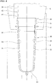
- FIG. 5 shows the injection molding mold 10 of the aforementioned injection molding unit 2, which is constituted of the lip mold 6, the cavity mold 8, and the core mold 9, as described above.
- the injection molding mold 10 is a mold for use in molding a preform for a container of the type of a PET bottle, the container body of which is large in diameter relative to the container mouth portion thereof in its final molded shape.
- the lip mold 6 includes a screw formation recessed portion 16 and a flange formation recessed portion 17.
- the lip mold 6, the cavity mold 8, and the core mold 9 of the injection molding mold 10 form a preform formation space 18 in an enclosed manner.
- the preform formation space 18 is formed from a preform mouth portion forming portion 19, a preform body forming portion 20 that is continuous with the preform mouth portion forming portion 19 and has a gap width that is uniform and wider than the gap width of the preform mouth portion forming portion 19, and a preform bottom forming portion 21 that is continuous with the preform body forming portion 20 and the bottom end of which functions as a gate for feeding a molten resin from the injection device into the preform formation space 18.
- the aforementioned core mold 9 is devised to prevent a collapse in the preform that has been molded in the aforementioned preform formation space 18, when opening the mold (removal of the molds).
- the core mold 9 is formed from a preform mouth portion inner surface forming portion 22, a preform body inner surface forming portion 23, and a preform bottom inner surface forming portion 24.
- the aforementioned preform mouth portion inner surface forming portion 22 is a portion corresponding to the aforementioned preform mouth portion forming portion 19.
- the preform body inner surface forming portion 23 is a portion corresponding to the aforementioned preform body forming portion 20.
- the preform bottom inner surface forming portion 24 is a portion corresponding to the aforementioned preform bottom forming portion 21.
- the core mold 9 includes a diameter enlarging portion 25 the diameter of which is gradually increased such that the degree of diameter enlargement is slightly larger than the degree of diameter enlargement of the preform body inner surface forming portion 23 (the degree of gradually increasing the diameter of the core mold upward of the core mold).
- the diameter enlarging portion 25 is provided between the preform body inner surface forming portion 23 and the preform mouth portion inner surface forming portion 22.
- the degree of diameter enlargement is slightly larger than the degree of diameter enlargement of the preform body inner surface forming portion 23 upward of the core mold.
- a core mold outer peripheral surface 26 of the diameter enlarging portion 25 is tapered so as to be inclined outward relative to the position of an upward extension line 28 along a core mold outer peripheral surface 27 of the preform body inner surface forming portion 23.
- the aforementioned core mold outer peripheral surface 26 is provided between the preform body inner surface forming portion 23 and the preform mouth portion inner surface forming portion 22, in particular, is continuous with a portion of the preform mouth portion inner surface forming portion 22 facing the lip mold 6.
- the upward extension line 28 along the core mold outer peripheral surface 26 is formed so as to intersect an upper end portion 19a of the aforementioned preform mouth portion forming portion 19 of the preform formation space 18.
- the diameter enlarging portion 25 of the core mold 9 is situated as follows in this embodiment.
- the diameter enlarging portion 25 is provided between a portion of the preform body inner surface forming portion 23 facing the cavity mold 8 and a portion of the preform mouth portion inner surface forming portion 22 facing the lip mold 6 through a height position 29 of a parting line between the cavity mold 8 and the lip mold 6.
- the resin is injected from the injection device into the aforementioned injection molding mold 10 structured in the injection molding unit 2 and is fed into the aforementioned preform formation space 18 of the injection molding mold 10, a preform is molded in which a surface layer that is in contact with the surrounding injection molding mold is cooled to have a low temperature and hardened into a skin layer, even though a middle layer of the charged resin has a high temperature.
- the preform is molded in the order of several seconds. Upon opening the mold, the preform is transferred to the next stretch blow molding unit 3 with the lip mold 6, to obtain the preform to be subject to stretch blowing.
- FIG. 6 shows a preform 30 molded with the aforementioned injection molding mold 10.
- the preform 30 having a bottom includes a preform mouth portion 31, a preform body 32 continuous with the preform mouth portion 31, and a preform bottom 33 continuous with the preform body 32.
- a skin layer 34 of a surface layer has a lower temperature than a middle layer 35.
- the preform body 32 and the preform bottom 33 can be expanded and deformed from the inside of the preform to the outside of the preform, to obtain the shape of a PET bottle as a final shape by stretch blowing in the stretch blow molding unit 3.
- a screw portion 36 and a flange portion 37 are integrally formed in the outer peripheral surface of the preform mouth portion 31 in accordance with the screw formation recessed portion 16 and the flange formation recessed portion 17 in the aforementioned lip mold 6, respectively.
- the skin layer 34 inside the aforementioned preform 30 has a portion corresponding to the diameter enlarging portion 25 of the aforementioned core mold 9.
- the skin layer 34 extending from an inner surface of the preform body 32 to an inner surface of the preform mouth portion 31 is a portion formed continuously from the preform body forming portion 20 on the side of the core mold 9 to the preform mouth portion forming portion 19 on the side of the core mold 9 in the aforementioned preform formation space 18 when molding a preform, and therefore, this portion is molded while being in contact with the core mold outer peripheral surface 26 of the diameter enlarging portion 25 of the core mold 9.
- the skin layer 34 that is molded while being in contact with the core mold outer peripheral surface 26 of the diameter enlarging portion 25 has a tapered shape opened upward so as to be inclined outward relative to an upward extension line 38 of the skin layer 34 in the inner surface of the preform body 32.
- the skin layer 34 that is molded while being in contact with the core mold outer peripheral surface 26 of the diameter enlarging portion 25 serves as a stress dispersion surface portion 39.
- the aforementioned stress dispersion surface portion 39 made of the skin layer 34 has the function of preventing a collapse in the shape of the preform when opening the mold.
- the stress dispersion surface portion 39 is a portion to prevent upward movement of the resin charged in the aforementioned preform body forming portion in association with an ascent of the core mold 9 due to the mold opening.
- the preform 30 is molded in a state that the skin layer 34 having a lower temperature than the middle layer 35 has a higher stiffness than the flowable resin of the middle layer 35.
- the aforementioned stress dispersion surface portion 39 is a portion having a high stiffness in the inner surface of the preform 30.
- the skin layer 34 also has a high stiffness inside the preform mouth portion 31 and the preform body 32, which are continuous with the stress dispersion surface portion 39.
- the core mold 9 is caused to ascend by mold opening, when the above-described preform 30 is obtained.
- the preform body inner surface forming portion 23 of the core mold 9 ascends, the preform body 32 of the preform 30 almost ascends in a following manner, and an ascending pressure is transferred from the preform body 32 to the aforementioned stress dispersion surface portion 39.
- the core mold outer peripheral surface 26 of the diameter enlarging portion 25 is formed widely in the vertical direction of the core mold, and the extension line 28 of the core mold outer peripheral surface 26 intersects the upper end portion 19a of the preform mouth portion forming portion 19.
- the aforementioned stress dispersion surface portion 39 is formed widely in the vertical direction of the preform 30, and the stress dispersion surface portion 39 is inclined such that an upward extension line 40 along the stress dispersion surface portion 39 intersects an upper end surface 41 of the preform mouth portion 31.
- the stress dispersion surface portion 39 When the aforementioned ascending pressure is transferred from the preform body 32 to the stress dispersion surface portion 39, a stress occurs in the stress dispersion surface portion 39 as a drag, but the stress is dispersed in the wide stress dispersion surface portion 39 without being concentrated locally. Furthermore, since the stress dispersion surface portion 39 is inclined extremely shallowly relative to a following ascending direction of the preform body (ascending direction of the core mold), the stress is properly transferred to the skin layer 34 in the inner surface of the preform mouth portion 31. Since the preform mouth portion 31 itself is thin, the ratio of the skin layer 34 to the thickness of the preform mouth portion 31 is high (the thickness of the skin layer is thick in a thickness direction of the preform mouth portion). As a result, the entire preform mouth portion 31 has an increased stiffness, and certainly supports the pressure from the stress dispersion surface portion 39. Note that, in FIG. 6 , arrows indicate the directions of the pressure in the skin layer 34.
- the injection stretch blow molding machine 1 To mold a container, after the injection stretch blow molding machine 1 molds the preform 30, as described above, the injection stretch blow molding machine 1 performs stretch blow molding at the stretch blow molding unit 3, and sends a PET bottle type container obtained by the stretch blow molding out of the machine at the ejection unit 4.
- FIG. 7 shows a conventional preform 30 for the sake of comparison. Note that the same reference numerals indicate the same components for ease of explanation.
- the conventional preform 30 molded in an injection molding unit of an injection stretch blow molding machine had a step portion 42 in an inner surface of a preform body 32 on the side of a preform mouth portion 31, in order to absorb the difference in thickness between the preform mouth portion 31 and the preform body 32.
- the entire step portion 42 was formed in an area corresponding to a cavity mold 8, and an inner peripheral surface of the step portion 42 was inclined such that an upward extension line along the inner peripheral surface intersected a base end of the preform mouth portion 31.
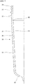
- FIG. 8 shows an example of the contrivance for the shape of the preform formation space, when molding a preform of the present invention, for ease in charging the resin into the preform formation space of the injection molding mold.
- a cylindrical portion 43 the diameter of which is reduced downward is provided between the aforementioned preform body forming portion 20 and the aforementioned preform bottom forming portion 21.
- the cylindrical portion 43 is tapered such that a downward tangent 44 of the cylindrical portion 43 in the vertical direction is inclined to a center line 18a of the preform formation space, with respect to a downward extension line 45 of the preform body forming portion 20.
- the resin when the resin is fed from the gate, the resin moves with a reduced resistance from the preform bottom forming portion 21 to the preform body forming portion 20, thus facilitating charging the resin in a smoother manner.
- This provides a favorable effect in acceleration of the ascent timing of the core mold.
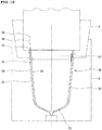
- FIG. 9 shows an example of molding a preform to obtain a jar as a final molded product.
- the jar itself as the final molded product is a jar the mouth portion of which is covered with a lid.
- a fit projection molding recessed portion 46 is provided in an outer peripheral surface of the preform mouth portion forming portion. Note that the same reference numerals as in the above-described embodiment indicate the same types of components, and a description thereof will be omitted.
- the aforementioned injection stretch blow molding machine 1 performs the stages of preform molding and stretch blow molding, and then a final molded product is sent out of the machine to obtain a jar.
- the degree of enlargement of the diameter of the core mold is slightly larger than the degree of diameter enlargement of a preform body inner surface forming portion 23 in an upward direction of the core mold.
- a core mold outer peripheral surface 26 of the diameter enlarging portion 25 is tapered so as to be inclined outward relative to the position of an upward extension line 28 along a core mold outer peripheral surface 27 of the preform body inner surface forming portion 23.
- the above-described core mold outer peripheral surface 26 is continuous with an area facing the lip mold 6 between the preform body inner surface forming portion 23 and a preform mouth portion inner surface forming portion 22.
- An upward extension line 28 along the core mold outer peripheral surface 26 intersects an upper end portion 19a of a preform mouth portion forming portion 19.
- the diameter enlarging portion 25 is provided so as to extend between a portion of the preform body inner surface forming portion 23 facing the cavity mold 8 and a portion of the preform mouth portion inner surface forming portion 22 facing the lip mold 6 through the height position 29 of the parting line between the cavity mold 8 and the lip mold 6. This disposition makes the tapered core mold outer peripheral surface 26 of the diameter enlarging portion 25 formed widely in the vertical direction of the core mold.
- FIG. 10 shows a preform 30 molded with an injection molding mold 10 according to the above-described other embodiment.
- a skin layer 34 of a surface layer has a lower temperature than a middle layer 35.
- a preform body 32 and a preform bottom 33 can be expanded and deformed from the inside of the preform to the outside of the preform, to obtain the shape of a jar as a final shape by stretch blowing in the stretch blow molding unit 3.
- the skin layer 34 extending from an inner surface of the preform body 32 to an inner surface of a preform mouth portion 31 is a portion formed continuously from the preform body forming portion 20 on the side of the core mold 9 to the preform mouth portion forming portion 19 on the side of the core mold 9 in the preform formation space 18 when molding a preform, and therefore, this portion is molded while being in contact with the core mold outer peripheral surface 26 of the diameter enlarging portion 25 of the core mold 9.
- the skin layer 34 that is molded while being in contact with the core mold outer peripheral surface 26 of the diameter enlarging portion 25 has a tapered shape opened upward so as to be inclined outward relative to an upward extension line 38 of the skin layer 34 in the inner surface of the preform body 32.
- the skin layer 34 that is molded with the core mold outer peripheral surface 26 serves as a stress dispersion surface portion 39.
- the aforementioned stress dispersion surface portion 39 in the inner surface of the preform 30 has an increased stiffness, and the skin layer 34 inside the preform mouth portion 31 and the skin layer 34 inside the preform body 32 also have an increased stiffness.
- the core mold outer peripheral surface 26 of the diameter enlarging portion 25 is formed widely in the vertical direction of the core mold, and the extension line 28 of the core mold outer peripheral surface 26 intersects the upper end portion 19a of the preform mouth portion forming portion 19.
- the stress dispersion surface portion 39 is formed widely in the vertical direction of the preform 30, and the stress dispersion surface portion 39 is inclined such that an upward extension line 40 along the stress dispersion surface portion 39 intersects an upper end surface 41 of the preform mouth portion 31.
- the stress dispersion surface portion 39 When the ascending pressure is transferred from the preform body 32 to the stress dispersion surface portion 39, a stress occurs in the stress dispersion surface portion 39 as a drag, but the stress is dispersed in the wide stress dispersion surface portion 39 without being concentrated locally. Furthermore, since the stress dispersion surface portion 39 is inclined extremely shallowly relative to a following ascending direction of the preform body, the stress is properly transferred to the skin layer 34 in the inner surface of the preform mouth portion 31. Since the preform mouth portion 31 itself is thin, the ratio of the skin layer 34 to the thickness of the preform mouth portion 31 is high (the thickness of the skin layer is thick in a thickness direction of the preform mouth portion). Just as with the above-described embodiment, the pressure from the stress dispersion surface portion 39 is certainly supported. In FIG. 10 , arrows indicate the directions of the pressure in the skin layer 34.
- the preform is molded in a molten state having very little crystallization in the injection molding unit of the injection stretch blow molding machine having the aforementioned structure according to the embodiments.
- a shaped portion of the preform that is provided to mold a container is thinned and stretched, thus allowing formation of a molded product having an extremely small number of crystallized portions owing to rapid cooling.
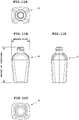
- a preform having a thickness of 7.5 mm was formed of a polyethylene terephthalate resin, and thus a container A having the shape of FIG. 11 was molded.
- a container body is elliptical in plan having a maximum width of a wide portion of 50 mm.
- a container height is 95 mm.
- the thickness of a shaped portion of the container body and the like is 1.6 to 2.1 mm. The transparency of the body of the obtained container was measured.
- Haze is obtained as the transparency.
- a test method for measuring a haze value is as follows.
- the injection cooling time (total time) is 42 seconds.
Landscapes
- Engineering & Computer Science (AREA)
- Mechanical Engineering (AREA)
- Manufacturing & Machinery (AREA)
- Physics & Mathematics (AREA)
- Thermal Sciences (AREA)
- Blow-Moulding Or Thermoforming Of Plastics Or The Like (AREA)
- Moulds For Moulding Plastics Or The Like (AREA)
- Injection Moulding Of Plastics Or The Like (AREA)
- Processing And Handling Of Plastics And Other Materials For Molding In General (AREA)
Abstract
a cavity mold,
a lip mold for molding an outer peripheral surface of a preform mouth portion, the lip mold disposed on a bottom surface of the rotating plate and configured to descend toward the cavity mold together with the rotating plate unit when it is situated in a position corresponding to the injection molding unit by rotation of the rotating plate, and
a core mold that ascends and descends insertably into the cavity mold through the cavity mold and the lip mold to form_ a preform formation space enclosed by the lip mold, the cavity mold, and the core mold,
(ii) the preform formation space is formed from
a preform mouth portion forming portion,
a preform body forming portion that is continuous with the preform mouth portion forming portion and has a gap width uniform and wider than a gap width of the preform mouth portion forming portion, and
a preform bottom forming portion that is continuous with the preform body forming portion and has a lower end located on a side of a gate,
(iii) the core mold includes
a preform mouth portion inner surface forming portion corresponding to the preform mouth portion forming portion,
a preform body inner surface forming portion corresponding to the preform body forming portion,
a preform bottom inner surface forming portion corresponding to the preform bottom forming portion, and
a diameter enlarging portion in which a diameter of the core mold is gradually enlarged from the preform body inner surface forming portion to the preform mouth portion inner surface forming portion,
(iv) in the diameter enlarging portion, a core mold outer peripheral surface is tapered so as to be inclined outward relative to a position of an upper extension line along the core mold outer peripheral surface in the preform body inner surface forming portion,
(v) the core mold outer peripheral surface in the diameter enlarging portion is continuous between the preform body inner surface forming portion and a portion of the preform mouth portion inner surface forming portion facing the lip mold, and
(vi) the core mold outer peripheral surface in the diameter enlarging portion is inclined such that an upward extension line along the core mold outer peripheral surface of the diameter enlarging portion intersects an upper end portion of the preform mouth portion forming portion.
Description
- The present invention relates to an injection mold for a molding unit of an injection stretch blow molding machine, a method for molding a preform, and a method for molding a container. In particular, the invention relates to an injection molding mold according to the pre-characterizing features of
claim 1, a preform molding method according to the pre-characterizing features ofclaim 7, and a container molding method according to the pre-characterizing features ofclaim 11. - Conventionally, injection stretch blow molding machines are used to mold containers. The injection stretch blow molding machine is provided with three stations, i.e. an injection molding unit into which a molten resin is fed from a connected injection device, a stretch blow molding unit for molding a preform molded by the injection molding unit into a container, and an ejection unit for transferring the container molded by the stretch blow molding unit out of the machine.
- Furthermore, in some of the injection stretch blow molding machines, the three stations are disposed in the same circumference at the same angular intervals, and a rotating plate unit having a rotating plate, which transfers the molded preform and container by circular movement, is provided above the three stations.
- The aforementioned rotating plate of the injection stretch blow molding machine has lip molds on its bottom surface. The lip mold is used for forming an outer peripheral surface of a preform mouth portion, and for transferring the molded preform and container by catching the mouth portion of the preform.
- As described above, the injection molding unit, the stretch blow molding unit, and the ejection unit are disposed about a rotational axis of the rotating plate at the same angular intervals (120 degrees). The rotating plate stops and the rotating plate unit descends, whenever the rotating plate turns a certain rotation angle (120 degrees). Whenever the rotating plate unit descends, the lip molds provided on the bottom surface of the rotating plate correspond to the injection molding unit, the stretch blow molding unit, and the ejection unit. The descent of the lip mold forms an injection molding mold in the injection molding unit. The descent of the lip mold forms a stretch blow molding mold in the stretch blow molding unit.
- For example, as described in
Patent Literature 1, the injection molding mold formed in the injection molding unit is constituted of a combination of the descended lip mold, a cavity mold fixed in the injection molding unit, and a core mold that is movable upward and downward in the injection molding unit. When the aforementioned rotating plate unit descends, the lip mold is overlaid on the cavity mold fixed in the injection molding unit, and the core mold, which is movable upward and downward in the injection molding unit, is inserted into the cavity mold through the lip mold. By clamping the molds, preform formation space that is enclosed by the lip mold, the cavity mold, and the core mold is formed. - By feeding a resin injected from the injection device into the aforementioned preform formation space so as to fill the preform formation space with the resin, a preform is molded. After the order of several seconds has elapsed from the injection of the resin, the lip mold as well as the core mold ascends (the rotating plate unit ascends) and opens (the molds are apart), so that the molded preform is moved to an upper portion of the injection molding unit together with the lip mold.
- The lip mold has the function of holding and transferring a molded preform, and the function of holding a container molded in the next molding stage, i.e., the stretch blow molding unit and transferring the container to the ejection unit, as well as forms an outer peripheral surface of a mouth portion of the preform as a part of the injection molding mold. The rotating plate of the rotating plate unit turns at a certain rotation angle and stops such that the lip molds are situated in positions corresponding to the aforementioned three stations, and the rotating plate unit ascends and descends. A preform transferred by the lip mold is sent from the injection molding unit to the stretch blow molding unit, and is molded into a container by stretch blow molding. The container formed in the stretch blow molding unit by stretch blow molding is transferred to the ejection unit with the lip mold for holding the mouth portion of the container. In the ejection unit, the lip mold releases the hold of the mouth portion of the container to send the molded container out of the machine.
- Patent Literature 1: Japanese Patent Application Laid-Open No.
Hei. 11-188779 - This patent document discloses an injection mold for an injection stretch blow molding machine having all the pre-characterizing features of
claim 1. - In the conventional injection molding mold structured in the injection molding unit of the aforementioned injection stretch blow molding machine, the preform formation space is constituted of a preform mouth portion forming portion, a preform body forming portion that is continuous with the preform mouth portion forming portion and has a gap width that is uniform and wider than the gap width of the preform mouth portion forming portion, and a preform bottom forming portion that is continuous with the preform body forming portion and is located on the side of a gate of a resin inlet port at its bottom end.
- In a preform, a preform body and a preform bottom are required to have a large amount of resin, because of being expanded largely by stretch blow molding. Thus, the gap widths of the aforementioned preform body forming portion and the preform bottom forming portion in the preform formation space are wider than the gap width of the aforementioned preform mouth portion forming portion in the preform formation space. On the other hand, since a preform mouth portion has the same shape as a container mouth portion, the gap width of the preform mouth portion forming portion in the preform formation space is narrower than the gap widths of the preform body forming portion and the preform bottom forming portion.
- Note that, there is a case where the preform mouth portion forming portion is provided with a screw forming portion, a flange forming portion, or the like that is convex outward. Even in the case, the preform mouth portion forming portion itself does not change and has a narrow gap width.
- As described above, since the gap width of the preform body forming portion, which is continuous with the preform mouth portion forming portion, is wider than the gap width of the preform mouth portion forming portion in the preform formation space, the gap width of the preform body forming portion is conventionally made narrow at a portion in the vicinity of the preform mouth portion forming portion. To be more specific, as shown in
Patent Literature 1, a preform body inner surface forming portion of the core mold is tapered in the vicinity of a preform mouth portion inner surface forming portion. - By the way, to increase the molding efficiency in the injection stretch blow molding machine having the injection molding mold of the aforementioned structure, a molding cycle of a preform in the injection molding unit is required to be reduced, and it is studied to accelerate mold opening timing, in other words, ascent timing of the core mold.
- In the preform that is formed by filling the aforementioned preform formation space of the injection molding mold with the resin, a surface layer that is in contact with the injection molding mold (the lip mold, the cavity mold, and the core mold) is a skin layer having higher stiffness due to temperature reduction than a middle layer that is not in contact with the injection molding mold. The skin layer is also formed in a surface layer that is in contact with the aforementioned tapered portion of the preform mouth portion inner surface forming portion of the core mold.
- When the core mold is caused to ascend in conventional timing, a preform body corresponding to the preform body inner surface forming portion of the core mold almost ascends in a following manner, and a stress concentrates on the preform at a portion corresponding to the aforementioned tapered portion of the core mold. However, the skin layer formed in the tapered portion resists the stress, and therefore the preform body is prevented from ascending.
- However, when the core mold is caused to ascend in early timing, the skin layer formed in the tapered portion may easily have insufficient stiffness. When the core mold ascends in this state, the stress transferred due to the following ascent of the preform body collapses the skin layer in the tapered portion. As a result, the preform body ascends in a following manner and collides against the preform mouth portion, and thus the shape of the entire preform collapses. Thus, there is a problem that the preform cannot be used in the next stretch blow molding stage. For this reason, the mold opening timing cannot be accelerated, and the molding efficiency cannot be increased.
- It is the goal of the preform disclosed in the aforementioned document to decrease the weight of the neck of the preform formed by injection molding and to improve strength and heat-resisting properties of the neck by stretch-blowing from neck to the whole of the preform. This document does not disclose any feature for preventing the ascend of the preform body in the injection molding mold formed in the injection molding unit of the injection stretch blow molding machine when ascending the core mold to open the mold, by dispersing stress such that the stress does not concentrate on a portion between the preform mouth portion and the preform body at which a thickness changes, using the skin layer formed in the portion.
- Considering the aforementioned circumstances, a subject of the present invention is to prevent the following ascent of the preform body in the injection molding mold formed in the injection molding unit of the injection stretch blow molding machine, when ascending the core mold to open the mold, by dispersing stress such that the stress does not concentrate on a portion between the preform mouth portion and the preform body at which a thickness changes, using the skin layer formed in the portion. Thus, an object of the present invention is to improve the productivity of the injection stretch blow molding machine.
- Patent literature 2:
US 2006/065992 A - This document discloses a method of forming at least a portion of a preform or closure comprising the following steps: Producing lamella material; depositing said lamella material in a mold cavity section; and moving a core section having a core relative to the mold cavity section to compress the lamella material between the core and the mold cavity section, the core section and the mold cavity section having an open and a closed position, the core and the mold cavity section cooperate to define a cavity in the shape of at least a portion of a preform or closure when in the closed position. Furthermore, this document discloses a compression molding system for producing multilayer articles, comprising: a mandrel movable between an open position and a closed position; a mold cavity configured to receive the mandrel, the mold cavity and the mandrel cooperate to define a cavity in a shape of a preform; and a material source configured to drop lamella material suitable for molding into the cavity.
- The present invention has been made in consideration of the aforementioned subject. The present invention provides an injection molding mold for an injection molding unit of an injection stretch blow molding machine according to the characterizing features of
claim 1, a preform molding method according to the characterizing features ofclaim 7, and a container molding method according to the characterizing features ofclaim 11. - Preferred embodiments of the invention are the subject of the dependent claims.
- According to the present invention, a preform having a bottom including a preform mouth portion, a preform body that is continuous with the preform mouth portion and thicker than the preform mouth portion, and a preform bottom that is continuous with the preform body, the skin layer of the surface layer has a lower temperature than the middle layer can be molded. In this preform, the skin layer extending between the inner surface of the preform body and the inner surface of the preform mouth portion is tapered upward so as to be inclined outward with respect to the upward extension line of the skin layer in the inner surface of the preform body.
- Therefore, when the preform is molded by the inventive injection molding mold of the injection molding unit of the injection stretch blow molding machine, the skin layer is formed widely in a vertical direction of the preform in an inner surface of a thickness change portion between the preform mouth portion and the preform body, so as to extend between a height position of an inner surface in a preform mouth portion area and a height position of an inner surface in a preform body area. Even if the body of the preform almost ascends in a following manner due to an ascent of the core mold, the tapered and wide skin layer disperses a stress from the side of the preform body, and prevents local concentration of the stress.
- Therefore, when the body of the preform almost ascends in a following manner, the skin layer, which extends between the height position of the inner surface in the preform mouth portion area and the height position of the inner surface in the preform body area, prevents the following ascent. Therefore, the present invention can accelerate ascent timing of the core mold, and thus has the superior effect in which the preform is transferred to the next stretch blow molding stage, while reducing a preform molding time.
-
-
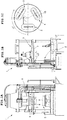
FIG. 1 shows an injection stretch blow molding machine that carries out the present invention, in which (a) is an explanatory view of an injection molding unit viewed from the front, (b) is an explanatory view of the injection molding unit viewed from the side, and (c) is an explanatory view showing the disposition of the injection molding unit, a stretch blow molding unit, and an ejection unit. -
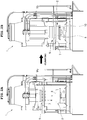
FIG. 2 shows movement of the injection molding unit according to the present invention, in which (a) is an explanatory view showing a state in which a lip mold corresponds to a cavity mold, and (b) is an explanatory view showing a state of closing the molds. -
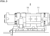
FIG. 3 is an explanatory view of a blow mold in the stretch blow molding unit according to the present invention. -
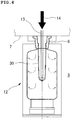
FIG. 4 is an explanatory view of stretch blowing in the stretch blow mold according to the present invention. -
FIG. 5 is an explanatory view schematically showing an injection molding mold according to the present invention. -
FIG. 6 is an explanatory view showing an example of a preform molded in the injection molding unit according to the present invention. -
FIG. 7 is an explanatory view showing the shape of a conventional preform, for the sake of comparison. -
FIG. 8 is an explanatory view of a modified example of an injection molding mold according to the present invention. -
FIG. 9 is an explanatory view schematically showing an injection molding mold according to another embodiment of the present invention. -
FIG. 10 is an explanatory view showing the shape of a preform according to the other embodiment of the present invention. -
FIG. 11 shows a sample container, in which (a) is an explanatory view viewed from above, (b) is an explanatory view viewed from the front, (c) is an explanatory view viewed from the bottom, and (d) is an explanatory view viewed from the side. - The present invention will be described in detail on the basis of embodiments illustrated in
FIG. 1 to FIG. 11 . In the drawings, thereference numeral 1 denotes an injection stretch blow molding machine. As shown inFIG. 1 , the injection stretchblow molding machine 1 is provided with three stations, which includes aninjection molding unit 2, a stretchblow molding unit 3, and an ejection unit 4, on a lower base plate. Further included is arotating plate unit 5 that is movable upward and downward in a vertical direction above the three stations. - The aforementioned
injection molding unit 2, stretchblow molding unit 3, and ejection unit 4 are disposed in the same circumference at intervals of a constant angle (120 degrees). In the aforementionedrotating plate unit 5, arotating plate 7, which haslip molds 6 each for forming an outer peripheral surface of a preform mouth portion and for transferring a preform on its bottom surface, is provided rotatably about a rotation axis passing through the center of the disposition of the stations so as to stop every time therotating plate 7 turns at a constant rotation angle (120 degrees). Whenever therotating plate 7 stops, thelip molds 6 are situated in positions corresponding to theinjection molding unit 2, the stretchblow molding unit 3, and the ejection unit 4. - When the
rotating plate 7 temporarily stops and therotating plate unit 5 descends, as described above, acavity mold 8 fixed in the position of the aforementionedinjection molding unit 2, thelip mold 6, and acore mold 9 that is movable upward and downward in theinjection molding unit 2 and is inserted into thecavity mold 8 through thelip mold 6 form aninjection molding mold 10 in theinjection molding unit 2, as shown inFIG. 2 . - In the aforementioned stretch
blow molding unit 3, a pair of split molds i.e.blow molds 11 disposed in the stretchblow molding unit 3, as shown inFIG. 3 , and thelip mold 6 form astretch blow mold 12. As shown inFIG. 4 , stretch blow molding is performed in the stretchblow molding unit 3, by stretching operation using astretch rod 13 inserted into theblow mold 11 and blow air blow-in 14 from blow air supply unit. - In the aforementioned ejection unit 4, a molded
product reception port 15 is formed under thelip mold 6 that is situated in the position corresponding to the ejection unit 4. When thelip mold 6 releases the hold of a molded product, the molded product is sent out of the machine. - In the injection stretch
blow molding machine 1 including theinjection molding unit 2, the stretchblow molding unit 3, the ejection unit 4, and therotating plate unit 5, as described above, a resin is fed from an injection device into theinjection molding mold 10 formed by thelip mold 6 disposed in theinjection molding unit 2, to mold a preform. The molded preform is transferred to the stretchblow molding unit 3 by an ascent movement and a circular movement of thelip mold 6 due to an ascent of therotating plate unit 5 and a turn of therotating plate 7 after opening the mold. In the stretchblow molding unit 3, the preform is molded into a container by stretch blowing. Furthermore, the transfer of thelip mold 6 causes the molded container to be transferred from the stretchblow molding unit 3 to the ejection unit 4. In the ejection unit 4, since thelip mold 6 releases the hold of the container, the container, i.e., the molded product is sent out of the machine. -
FIG. 5 shows theinjection molding mold 10 of the aforementionedinjection molding unit 2, which is constituted of thelip mold 6, thecavity mold 8, and thecore mold 9, as described above. Theinjection molding mold 10 is a mold for use in molding a preform for a container of the type of a PET bottle, the container body of which is large in diameter relative to the container mouth portion thereof in its final molded shape. Thus, thelip mold 6 includes a screw formation recessedportion 16 and a flange formation recessedportion 17. - As shown in
FIG. 5 , thelip mold 6, thecavity mold 8, and thecore mold 9 of theinjection molding mold 10 form apreform formation space 18 in an enclosed manner. Thepreform formation space 18 is formed from a preform mouthportion forming portion 19, a preformbody forming portion 20 that is continuous with the preform mouthportion forming portion 19 and has a gap width that is uniform and wider than the gap width of the preform mouthportion forming portion 19, and a preformbottom forming portion 21 that is continuous with the preformbody forming portion 20 and the bottom end of which functions as a gate for feeding a molten resin from the injection device into thepreform formation space 18. - The
aforementioned core mold 9 is devised to prevent a collapse in the preform that has been molded in the aforementionedpreform formation space 18, when opening the mold (removal of the molds). Thecore mold 9 is formed from a preform mouth portion innersurface forming portion 22, a preform body innersurface forming portion 23, and a preform bottom innersurface forming portion 24. - The aforementioned preform mouth portion inner
surface forming portion 22 is a portion corresponding to the aforementioned preform mouthportion forming portion 19. The preform body innersurface forming portion 23 is a portion corresponding to the aforementioned preformbody forming portion 20. The preform bottom innersurface forming portion 24 is a portion corresponding to the aforementioned preformbottom forming portion 21. - The
core mold 9 includes adiameter enlarging portion 25 the diameter of which is gradually increased such that the degree of diameter enlargement is slightly larger than the degree of diameter enlargement of the preform body inner surface forming portion 23 (the degree of gradually increasing the diameter of the core mold upward of the core mold). As shown in the drawing, thediameter enlarging portion 25 is provided between the preform body innersurface forming portion 23 and the preform mouth portion innersurface forming portion 22. - In the
diameter enlarging portion 25, as described above, the degree of diameter enlargement is slightly larger than the degree of diameter enlargement of the preform body innersurface forming portion 23 upward of the core mold. Thus, a core mold outerperipheral surface 26 of thediameter enlarging portion 25 is tapered so as to be inclined outward relative to the position of anupward extension line 28 along a core mold outerperipheral surface 27 of the preform body innersurface forming portion 23. - Furthermore, the aforementioned core mold outer
peripheral surface 26 is provided between the preform body innersurface forming portion 23 and the preform mouth portion innersurface forming portion 22, in particular, is continuous with a portion of the preform mouth portion innersurface forming portion 22 facing thelip mold 6. Theupward extension line 28 along the core mold outerperipheral surface 26 is formed so as to intersect anupper end portion 19a of the aforementioned preform mouthportion forming portion 19 of thepreform formation space 18. - In order to continue the core mold outer
peripheral surface 26 of the aforementioneddiameter enlarging portion 25 of thecore mold 9 from a portion between the preform body innersurface forming portion 23 and the preform mouth portion innersurface forming portion 22 facing thelip mold 6, as described above, thediameter enlarging portion 25 is situated as follows in this embodiment. - Specifically, the
diameter enlarging portion 25 is provided between a portion of the preform body innersurface forming portion 23 facing thecavity mold 8 and a portion of the preform mouth portion innersurface forming portion 22 facing thelip mold 6 through aheight position 29 of a parting line between thecavity mold 8 and thelip mold 6. By disposing thediameter enlarging portion 25 in this manner, the tapered core mold outerperipheral surface 26 of thediameter enlarging portion 25 is formed so as to be enlarged in a vertical direction of the core mold. - In the aforementioned injection stretch
blow molding machine 1, since the resin is injected from the injection device into the aforementionedinjection molding mold 10 structured in theinjection molding unit 2 and is fed into the aforementionedpreform formation space 18 of theinjection molding mold 10, a preform is molded in which a surface layer that is in contact with the surrounding injection molding mold is cooled to have a low temperature and hardened into a skin layer, even though a middle layer of the charged resin has a high temperature. The preform is molded in the order of several seconds. Upon opening the mold, the preform is transferred to the next stretchblow molding unit 3 with thelip mold 6, to obtain the preform to be subject to stretch blowing. -
FIG. 6 shows apreform 30 molded with the aforementionedinjection molding mold 10. Thepreform 30 having a bottom includes apreform mouth portion 31, apreform body 32 continuous with thepreform mouth portion 31, and a preform bottom 33 continuous with thepreform body 32. Askin layer 34 of a surface layer has a lower temperature than amiddle layer 35. Thepreform body 32 and the preform bottom 33 can be expanded and deformed from the inside of the preform to the outside of the preform, to obtain the shape of a PET bottle as a final shape by stretch blowing in the stretchblow molding unit 3. - Note that, a
screw portion 36 and aflange portion 37 are integrally formed in the outer peripheral surface of thepreform mouth portion 31 in accordance with the screw formation recessedportion 16 and the flange formation recessedportion 17 in theaforementioned lip mold 6, respectively. - The
skin layer 34 inside theaforementioned preform 30 has a portion corresponding to thediameter enlarging portion 25 of theaforementioned core mold 9. In other words, theskin layer 34 extending from an inner surface of thepreform body 32 to an inner surface of thepreform mouth portion 31 is a portion formed continuously from the preformbody forming portion 20 on the side of thecore mold 9 to the preform mouthportion forming portion 19 on the side of thecore mold 9 in the aforementionedpreform formation space 18 when molding a preform, and therefore, this portion is molded while being in contact with the core mold outerperipheral surface 26 of thediameter enlarging portion 25 of thecore mold 9. - The
skin layer 34 that is molded while being in contact with the core mold outerperipheral surface 26 of thediameter enlarging portion 25 has a tapered shape opened upward so as to be inclined outward relative to anupward extension line 38 of theskin layer 34 in the inner surface of thepreform body 32. Theskin layer 34 that is molded while being in contact with the core mold outerperipheral surface 26 of thediameter enlarging portion 25 serves as a stressdispersion surface portion 39. - The aforementioned stress
dispersion surface portion 39 made of theskin layer 34 has the function of preventing a collapse in the shape of the preform when opening the mold. The stressdispersion surface portion 39 is a portion to prevent upward movement of the resin charged in the aforementioned preform body forming portion in association with an ascent of thecore mold 9 due to the mold opening. - In the
preform formation space 18 of theinjection molding mold 10, thepreform 30 is molded in a state that theskin layer 34 having a lower temperature than themiddle layer 35 has a higher stiffness than the flowable resin of themiddle layer 35. The aforementioned stressdispersion surface portion 39 is a portion having a high stiffness in the inner surface of thepreform 30. In the same manner, theskin layer 34 also has a high stiffness inside thepreform mouth portion 31 and thepreform body 32, which are continuous with the stressdispersion surface portion 39. - In the injection stretch
blow molding machine 1, thecore mold 9 is caused to ascend by mold opening, when the above-describedpreform 30 is obtained. When the preform body innersurface forming portion 23 of thecore mold 9 ascends, thepreform body 32 of thepreform 30 almost ascends in a following manner, and an ascending pressure is transferred from thepreform body 32 to the aforementioned stressdispersion surface portion 39. - As described above, the core mold outer
peripheral surface 26 of thediameter enlarging portion 25 is formed widely in the vertical direction of the core mold, and theextension line 28 of the core mold outerperipheral surface 26 intersects theupper end portion 19a of the preform mouthportion forming portion 19. Thus, the aforementioned stressdispersion surface portion 39 is formed widely in the vertical direction of thepreform 30, and the stressdispersion surface portion 39 is inclined such that anupward extension line 40 along the stressdispersion surface portion 39 intersects anupper end surface 41 of thepreform mouth portion 31. - When the aforementioned ascending pressure is transferred from the
preform body 32 to the stressdispersion surface portion 39, a stress occurs in the stressdispersion surface portion 39 as a drag, but the stress is dispersed in the wide stressdispersion surface portion 39 without being concentrated locally. Furthermore, since the stressdispersion surface portion 39 is inclined extremely shallowly relative to a following ascending direction of the preform body (ascending direction of the core mold), the stress is properly transferred to theskin layer 34 in the inner surface of thepreform mouth portion 31. Since thepreform mouth portion 31 itself is thin, the ratio of theskin layer 34 to the thickness of thepreform mouth portion 31 is high (the thickness of the skin layer is thick in a thickness direction of the preform mouth portion). As a result, the entirepreform mouth portion 31 has an increased stiffness, and certainly supports the pressure from the stressdispersion surface portion 39. Note that, inFIG. 6 , arrows indicate the directions of the pressure in theskin layer 34. - Therefore, when the
core mold 9 is caused to ascend, a following ascent of thepreform body 32 is certainly prevented without collapsing the stressdispersion surface portion 39, and the mold is opened in an appropriate manner without collapsing the shape of thepreform 30, thus having the effect of accelerating ascent timing of the core mold. - To mold a container, after the injection stretch
blow molding machine 1 molds thepreform 30, as described above, the injection stretchblow molding machine 1 performs stretch blow molding at the stretchblow molding unit 3, and sends a PET bottle type container obtained by the stretch blow molding out of the machine at the ejection unit 4. -
FIG. 7 shows aconventional preform 30 for the sake of comparison. Note that the same reference numerals indicate the same components for ease of explanation. Theconventional preform 30 molded in an injection molding unit of an injection stretch blow molding machine had astep portion 42 in an inner surface of apreform body 32 on the side of apreform mouth portion 31, in order to absorb the difference in thickness between thepreform mouth portion 31 and thepreform body 32. - The
entire step portion 42 was formed in an area corresponding to acavity mold 8, and an inner peripheral surface of thestep portion 42 was inclined such that an upward extension line along the inner peripheral surface intersected a base end of thepreform mouth portion 31. - To mold a preform having the conventional shape, when a core mold was caused to ascend with timing for obtaining a preform of the present invention, it was confirmed that a following ascending pressure of the preform body collapsed a skin layer in the
step portion 42, and the collapse even caused a collapse of the preform body. - When comparing between the time for molding the conventional preform as a comparison from a feed of the resin (injection) to an ascent of the core mold (mold opening) and the time for molding the preform of the present invention from a feed of the resin (injection) to an ascent of the core mold (mold opening), it was confirmed that the time was reduced by the order of 20%.
-
FIG. 8 shows an example of the contrivance for the shape of the preform formation space, when molding a preform of the present invention, for ease in charging the resin into the preform formation space of the injection molding mold. - In this modified example, in the
preform formation space 18, acylindrical portion 43 the diameter of which is reduced downward is provided between the aforementioned preformbody forming portion 20 and the aforementioned preformbottom forming portion 21. Thecylindrical portion 43 is tapered such that adownward tangent 44 of thecylindrical portion 43 in the vertical direction is inclined to acenter line 18a of the preform formation space, with respect to adownward extension line 45 of the preformbody forming portion 20. - According to this structure, when the resin is fed from the gate, the resin moves with a reduced resistance from the preform
bottom forming portion 21 to the preformbody forming portion 20, thus facilitating charging the resin in a smoother manner. This provides a favorable effect in acceleration of the ascent timing of the core mold. - The above-described embodiment describes molding of the preform to obtain the PET bottle type molded product the body of which has a large diameter relative to the diameter of the mouth portion, as a final molded product, but the present invention is not limited to the above-described embodiment.
FIG. 9 shows an example of molding a preform to obtain a jar as a final molded product. The jar itself as the final molded product is a jar the mouth portion of which is covered with a lid. A fit projection molding recessedportion 46 is provided in an outer peripheral surface of the preform mouth portion forming portion. Note that the same reference numerals as in the above-described embodiment indicate the same types of components, and a description thereof will be omitted. - In this embodiment, just as with the above-described embodiment, the aforementioned injection stretch
blow molding machine 1 performs the stages of preform molding and stretch blow molding, and then a final molded product is sent out of the machine to obtain a jar. Out of alip mold 6, acavity mold 8, and acore mold 9 that constitute a preform mouthportion forming space 18, thecore mold 9 is provided with adiameter enlarging portion 25. - In the
diameter enlarging portion 25, the degree of enlargement of the diameter of the core mold is slightly larger than the degree of diameter enlargement of a preform body innersurface forming portion 23 in an upward direction of the core mold. A core mold outerperipheral surface 26 of thediameter enlarging portion 25 is tapered so as to be inclined outward relative to the position of anupward extension line 28 along a core mold outerperipheral surface 27 of the preform body innersurface forming portion 23. - The above-described core mold outer
peripheral surface 26 is continuous with an area facing thelip mold 6 between the preform body innersurface forming portion 23 and a preform mouth portion innersurface forming portion 22. Anupward extension line 28 along the core mold outerperipheral surface 26 intersects anupper end portion 19a of a preform mouthportion forming portion 19. - In order to continue the core mold outer
peripheral surface 26 of the aforementioneddiameter enlarging portion 25 from a portion facing thelip mold 6 between the preform body innersurface forming portion 23 and the preform mouth portion innersurface forming portion 22, also in this embodiment, thediameter enlarging portion 25 is provided so as to extend between a portion of the preform body innersurface forming portion 23 facing thecavity mold 8 and a portion of the preform mouth portion innersurface forming portion 22 facing thelip mold 6 through theheight position 29 of the parting line between thecavity mold 8 and thelip mold 6. This disposition makes the tapered core mold outerperipheral surface 26 of thediameter enlarging portion 25 formed widely in the vertical direction of the core mold. -
FIG. 10 shows apreform 30 molded with aninjection molding mold 10 according to the above-described other embodiment. In thepreform 30, askin layer 34 of a surface layer has a lower temperature than amiddle layer 35. Apreform body 32 and a preform bottom 33 can be expanded and deformed from the inside of the preform to the outside of the preform, to obtain the shape of a jar as a final shape by stretch blowing in the stretchblow molding unit 3. - The
skin layer 34 extending from an inner surface of thepreform body 32 to an inner surface of apreform mouth portion 31 is a portion formed continuously from the preformbody forming portion 20 on the side of thecore mold 9 to the preform mouthportion forming portion 19 on the side of thecore mold 9 in thepreform formation space 18 when molding a preform, and therefore, this portion is molded while being in contact with the core mold outerperipheral surface 26 of thediameter enlarging portion 25 of thecore mold 9. - The
skin layer 34 that is molded while being in contact with the core mold outerperipheral surface 26 of thediameter enlarging portion 25 has a tapered shape opened upward so as to be inclined outward relative to anupward extension line 38 of theskin layer 34 in the inner surface of thepreform body 32. Just as with the above-described embodiment, theskin layer 34 that is molded with the core mold outerperipheral surface 26 serves as a stressdispersion surface portion 39. - In the
preform 30 molded in thepreform formation space 18, the aforementioned stressdispersion surface portion 39 in the inner surface of thepreform 30 has an increased stiffness, and theskin layer 34 inside thepreform mouth portion 31 and theskin layer 34 inside thepreform body 32 also have an increased stiffness. - When the preform body inner
surface forming portion 23 of thecore mold 9 ascends by mold opening, thepreform body 32 of thepreform 30 almost ascends in a following manner, and an ascending pressure is transferred from thepreform body 32 to the stressdispersion surface portion 39. - The core mold outer
peripheral surface 26 of thediameter enlarging portion 25 is formed widely in the vertical direction of the core mold, and theextension line 28 of the core mold outerperipheral surface 26 intersects theupper end portion 19a of the preform mouthportion forming portion 19. Thus, the stressdispersion surface portion 39 is formed widely in the vertical direction of thepreform 30, and the stressdispersion surface portion 39 is inclined such that anupward extension line 40 along the stressdispersion surface portion 39 intersects anupper end surface 41 of thepreform mouth portion 31. - When the ascending pressure is transferred from the
preform body 32 to the stressdispersion surface portion 39, a stress occurs in the stressdispersion surface portion 39 as a drag, but the stress is dispersed in the wide stressdispersion surface portion 39 without being concentrated locally. Furthermore, since the stressdispersion surface portion 39 is inclined extremely shallowly relative to a following ascending direction of the preform body, the stress is properly transferred to theskin layer 34 in the inner surface of thepreform mouth portion 31. Since thepreform mouth portion 31 itself is thin, the ratio of theskin layer 34 to the thickness of thepreform mouth portion 31 is high (the thickness of the skin layer is thick in a thickness direction of the preform mouth portion). Just as with the above-described embodiment, the pressure from the stressdispersion surface portion 39 is certainly supported. InFIG. 10 , arrows indicate the directions of the pressure in theskin layer 34. - Also in this embodiment, when the
core mold 9 is caused to ascend, a following ascent of thepreform body 32 is certainly prevented without collapsing the stressdispersion surface portion 39, and the shape of thepreform 30 is prevented from collapsing, thus allowing acceleration of ascent timing of the core mold. - It is conceivable that accelerating the ascent timing of the core mold due to each of the above-described embodiments allows molding a container at a high cycle (reduced molding cycle) in the injection stretch blow molding machine having the structure according to the embodiments. Since the injection stretch blow molding machine having the above structure can accelerate the ascent timing of the core mold and reduce an injection cooling time (mold removal at high temperature) than in a conventional method, molded products were molded with the reduced injection cooling time, and the transparency of the molded products was measured in tests. As results of the tests, as described below, it was found that the injection stretch blow molding machine having the above structure could mold the molded products (thick PET containers) having increase transparency with the short injection cooling time.
- In a conventional injection stretch blow molding machine, it is known that when an injection cooling time is long in an injection molding unit (corresponding to the above-described injection molding unit according to the embodiments), or when a stretch start time that is the time elapsed before starting stretching in a stretch blow molding unit (corresponding to the above-described stretch blow molding unit according to the embodiments) is long, the transparency of molded products is reduced. The longer the injection cooling time, or the longer the stretch start time, the more number of crystalized portions a preform has.
- In blow molding of a preform with a delayed stretch start time (the time elapsed from setting a preform in a blow molding mold to starting blowing is long), since the preform is kept waiting for long time at a high temperature, crystallization is promoted in the preform in the stretch blow molding unit, whereby the preform is discolored white in the stretch blow molding unit. By blow molding the resulting preform, a white cloudy molded product is formed.
- On the other hand, by reducing the injection cooling time as long as a preform can be removed from the mold, the preform is molded in a molten state having very little crystallization in the injection molding unit of the injection stretch blow molding machine having the aforementioned structure according to the embodiments. By immediately subjecting the preform to blow molding in the stretch blow molding unit of the injection stretch blow molding machine having the above-described structure according to the embodiments, a shaped portion of the preform that is provided to mold a container is thinned and stretched, thus allowing formation of a molded product having an extremely small number of crystallized portions owing to rapid cooling.
- As a molded product used for measurement, a preform having a thickness of 7.5 mm was formed of a polyethylene terephthalate resin, and thus a container A having the shape of
FIG. 11 was molded. In the shape of the container A, a container body is elliptical in plan having a maximum width of a wide portion of 50 mm. A container height is 95 mm. The thickness of a shaped portion of the container body and the like is 1.6 to 2.1 mm. The transparency of the body of the obtained container was measured. - Five molded products (containers A) to be used for measurement were molded by the injection stretch blow molding machine having the above-described structure according to the embodiments on each of ten molding conditions in which an injection time and a cooling time of the injection molding unit and a stretch start time of the blow molding unit were changed, as samples for transparency measurement (n = 5).
- As a broad classification of the molding conditions in molding using the injection stretch blow molding machine having the above-described structure according to the embodiments, as shown in Table 2, a total time of the injection time and the cooling time is classified into four types i.e. 11.5 seconds, 21.0 seconds, 31.0 seconds, and 41.0 seconds. As is apparent from Table 2, it was recognized in advance that molded products under the molding conditions (3) and (4) had poor shapes. Therefore, under the molding condition (2), the stretch start time was delayed in six steps, as shown in Table 3. As described above, the five molded products (sample containers) were molded in each of the ten molding conditions. Note that each of Tables 2 and 3 also represents the shape condition and transparency of the molded products in each molding condition.
[Table 1] (MOLDING CONDITIONS) TEN CONDITIONS NOTATION OF MOLDING CONDITION INJECTION TIME (SECONDS) COOLING TIME (SECONDS) TOTAL INJECTION COOLING TIME (SECONDS) STRETCH START TIME (SECONDS) CYCLE (SECONDS) 1 (1) 6.5 5.0 11.5 0 14.7 2 (2) 11.5 9.5 21.0 0 24.2 3 (3) 17.0 14.0 31.0 2.0 34.2 4 (4) 22.5 18.5 41.0 2.0 44.2 5 (2)-2 11.5 9.5 21.0 2.0 24.2 6 (2)-4 11.5 9.5 21.0 4.0 24.2 7 (2)-6 11.5 9.5 21.0 6.0 24.2 8 (2)-10 11.5 9.5 21.0 10.0 24.2 9 (2)-15 11.5 9.5 21.0 15.0 24.2 10 (2)-20 11.5 9.5 21.0 20.0 24.2 [Table 2] (DIFFERENCE IN INJECTION COOLING TIME) FOUR CONDITIONS MOLDING CONDITION (1) MOLDING CONDITION (2) MOLDING CONDITION (3) MOLDING CONDITION (4) INJECTION COOLING TIME (SECONDS) 11.5 21.0 31.0 41.0 INJECTION TIME (SECONDS) 6.5 11.5 17.0 22.5 COOLING TIME (SECONDS) 5.0 9.5 14.0 18.5 CYCLE (SECONDS) 14.7 24.2 34.2 44.2 STRETCH START TIME (SECONDS) 0 0 2.0 2.0 STATE OF PREFORM GOOD GOOD GOOD GOOD STATE OF MOLDED PRODUCT (CONTAINER) GOOD GOOD SLIGHTLY POOR IN SHAPE POOR IN SHAPE TRANSPARENCY OF MOLDED PRODUCT (CONTAINER) TRANSPARENT TRANSPARENT TRANSPARENT TRANSPARENT [Table 3] (CHANGE OF TRANSPARENCY OF MOLDED PRODUCT, WHEN STRETCH START TIME IS DELAYED IN MOLDING CONDITION (2)) SIX CONDITIONS MOLDING CONDITION (2) -2 MOLDING CONDITION (2) -4 MOLDING CONDITION (2) -6 MOLDING CONDITION (2) -10 MOLDING CONDITION (2) -15 MOLDING CONDITION (2) -20 TOTAL INJECTION COOLING TIME (SECONDS) 21.0 21.0 21.0 21.0 21.0 21.0 INJECTION TIME (SECONDS) 11.5 11.5 11.5 11.5 11.5 11.5 COOLING TIME (SECONDS) 9.5 9.5 9.5 9.5 9.5 9.5 CYCLE (SECONDS) 24.2 24.2 24.2 24.2 24.2 24.2 STRETCH START TIME (SECONDS) 2.0 4.0 6.0 10.0 15.0 20.0 TRANSPARENCY TRANSPARENT TRANSPARENT TRANSPARENT TRANSPARENT TRANSPARENCY IS REDUCED TRANSPARENCY IS REDUCED - Haze is obtained as the transparency. A test method for measuring a haze value is as follows.
- test standards: according to JIS K7136 (HAZE); 2000
- tester: haze meter HM-150 (manufactured by Murakami Color Research Laboratory)
- light source: D65
- the number of test (the number of samples): n = 5
- irradiation surface: from outside
- testing environment: 23°C, 50%RH (RH: relative humidity)
- When molding the aforementioned molded product by an injection stretch blow molding machine having a conventional structure, the injection cooling time (total time) is 42 seconds. Thus, it was found in advance that the aforementioned molding condition (4) corresponded to the case of molding the molded product by the injection stretch blow molding machine having the conventional structure.
- The lower the haze value of a sample, the higher transparency is. It is apparent from the above Table 4 that, when the injection stretch blow molding machine having the above-described structure according to the embodiments performs molding, a reduction of the injection cooling time, in other words, an acceleration of ascent timing of the core mold and a removal of the product at a high temperature serves to improve the transparency of the molded product, in comparison with the molding condition (4) corresponding to the conventional manufacturing method.
- As shown in Table 1, it was found that a reduction of the injection cooling time was extremely effective at reducing a molding cycle and thus improving molding efficiency, in molding by the injection stretch blow molding machine having the above-described structure.
-
- 1 injection stretch blow molding machine
- 2 injection molding unit
- 3 stretch blow molding unit
- 4 ejection unit
- 5 rotating plate unit
- 6 lip mold
- 7 rotating plate
- 8 cavity mold
- 9 core mold
- 10 injection molding mold
- 12 stretch blow mold
- 14 blow air blow-in
- 15 molded product reception port
- 17 flange formation recessed portion
- 18 preform formation space
- 18a center line of preform formation space
- 19 preform mouth portion forming portion
- 19a upper end portion of preform mouth portion forming portion
- 20 preform body forming portion
- 21 preform bottom forming portion
- 22 preform mouth portion inner surface forming portion of core mold
- 23 preform body inner surface forming portion of core mold
- 24 preform bottom inner surface forming portion of core mold
- 25 diameter enlarging portion
- 26 core mold outer peripheral surface of diameter enlarging portion
- 27 core mold outer peripheral surface of preform body inner surface forming portion
- 30 preform
- 31 preform mouth portion
- 32 preform body
- 33 preform bottom
- 34 skin layer
- 35 middle layer
- 39 stress dispersion surface portion
- 40 upward extension line
- 41 upper end surface of
preform mouth portion 31 - 42 step portion
- 43 cylindrical portion
- 46 projection molding recessed portion

Claims (15)
- An injection molding mold formed in an injection molding unit of an injection stretch blow molding machine including: a rotating plate unit having a rotating plate and stopping whenever the rotating plate rotates at a constant rotation angle and ascending or decending; and an injection molding unit, that is disposed under the rotating plate unit, wherein(i) the injection molding mold includes
a cavity mold,
a lip mold for molding an outer peripheral surface of a preform mouth portion, the lip mold disposed on a bottom surface of the rotating plate and configured to descend toward the cavity mold together with the rotating plate unit when it is situated in a position corresponding to the injection molding unit by rotation of the rotating plate, and
a core mold that ascends and descends insertably into the cavity mold through the cavity mold and the lip mold to form_ a preform formation space enclosed by the lip mold, the cavity mold, and the core mold,(ii) the preform formation space is formed from
a preform mouth portion forming portion,
a preform body forming portion that is continuous with the preform mouth portion forming portion and has a gap width uniform and wider than a gap width of the preform mouth portion forming portion, and
a preform bottom forming portion that is continuous with the preform body forming portion and has a lower end located on a side of a gate,(iii) the core mold includes
a preform mouth portion inner surface forming portion corresponding to the preform mouth portion forming portion,
a preform body inner surface forming portion corresponding to the preform body forming portion,
a preform bottom inner surface forming portion corresponding to the preform bottom forming portion, and
a diameter enlarging portion in which a diameter of the core mold is gradually enlarged from the preform body inner surface forming portion to the preform mouth portion inner surface forming portion,(iv) in the diameter enlarging portion, a core mold outer peripheral surface is tapered so as to be inclined outward relative to a position of an upper extension line along the core mold outer peripheral surface in the preform body inner surface forming portion,(v) the core mold outer peripheral surface in the diameter enlarging portion is continuous between the preform body inner surface forming portion and a portion of the preform mouth portion inner surface forming portion facing the lip mold, and(vi) the core mold outer peripheral surface in the diameter enlarging portion is inclined such that an upward extension line along the core mold outer peripheral surface of the diameter enlarging portion intersects an upper end portion of the preform mouth portion forming portion. - The injection molding mold according to claim 1, wherein the lip molds are configured for transferring the preform on a bottom surface of the rotating plate, around a rotation central axis of the rotating plate, the rotating plate unit stopping and ascending or descending whenever the rotating plate rotates at a constant rotation angle.
- The injection molding mold according to one of the claims 1 and 2, wherein the lip molds corresponding to the injection molding unit, a stretch blow molding unit, and an ejection unit of the injection stretch blow molding machine whenever the rotating plate descends.
- The injection molding mold according to one of the claims 1 to 3, wherein the lip mold, the cavity mold, and the core mold that is inserted into the cavity mold through the lip mold are provided so as to be capable of forming the injection molding mold.
- The injection molding mold for an injection stretch blow molding machine according to one of the claims 1 to 4, wherein the diameter enlarging portion is provided so as to extend between a portion of the preform body inner surface forming portion facing the cavity mold and a portion of the preform mouth portion inner surface forming portion facing the lip mold through a height position of a parting line between the cavity mold and the lip mold.
- The injection molding mold for an injection stretch blow molding machine according to one of the claims 1 to 5, wherein
a cylindrical portion a diameter of which is reduced downward is provided between the preform body forming portion and the preform bottom forming portion, and
the cylindrical portion is tapered such that a downward tangent of the cylindrical portion in a vertical direction is inclined to a center line of the preform formation space with respect to a downward extension line of the preform body forming portion. - A preform molding method comprising:injecting a resin into the injection molding mold for an injection stretch blow molding machine according to any one of claims 1 to 6;molding a preform having a skin layer formed in a surface layer of the resin charged into the preform formation space by cooling due to contact with the injection molding mold, the skin layer having a lower temperature than a middle layer of the charged resin, whereina stress dispersion surface portion is formed in a portion of the charged resin corresponding to the diameter enlarging portion of the core mold, and in the stress dispersion surface portion, a diameter of the skin layer having the lower temperature than the middle layer due to contact with the diameter enlarging portion is enlarged upward in a tapered manner, andthe stress dispersion surface portion is inclined such that an upward extension line along the stress dispersion surface portion intersects a position of an upper end surface of the preform mouth portion.
- The preform molding method according to claim 7, the method further comprising:
opening the mold; and transferring the preform from the injection molding unit to the stretch blow molding unit by the lip mold holding the preform in which the temperature of the skin layer is lower than that of the middle layer. - The preform molding method according to one of the claims 7 and 8, wherein the stress dispersion surface portion is formed continuously so as to extend between the preform body forming portion on the side of the core mold of the preform formation space and the preform mouth portion forming portion on the side of the core mold.
- The preform molding method according to one of the claims 7 to 9, wherein the stress dispersion surface portion prevents an ascent of the resin charged into the preform body forming portion by being associated with an ascent of the core mold due to mold opening.
- A container molding method comprising molding a container from a preform obtained with the injection molding mold according to any of claims 1 to 6 using an injection stretch blow molding machine.
- The container molding method according to claim 11, wherein the stretch blow molding machine used in said method includes an injection molding unit, a stretch blow molding unit, and an ejection unit that are disposed under a rotating plate unit having a rotating plate having lip molds each for molding an outer peripheral surface of a preform mouth portion and transferring a preform on a bottom surface of the rotating plate, around a rotation central axis of the rotating plate, the rotating plate unit stopping and ascending or descending whenever the rotating plate rotates a constant rotation angle, with the lip molds corresponding to the injection molding unit, the stretch blow molding unit, and the ejection unit whenever the rotating plate descends, wherein
in the injection molding unit, a cavity mold and a core mold that ascends and descends insertably into the cavity mold are disposed, and the lip mold, the cavity mold, and the core mold that is inserted into the cavity mold through the lip mold are provided so as to be capable of forming the injection molding mold,
the stretch blow molding unit has a blow mold, a stretch rod to be inserted into the blow mold for stretching, and blow air supply unit for feeding blow air into the blow mold, and the lip mold situated in a position corresponding to the stretch blow molding unit, the blow mold, the stretch rod inserted into the blow mold through the lip mold, and the blow air supply unit are provided so as to be capable of forming a blow molding mold,
in the ejection unit, a molded product reception portion is formed under the lip mold situated in a position corresponding to the ejection unit, and when the injection stretch blow molding machine molds the container,
the injection molding mold has a preform formation space enclosed by the lip mold, the cavity mold, and the core mold,
the preform formation space is formed from a preform mouth portion forming portion, a preform body forming portion that is continuous with the preform mouth portion forming portion and has a gap width uniform and wider than a gap width of the preform mouth portion forming portion, and a preform bottom forming portion that is continuous with the preform body forming portion and has a lower end located on a side of a gate,
the core mold includes a preform mouth portion inner surface forming portion corresponding to the preform mouth portion forming portion, a preform body inner surface forming portion corresponding to the preform body forming portion, and a preform bottom inner surface forming portion corresponding to the preform bottom forming portion, the core mold also including a diameter enlarging portion in which a diameter of the core mold is gradually enlarged from the preform body inner surface forming portion to the preform mouth portion inner surface forming portion, in the diameter enlarging portion, a core mold outer peripheral surface is tapered so as to be inclined outward relative to a position of an upper extension line along the core mold outer peripheral surface in the preform body inner surface forming portion, and
the core mold outer peripheral surface in the diameter enlarging portion is continuous between the preform body inner surface forming portion and a portion of the preform mouth portion inner surface forming portion facing the lip mold. - The container molding method according to one of the claims 11 and 12, characterized in that the container molding method further comprises:injecting a resin into the injection molding mold, molding a preform having a skin layer formed in a surface layer of the resin charged into the preform formation space by cooling due to contact with the injection molding mold, the skin layer having a lower temperature than a middle layer of the charged resin, and opening the mold, and transferring the preform from the injection molding unit to the stretch blow molding unit by the lip mold holding the preform in which the temperature of the skin layer is lower than that of the middle layer;molding the preform that has been held by the lip mold and transferred to the stretch blow molding unit, into the container using the blow molding mold;transferring the molded container from the stretch blow molding unit to the ejection unit, with the container held by the lip mold; and
releasing hold of the container by the lip mold, when the container that has been held by the lip mold and transferred to the ejection unit is situated in a position corresponding to the molded product reception portion. - The container molding method according to one of the claims 11 to 13, wherein the diameter enlarging portion of the core mold is provided so as to extend between a portion of the preform body inner surface forming portion facing the cavity mold and a portion of the preform mouth portion inner surface forming portion facing the lip mold through a height position of a parting line between the cavity mold and the lip mold.
- The container molding method according to one of the claims 11 to 14, wherein
a cylindrical portion a diameter of which is reduced downward is provided between the preform body forming portion and the preform bottom forming portion of the injection molding mold, and
the cylindrical portion is tapered such that a downward tangent of the cylindrical portion in a vertical direction is inclined to a center line of the preform formation space with respect to a downward extension line of the preform body forming portion.
Applications Claiming Priority (4)
| Application Number | Priority Date | Filing Date | Title |
|---|---|---|---|
| JP2015242217 | 2015-12-11 | ||
| JP2016105539A JP6647144B2 (en) | 2015-12-11 | 2016-05-26 | Injection mold and preform molding method and preform of injection stretch blow molding machine, and container molding method and container |
| PCT/JP2016/002855 WO2017098673A1 (en) | 2015-12-11 | 2016-06-13 | Injection mold for injection stretch blow molding machine, method for molding preform, preform, method for molding container, and container |
| EP16872575.2A EP3287257B1 (en) | 2015-12-11 | 2016-06-13 | Injection mold for injection stretch blow molding machine, method for molding preform, preform and method for molding container |
Related Parent Applications (2)
| Application Number | Title | Priority Date | Filing Date |
|---|---|---|---|
| EP16872575.2A Division EP3287257B1 (en) | 2015-12-11 | 2016-06-13 | Injection mold for injection stretch blow molding machine, method for molding preform, preform and method for molding container |
| EP16872575.2A Division-Into EP3287257B1 (en) | 2015-12-11 | 2016-06-13 | Injection mold for injection stretch blow molding machine, method for molding preform, preform and method for molding container |
Publications (2)
| Publication Number | Publication Date |
|---|---|
| EP3747623A1 true EP3747623A1 (en) | 2020-12-09 |
| EP3747623B1 EP3747623B1 (en) | 2021-11-17 |
Family
ID=59079143
Family Applications (2)
| Application Number | Title | Priority Date | Filing Date |
|---|---|---|---|
| EP20020298.4A Active EP3747623B1 (en) | 2015-12-11 | 2016-06-13 | Injection molding mold for an injection molding unit of an injection stretch blow molding machine, method for molding a preform, and a method for molding a container |
| EP16872575.2A Active EP3287257B1 (en) | 2015-12-11 | 2016-06-13 | Injection mold for injection stretch blow molding machine, method for molding preform, preform and method for molding container |
Family Applications After (1)
| Application Number | Title | Priority Date | Filing Date |
|---|---|---|---|
| EP16872575.2A Active EP3287257B1 (en) | 2015-12-11 | 2016-06-13 | Injection mold for injection stretch blow molding machine, method for molding preform, preform and method for molding container |
Country Status (10)
| Country | Link |
|---|---|
| US (1) | US10953588B2 (en) |
| EP (2) | EP3747623B1 (en) |
| JP (2) | JP6647144B2 (en) |
| KR (1) | KR102264966B1 (en) |
| CN (1) | CN107530948B (en) |
| CA (1) | CA2981967C (en) |
| ES (2) | ES2904488T3 (en) |
| HK (1) | HK1247594A1 (en) |
| TW (2) | TWI697397B (en) |
| WO (1) | WO2017098673A1 (en) |
Families Citing this family (20)
| Publication number | Priority date | Publication date | Assignee | Title |
|---|---|---|---|---|
| EP3606721A1 (en) * | 2017-04-04 | 2020-02-12 | iMFLUX Inc. | In-mold non-time dependent determination of injection molded part ejection readiness |
| MX2019014014A (en) | 2017-06-21 | 2020-08-17 | Imflux Inc | Injection molding of crosslinking polymers using strain data. |
| JP6505344B1 (en) | 2017-10-19 | 2019-04-24 | 日精エー・エス・ビー機械株式会社 | Method of manufacturing container made of resin, mold unit and molding machine |
| JP6840393B2 (en) * | 2018-04-19 | 2021-03-10 | 株式会社青木固研究所 | Injection stretch blow molding machine and manufacturing method of hollow molded body |
| EP3904044A4 (en) | 2018-12-28 | 2023-01-11 | Nissei Asb Machine Co., Ltd. | Blow molding device, blow molding method, and mold unit |
| EP3919256A4 (en) | 2019-01-31 | 2022-10-12 | Nissei Asb Machine Co., Ltd. | Device and method for producing resin container |
| JP6778354B1 (en) | 2019-01-31 | 2020-10-28 | 日精エー・エス・ビー機械株式会社 | Resin container manufacturing equipment and manufacturing method |
| CN113631347B (en) | 2019-01-31 | 2024-04-02 | 日精Asb机械株式会社 | Device and method for regulating temperature of preform, and device and method for producing resin molded container |
| EP3919253A4 (en) | 2019-01-31 | 2023-01-04 | Nissei Asb Machine Co., Ltd. | Resin container manufacturing apparatus, temperature adjusting device, resin container manufacturing method, and temperature adjusting method |
| JP6799725B1 (en) * | 2019-02-13 | 2020-12-16 | 日精エー・エス・ビー機械株式会社 | Injection blow molding equipment |
| EP4234209A3 (en) | 2019-03-20 | 2023-10-18 | Nissei ASB Machine Co., Ltd. | Method for manufacturing resin container and blow molding method |
| CN113613858B (en) | 2019-03-26 | 2023-12-01 | 日精Asb机械株式会社 | Injection mold, production equipment for resin container and plug unit |
| US11958230B2 (en) | 2019-09-27 | 2024-04-16 | Nissei Asb Machine Co., Ltd. | Method for producing resin container and device for producing resin container |
| WO2021221024A1 (en) * | 2020-04-27 | 2021-11-04 | 日精エー・エス・ビー機械株式会社 | Method for manufacturing resin wide-mouthed container, manufacturing device, and resin wide-mouthed container |
| JP6777960B1 (en) * | 2020-06-18 | 2020-10-28 | 株式会社青木固研究所 | Injection molding, preform molding method, and hollow body manufacturing method |
| CN116745096A (en) | 2020-11-18 | 2023-09-12 | 日精Asb机械株式会社 | Method and apparatus for manufacturing resin container |
| CN112793104A (en) * | 2020-12-24 | 2021-05-14 | 宜都鑫华光电有限公司 | Temperature control equipment for injection molding of resin optical lens |
| JP2022180954A (en) * | 2021-05-25 | 2022-12-07 | 株式会社青木固研究所 | Injection molds, injection stretch-blow molding machines, and methods for manufacturing hollow moldings |
| JP7031915B1 (en) * | 2021-07-13 | 2022-03-08 | 株式会社青木固研究所 | Hollow molding manufacturing method and injection stretch blow molding machine |
| KR20230068611A (en) | 2021-11-11 | 2023-05-18 | (주)지웰 | Injection molding device for a preform of PET bottles |
Citations (4)
| Publication number | Priority date | Publication date | Assignee | Title |
|---|---|---|---|---|
| JPH11188779A (en) | 1997-12-26 | 1999-07-13 | Aokiko Kenkyusho:Kk | Method for injection stretching blow molding |
| JPH11208630A (en) * | 1998-01-30 | 1999-08-03 | Aokiko Kenkyusho:Kk | Neck structure of stretch-blow molded bottle |
| US20060065992A1 (en) | 2004-04-16 | 2006-03-30 | Hutchinson Gerald A | Mono and multi-layer articles and compression methods of making the same |
| JP2007152557A (en) * | 2005-11-30 | 2007-06-21 | Aoki Technical Laboratory Inc | Injection stretch blow molding machine |
Family Cites Families (14)
| Publication number | Priority date | Publication date | Assignee | Title |
|---|---|---|---|---|
| JPS5186770U (en) * | 1974-12-28 | 1976-07-12 | ||
| JPS55146718A (en) * | 1979-05-01 | 1980-11-15 | Yoshino Kogyosho Co Ltd | Intermediate blank made of synthetic resin for molding biaxially spread bottle |
| AU640997B2 (en) * | 1990-03-30 | 1993-09-09 | A. K. Technical Laboratory, Inc. | Injection orientation blow molding method |
| JPH0699482A (en) * | 1992-09-18 | 1994-04-12 | Dainippon Printing Co Ltd | Method and apparatus for controlling temperature of preform |
| US5620650A (en) | 1993-10-22 | 1997-04-15 | A.K. Technical Laboratory Inc. | Method for injection stretch blow molding of polyethylene |
| JP3290011B2 (en) | 1993-10-22 | 2002-06-10 | 株式会社青木固研究所 | Preform molding method in injection stretch blow molding |
| JPH1076566A (en) * | 1996-09-05 | 1998-03-24 | Aokiko Kenkyusho:Kk | Molding of inner screw of neck part in preform |
| JP2000043130A (en) * | 1998-07-31 | 2000-02-15 | Aokikatashi Kenkyusho:Kk | Injection stretch blow molding method |
| JP2003170487A (en) * | 2001-09-25 | 2003-06-17 | Frontier:Kk | Preform of cup-shaped container |
| JP2004268570A (en) * | 2003-02-19 | 2004-09-30 | Frontier:Kk | Plastic-made cup-shaped vessel and its primary molded article |
| PL207809B1 (en) * | 2003-11-20 | 2011-02-28 | Invento Społka Z Ograniczoną Odpowiedzialnością | Blank mould for making plastic containers, particularly for storing foodstuffs |
| JP4837442B2 (en) | 2006-05-30 | 2011-12-14 | 株式会社青木固研究所 | Injection stretch blow molding machine |
| JP5286169B2 (en) * | 2009-06-19 | 2013-09-11 | 株式会社青木固研究所 | Stretch blow bottle preform |
| JP5582206B2 (en) * | 2013-02-05 | 2014-09-03 | 大日本印刷株式会社 | Preform for plastic bottle molding |
-
2016
- 2016-05-26 JP JP2016105539A patent/JP6647144B2/en active Active
- 2016-06-13 CN CN201680027426.3A patent/CN107530948B/en active Active
- 2016-06-13 CA CA2981967A patent/CA2981967C/en active Active
- 2016-06-13 KR KR1020177034270A patent/KR102264966B1/en active IP Right Grant
- 2016-06-13 ES ES20020298T patent/ES2904488T3/en active Active
- 2016-06-13 EP EP20020298.4A patent/EP3747623B1/en active Active
- 2016-06-13 EP EP16872575.2A patent/EP3287257B1/en active Active
- 2016-06-13 US US15/564,583 patent/US10953588B2/en active Active
- 2016-06-13 ES ES16872575T patent/ES2828823T3/en active Active
- 2016-06-13 WO PCT/JP2016/002855 patent/WO2017098673A1/en active Application Filing
- 2016-11-30 TW TW105139495A patent/TWI697397B/en active
- 2016-11-30 TW TW109117021A patent/TWI720895B/en active
-
2018
- 2018-05-31 HK HK18107113.7A patent/HK1247594A1/en unknown
-
2020
- 2020-01-14 JP JP2020003370A patent/JP6679060B2/en active Active
Patent Citations (4)
| Publication number | Priority date | Publication date | Assignee | Title |
|---|---|---|---|---|
| JPH11188779A (en) | 1997-12-26 | 1999-07-13 | Aokiko Kenkyusho:Kk | Method for injection stretching blow molding |
| JPH11208630A (en) * | 1998-01-30 | 1999-08-03 | Aokiko Kenkyusho:Kk | Neck structure of stretch-blow molded bottle |
| US20060065992A1 (en) | 2004-04-16 | 2006-03-30 | Hutchinson Gerald A | Mono and multi-layer articles and compression methods of making the same |
| JP2007152557A (en) * | 2005-11-30 | 2007-06-21 | Aoki Technical Laboratory Inc | Injection stretch blow molding machine |
Also Published As
| Publication number | Publication date |
|---|---|
| JP2017109472A (en) | 2017-06-22 |
| WO2017098673A1 (en) | 2017-06-15 |
| TWI697397B (en) | 2020-07-01 |
| TWI720895B (en) | 2021-03-01 |
| HK1247594A1 (en) | 2018-09-28 |
| JP6647144B2 (en) | 2020-02-14 |
| TW201720623A (en) | 2017-06-16 |
| EP3747623B1 (en) | 2021-11-17 |
| CN107530948A (en) | 2018-01-02 |
| KR102264966B1 (en) | 2021-06-14 |
| CN107530948B (en) | 2021-10-19 |
| ES2904488T3 (en) | 2022-04-05 |
| EP3287257A4 (en) | 2018-11-14 |
| ES2828823T3 (en) | 2021-05-27 |
| CA2981967A1 (en) | 2017-06-15 |
| EP3287257A1 (en) | 2018-02-28 |
| US20180079127A1 (en) | 2018-03-22 |
| KR20180091710A (en) | 2018-08-16 |
| US10953588B2 (en) | 2021-03-23 |
| TW202039215A (en) | 2020-11-01 |
| EP3287257B1 (en) | 2020-08-05 |
| JP2020055319A (en) | 2020-04-09 |
| JP6679060B2 (en) | 2020-04-15 |
| CA2981967C (en) | 2022-04-12 |
Similar Documents
| Publication | Publication Date | Title |
|---|---|---|
| EP3747623B1 (en) | Injection molding mold for an injection molding unit of an injection stretch blow molding machine, method for molding a preform, and a method for molding a container | |
| KR102398863B1 (en) | Method for producing resin vessel made of resin, mould unit and moulding apparatus | |
| US6349838B1 (en) | Plastic bottle and method of producing the same | |
| MX2015002824A (en) | Preform for producing plastic containers in a stretch blow moulding process. | |
| US20190061222A1 (en) | Mold unit, blow molding apparatus and blow molding method | |
| CN110776245A (en) | Small-mouth bottle pressure-blowing mould of line machine | |
| CN211078881U (en) | Small-mouth bottle pressure-blowing mould of line machine | |
| US6730259B1 (en) | Method for stretch blow molding wide-mouthed container | |
| EP2716430A1 (en) | Preform, synthetic-resin container with hanging attachment, and method for forming container with hanging attachment | |
| EP3991937A1 (en) | Apparatus for producing resin molded article, method for producing resin molded article, and resin molded article | |
| CN112752642B (en) | Container conveying unit | |
| CN115503216B (en) | Plastic package forming method for quantitatively subpackaging medical liquid medicine | |
| EP3530430A1 (en) | Blow molding device and method for manufacturing synthetic resin container using same | |
| WO1992003276A1 (en) | Blow molding of polyethylene terephthalate | |
| WO2024135783A1 (en) | Preform, method for producing resin container, and device for producing resin container | |
| CN218966114U (en) | Split type blow molding mouth die | |
| CN116373269A (en) | Split type blow molding mouth die | |
| EP2019746A2 (en) | In-mold finished neck on a continuous extrusion blow molder |
Legal Events
| Date | Code | Title | Description |
|---|---|---|---|
| PUAI | Public reference made under article 153(3) epc to a published international application that has entered the european phase |
Free format text: ORIGINAL CODE: 0009012 |
|
| STAA | Information on the status of an ep patent application or granted ep patent |
Free format text: STATUS: THE APPLICATION HAS BEEN PUBLISHED |
|
| AC | Divisional application: reference to earlier application |
Ref document number: 3287257 Country of ref document: EP Kind code of ref document: P |
|
| AK | Designated contracting states |
Kind code of ref document: A1 Designated state(s): AL AT BE BG CH CY CZ DE DK EE ES FI FR GB GR HR HU IE IS IT LI LT LU LV MC MK MT NL NO PL PT RO RS SE SI SK SM TR |
|
| STAA | Information on the status of an ep patent application or granted ep patent |
Free format text: STATUS: REQUEST FOR EXAMINATION WAS MADE |
|
| 17P | Request for examination filed |
Effective date: 20210225 |
|
| RBV | Designated contracting states (corrected) |
Designated state(s): AL AT BE BG CH CY CZ DE DK EE ES FI FR GB GR HR HU IE IS IT LI LT LU LV MC MK MT NL NO PL PT RO RS SE SI SK SM TR |
|
| GRAP | Despatch of communication of intention to grant a patent |
Free format text: ORIGINAL CODE: EPIDOSNIGR1 |
|
| STAA | Information on the status of an ep patent application or granted ep patent |
Free format text: STATUS: GRANT OF PATENT IS INTENDED |
|
| RIC1 | Information provided on ipc code assigned before grant |
Ipc: B29B 11/08 20060101ALN20210518BHEP Ipc: B29L 31/00 20060101ALN20210518BHEP Ipc: B29K 105/00 20060101ALN20210518BHEP Ipc: B29C 49/06 20060101ALI20210518BHEP Ipc: B29C 49/12 20060101ALI20210518BHEP Ipc: B29C 45/78 20060101ALI20210518BHEP Ipc: B29C 49/48 20060101ALI20210518BHEP Ipc: B29C 49/64 20060101ALI20210518BHEP Ipc: B29C 45/26 20060101AFI20210518BHEP |
|
| RIC1 | Information provided on ipc code assigned before grant |
Ipc: B29B 11/08 20060101ALN20210525BHEP Ipc: B29L 31/00 20060101ALN20210525BHEP Ipc: B29K 105/00 20060101ALN20210525BHEP Ipc: B29C 49/06 20060101ALI20210525BHEP Ipc: B29C 49/12 20060101ALI20210525BHEP Ipc: B29C 45/78 20060101ALI20210525BHEP Ipc: B29C 49/48 20060101ALI20210525BHEP Ipc: B29C 49/64 20060101ALI20210525BHEP Ipc: B29C 45/26 20060101AFI20210525BHEP |
|
| RIC1 | Information provided on ipc code assigned before grant |
Ipc: B29B 11/08 20060101ALN20210601BHEP Ipc: B29L 31/00 20060101ALN20210601BHEP Ipc: B29K 105/00 20060101ALN20210601BHEP Ipc: B29C 49/06 20060101ALI20210601BHEP Ipc: B29C 49/12 20060101ALI20210601BHEP Ipc: B29C 45/78 20060101ALI20210601BHEP Ipc: B29C 49/48 20060101ALI20210601BHEP Ipc: B29C 49/64 20060101ALI20210601BHEP Ipc: B29C 45/26 20060101AFI20210601BHEP |
|
| INTG | Intention to grant announced |
Effective date: 20210617 |
|
| GRAJ | Information related to disapproval of communication of intention to grant by the applicant or resumption of examination proceedings by the epo deleted |
Free format text: ORIGINAL CODE: EPIDOSDIGR1 |
|
| STAA | Information on the status of an ep patent application or granted ep patent |
Free format text: STATUS: REQUEST FOR EXAMINATION WAS MADE |
|
| REG | Reference to a national code |
Ref country code: DE Ref legal event code: R079 Ref document number: 602016066489 Country of ref document: DE Free format text: PREVIOUS MAIN CLASS: B29C0049480000 Ipc: B29C0045260000 |
|
| GRAS | Grant fee paid |
Free format text: ORIGINAL CODE: EPIDOSNIGR3 |
|
| STAA | Information on the status of an ep patent application or granted ep patent |
Free format text: STATUS: GRANT OF PATENT IS INTENDED |
|
| GRAP | Despatch of communication of intention to grant a patent |
Free format text: ORIGINAL CODE: EPIDOSNIGR1 |
|
| INTC | Intention to grant announced (deleted) | ||
| RIC1 | Information provided on ipc code assigned before grant |
Ipc: B29B 11/08 20060101ALN20210907BHEP Ipc: B29L 31/00 20060101ALN20210907BHEP Ipc: B29K 105/00 20060101ALN20210907BHEP Ipc: B29C 49/06 20060101ALI20210907BHEP Ipc: B29C 49/12 20060101ALI20210907BHEP Ipc: B29C 45/78 20060101ALI20210907BHEP Ipc: B29C 49/48 20060101ALI20210907BHEP Ipc: B29C 49/64 20060101ALI20210907BHEP Ipc: B29C 45/26 20060101AFI20210907BHEP |
|
| GRAA | (expected) grant |
Free format text: ORIGINAL CODE: 0009210 |
|
| STAA | Information on the status of an ep patent application or granted ep patent |
Free format text: STATUS: THE PATENT HAS BEEN GRANTED |
|
| INTG | Intention to grant announced |
Effective date: 20211001 |
|
| RIC1 | Information provided on ipc code assigned before grant |
Ipc: B29B 11/08 20060101ALN20210920BHEP Ipc: B29L 31/00 20060101ALN20210920BHEP Ipc: B29K 105/00 20060101ALN20210920BHEP Ipc: B29C 49/06 20060101ALI20210920BHEP Ipc: B29C 49/12 20060101ALI20210920BHEP Ipc: B29C 45/78 20060101ALI20210920BHEP Ipc: B29C 49/48 20060101ALI20210920BHEP Ipc: B29C 49/64 20060101ALI20210920BHEP Ipc: B29C 45/26 20060101AFI20210920BHEP |
|
| AC | Divisional application: reference to earlier application |
Ref document number: 3287257 Country of ref document: EP Kind code of ref document: P |
|
| AK | Designated contracting states |
Kind code of ref document: B1 Designated state(s): AL AT BE BG CH CY CZ DE DK EE ES FI FR GB GR HR HU IE IS IT LI LT LU LV MC MK MT NL NO PL PT RO RS SE SI SK SM TR |
|
| REG | Reference to a national code |
Ref country code: GB Ref legal event code: FG4D |
|
| REG | Reference to a national code |
Ref country code: DE Ref legal event code: R096 Ref document number: 602016066489 Country of ref document: DE |
|
| REG | Reference to a national code |
Ref country code: IE Ref legal event code: FG4D |
|
| REG | Reference to a national code |
Ref country code: AT Ref legal event code: REF Ref document number: 1447696 Country of ref document: AT Kind code of ref document: T Effective date: 20211215 |
|
| REG | Reference to a national code |
Ref country code: LT Ref legal event code: MG9D |
|
| REG | Reference to a national code |
Ref country code: NL Ref legal event code: MP Effective date: 20211117 |
|
| REG | Reference to a national code |
Ref country code: ES Ref legal event code: FG2A Ref document number: 2904488 Country of ref document: ES Kind code of ref document: T3 Effective date: 20220405 |
|
| REG | Reference to a national code |
Ref country code: AT Ref legal event code: MK05 Ref document number: 1447696 Country of ref document: AT Kind code of ref document: T Effective date: 20211117 |
|
| PG25 | Lapsed in a contracting state [announced via postgrant information from national office to epo] |
Ref country code: RS Free format text: LAPSE BECAUSE OF FAILURE TO SUBMIT A TRANSLATION OF THE DESCRIPTION OR TO PAY THE FEE WITHIN THE PRESCRIBED TIME-LIMIT Effective date: 20211117 Ref country code: LT Free format text: LAPSE BECAUSE OF FAILURE TO SUBMIT A TRANSLATION OF THE DESCRIPTION OR TO PAY THE FEE WITHIN THE PRESCRIBED TIME-LIMIT Effective date: 20211117 Ref country code: FI Free format text: LAPSE BECAUSE OF FAILURE TO SUBMIT A TRANSLATION OF THE DESCRIPTION OR TO PAY THE FEE WITHIN THE PRESCRIBED TIME-LIMIT Effective date: 20211117 Ref country code: BG Free format text: LAPSE BECAUSE OF FAILURE TO SUBMIT A TRANSLATION OF THE DESCRIPTION OR TO PAY THE FEE WITHIN THE PRESCRIBED TIME-LIMIT Effective date: 20220217 Ref country code: AT Free format text: LAPSE BECAUSE OF FAILURE TO SUBMIT A TRANSLATION OF THE DESCRIPTION OR TO PAY THE FEE WITHIN THE PRESCRIBED TIME-LIMIT Effective date: 20211117 |
|
| PG25 | Lapsed in a contracting state [announced via postgrant information from national office to epo] |
Ref country code: IS Free format text: LAPSE BECAUSE OF FAILURE TO SUBMIT A TRANSLATION OF THE DESCRIPTION OR TO PAY THE FEE WITHIN THE PRESCRIBED TIME-LIMIT Effective date: 20220317 Ref country code: SE Free format text: LAPSE BECAUSE OF FAILURE TO SUBMIT A TRANSLATION OF THE DESCRIPTION OR TO PAY THE FEE WITHIN THE PRESCRIBED TIME-LIMIT Effective date: 20211117 Ref country code: PT Free format text: LAPSE BECAUSE OF FAILURE TO SUBMIT A TRANSLATION OF THE DESCRIPTION OR TO PAY THE FEE WITHIN THE PRESCRIBED TIME-LIMIT Effective date: 20220317 Ref country code: PL Free format text: LAPSE BECAUSE OF FAILURE TO SUBMIT A TRANSLATION OF THE DESCRIPTION OR TO PAY THE FEE WITHIN THE PRESCRIBED TIME-LIMIT Effective date: 20211117 Ref country code: NO Free format text: LAPSE BECAUSE OF FAILURE TO SUBMIT A TRANSLATION OF THE DESCRIPTION OR TO PAY THE FEE WITHIN THE PRESCRIBED TIME-LIMIT Effective date: 20220217 Ref country code: NL Free format text: LAPSE BECAUSE OF FAILURE TO SUBMIT A TRANSLATION OF THE DESCRIPTION OR TO PAY THE FEE WITHIN THE PRESCRIBED TIME-LIMIT Effective date: 20211117 Ref country code: LV Free format text: LAPSE BECAUSE OF FAILURE TO SUBMIT A TRANSLATION OF THE DESCRIPTION OR TO PAY THE FEE WITHIN THE PRESCRIBED TIME-LIMIT Effective date: 20211117 Ref country code: HR Free format text: LAPSE BECAUSE OF FAILURE TO SUBMIT A TRANSLATION OF THE DESCRIPTION OR TO PAY THE FEE WITHIN THE PRESCRIBED TIME-LIMIT Effective date: 20211117 Ref country code: GR Free format text: LAPSE BECAUSE OF FAILURE TO SUBMIT A TRANSLATION OF THE DESCRIPTION OR TO PAY THE FEE WITHIN THE PRESCRIBED TIME-LIMIT Effective date: 20220218 |
|
| PG25 | Lapsed in a contracting state [announced via postgrant information from national office to epo] |
Ref country code: SM Free format text: LAPSE BECAUSE OF FAILURE TO SUBMIT A TRANSLATION OF THE DESCRIPTION OR TO PAY THE FEE WITHIN THE PRESCRIBED TIME-LIMIT Effective date: 20211117 Ref country code: SK Free format text: LAPSE BECAUSE OF FAILURE TO SUBMIT A TRANSLATION OF THE DESCRIPTION OR TO PAY THE FEE WITHIN THE PRESCRIBED TIME-LIMIT Effective date: 20211117 Ref country code: RO Free format text: LAPSE BECAUSE OF FAILURE TO SUBMIT A TRANSLATION OF THE DESCRIPTION OR TO PAY THE FEE WITHIN THE PRESCRIBED TIME-LIMIT Effective date: 20211117 Ref country code: EE Free format text: LAPSE BECAUSE OF FAILURE TO SUBMIT A TRANSLATION OF THE DESCRIPTION OR TO PAY THE FEE WITHIN THE PRESCRIBED TIME-LIMIT Effective date: 20211117 Ref country code: DK Free format text: LAPSE BECAUSE OF FAILURE TO SUBMIT A TRANSLATION OF THE DESCRIPTION OR TO PAY THE FEE WITHIN THE PRESCRIBED TIME-LIMIT Effective date: 20211117 Ref country code: CZ Free format text: LAPSE BECAUSE OF FAILURE TO SUBMIT A TRANSLATION OF THE DESCRIPTION OR TO PAY THE FEE WITHIN THE PRESCRIBED TIME-LIMIT Effective date: 20211117 |
|
| REG | Reference to a national code |
Ref country code: DE Ref legal event code: R097 Ref document number: 602016066489 Country of ref document: DE |
|
| PLBE | No opposition filed within time limit |
Free format text: ORIGINAL CODE: 0009261 |
|
| STAA | Information on the status of an ep patent application or granted ep patent |
Free format text: STATUS: NO OPPOSITION FILED WITHIN TIME LIMIT |
|
| 26N | No opposition filed |
Effective date: 20220818 |
|
| PG25 | Lapsed in a contracting state [announced via postgrant information from national office to epo] |
Ref country code: AL Free format text: LAPSE BECAUSE OF FAILURE TO SUBMIT A TRANSLATION OF THE DESCRIPTION OR TO PAY THE FEE WITHIN THE PRESCRIBED TIME-LIMIT Effective date: 20211117 |
|
| PG25 | Lapsed in a contracting state [announced via postgrant information from national office to epo] |
Ref country code: SI Free format text: LAPSE BECAUSE OF FAILURE TO SUBMIT A TRANSLATION OF THE DESCRIPTION OR TO PAY THE FEE WITHIN THE PRESCRIBED TIME-LIMIT Effective date: 20211117 |
|
| PG25 | Lapsed in a contracting state [announced via postgrant information from national office to epo] |
Ref country code: MC Free format text: LAPSE BECAUSE OF FAILURE TO SUBMIT A TRANSLATION OF THE DESCRIPTION OR TO PAY THE FEE WITHIN THE PRESCRIBED TIME-LIMIT Effective date: 20211117 |
|
| REG | Reference to a national code |
Ref country code: CH Ref legal event code: PL |
|
| REG | Reference to a national code |
Ref country code: BE Ref legal event code: MM Effective date: 20220630 |
|
| GBPC | Gb: european patent ceased through non-payment of renewal fee |
Effective date: 20220613 |
|
| PG25 | Lapsed in a contracting state [announced via postgrant information from national office to epo] |
Ref country code: LU Free format text: LAPSE BECAUSE OF NON-PAYMENT OF DUE FEES Effective date: 20220613 Ref country code: LI Free format text: LAPSE BECAUSE OF NON-PAYMENT OF DUE FEES Effective date: 20220630 Ref country code: IE Free format text: LAPSE BECAUSE OF NON-PAYMENT OF DUE FEES Effective date: 20220613 Ref country code: CH Free format text: LAPSE BECAUSE OF NON-PAYMENT OF DUE FEES Effective date: 20220630 |
|
| PG25 | Lapsed in a contracting state [announced via postgrant information from national office to epo] |
Ref country code: GB Free format text: LAPSE BECAUSE OF NON-PAYMENT OF DUE FEES Effective date: 20220613 Ref country code: BE Free format text: LAPSE BECAUSE OF NON-PAYMENT OF DUE FEES Effective date: 20220630 |
|
| PGFP | Annual fee paid to national office [announced via postgrant information from national office to epo] |
Ref country code: DE Payment date: 20230615 Year of fee payment: 8 |
|
| PGFP | Annual fee paid to national office [announced via postgrant information from national office to epo] |
Ref country code: IT Payment date: 20230630 Year of fee payment: 8 Ref country code: ES Payment date: 20230719 Year of fee payment: 8 |
|
| PG25 | Lapsed in a contracting state [announced via postgrant information from national office to epo] |
Ref country code: MK Free format text: LAPSE BECAUSE OF FAILURE TO SUBMIT A TRANSLATION OF THE DESCRIPTION OR TO PAY THE FEE WITHIN THE PRESCRIBED TIME-LIMIT Effective date: 20211117 Ref country code: CY Free format text: LAPSE BECAUSE OF FAILURE TO SUBMIT A TRANSLATION OF THE DESCRIPTION OR TO PAY THE FEE WITHIN THE PRESCRIBED TIME-LIMIT Effective date: 20211117 |
|
| PG25 | Lapsed in a contracting state [announced via postgrant information from national office to epo] |
Ref country code: HU Free format text: LAPSE BECAUSE OF FAILURE TO SUBMIT A TRANSLATION OF THE DESCRIPTION OR TO PAY THE FEE WITHIN THE PRESCRIBED TIME-LIMIT; INVALID AB INITIO Effective date: 20160613 |
|
| PG25 | Lapsed in a contracting state [announced via postgrant information from national office to epo] |
Ref country code: TR Free format text: LAPSE BECAUSE OF FAILURE TO SUBMIT A TRANSLATION OF THE DESCRIPTION OR TO PAY THE FEE WITHIN THE PRESCRIBED TIME-LIMIT Effective date: 20211117 |
|
| PGFP | Annual fee paid to national office [announced via postgrant information from national office to epo] |
Ref country code: FR Payment date: 20240624 Year of fee payment: 9 |