WO2021221024A1 - Method for manufacturing resin wide-mouthed container, manufacturing device, and resin wide-mouthed container - Google Patents
Method for manufacturing resin wide-mouthed container, manufacturing device, and resin wide-mouthed container Download PDFInfo
- Publication number
- WO2021221024A1 WO2021221024A1 PCT/JP2021/016683 JP2021016683W WO2021221024A1 WO 2021221024 A1 WO2021221024 A1 WO 2021221024A1 JP 2021016683 W JP2021016683 W JP 2021016683W WO 2021221024 A1 WO2021221024 A1 WO 2021221024A1
- Authority
- WO
- WIPO (PCT)
- Prior art keywords
- preform
- wide
- lip
- injection
- resin
- Prior art date
Links
Images


Classifications
-
- B—PERFORMING OPERATIONS; TRANSPORTING
- B29—WORKING OF PLASTICS; WORKING OF SUBSTANCES IN A PLASTIC STATE IN GENERAL
- B29C—SHAPING OR JOINING OF PLASTICS; SHAPING OF MATERIAL IN A PLASTIC STATE, NOT OTHERWISE PROVIDED FOR; AFTER-TREATMENT OF THE SHAPED PRODUCTS, e.g. REPAIRING
- B29C49/00—Blow-moulding, i.e. blowing a preform or parison to a desired shape within a mould; Apparatus therefor
- B29C49/02—Combined blow-moulding and manufacture of the preform or the parison
- B29C49/06—Injection blow-moulding
-
- B—PERFORMING OPERATIONS; TRANSPORTING
- B29—WORKING OF PLASTICS; WORKING OF SUBSTANCES IN A PLASTIC STATE IN GENERAL
- B29C—SHAPING OR JOINING OF PLASTICS; SHAPING OF MATERIAL IN A PLASTIC STATE, NOT OTHERWISE PROVIDED FOR; AFTER-TREATMENT OF THE SHAPED PRODUCTS, e.g. REPAIRING
- B29C45/00—Injection moulding, i.e. forcing the required volume of moulding material through a nozzle into a closed mould; Apparatus therefor
- B29C45/17—Component parts, details or accessories; Auxiliary operations
- B29C45/26—Moulds
-
- B—PERFORMING OPERATIONS; TRANSPORTING
- B29—WORKING OF PLASTICS; WORKING OF SUBSTANCES IN A PLASTIC STATE IN GENERAL
- B29C—SHAPING OR JOINING OF PLASTICS; SHAPING OF MATERIAL IN A PLASTIC STATE, NOT OTHERWISE PROVIDED FOR; AFTER-TREATMENT OF THE SHAPED PRODUCTS, e.g. REPAIRING
- B29C45/00—Injection moulding, i.e. forcing the required volume of moulding material through a nozzle into a closed mould; Apparatus therefor
- B29C45/17—Component parts, details or accessories; Auxiliary operations
- B29C45/72—Heating or cooling
- B29C45/73—Heating or cooling of the mould
-
- B—PERFORMING OPERATIONS; TRANSPORTING
- B29—WORKING OF PLASTICS; WORKING OF SUBSTANCES IN A PLASTIC STATE IN GENERAL
- B29C—SHAPING OR JOINING OF PLASTICS; SHAPING OF MATERIAL IN A PLASTIC STATE, NOT OTHERWISE PROVIDED FOR; AFTER-TREATMENT OF THE SHAPED PRODUCTS, e.g. REPAIRING
- B29C49/00—Blow-moulding, i.e. blowing a preform or parison to a desired shape within a mould; Apparatus therefor
- B29C49/071—Preforms or parisons characterised by their configuration, e.g. geometry, dimensions or physical properties
-
- B—PERFORMING OPERATIONS; TRANSPORTING
- B29—WORKING OF PLASTICS; WORKING OF SUBSTANCES IN A PLASTIC STATE IN GENERAL
- B29C—SHAPING OR JOINING OF PLASTICS; SHAPING OF MATERIAL IN A PLASTIC STATE, NOT OTHERWISE PROVIDED FOR; AFTER-TREATMENT OF THE SHAPED PRODUCTS, e.g. REPAIRING
- B29C49/00—Blow-moulding, i.e. blowing a preform or parison to a desired shape within a mould; Apparatus therefor
- B29C49/42—Component parts, details or accessories; Auxiliary operations
- B29C49/48—Moulds
-
- B—PERFORMING OPERATIONS; TRANSPORTING
- B65—CONVEYING; PACKING; STORING; HANDLING THIN OR FILAMENTARY MATERIAL
- B65D—CONTAINERS FOR STORAGE OR TRANSPORT OF ARTICLES OR MATERIALS, e.g. BAGS, BARRELS, BOTTLES, BOXES, CANS, CARTONS, CRATES, DRUMS, JARS, TANKS, HOPPERS, FORWARDING CONTAINERS; ACCESSORIES, CLOSURES, OR FITTINGS THEREFOR; PACKAGING ELEMENTS; PACKAGES
- B65D1/00—Containers having bodies formed in one piece, e.g. by casting metallic material, by moulding plastics, by blowing vitreous material, by throwing ceramic material, by moulding pulped fibrous material, by deep-drawing operations performed on sheet material
- B65D1/12—Cans, casks, barrels, or drums
- B65D1/14—Cans, casks, barrels, or drums characterised by shape
- B65D1/16—Cans, casks, barrels, or drums characterised by shape of curved cross-section, e.g. cylindrical
-
- B—PERFORMING OPERATIONS; TRANSPORTING
- B65—CONVEYING; PACKING; STORING; HANDLING THIN OR FILAMENTARY MATERIAL
- B65D—CONTAINERS FOR STORAGE OR TRANSPORT OF ARTICLES OR MATERIALS, e.g. BAGS, BARRELS, BOTTLES, BOXES, CANS, CARTONS, CRATES, DRUMS, JARS, TANKS, HOPPERS, FORWARDING CONTAINERS; ACCESSORIES, CLOSURES, OR FITTINGS THEREFOR; PACKAGING ELEMENTS; PACKAGES
- B65D1/00—Containers having bodies formed in one piece, e.g. by casting metallic material, by moulding plastics, by blowing vitreous material, by throwing ceramic material, by moulding pulped fibrous material, by deep-drawing operations performed on sheet material
- B65D1/22—Boxes or like containers with side walls of substantial depth for enclosing contents
- B65D1/26—Thin-walled containers, e.g. formed by deep-drawing operations
-
- B—PERFORMING OPERATIONS; TRANSPORTING
- B29—WORKING OF PLASTICS; WORKING OF SUBSTANCES IN A PLASTIC STATE IN GENERAL
- B29C—SHAPING OR JOINING OF PLASTICS; SHAPING OF MATERIAL IN A PLASTIC STATE, NOT OTHERWISE PROVIDED FOR; AFTER-TREATMENT OF THE SHAPED PRODUCTS, e.g. REPAIRING
- B29C49/00—Blow-moulding, i.e. blowing a preform or parison to a desired shape within a mould; Apparatus therefor
- B29C49/02—Combined blow-moulding and manufacture of the preform or the parison
- B29C2049/023—Combined blow-moulding and manufacture of the preform or the parison using inherent heat of the preform, i.e. 1 step blow moulding
-
- B—PERFORMING OPERATIONS; TRANSPORTING
- B29—WORKING OF PLASTICS; WORKING OF SUBSTANCES IN A PLASTIC STATE IN GENERAL
- B29C—SHAPING OR JOINING OF PLASTICS; SHAPING OF MATERIAL IN A PLASTIC STATE, NOT OTHERWISE PROVIDED FOR; AFTER-TREATMENT OF THE SHAPED PRODUCTS, e.g. REPAIRING
- B29C2949/00—Indexing scheme relating to blow-moulding
- B29C2949/07—Preforms or parisons characterised by their configuration
- B29C2949/0715—Preforms or parisons characterised by their configuration the preform having one end closed
-
- B—PERFORMING OPERATIONS; TRANSPORTING
- B29—WORKING OF PLASTICS; WORKING OF SUBSTANCES IN A PLASTIC STATE IN GENERAL
- B29K—INDEXING SCHEME ASSOCIATED WITH SUBCLASSES B29B, B29C OR B29D, RELATING TO MOULDING MATERIALS OR TO MATERIALS FOR MOULDS, REINFORCEMENTS, FILLERS OR PREFORMED PARTS, e.g. INSERTS
- B29K2067/00—Use of polyesters or derivatives thereof, as moulding material
- B29K2067/003—PET, i.e. poylethylene terephthalate
-
- B—PERFORMING OPERATIONS; TRANSPORTING
- B29—WORKING OF PLASTICS; WORKING OF SUBSTANCES IN A PLASTIC STATE IN GENERAL
- B29L—INDEXING SCHEME ASSOCIATED WITH SUBCLASS B29C, RELATING TO PARTICULAR ARTICLES
- B29L2031/00—Other particular articles
- B29L2031/712—Containers; Packaging elements or accessories, Packages
- B29L2031/7132—Bowls, Cups, Glasses
Definitions
- the present invention relates to a method for manufacturing a resin wide-mouthed container, a manufacturing apparatus, and a resin wide-mouthed container.
- Patent Document 1 discloses a cup-shaped polyester container formed from a sheet material.
- Patent Document 2 discloses a plastic wide-mouthed container manufactured by a biaxial stretching blow molding method based on a cold parison method.
- Patent Document 3 discloses a packaging cup container formed by stretching and blowing polyethylene terephthalate (PET).
- PET polyethylene terephthalate
- the cost of the sheet material is generally high, and it is necessary to perform post-processing such as trimming after vacuum forming or press molding. Further, the molding method using a sheet material tends to leave scratches on the container itself, and it is difficult to mold a wide-mouthed container having an excellent appearance. Further, in the method of molding a wide-mouthed container by a cold parison type biaxial stretching blow molding method, a wide-mouthed container having a better appearance than the above method can be manufactured although some scratches occur on the outer surface, but the equipment cost is high.
- ISBM method hot parison type stretch blow molding method
- injection molding of the preform of the container and stretch blow molding of the preform can be executed in one manufacturing process. If the manufacturing time can be shortened in the ISBM method, it is possible to provide a container having an excellent appearance while reducing the cost.
- As a means for shortening the production time in the ISBM method as disclosed in International Publication No. 2019/078358, there is a method of releasing the preform in a high temperature state in the injection molding process.
- a wide-mouthed container is manufactured by adopting the ISBM method, it has been found that the preform is likely to come off from the neck mold when the preform is released from the injection cavity type or the injection core type in the injection molding process.
- An object of the present invention is to provide a method and an apparatus for manufacturing a resin wide-mouthed container capable of suitably manufacturing a wide-mouthed container, and a novel resin wide-mouthed container.
- the method for manufacturing a resin wide-mouthed container is as follows. It has a first bottom portion, a first body portion connected to the first bottom portion, and a cylindrical wide-mouthed first lip portion connected to the first body portion on the side opposite to the first bottom portion.
- a method for manufacturing a hot parison type resin wide-mouthed container which comprises at least a blow molding step of blowing-molding the injection-molded preform to manufacture a resin wide-mouthed container.
- the injection core mold, injection cavity mold, and lip mold are molded so that an outwardly projecting portion is formed on the outer peripheral portion of the first lip portion closer to the first body portion than the flange portion.
- the molten resin is injected into the space in the shape of the preform formed by the injection, and the preform is injection-molded.
- the resin wide-mouthed container manufacturing apparatus is It has a first bottom portion, a first body portion connected to the first bottom portion, and a cylindrical wide-mouthed first lip portion connected to the first body portion on the side opposite to the first bottom portion.
- the lip portion includes an injection molding portion for injecting a resin bottomed preform, which is provided on an edge located on the opposite side of the first body portion and has a flange portion protruding outward.
- a hot parison type resin wide-mouthed container manufacturing apparatus having at least a blow-molded portion for producing a resin wide-mouthed container by blow-molding the injection-molded preform.
- the injection molding unit is configured to inject molten resin into a space in the shape of the preform formed by molding an injection core mold, an injection cavity mold, and a lip mold to inject mold the preform.
- the lip mold has a lip outer peripheral defining portion that defines an outer peripheral portion of the first lip portion of the preform excluding the flange portion.
- the lip outer peripheral defining portion is a resin wide-mouth container manufacturing apparatus having a recess that defines an overhanging portion that projects outward from the outer peripheral portion of the first lip portion that is closer to the first body portion than the flange portion. be.
- a resin wide-mouthed container having a bottom portion, a body portion connected to the bottom portion, and a cylindrical wide-mouthed lip portion connected to the body portion on the side opposite to the bottom portion.
- the lip portion is provided on an edge located on the opposite side of the bottom portion and projects outward, and is provided on an outer peripheral portion of the lip portion closer to the body portion than the flange portion and faces outward. Equipped with an overhanging part
- the outer diameter of the lip portion is the maximum diameter in the wide-mouthed container. It is a resin wide-mouthed container.
- FIG. 2A It is the schematic which shows the manufacturing apparatus of the resin wide-mouthed container which concerns on embodiment. It is a figure which shows the lip type provided in the manufacturing apparatus of the resin wide-mouthed container which concerns on embodiment. It is a partially enlarged view of the area B of FIG. 2A. It is a figure which shows the preform of the resin wide-mouthed container which concerns on embodiment. It is a figure which shows the injection molding part of the manufacturing apparatus of the resin wide-mouthed container which concerns on embodiment. It is a figure which shows the temperature control part which concerns on embodiment. It is a figure which shows the blow molding part which concerns on embodiment. It is a figure which shows the resin wide-mouthed container which concerns on embodiment.
- FIG. 1 is a functional block diagram of the manufacturing apparatus 10.
- the manufacturing apparatus 10 includes an injection molding section 11 for manufacturing a preform of a resin wide-mouthed container, a temperature control section 12 for adjusting the temperature of the manufactured preform, and a preform.
- This is a hot parison type device including a blow molding section (an example of a blow device) 13 for manufacturing a container by blowing the container, and a take-out section 14 for taking out the manufactured container.
- An injection device 15 for supplying a resin material as a raw material is connected to the injection molding unit 11.
- the injection molding unit 11, the temperature control unit 12, the blow molding unit 13, and the take-out unit 14 are provided at positions rotated by a predetermined angle (90 degrees in this embodiment) about the transport means 16.
- the transport means 16 is composed of a rotating plate or the like.
- the transporting means 16 supports the preform or the wide-mouthed container by the lip mold 20 attached to the transporting means 16 shown in FIGS. 2A and 2B, which will be described later, and each part of the preform or the wide-mouthed container is supported by the rotation of the rotating plate. It is configured to be transported to.
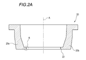
- FIG. 2A is a cross-sectional view obtained by cutting the lip mold 20 along a plane along the central axis A thereof, and FIG. 2B is a partially enlarged view of a region B in FIG. 2A.
- the lip mold 20 is configured to be able to support or release the preform or the wide-mouthed container in accordance with the opening / closing operation of the two split molds 20a and 20b (for example, the movement in the left-right direction in FIG. 2A).
- the lip mold 20 in a state where the two split molds 20a and 20b are closed has a substantially cylindrical shape.
- the lip mold 20 has a holding portion 22 that holds the lip portion of the preform or wide-mouthed container in the closed state.
- FIG. 3 is a cross-sectional view obtained by cutting the preform 30 along a plane along the central axis C thereof.
- the preform 30 includes a first bottom portion 32, a first body portion 34 connected to the first bottom portion 32, and a cylindrical wide-mouthed first lip portion 36 connected to the first body portion 34 on the opposite side of the first bottom portion 32. It is a bottomed resin molded product having.
- the diameter D of the first lip portion 36 may be, for example, 65 mm or more and 110 mm or less, preferably 80 mm or more and 95 mm or less.
- the first lip portion 36 is a portion held by the holding portion 22 (see FIG.
- the length L1 of the first lip portion 36 in the central axis C direction may be, for example, 8.0 mm or more and 15 mm or less.
- the length L2 of the first lip portion 36 held in contact with the lip mold 20 in the central axis C direction may be short, for example, 4.0 mm or more and 7.0 mm or less, and about 5 mm (4.5 mm or more). It may be 5.5 mm or less).
- the outer shapes of the first lip portion 36 and the first body portion 34 are circular in top view or in a horizontal cross section.
- the length L along the central axis C of the preform 30 is, for example, 30 mm or more and 60 mm or less, and may be shorter than the diameter D of the first lip portion.
- the first lip portion 36 includes an annular flange portion 37 provided on an edge located on the opposite side of the first body portion 34 and projecting outward.
- the preform 30 includes an annular overhanging portion 38 that is provided on the outer peripheral portion of the first lip portion 36 that is closer to the first body portion 34 than the flange portion 37 and projects outward.
- the flange portion 37 and the overhanging portion 38 are formed over the circumferential direction of the first lip portion.
- the length of the flange portion 37 protruding outward may be shorter than the length of the first lip portion 36 in the central axis C direction.
- the length L3 protruding to the outside of the flange portion 37 may be, for example, 1.0 mm or more and 3.0 mm or less, more preferably 1.5 mm or more and 2.5 mm or less.
- the length overhanging the outside of the overhanging portion 38 may be shorter than the length overhanging the outside of the flange portion 37.
- the length L4 overhanging the outside of the overhanging portion 38 may be, for example, 0.3 mm or more and 1.5 mm or less, more preferably 0.4 mm or more and 0.6 mm or less.
- the thickness Th1 of the first bottom portion 32 may be 1.5 mm or more and 2.0 mm or less.
- the ratio Th2 / Th1 of the thickness of the first body 34 (maximum thickness of the first body 34) Th2 to the thickness Th1 of the first bottom 32 is 0.8 or more and 1.4 or less, more preferably 0.95 or more. It may be 25 or less.
- the inclination ⁇ of the first body portion 34 with respect to the central axis C is 20 ° or more and 70. It may be ° or less, and may be 30 ° or more and 50 ° or less.
- the shape of the cross section of the preform may be substantially triangular or substantially trapezoidal.
- the holding portion 22 of the lip mold 20 has a lip outer peripheral defining portion 24 that defines an outer peripheral portion of the first lip portion 36 of the preform 30 excluding the flange portion 37 when molding the preform 30 in the injection molding portion 11. ..
- the lip outer peripheral defining portion 24 has a recess 26 that defines an overhanging portion 38 of the preform 30 when molding the preform 30 in the injection molding portion 11.
- FIG. 4 is a schematic cross-sectional view showing an aspect of the injection molding unit 11.
- the injection molding unit 11 includes an injection molding die including an injection core mold 114 and an injection cavity mold 112.
- the injection molding unit 11 is formed by molding the injection core mold 114, the injection cavity mold 112, and the lip mold 20 into a space in the shape of the preform 30, which is formed by molding the injection core mold 114, the injection cavity mold 112, and the lip mold 20 through the runner 116 and the gate 118.
- the preform 30 is injection-molded by pouring a synthetic resin material such as PET: polyethylene terephthalate (by filling with a molten resin).
- a cooling medium having a temperature of 5 ° C. to 20 ° C. is flowed inside the injection core type 114 and the injection cavity type 112, and the temperature is kept low during molding.
- FIG. 5 is a schematic cross-sectional view showing an aspect of the temperature control unit 12.
- the temperature control unit 12 airtightly contacts the cavity type (temperature control cavity type) 122 for accommodating the preform 30 and the preform 30 to preform the air for performing the temperature control blow (cooling blow).
- a mold unit including an air introduction member 124 to be sent to the inside of the 30 is provided.
- the cavity type 122 has a fixed type (single unit type) structure that defines a space having substantially the same shape as the preform 30 manufactured by the injection molding unit 11.
- a temperature control medium (cooling medium) of 20 ° C. to 100 ° C., more preferably 60 ° C. to 90 ° C. flows inside the cavity type 122 to keep the temperature low.
- the air introduction member 124 is composed of a rod member 124a which is hollow and has an air flow hole inside, and a fitting core (blow core member for the temperature control portion) 124b.
- the rod member 124a is housed inside the fitting core 124b so as to be vertically movable.
- An inner flow port 126a capable of ejecting or sucking air is provided at the tip of the rod member 124a.
- the temperature of the air is appropriately set according to the wall thickness of the preform 30 and the wide-mouthed container 40.
- the fitting core 124b is configured to fit (close) the first lip portion 36 when the air introduction member 124 is inserted into the preform 30 (when abutted in an airtight manner).
- the gap between the rod member 124a and the fitting core 124b is an air flow path for supplying and discharging air to the preform 30.
- the gap formed by the tip of the fitting core 124b and the rod member 124a constitutes the outer flow port 126b capable of ejecting or sucking air.
- the inner distribution port 126a and the outer distribution port 126b can serve as an air outlet and an outlet, respectively.
- the temperature control unit 12 is a method of sandwiching the preform between the temperature control cavity type and the temperature control core type (temperature control rod type) in place of or in combination with the above method, various infrared heater types, RED type, and electromagnetic wave heating.
- a temperature control means such as a formula can be adopted.
- the temperature control unit 12 may be omitted.
- the wall thickness distribution of the wide-mouthed container can be improved.
- it is preferable from the viewpoint of manufacturing efficiency to adopt a method in which air is circulated inside the preform in a state where the preform is in contact with the temperature control cavity type described above to cool the preform both inside and outside at the same time. Further, when this method is adopted, it is preferable that the cooling strength of the outer temperature control cavity type is stronger than the cooling strength of the inner air.
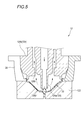
- FIG. 6 is a schematic cross-sectional view showing an aspect of the blow molding unit 13.
- the blow molding unit 13 includes a drawing rod 132, a blow core type 134, a blow cavity type 136, and a blow bottom type 138.
- the blow molding unit 13 stretches the injection-molded preform 30 with, for example, a drawing rod 132, and introduces air from the blow core mold 134 to form the preform 30 into a shape defined by the blow cavity mold 136 and the blow bottom mold 138. It is configured so that it can be inflated to form a wide-mouthed container.
- FIG. 7 is a side view of the wide-mouthed container 40.
- the wide-mouthed container 40 has a second bottom portion 42, a second body portion 44 connected to the second bottom portion 42, and a cylindrical wide-mouthed second lip portion (opening) connected to the second body portion 44 on the opposite side of the second bottom portion 42.
- Part 46 and a cup-shaped container having.
- the second lip portion 46 includes an annular flange portion 47 provided on an edge located on the opposite side of the second body portion 44 and projecting outward, and a second lip portion 47 closer to the second body portion 44 than the flange portion 47.
- the outer diameter of the flange portion 47 of the second lip portion 46 is the maximum diameter of the wide-mouthed container 40.
- the longitudinal stretching ratio (SVR) of the wide-mouthed container 40 with respect to the preform 30 may be 4.0 or more and 6.0 or less.
- the diameter of the second lip portion 46, the flange portion 47, and the overhanging portion 48 of the wide-mouthed container 40 are the same as those of the first lip portion 36, the flange portion 37, and the overhanging portion 38 of the preform 30, respectively.
- the length L1'of the second lip portion 46 of the wide-mouthed container 40 may be longer than the length L1 of the first lip portion 36 by stretching the first lip portion 36 of the preform 30 in the blow molding step.
- a parting line of the lip mold 20 is formed on the second lip portion 46. More specifically, the first lip portion 36 and the second lip portion 46 have vertical parting lines extending in the vertical direction as traces of the contact surfaces of the split molds 20a and 20b constituting the lip mold 20. Two, one annular parting line extending in the circumferential direction is formed as a trace of the contact surface between the lip mold 20 and the injection cavity mold 112.
- the manufacturing method includes an injection molding step of injection molding the preform 30, a temperature control step of adjusting the temperature of the injection molded preform 30 to an appropriate temperature in blow molding, and a wide mouth container 40 by blow molding the preform 30. It is a hot parison type method having a blow molding step of molding.
- the molten resin is injected through the runner 116 and the gate 118 into the space in the shape of the preform 30 formed by molding the injection core mold 114, the injection cavity mold 112, and the lip mold 20.
- the injection core mold 114 and the lip mold 20 are pulled up, and the preform 30 is released from the injection cavity mold 112.
- the overhanging portion 38 of the preform 30 is engaged with the recess 26 (see FIG. 2B) of the lip mold 20. Further, the flange portion 37 of the preform 30 is caught by the holding portion 22 of the lip mold 20.
- the first lip portion 36 is held by the lip mold 20 to release the preform 30 from the injection cavity mold 112.
- the preform 30 is released at a high temperature.
- the cooling time in the injection molding die from the completion of injection of the molten resin to the release of the preform 30 is, for example, 0.0 to 1. It may be .5 seconds.
- injection of molten resin refers to a resin filling process including a pressure holding process. The time of the resin filling step may be, for example, 2.5 to 4.5 seconds.
- a predetermined time until the released preform 30 is conveyed to the temperature control step when the preform 30 is released from the injection molding die at a high temperature, for example, outside the preform 30 after the release. It may be a time (for example, 2.0 to 6.0 seconds) in which the surface temperature rises sharply to about 110 ° C. or higher and 140 ° C. or lower.
- the temperature of the preform 30 molded in the injection molding step is adjusted to an appropriate temperature in blow molding in the temperature control section 12 described above (FIG. 5).
- the preform 30 is housed in the preform-shaped space of the cavity type 122.
- the air introduction member 124 is inserted into the preform 30 housed in the cavity type 122 (contacts airtightly).
- the inner distribution port 126a is opened, and while introducing air from the inner distribution port 126a, a cooling blow (cooling blow) is performed to discharge the air to the outside of the preform 30 via the outer distribution port 126b. ..
- the preform 30 is cooled from the inside by the convection of the air flowing inside. Further, since the preform 30 continues to be in contact with the cavity type 122, it is cooled from the outside to adjust the temperature, and the uneven temperature generated during injection molding is also reduced.
- the temperature control step may be omitted, for example, by adopting the temperature control section 12, the wall thickness distribution of the wide-mouthed container can be improved.
- the preform 30 is molded at a high temperature in the injection molding process, the preform 30 is cooled to a predetermined temperature by cooling air or the like in the temperature control step, and the preform 30 is delivered to, for example, the temperature control section 12.
- the outer surface temperature of the above may be lowered by about 30 ° C. or higher and 50 ° C. or lower.
- a cooling rod piece that contacts the inner surface of the first bottom portion 32 of the preform 30 may be attached to the tip of the rod member 124a.
- the preform 30 is housed in the cavities defined by the blow cavity type 136 and the blow bottom type 138 corresponding to the shape of the wide-mouthed container 40 (see FIG. 7), and then the preform 30 is optionally placed.
- the wide-mouthed container 40 is manufactured by inflating the preform 30 by introducing blow air from the blow core mold 134 while stretching with the stretching rod 132 (FIG. 6). After that, the wide-mouthed container 40 is opened from the mold of the blow molding section 13, and the wide-mouthed container 40 is conveyed to the take-out section 14 to take out the container.
- the wide-mouthed container 40 is manufactured by the above procedure.
- the wide-mouthed container that can be manufactured by the manufacturing method of the present embodiment is not limited to the specific wide-mouthed container 40 shown in FIG. 7.
- the first lip portion 36 of the preform 30 and the second lip portion 46 of the wide-mouthed container 40 described in the present embodiment correspond to each other, and the lengths of these lip portions in the central axis C direction of the preform 30 are short. Therefore, it is easy to come off from the lip mold 20 when it is released from the mold in the injection molding process.
- the preform 30 is injection molded so that the first lip portion 36 of the preform 30 includes the overhanging portion 38.
- the overhanging portion 38 of the preform 30 can be engaged with the recess 26 of the lip mold 20 to prevent the preform 30 from coming off (FIGS. 2B and 4).
- the wide-mouthed container 40 can be suitably manufactured.
- the stretching ratio in the vertical direction with respect to the preform 30 of the wide-mouthed container 40 described in the present embodiment is large, and therefore the wall thickness distribution of the body portion in the vertical direction tends to be uneven.
- whitening is likely to occur in the portion around the gate in the injection molding of the second bottom portion 42 of the wide-mouthed container 40.
- the preform 30 is attached to the first bottom portion.
- the thickness Th1 of the 32 is 1.5 mm or more, or the ratio of the thickness Th1 of the first bottom portion 32 to the thickness Th2 of the first body portion 34 is 0.8 or more (see FIG. 3), and the thickness of the first lip portion 36
- the inclination of the first body portion 34 with respect to the central axis C is 20 ° or more and 70 ° or less (see FIG. 3).
- the thickness Th1 of the first bottom portion 32 of the preform 30 is 1.4 mm and the thickness Th2 of the first body portion 34 is 2.0 mm, it occurs around the gate. While the whitening of the wide-mouthed container 40 was slightly confirmed, when the thickness Th1 of the first bottom 32 of the preform 30 was 1.8 mm and the thickness Th2 of the first body 34 was 2.0 mm, the gate It was found that whitening of the wide-mouthed container 40 generated around the container hardly occurred and showed high transparency.
- the reason for this is that by widening the distance between the gate 118 and the bottom of the injection core mold 114, the resin resistance when the molten resin flows in is reduced, the shear heat generation is reduced, and the preform 30 after molding is the first. It is considered that the abnormally high temperature state of the one bottom portion 32 was suppressed, and as a result, the whitening (crystallization) of the first bottom portion 32 due to the slow cooling was suppressed. Further, by making the first body portion 34 of the preform 30 thicker than before, sufficient heat retention is secured before blow molding even after cooling by the temperature control process of the high-speed ISBM method, and the wide-mouthed container 40 It is probable that it was effective in improving the uneven thickness of the 44th part of the second body.
- the surface roughness of the inner surface and the outer surface of the wide-mouthed container 40 is made different by roughening the cavity surface of the temperature control cavity type or the blow cavity type. May be good. As a result, when the wide-mouthed containers 40 are stacked or separated from each other, the resistance between the wide-mouthed containers 40 is reduced and the handleability can be improved.
- the present invention is not limited to the above-described embodiment, and can be freely modified, improved, and the like as appropriate.
- the material, shape, size, numerical value, form, number, arrangement location, etc. of each component in the above-described embodiment are arbitrary and are not limited as long as the present invention can be achieved.
- the injection core mold, injection cavity mold, and lip mold are molded so that an outwardly projecting portion is formed on the outer peripheral portion of the first lip portion closer to the first body portion than the flange portion.
- the molten resin is injected into the space in the shape of the preform formed by the injection, and the preform is injection-molded.
- a method for manufacturing a wide-mouthed resin container, in which the first lip portion having the overhanging portion is held by the lip mold provided with a recess for engaging with the overhanging portion, and the preform is released from an injection molding die. .. [2] Between the injection molding step and the blow molding step, a temperature control step of adjusting the temperature of the injection molded preform to an appropriate temperature in blow molding is further provided.
- a plane along the central axis of the first lip portion so that the thickness of the first bottom portion is 1.5 mm or more or the ratio of the thickness of the first bottom portion to the thickness of the first body portion is 0.8 or more.
- the inclination of the first body portion with respect to the central axis is 20 ° or more and 70 ° or less.
- a resin wide-mouthed container having a second bottom portion, a second body portion connected to the second bottom portion, and a cylindrical wide-mouthed second lip portion connected to the second body portion on the side opposite to the second bottom portion.
- the lip portion includes an injection molding portion for injecting a resin bottomed preform, which is provided on an edge located on the opposite side of the first body portion and has a flange portion protruding outward.
- a hot parison type resin wide-mouthed container manufacturing apparatus having at least a blow-molded portion for producing a resin wide-mouthed container by blow-molding the injection-molded preform.
- the injection molding unit is configured to inject molten resin into a space in the shape of the preform formed by molding an injection core mold, an injection cavity mold, and a lip mold to inject mold the preform.
- the lip mold has a lip outer peripheral defining portion that defines an outer peripheral portion of the first lip portion of the preform excluding the flange portion.
- the lip outer peripheral defining portion is a resin wide-mouth container manufacturing apparatus having a recess that defines an overhanging portion that projects outward from the outer peripheral portion of the first lip portion that is closer to the first body portion than the flange portion.
- a resin wide-mouthed container having a bottom portion, a body portion connected to the bottom portion, and a cylindrical wide-mouthed lip portion connected to the body portion on the side opposite to the bottom portion.
- the lip portion is provided on an edge located on the opposite side of the bottom portion and projects outward, and is provided on an outer peripheral portion of the lip portion closer to the body portion than the flange portion and faces outward. Equipped with an overhanging part
- the outer diameter of the lip portion is the maximum diameter in the wide-mouthed container. Wide-mouthed resin container.
Abstract
This method for manufacturing a resin wide-mouthed container includes at least: an injection molding step for injection-molding a bottomed preform (30) made of resin; and a blow molding step for manufacturing a resin wide-mouthed container by blow-molding the injection-molded preform (30). In the injection molding step, the preform (30) is injection-molded such that an overhanging section (38) overhanging outward is formed on an outer peripheral section of a first lip section (36) closer to a first body section (34) than a flange section (37), and while the first lip section (36), which is provided with the overhanging section (38), is held by a lip mold (20), which has a recessed section that engages with the overhanging section (38), the preform (30) is separated from an injection molding die.
Description
本発明は、樹脂製広口容器の製造方法、製造装置および樹脂製広口容器に関する。
The present invention relates to a method for manufacturing a resin wide-mouthed container, a manufacturing apparatus, and a resin wide-mouthed container.
特許文献1には、シート材料から形成されたカップ状ポリエステル容器が開示されている。特許文献2には、コールドパリソン方式による二軸延伸ブロー成形法により製造されたプラスチック製の広口容器が開示されている。特許文献3には、ポリエチレンテレフタレート(PET)を延伸ブローして成形した包装用カップ容器が開示されている。
Patent Document 1 discloses a cup-shaped polyester container formed from a sheet material. Patent Document 2 discloses a plastic wide-mouthed container manufactured by a biaxial stretching blow molding method based on a cold parison method. Patent Document 3 discloses a packaging cup container formed by stretching and blowing polyethylene terephthalate (PET).
シート材料から広口容器を成形する方法では、シート材料のコストが一般的に高く、また真空成形やプレス成形の後にトリミング等の後加工をする必要がある。さらに、シート材料を用いる成形方法では容器自体に傷が残りやすく、外観に優れた広口容器を成形することが難しい。また、コールドパリソン方式の二軸延伸ブロー成形法により広口容器を成形する方法では、外表面に多少の擦り傷は生ずるものの上記方法より外観に優れた広口容器を製造可能だが、設備コストが高くなる。
In the method of molding a wide-mouthed container from a sheet material, the cost of the sheet material is generally high, and it is necessary to perform post-processing such as trimming after vacuum forming or press molding. Further, the molding method using a sheet material tends to leave scratches on the container itself, and it is difficult to mold a wide-mouthed container having an excellent appearance. Further, in the method of molding a wide-mouthed container by a cold parison type biaxial stretching blow molding method, a wide-mouthed container having a better appearance than the above method can be manufactured although some scratches occur on the outer surface, but the equipment cost is high.
一方でホットパリソン式の延伸ブロー成形方法(ISBM法)では、1つの製造工程において、容器のプリフォームの射出成形と、当該プリフォームの延伸ブロー成形とを実行できる。ISBM法において製造時間を短縮することができれば、コストを低減しつつ外観に優れた容器を提供することができる。ISBM法における製造時間の短縮の手段としては、国際公開第2019/078358号に開示されたように、射出成形工程においてプリフォームを高温の状態で離型する方法がある。しかし、ISBM法を採用して広口容器を製造すると、射出成形工程においてプリフォームを射出キャビティ型や射出コア型から離型する際にプリフォームがネック型から外れやすいことがわかった。
On the other hand, in the hot parison type stretch blow molding method (ISBM method), injection molding of the preform of the container and stretch blow molding of the preform can be executed in one manufacturing process. If the manufacturing time can be shortened in the ISBM method, it is possible to provide a container having an excellent appearance while reducing the cost. As a means for shortening the production time in the ISBM method, as disclosed in International Publication No. 2019/078358, there is a method of releasing the preform in a high temperature state in the injection molding process. However, when a wide-mouthed container is manufactured by adopting the ISBM method, it has been found that the preform is likely to come off from the neck mold when the preform is released from the injection cavity type or the injection core type in the injection molding process.
本発明は、広口容器を好適に製造できる樹脂製広口容器の製造方法および製造装置ならびに新規な樹脂製広口容器を提供することを目的とする。
An object of the present invention is to provide a method and an apparatus for manufacturing a resin wide-mouthed container capable of suitably manufacturing a wide-mouthed container, and a novel resin wide-mouthed container.
本発明の一側面に係る樹脂製広口容器の製造方法は、
第一底部と、前記第一底部に連なる第一胴部と、前記第一底部と反対側で前記第一胴部に連なる円筒形状の広口の第一リップ部と、を有し、前記第一リップ部は前記第一胴部と反対側に位置する縁に設けられて外側に向かって張り出したフランジ部を備える、樹脂製の有底のプリフォームを射出成形する射出成形工程と、
射出成形された前記プリフォームをブロー成形して樹脂製広口容器を製造するブロー成形工程と、を少なくとも有するホットパリソン式の樹脂製広口容器の製造方法であって、
前記射出成形工程において、
前記フランジ部より前記第一胴部に近い前記第一リップ部の外周部に外側に向かって張り出した張出部が形成されるように、射出コア型、射出キャビティ型およびリップ型を型締めすることで形成される前記プリフォームの形状の空間に溶融樹脂を射出して、前記プリフォームを射出成形し、
前記張出部を備える前記第一リップ部を前記張出部に係合する凹部を備える前記リップ型により保持して射出成形金型から前記プリフォームを離型する、樹脂製広口容器の製造方法である。 The method for manufacturing a resin wide-mouthed container according to one aspect of the present invention is as follows.
It has a first bottom portion, a first body portion connected to the first bottom portion, and a cylindrical wide-mouthed first lip portion connected to the first body portion on the side opposite to the first bottom portion. An injection molding step of injecting a resin-bottomed preform, wherein the lip portion is provided on an edge located on the opposite side of the first body portion and has a flange portion protruding outward.
A method for manufacturing a hot parison type resin wide-mouthed container, which comprises at least a blow molding step of blowing-molding the injection-molded preform to manufacture a resin wide-mouthed container.
In the injection molding process
The injection core mold, injection cavity mold, and lip mold are molded so that an outwardly projecting portion is formed on the outer peripheral portion of the first lip portion closer to the first body portion than the flange portion. The molten resin is injected into the space in the shape of the preform formed by the injection, and the preform is injection-molded.
A method for manufacturing a wide-mouthed resin container, in which the first lip portion having the overhanging portion is held by the lip mold provided with a recess for engaging with the overhanging portion, and the preform is released from an injection molding die. Is.
本発明の一側面に係る樹脂製広口容器の製造装置は、
第一底部と、前記第一底部に連なる第一胴部と、前記第一底部と反対側で前記第一胴部に連なる円筒形状の広口の第一リップ部と、を有し、前記第一リップ部は前記第一胴部と反対側に位置する縁に設けられて外側に向かって張り出したフランジ部を備える、樹脂製の有底のプリフォームを射出成形する射出成形部と、
射出成形された前記プリフォームをブロー成形して樹脂製広口容器を製造するブロー成形部と、を少なくとも有するホットパリソン式の樹脂製広口容器の製造装置であって、
前記射出成形部は、射出コア型、射出キャビティ型およびリップ型を型締めすることで形成される前記プリフォームの形状の空間に溶融樹脂を射出して、前記プリフォームを射出成形するように構成されており、
前記リップ型は前記プリフォームの前記第一リップ部の前記フランジ部を除く外周部を規定するリップ外周規定部を有し、
前記リップ外周規定部は前記フランジ部より前記第一胴部に近い前記第一リップ部の外周部に外側に向かって張り出す張出部を規定する凹部を有する、樹脂製広口容器の製造装置である。 The resin wide-mouthed container manufacturing apparatus according to one aspect of the present invention is
It has a first bottom portion, a first body portion connected to the first bottom portion, and a cylindrical wide-mouthed first lip portion connected to the first body portion on the side opposite to the first bottom portion. The lip portion includes an injection molding portion for injecting a resin bottomed preform, which is provided on an edge located on the opposite side of the first body portion and has a flange portion protruding outward.
A hot parison type resin wide-mouthed container manufacturing apparatus having at least a blow-molded portion for producing a resin wide-mouthed container by blow-molding the injection-molded preform.
The injection molding unit is configured to inject molten resin into a space in the shape of the preform formed by molding an injection core mold, an injection cavity mold, and a lip mold to inject mold the preform. Has been
The lip mold has a lip outer peripheral defining portion that defines an outer peripheral portion of the first lip portion of the preform excluding the flange portion.
The lip outer peripheral defining portion is a resin wide-mouth container manufacturing apparatus having a recess that defines an overhanging portion that projects outward from the outer peripheral portion of the first lip portion that is closer to the first body portion than the flange portion. be.
本発明の一側面に係る樹脂製広口容器は、
底部と、前記底部に連なる胴部と、前記底部と反対側で前記胴部に連なる円筒形状の広口のリップ部と、を有する樹脂製広口容器であって、
前記リップ部は、前記底部と反対側に位置する縁に設けられて外側に向かって張り出したフランジ部と、前記フランジ部より前記胴部に近い前記リップ部の外周部に設けられて外側に向かって張り出した張出部と、を備え、
前記リップ部の外径が前記広口容器における最大径である、
樹脂製広口容器である。 The resin wide-mouthed container according to one aspect of the present invention
A resin wide-mouthed container having a bottom portion, a body portion connected to the bottom portion, and a cylindrical wide-mouthed lip portion connected to the body portion on the side opposite to the bottom portion.
The lip portion is provided on an edge located on the opposite side of the bottom portion and projects outward, and is provided on an outer peripheral portion of the lip portion closer to the body portion than the flange portion and faces outward. Equipped with an overhanging part
The outer diameter of the lip portion is the maximum diameter in the wide-mouthed container.
It is a resin wide-mouthed container.
本発明によれば、広口容器を好適に製造できる樹脂製広口容器の製造方法および製造装置ならびに新規な樹脂製広口容器を提供できる。
According to the present invention, it is possible to provide a method and an apparatus for manufacturing a resin wide-mouthed container capable of suitably manufacturing a wide-mouthed container, and a novel resin wide-mouthed container.
以下、本発明の実施形態について、図面を参照して説明する。尚、本図面に示された各部材の寸法は、説明の便宜上、実際の各部材の寸法とは異なる場合がある。
Hereinafter, embodiments of the present invention will be described with reference to the drawings. The dimensions of each member shown in this drawing may differ from the actual dimensions of each member for convenience of explanation.
まず、図1を参照して、樹脂製広口容器の製造装置10について説明する。図1は製造装置10の機能ブロック図である。
First, the resin wide-mouthed container manufacturing apparatus 10 will be described with reference to FIG. FIG. 1 is a functional block diagram of the manufacturing apparatus 10.
図1に示すように、製造装置10は、樹脂製広口容器のプリフォームを製造するための射出成形部11と、製造されたプリフォームの温度を調整するための温調部12と、プリフォームをブローして容器を製造するためのブロー成形部(ブロー装置の一例)13と、製造された容器を取り出すための取出部14と、を備えるホットパリソン式の装置である。射出成形部11には、原材料である樹脂材料を供給する射出装置15が接続されている。
As shown in FIG. 1, the manufacturing apparatus 10 includes an injection molding section 11 for manufacturing a preform of a resin wide-mouthed container, a temperature control section 12 for adjusting the temperature of the manufactured preform, and a preform. This is a hot parison type device including a blow molding section (an example of a blow device) 13 for manufacturing a container by blowing the container, and a take-out section 14 for taking out the manufactured container. An injection device 15 for supplying a resin material as a raw material is connected to the injection molding unit 11.
射出成形部11と温調部12とブロー成形部13と取出部14とは、搬送手段16を中心として所定角度(本実施形態では90度)ずつ回転した位置に設けられている。搬送手段16は回転板等で構成されている。搬送手段16は、後述する図2Aおよび図2Bに示す搬送手段16に取付けられているリップ型20によりプリフォーム又は広口容器を支持して、回転板の回転に伴ってプリフォーム又は広口容器を各部に搬送するように構成されている。
The injection molding unit 11, the temperature control unit 12, the blow molding unit 13, and the take-out unit 14 are provided at positions rotated by a predetermined angle (90 degrees in this embodiment) about the transport means 16. The transport means 16 is composed of a rotating plate or the like. The transporting means 16 supports the preform or the wide-mouthed container by the lip mold 20 attached to the transporting means 16 shown in FIGS. 2A and 2B, which will be described later, and each part of the preform or the wide-mouthed container is supported by the rotation of the rotating plate. It is configured to be transported to.
ここで図2A及び図2Bを参照して、リップ型20を説明する。図2Aはリップ型20をその中心軸線Aに沿う平面で切断して得られる断面図であり、図2Bは図2Aにおける領域Bの部分拡大図である。リップ型20は2つの割型20a,20bの開閉動作(例えば図2Aにおける左右方向への移動)に伴いプリフォーム又は広口容器を支持または解放可能に構成されている。2つの割型20a,20bが閉じた状態におけるリップ型20は略円筒形状である。リップ型20は閉じた状態においてプリフォーム又は広口容器のリップ部を保持する保持部22を有する。
Here, the lip type 20 will be described with reference to FIGS. 2A and 2B. FIG. 2A is a cross-sectional view obtained by cutting the lip mold 20 along a plane along the central axis A thereof, and FIG. 2B is a partially enlarged view of a region B in FIG. 2A. The lip mold 20 is configured to be able to support or release the preform or the wide-mouthed container in accordance with the opening / closing operation of the two split molds 20a and 20b (for example, the movement in the left-right direction in FIG. 2A). The lip mold 20 in a state where the two split molds 20a and 20b are closed has a substantially cylindrical shape. The lip mold 20 has a holding portion 22 that holds the lip portion of the preform or wide-mouthed container in the closed state.
ここで、図3を参照して本実施形態の製造装置10により成形されるプリフォーム30について説明する。図3は、プリフォーム30をその中心軸線Cに沿う平面で切断して得られる断面図である。プリフォーム30は、第一底部32と、第一底部32に連なる第一胴部34と、第一底部32と反対側で第一胴部34に連なる円筒形状の広口の第一リップ部36と、を有する有底の樹脂成形品である。第一リップ部36の直径Dは、例えば、65mm以上110mm以下、好ましくは80mm以上95mm以下としてもよい。第一リップ部36はリップ型20の保持部22(図2A参照)により保持される部分である。第一リップ部36の中心軸線C方向の長さL1は、例えば、8.0mm以上15mm以下としても良い。このうち、リップ型20に当接して保持される第一リップ部36の中心軸線C方向の長さL2は短く、例えば4.0mm以上7.0mm以下としてもよく、5mm程度(4.5mm以上5.5mm以下)としてもよい。また、第一リップ部36および第一胴部34の外形は、上面視または水平断面で円形状である。また、プリフォーム30の中心軸線Cに沿った長さLは、例えば、例えば、30mm以上60mm以下であり、第一リップ部の直径Dより短くてもよい。
Here, the preform 30 formed by the manufacturing apparatus 10 of the present embodiment will be described with reference to FIG. FIG. 3 is a cross-sectional view obtained by cutting the preform 30 along a plane along the central axis C thereof. The preform 30 includes a first bottom portion 32, a first body portion 34 connected to the first bottom portion 32, and a cylindrical wide-mouthed first lip portion 36 connected to the first body portion 34 on the opposite side of the first bottom portion 32. It is a bottomed resin molded product having. The diameter D of the first lip portion 36 may be, for example, 65 mm or more and 110 mm or less, preferably 80 mm or more and 95 mm or less. The first lip portion 36 is a portion held by the holding portion 22 (see FIG. 2A) of the lip mold 20. The length L1 of the first lip portion 36 in the central axis C direction may be, for example, 8.0 mm or more and 15 mm or less. Of these, the length L2 of the first lip portion 36 held in contact with the lip mold 20 in the central axis C direction may be short, for example, 4.0 mm or more and 7.0 mm or less, and about 5 mm (4.5 mm or more). It may be 5.5 mm or less). Further, the outer shapes of the first lip portion 36 and the first body portion 34 are circular in top view or in a horizontal cross section. Further, the length L along the central axis C of the preform 30 is, for example, 30 mm or more and 60 mm or less, and may be shorter than the diameter D of the first lip portion.
第一リップ部36は、第一胴部34と反対側に位置する縁に設けられて外側に向かって張り出した環状のフランジ部37を備える。プリフォーム30は、フランジ部37より第一胴部34に近い第一リップ部36の外周部に設けられて外側に向かって張り出した環状の張出部38を備える。フランジ部37及び張出部38は、第一リップ部の周方向にわたって形成されている。フランジ部37の外側に張り出した長さは、第一リップ部36の中心軸線C方向の長さよりも短くてもよい。フランジ部37の外側に張り出した長さL3は、例えば、1.0mm以上3.0mm以下、より好ましくは1.5mm以上2.5mm以下としてもよい。張出部38の外側に張り出した長さは、フランジ部37の外側に張り出した長さよりも短くてもよい。張出部38の外側に張り出した長さL4は、例えば、0.3mm以上1.5mm以下、より好ましくは0.4mm以上0.6mm以下としてもよい。
The first lip portion 36 includes an annular flange portion 37 provided on an edge located on the opposite side of the first body portion 34 and projecting outward. The preform 30 includes an annular overhanging portion 38 that is provided on the outer peripheral portion of the first lip portion 36 that is closer to the first body portion 34 than the flange portion 37 and projects outward. The flange portion 37 and the overhanging portion 38 are formed over the circumferential direction of the first lip portion. The length of the flange portion 37 protruding outward may be shorter than the length of the first lip portion 36 in the central axis C direction. The length L3 protruding to the outside of the flange portion 37 may be, for example, 1.0 mm or more and 3.0 mm or less, more preferably 1.5 mm or more and 2.5 mm or less. The length overhanging the outside of the overhanging portion 38 may be shorter than the length overhanging the outside of the flange portion 37. The length L4 overhanging the outside of the overhanging portion 38 may be, for example, 0.3 mm or more and 1.5 mm or less, more preferably 0.4 mm or more and 0.6 mm or less.
第一底部32の厚みTh1は1.5mm以上2.0mm以下であってもよい。第一底部32の厚みTh1に対する第一胴部34の厚み(第一胴部34の最大厚み)Th2の比Th2/Th1は0.8以上1.4以下、より好ましくは0.95以上1.25以下であってもよい。第一リップ部36の中心軸線Cに沿う平面でプリフォーム30を切断して得られるプリフォーム30の断面において(図3)、第一胴部34の中心軸線Cに対する傾きθは20°以上70°以下であってもよく、30°以上50°以下であってもよい。プリフォームの当該断面の形状は略三角形状または略台形状であってもよい。
The thickness Th1 of the first bottom portion 32 may be 1.5 mm or more and 2.0 mm or less. The ratio Th2 / Th1 of the thickness of the first body 34 (maximum thickness of the first body 34) Th2 to the thickness Th1 of the first bottom 32 is 0.8 or more and 1.4 or less, more preferably 0.95 or more. It may be 25 or less. In the cross section of the preform 30 obtained by cutting the preform 30 along the plane along the central axis C of the first lip portion 36 (FIG. 3), the inclination θ of the first body portion 34 with respect to the central axis C is 20 ° or more and 70. It may be ° or less, and may be 30 ° or more and 50 ° or less. The shape of the cross section of the preform may be substantially triangular or substantially trapezoidal.
ここで、図2A及び図2Bに戻りリップ型20の説明を再開する。リップ型20の保持部22は、射出成形部11においてプリフォーム30を成形する際に、プリフォーム30の第一リップ部36のフランジ部37を除く外周部を規定するリップ外周規定部24を有する。リップ外周規定部24は、射出成形部11においてプリフォーム30を成形する際に、プリフォーム30の張出部38を規定する凹部26を有する。
Here, the explanation of the lip type 20 is resumed by returning to FIGS. 2A and 2B. The holding portion 22 of the lip mold 20 has a lip outer peripheral defining portion 24 that defines an outer peripheral portion of the first lip portion 36 of the preform 30 excluding the flange portion 37 when molding the preform 30 in the injection molding portion 11. .. The lip outer peripheral defining portion 24 has a recess 26 that defines an overhanging portion 38 of the preform 30 when molding the preform 30 in the injection molding portion 11.
続いて図4を参照して射出成形部11を説明する。図4は射出成形部11の態様を表す断面模式図である。射出成形部11は、射出コア型114および射出キャビティ型112を含む射出成形金型を備えている。射出成形部11は、射出コア型114、射出キャビティ型112およびリップ型20が型締めされることで形成されるプリフォーム30の形状の空間に、ランナー116及びゲート118を介してポリエステル系樹脂(例えばPET:ポリエチレンテレフタレート)等の合成樹脂材料を流し込むことにより(溶融樹脂を充填することにより)、プリフォーム30を射出成形するように構成されている。射出コア型114および射出キャビティ型112の内部には、例えば、5℃~20℃の冷却媒体が流されており、成形時は低温に保たれる。
Subsequently, the injection molding unit 11 will be described with reference to FIG. FIG. 4 is a schematic cross-sectional view showing an aspect of the injection molding unit 11. The injection molding unit 11 includes an injection molding die including an injection core mold 114 and an injection cavity mold 112. The injection molding unit 11 is formed by molding the injection core mold 114, the injection cavity mold 112, and the lip mold 20 into a space in the shape of the preform 30, which is formed by molding the injection core mold 114, the injection cavity mold 112, and the lip mold 20 through the runner 116 and the gate 118. For example, the preform 30 is injection-molded by pouring a synthetic resin material such as PET: polyethylene terephthalate (by filling with a molten resin). For example, a cooling medium having a temperature of 5 ° C. to 20 ° C. is flowed inside the injection core type 114 and the injection cavity type 112, and the temperature is kept low during molding.
ここで、図5を参照して図1に示す温調部12を説明する。図5は温調部12の態様を表す断面模式図である。温調部12は、温調ブロー(冷却ブロー)を行うための、プリフォーム30を収容するキャビティ型(温調用キャビティ型)122と、プリフォーム30に気密可能に当接されてエアをプリフォーム30の内部に送るエア導入部材124と、を備える金型ユニットを備えている。
キャビティ型122は、射出成形部11で製造されたプリフォーム30と略同じ形状の空間を規定する、固定式(単一ユニット式)の構造を有している。キャビティ型122の内部には、例えば、20℃~100℃、より好ましくは60℃~90℃の温調媒体(冷却媒体)が流れており、温度を低く保っている。 Here, thetemperature control unit 12 shown in FIG. 1 will be described with reference to FIG. FIG. 5 is a schematic cross-sectional view showing an aspect of the temperature control unit 12. The temperature control unit 12 airtightly contacts the cavity type (temperature control cavity type) 122 for accommodating the preform 30 and the preform 30 to preform the air for performing the temperature control blow (cooling blow). A mold unit including an air introduction member 124 to be sent to the inside of the 30 is provided.
Thecavity type 122 has a fixed type (single unit type) structure that defines a space having substantially the same shape as the preform 30 manufactured by the injection molding unit 11. For example, a temperature control medium (cooling medium) of 20 ° C. to 100 ° C., more preferably 60 ° C. to 90 ° C. flows inside the cavity type 122 to keep the temperature low.
キャビティ型122は、射出成形部11で製造されたプリフォーム30と略同じ形状の空間を規定する、固定式(単一ユニット式)の構造を有している。キャビティ型122の内部には、例えば、20℃~100℃、より好ましくは60℃~90℃の温調媒体(冷却媒体)が流れており、温度を低く保っている。 Here, the
The
エア導入部材124は、中空で内部にエア流通孔が設けられたロッド部材124aと、嵌合コア(温調部用のブローコア部材)124bと、により構成されている。ロッド部材124aは嵌合コア124bの内部に上下動可能に収容されている。ロッド部材124aの先端にはエアを噴出または吸引可能な内方流通口126aが設けられている。エアの温度はプリフォーム30や広口容器40の肉厚に応じ適宜設定される。嵌合コア124bは、エア導入部材124がプリフォーム30に挿入されると(気密可能に当接されると)、第一リップ部36に嵌る(密接する)ように構成されている。これにより、プリフォーム30の内部のエアが第一リップ部36から嵌合コア124bの外側に漏れることを防止できる。ロッド部材124aと嵌合コア124bとの間の隙間は、プリフォーム30に対しエアを給排するためのエア流通経路である。嵌合コア124bの先端とロッド部材124aとが形成する隙間が、エアを噴出または吸引可能な外方流通口126bを構成する。内方流通口126aおよび外方流通口126bは、それぞれ送風口および排出口となり得る。
The air introduction member 124 is composed of a rod member 124a which is hollow and has an air flow hole inside, and a fitting core (blow core member for the temperature control portion) 124b. The rod member 124a is housed inside the fitting core 124b so as to be vertically movable. An inner flow port 126a capable of ejecting or sucking air is provided at the tip of the rod member 124a. The temperature of the air is appropriately set according to the wall thickness of the preform 30 and the wide-mouthed container 40. The fitting core 124b is configured to fit (close) the first lip portion 36 when the air introduction member 124 is inserted into the preform 30 (when abutted in an airtight manner). As a result, it is possible to prevent the air inside the preform 30 from leaking from the first lip portion 36 to the outside of the fitting core 124b. The gap between the rod member 124a and the fitting core 124b is an air flow path for supplying and discharging air to the preform 30. The gap formed by the tip of the fitting core 124b and the rod member 124a constitutes the outer flow port 126b capable of ejecting or sucking air. The inner distribution port 126a and the outer distribution port 126b can serve as an air outlet and an outlet, respectively.
なお、温調部12は、上述の方式に代えてまたは組み合わせて、温調キャビティ型および温調コア型(温調ロッド型)でプリフォームを挟み込む方式、各種赤外線ヒーター式、RED式、電磁波加熱式等の温調手段を採用し得る。なお、温調部12は省略してもよい。例えば温調部12を採用することで広口容器の肉厚分布を改善することができる。ただし、上述の温調キャビティ型にプリフォームを接触させた状態でエアをプリフォームの内部に流通させて、プリフォームを内外同時に冷却させる方式を採用すると、製造効率の観点から好ましい。また、当該方式を採用する場合には、外側の温調キャビティ型による冷却強度を、内側のエアによる冷却強度よりも強くすると好ましい。
In addition, the temperature control unit 12 is a method of sandwiching the preform between the temperature control cavity type and the temperature control core type (temperature control rod type) in place of or in combination with the above method, various infrared heater types, RED type, and electromagnetic wave heating. A temperature control means such as a formula can be adopted. The temperature control unit 12 may be omitted. For example, by adopting the temperature control unit 12, the wall thickness distribution of the wide-mouthed container can be improved. However, it is preferable from the viewpoint of manufacturing efficiency to adopt a method in which air is circulated inside the preform in a state where the preform is in contact with the temperature control cavity type described above to cool the preform both inside and outside at the same time. Further, when this method is adopted, it is preferable that the cooling strength of the outer temperature control cavity type is stronger than the cooling strength of the inner air.
ここで、図6を参照して図1に示すブロー成形部13を説明する。図6は、ブロー成形部13の態様を表す断面模式図である。ブロー成形部13は、延伸ロッド132、ブローコア型134、ブローキャビティ型136、ブロー底型138を備えている。ブロー成形部13は、射出成形されたプリフォーム30を例えば延伸ロッド132で延伸しつつ、ブローコア型134からエアを導入してプリフォーム30をブローキャビティ型136およびブロー底型138が規定する形状に膨らませて、広口容器を成形可能に構成されている。
Here, the blow molding unit 13 shown in FIG. 1 will be described with reference to FIG. FIG. 6 is a schematic cross-sectional view showing an aspect of the blow molding unit 13. The blow molding unit 13 includes a drawing rod 132, a blow core type 134, a blow cavity type 136, and a blow bottom type 138. The blow molding unit 13 stretches the injection-molded preform 30 with, for example, a drawing rod 132, and introduces air from the blow core mold 134 to form the preform 30 into a shape defined by the blow cavity mold 136 and the blow bottom mold 138. It is configured so that it can be inflated to form a wide-mouthed container.
続いて、図7を参照して本実施形態の製造装置10により成形される広口容器40を説明する。図7は広口容器40の側面図である。広口容器40は、第二底部42と、第二底部42に連なる第二胴部44と、第二底部42と反対側で第二胴部44に連なる円筒形状の広口の第二リップ部(開口部)46と、を有するカップ状の容器である。第二リップ部46は、第二胴部44と反対側に位置する縁に設けられて外側に向かって張り出した環状のフランジ部47と、当該フランジ部47より第二胴部44に近い第二リップ部46の外周部に設けられて外側に向かって張り出した環状の張出部48を有する。第二リップ部46のフランジ部47の外径が広口容器40における最大径である。広口容器40のプリフォーム30に対する縦延伸倍率(SVR)は4.0以上6.0以下であってもよい。広口容器40の第二リップ部46の直径、フランジ部47、張出部48のサイズや形状は、プリフォーム30の第一リップ部36、フランジ部37、張出部38とそれぞれ同一である。広口容器40の第二リップ部46の長さL1’は、プリフォーム30の第一リップ部36をブロー成形工程で延伸させ、第一リップ部36の長さL1より長くてもよい。第二リップ部46にはリップ型20のパーティングラインが形成される。より具体的には、第一リップ部36、第二リップ部46には、リップ型20を構成する割型20a,20bの当接面の痕跡として鉛直方向に延びる縦線状のパーティングラインが2つ、リップ型20と射出キャビティ型112の当接面の痕跡として周方向に延びる環状のパーティングラインが1つ、形成される。これらパーティングラインは、リップ型20の保持部22の範囲(プリフォーム30の第一リップ部36の長さL2の範囲)に形成される。また、第二底部42の下面中心領域には、ゲート118からの溶融樹脂の射出痕(横断面が円形状)が形成される。
Subsequently, the wide-mouthed container 40 formed by the manufacturing apparatus 10 of the present embodiment will be described with reference to FIG. 7. FIG. 7 is a side view of the wide-mouthed container 40. The wide-mouthed container 40 has a second bottom portion 42, a second body portion 44 connected to the second bottom portion 42, and a cylindrical wide-mouthed second lip portion (opening) connected to the second body portion 44 on the opposite side of the second bottom portion 42. Part) 46, and a cup-shaped container having. The second lip portion 46 includes an annular flange portion 47 provided on an edge located on the opposite side of the second body portion 44 and projecting outward, and a second lip portion 47 closer to the second body portion 44 than the flange portion 47. It has an annular overhanging portion 48 that is provided on the outer peripheral portion of the lip portion 46 and projects outward. The outer diameter of the flange portion 47 of the second lip portion 46 is the maximum diameter of the wide-mouthed container 40. The longitudinal stretching ratio (SVR) of the wide-mouthed container 40 with respect to the preform 30 may be 4.0 or more and 6.0 or less. The diameter of the second lip portion 46, the flange portion 47, and the overhanging portion 48 of the wide-mouthed container 40 are the same as those of the first lip portion 36, the flange portion 37, and the overhanging portion 38 of the preform 30, respectively. The length L1'of the second lip portion 46 of the wide-mouthed container 40 may be longer than the length L1 of the first lip portion 36 by stretching the first lip portion 36 of the preform 30 in the blow molding step. A parting line of the lip mold 20 is formed on the second lip portion 46. More specifically, the first lip portion 36 and the second lip portion 46 have vertical parting lines extending in the vertical direction as traces of the contact surfaces of the split molds 20a and 20b constituting the lip mold 20. Two, one annular parting line extending in the circumferential direction is formed as a trace of the contact surface between the lip mold 20 and the injection cavity mold 112. These parting lines are formed in the range of the holding portion 22 of the lip mold 20 (the range of the length L2 of the first lip portion 36 of the preform 30). In addition, injection marks of molten resin (circular cross section) from the gate 118 are formed in the lower surface center region of the second bottom portion 42.
続いて、本実施形態に係る広口容器の製造方法について説明する。当該製造方法は、プリフォーム30を射出成形する射出成形工程と、射出成形されたプリフォーム30の温度をブロー成形における適温に調整する温調工程と、プリフォーム30をブロー成形して広口容器40を成形するブロー成形工程と、を有するホットパリソン式の方法である。
Subsequently, the method for manufacturing the wide-mouthed container according to the present embodiment will be described. The manufacturing method includes an injection molding step of injection molding the preform 30, a temperature control step of adjusting the temperature of the injection molded preform 30 to an appropriate temperature in blow molding, and a wide mouth container 40 by blow molding the preform 30. It is a hot parison type method having a blow molding step of molding.
図4を参照して射出成形工程について説明する。射出成形工程では、射出コア型114、射出キャビティ型112およびリップ型20を型締めすることで形成されるプリフォーム30の形状の空間にランナー116およびゲート118を介して溶融樹脂を射出する。所定時間経過後に、射出コア型114およびリップ型20を引き上げ、プリフォーム30を射出キャビティ型112から離型する。この時、プリフォーム30の張出部38はリップ型20の凹部26(図2B参照)に係合している。また、プリフォーム30のフランジ部37はリップ型20の保持部22に引っ掛かる。この状態で、第一リップ部36をリップ型20により保持して射出キャビティ型112からプリフォーム30を離型する。ここで、溶融樹脂の射出が済んでからプリフォーム30を離型するまでの時間を短くするとプリフォーム30が高温の状態で離型される。プリフォーム30を射出成形金型から高温離型する場合においては、溶融樹脂の射出が済んでからプリフォーム30を離型するまでの射出成形金型内での冷却時間を例えば0.0~1.5秒としてもよい。なお、上述の「溶融樹脂の射出」とは保圧工程を含む樹脂充填工程を指す。当該樹脂充填工程の時間としては、例えば2.5~4.5秒としてもよい。また、離型されたプリフォーム30が温調工程に搬送される迄の所定時間としては、プリフォーム30を射出成形金型から高温離型する場合においては、例えば離型後にプリフォーム30の外表面温度が急上昇して110℃以上140℃以下程度となる時間(例えば、2.0~6.0秒)としてもよい。
The injection molding process will be described with reference to FIG. In the injection molding step, the molten resin is injected through the runner 116 and the gate 118 into the space in the shape of the preform 30 formed by molding the injection core mold 114, the injection cavity mold 112, and the lip mold 20. After a lapse of a predetermined time, the injection core mold 114 and the lip mold 20 are pulled up, and the preform 30 is released from the injection cavity mold 112. At this time, the overhanging portion 38 of the preform 30 is engaged with the recess 26 (see FIG. 2B) of the lip mold 20. Further, the flange portion 37 of the preform 30 is caught by the holding portion 22 of the lip mold 20. In this state, the first lip portion 36 is held by the lip mold 20 to release the preform 30 from the injection cavity mold 112. Here, if the time from the injection of the molten resin to the release of the preform 30 is shortened, the preform 30 is released at a high temperature. When the preform 30 is released from the injection molding die at a high temperature, the cooling time in the injection molding die from the completion of injection of the molten resin to the release of the preform 30 is, for example, 0.0 to 1. It may be .5 seconds. The above-mentioned "injection of molten resin" refers to a resin filling process including a pressure holding process. The time of the resin filling step may be, for example, 2.5 to 4.5 seconds. Further, as a predetermined time until the released preform 30 is conveyed to the temperature control step, when the preform 30 is released from the injection molding die at a high temperature, for example, outside the preform 30 after the release. It may be a time (for example, 2.0 to 6.0 seconds) in which the surface temperature rises sharply to about 110 ° C. or higher and 140 ° C. or lower.
温調工程では、射出成形工程で成形されたプリフォーム30の温度を、前述の温調部12においてブロー成形における適温に調整する(図5)。まず、プリフォーム30をキャビティ型122のプリフォーム形状の空間内に収容する。続いて、キャビティ型122に収容されたプリフォーム30の内部にエア導入部材124を挿入する(気密可能に当接する)。そして、内方流通口126aを開栓し、内方流通口126aからエアを導入しつつ、外方流通口126bを介してプリフォーム30の外部にエアを排出する冷却ブロー(クーリングブロー)を行う。この時、内方流通口126aからエアが噴出し続けているため、プリフォーム30は内部を流れるエアの対流により、内側から冷却される。また、プリフォーム30はキャビティ型122と接触し続けるため、外側からも冷却されて温度調整され、さらに、射出成形時に生じた偏温も低減される。
In the temperature control step, the temperature of the preform 30 molded in the injection molding step is adjusted to an appropriate temperature in blow molding in the temperature control section 12 described above (FIG. 5). First, the preform 30 is housed in the preform-shaped space of the cavity type 122. Subsequently, the air introduction member 124 is inserted into the preform 30 housed in the cavity type 122 (contacts airtightly). Then, the inner distribution port 126a is opened, and while introducing air from the inner distribution port 126a, a cooling blow (cooling blow) is performed to discharge the air to the outside of the preform 30 via the outer distribution port 126b. .. At this time, since the air continues to be ejected from the inner distribution port 126a, the preform 30 is cooled from the inside by the convection of the air flowing inside. Further, since the preform 30 continues to be in contact with the cavity type 122, it is cooled from the outside to adjust the temperature, and the uneven temperature generated during injection molding is also reduced.
なお、温調工程は省略してもよいが、例えば温調部12を採用することで広口容器の肉厚分布を改善することができる。また、射出成形工程においてプリフォーム30を高温離型した場合には、温調工程において冷却エア等でプリフォーム30を所定温度に冷却して、例えば温調部12へ搬入した時点からプリフォーム30の外表面温度を30℃以上50℃以下程度で下げてもよい。射出成形工程においてプリフォーム30を高温離型して温調工程で冷却することで、サイクル時間を短縮しつつ外観に優れる広口容器40を成形できる。また、温調工程では、プリフォーム30の第一底部32の内面に接触するクーリングロッドピースをロッド部材124aの先端に付設してもよい。
Although the temperature control step may be omitted, for example, by adopting the temperature control section 12, the wall thickness distribution of the wide-mouthed container can be improved. Further, when the preform 30 is molded at a high temperature in the injection molding process, the preform 30 is cooled to a predetermined temperature by cooling air or the like in the temperature control step, and the preform 30 is delivered to, for example, the temperature control section 12. The outer surface temperature of the above may be lowered by about 30 ° C. or higher and 50 ° C. or lower. By releasing the preform 30 at a high temperature in the injection molding step and cooling it in the temperature control step, it is possible to mold the wide-mouthed container 40 having an excellent appearance while shortening the cycle time. Further, in the temperature control step, a cooling rod piece that contacts the inner surface of the first bottom portion 32 of the preform 30 may be attached to the tip of the rod member 124a.
ブロー成形工程では、広口容器40(図7参照)の形状に対応したブローキャビティ型136およびブロー底型138が規定するキャビティにプリフォーム30を収容し、続いて、任意選択的にプリフォーム30を延伸ロッド132によって延伸させつつ、ブローコア型134からブローエアを導入することでプリフォーム30を膨らませて広口容器40を製造する(図6)。その後、ブロー成形部13の金型から広口容器40を開放して、取出部14へ広口容器40を搬送して容器を取り出す。以上の手順によって、広口容器40が製造される。なお、本実施形態の製造方法において製造できる広口容器は図7に示される特定の広口容器40に限定されない。
In the blow molding step, the preform 30 is housed in the cavities defined by the blow cavity type 136 and the blow bottom type 138 corresponding to the shape of the wide-mouthed container 40 (see FIG. 7), and then the preform 30 is optionally placed. The wide-mouthed container 40 is manufactured by inflating the preform 30 by introducing blow air from the blow core mold 134 while stretching with the stretching rod 132 (FIG. 6). After that, the wide-mouthed container 40 is opened from the mold of the blow molding section 13, and the wide-mouthed container 40 is conveyed to the take-out section 14 to take out the container. The wide-mouthed container 40 is manufactured by the above procedure. The wide-mouthed container that can be manufactured by the manufacturing method of the present embodiment is not limited to the specific wide-mouthed container 40 shown in FIG. 7.
ところで、本実施形態において説明したプリフォーム30の第一リップ部36および広口容器40の第二リップ部46は対応しており、これらのリップ部のプリフォーム30の中心軸線C方向の長さは短い。そのため、射出成形工程において金型から離型する際にリップ型20から外れやすい。
By the way, the first lip portion 36 of the preform 30 and the second lip portion 46 of the wide-mouthed container 40 described in the present embodiment correspond to each other, and the lengths of these lip portions in the central axis C direction of the preform 30 are short. Therefore, it is easy to come off from the lip mold 20 when it is released from the mold in the injection molding process.
本実施形態において説明した射出成形工程とブロー成形工程とを有するホットパリソン式の製造方法では、プリフォーム30の第一リップ部36が張出部38を備えるようにプリフォーム30を射出成形し、プリフォーム30を射出キャビティ型112から引き上げる際にリップ型20の凹部26にプリフォーム30の張出部38を係合させてプリフォーム30の離脱を抑止できる(図2B,図4)。これにより、広口容器40を好適に製造できる。
In the hot parison type manufacturing method including the injection molding step and the blow molding step described in the present embodiment, the preform 30 is injection molded so that the first lip portion 36 of the preform 30 includes the overhanging portion 38. When the preform 30 is pulled up from the injection cavity mold 112, the overhanging portion 38 of the preform 30 can be engaged with the recess 26 of the lip mold 20 to prevent the preform 30 from coming off (FIGS. 2B and 4). Thereby, the wide-mouthed container 40 can be suitably manufactured.
また、本実施形態において説明した広口容器40のプリフォーム30に対する縦方向の延伸倍率は大きく、そのため上下方向における胴部の肉厚分布が不均一になりやすい。また、広口容器40の第二底部42の射出成形におけるゲート周りの部分において白化(結晶化)が生じやすい。
Further, the stretching ratio in the vertical direction with respect to the preform 30 of the wide-mouthed container 40 described in the present embodiment is large, and therefore the wall thickness distribution of the body portion in the vertical direction tends to be uneven. In addition, whitening (crystallization) is likely to occur in the portion around the gate in the injection molding of the second bottom portion 42 of the wide-mouthed container 40.
本実施形態において説明した射出成形工程と温調工程とブロー成形工程とを有し、射出成形工程においてプリフォーム30を高温離型するホットパリソン式の製造方法では、プリフォーム30を、第一底部32の厚みTh1が1.5mm以上または第一胴部34の厚みTh2に対する第一底部32の厚みTh1の比が0.8以上となるように(図3参照)、かつ第一リップ部36の中心軸線Cに沿う平面でプリフォーム30を切断して得られるプリフォーム30の断面において、第一胴部34の中心軸線Cに対する傾きが20°以上70°以下となるように(図3参照)、射出成形して温調工程で冷却することで、高速のISBM法により製造される広口容器40の上下方向における肉厚分布を改善することができる。また、射出成形工程における溶融樹脂のゲート118周りにおける、広口容器40の白化を好適に低減することができ、外観により優れた広口容器を製造できる(図4参照)。また、広口容器40の第二底部42の賦形性(転写性)も向上する。
In the hot parison type manufacturing method having the injection molding step, the temperature control step, and the blow molding step described in the present embodiment and releasing the preform 30 at a high temperature in the injection molding step, the preform 30 is attached to the first bottom portion. The thickness Th1 of the 32 is 1.5 mm or more, or the ratio of the thickness Th1 of the first bottom portion 32 to the thickness Th2 of the first body portion 34 is 0.8 or more (see FIG. 3), and the thickness of the first lip portion 36 In the cross section of the preform 30 obtained by cutting the preform 30 along the plane along the central axis C, the inclination of the first body portion 34 with respect to the central axis C is 20 ° or more and 70 ° or less (see FIG. 3). By injection molding and cooling in the temperature control step, it is possible to improve the wall thickness distribution in the vertical direction of the wide-mouthed container 40 manufactured by the high-speed ISBM method. In addition, whitening of the wide-mouthed container 40 around the gate 118 of the molten resin in the injection molding step can be suitably reduced, and a wide-mouthed container having a better appearance can be manufactured (see FIG. 4). In addition, the shapeability (transferability) of the second bottom portion 42 of the wide-mouthed container 40 is also improved.
実際に本発明者らが検討したところ、プリフォーム30の第一底部32の厚みTh1が1.4mmであり、第一胴部34の厚みTh2が2.0mmである場合では、ゲート周りに発生する広口容器40の白化は若干確認された一方で、プリフォーム30の第一底部32の厚みTh1が1.8mmであり、第一胴部34の厚みTh2が2.0mmである場合では、ゲート周りに発生する広口容器40の白化はほとんど起こらず高い透明性を示すことがわかった。この理由としては、ゲート118と射出コア型114の底部の間隔を広くさせたことにより、溶融樹脂が流入する際の樹脂抵抗が小さくなり、せん断発熱が減少し、成形後のプリフォーム30の第一底部32の異常な高温状態が抑えられ、結果として、第一底部32の徐冷による白化(結晶化)が抑制されたものと考えられる。また、プリフォーム30の第一胴部34を従来よりも肉厚にしたことで、高速のISBM法の温調工程による冷却後もブロー成形前に十分な保有熱が確保され、広口容器40の第二胴部44部の偏肉改善に効果があったと考えられる。
As a result of actual examination by the present inventors, when the thickness Th1 of the first bottom portion 32 of the preform 30 is 1.4 mm and the thickness Th2 of the first body portion 34 is 2.0 mm, it occurs around the gate. While the whitening of the wide-mouthed container 40 was slightly confirmed, when the thickness Th1 of the first bottom 32 of the preform 30 was 1.8 mm and the thickness Th2 of the first body 34 was 2.0 mm, the gate It was found that whitening of the wide-mouthed container 40 generated around the container hardly occurred and showed high transparency. The reason for this is that by widening the distance between the gate 118 and the bottom of the injection core mold 114, the resin resistance when the molten resin flows in is reduced, the shear heat generation is reduced, and the preform 30 after molding is the first. It is considered that the abnormally high temperature state of the one bottom portion 32 was suppressed, and as a result, the whitening (crystallization) of the first bottom portion 32 due to the slow cooling was suppressed. Further, by making the first body portion 34 of the preform 30 thicker than before, sufficient heat retention is secured before blow molding even after cooling by the temperature control process of the high-speed ISBM method, and the wide-mouthed container 40 It is probable that it was effective in improving the uneven thickness of the 44th part of the second body.
また、本実施形態において説明した広口容器40の成形においては、温調キャビティ型やブローキャビティ型のキャビティ面を粗面化する等し、広口容器40の内面と外面の表面粗さを相違させてもよい。これにより、広口容器40同士を重ねたり分離させたりする際、広口容器40同士の抵抗が低減し、取扱い性が良化できる。
Further, in the molding of the wide-mouthed container 40 described in the present embodiment, the surface roughness of the inner surface and the outer surface of the wide-mouthed container 40 is made different by roughening the cavity surface of the temperature control cavity type or the blow cavity type. May be good. As a result, when the wide-mouthed containers 40 are stacked or separated from each other, the resistance between the wide-mouthed containers 40 is reduced and the handleability can be improved.
なお、本発明は、上述した実施形態に限定されず、適宜、変形、改良等が自在である。その他、上述した実施形態における各構成要素の材質、形状、寸法、数値、形態、数、配置場所等は、本発明を達成できるものであれば任意であり、限定されない。
The present invention is not limited to the above-described embodiment, and can be freely modified, improved, and the like as appropriate. In addition, the material, shape, size, numerical value, form, number, arrangement location, etc. of each component in the above-described embodiment are arbitrary and are not limited as long as the present invention can be achieved.
以下、上述した実施形態およびその変形から抽出される態様を列記する。
[1]
第一底部と、前記第一底部に連なる第一胴部と、前記第一底部と反対側で前記第一胴部に連なる円筒形状の広口の第一リップ部と、を有し、前記第一リップ部は前記第一胴部と反対側に位置する縁に設けられて外側に向かって張り出したフランジ部を備える、樹脂製の有底のプリフォームを射出成形する射出成形工程と、
射出成形された前記プリフォームをブロー成形して樹脂製広口容器を製造するブロー成形工程と、を少なくとも有するホットパリソン式の樹脂製広口容器の製造方法であって、
前記射出成形工程において、
前記フランジ部より前記第一胴部に近い前記第一リップ部の外周部に外側に向かって張り出した張出部が形成されるように、射出コア型、射出キャビティ型およびリップ型を型締めすることで形成される前記プリフォームの形状の空間に溶融樹脂を射出して、前記プリフォームを射出成形し、
前記張出部を備える前記第一リップ部を前記張出部に係合する凹部を備える前記リップ型により保持して射出成形金型から前記プリフォームを離型する、樹脂製広口容器の製造方法。
[2]
前記射出成形工程および前記ブロー成形工程の間に、射出成形された前記プリフォームの温度をブロー成形における適温に調整する温調工程をさらに有し、
前記射出成形工程において、
前記第一底部の厚みが1.5mm以上または前記第一胴部の厚みに対する前記第一底部の厚みの比が0.8以上となるように、かつ
前記第一リップ部の中心軸線に沿う平面で前記プリフォームを切断して得られる前記プリフォームの断面において、前記第一胴部の前記中心軸線に対する傾きが20°以上70°以下となるように、
前記プリフォームを射出成形し、
前記射出成形工程において前記プリフォームを高温離型し、前記温調工程において前記プリフォームをブロー成形における適温まで冷却し、前記ブロー成形工程において延伸ブロー成形より樹脂製広口容器を製造する、[1]に記載の樹脂製広口容器の製造方法。
[3]
前記ブロー成形工程において、
第二底部と、前記第二底部に連なる第二胴部と、前記第二底部と反対側で前記第二胴部に連なる円筒形状の広口の第二リップ部と、を有する樹脂製広口容器を製造する、[1]又[2]に記載の樹脂製広口容器の製造方法。
[4]
第一底部と、前記第一底部に連なる第一胴部と、前記第一底部と反対側で前記第一胴部に連なる円筒形状の広口の第一リップ部と、を有し、前記第一リップ部は前記第一胴部と反対側に位置する縁に設けられて外側に向かって張り出したフランジ部を備える、樹脂製の有底のプリフォームを射出成形する射出成形部と、
射出成形された前記プリフォームをブロー成形して樹脂製広口容器を製造するブロー成形部と、を少なくとも有するホットパリソン式の樹脂製広口容器の製造装置であって、
前記射出成形部は、射出コア型、射出キャビティ型およびリップ型を型締めすることで形成される前記プリフォームの形状の空間に溶融樹脂を射出して、前記プリフォームを射出成形するように構成されており、
前記リップ型は前記プリフォームの前記第一リップ部の前記フランジ部を除く外周部を規定するリップ外周規定部を有し、
前記リップ外周規定部は前記フランジ部より前記第一胴部に近い前記第一リップ部の外周部に外側に向かって張り出す張出部を規定する凹部を有する、樹脂製広口容器の製造装置。
[5]
底部と、前記底部に連なる胴部と、前記底部と反対側で前記胴部に連なる円筒形状の広口のリップ部と、を有する樹脂製広口容器であって、
前記リップ部は、前記底部と反対側に位置する縁に設けられて外側に向かって張り出したフランジ部と、前記フランジ部より前記胴部に近い前記リップ部の外周部に設けられて外側に向かって張り出した張出部と、を備え、
前記リップ部の外径が前記広口容器における最大径である、
樹脂製広口容器。 Hereinafter, the embodiments extracted from the above-described embodiments and modifications thereof will be listed.
[1]
It has a first bottom portion, a first body portion connected to the first bottom portion, and a cylindrical wide-mouthed first lip portion connected to the first body portion on the side opposite to the first bottom portion. An injection molding step of injecting a resin-bottomed preform, wherein the lip portion is provided on an edge located on the opposite side of the first body portion and has a flange portion protruding outward.
A method for manufacturing a hot parison type resin wide-mouthed container, which comprises at least a blow molding step of blowing-molding the injection-molded preform to manufacture a resin wide-mouthed container.
In the injection molding process
The injection core mold, injection cavity mold, and lip mold are molded so that an outwardly projecting portion is formed on the outer peripheral portion of the first lip portion closer to the first body portion than the flange portion. The molten resin is injected into the space in the shape of the preform formed by the injection, and the preform is injection-molded.
A method for manufacturing a wide-mouthed resin container, in which the first lip portion having the overhanging portion is held by the lip mold provided with a recess for engaging with the overhanging portion, and the preform is released from an injection molding die. ..
[2]
Between the injection molding step and the blow molding step, a temperature control step of adjusting the temperature of the injection molded preform to an appropriate temperature in blow molding is further provided.
In the injection molding process
A plane along the central axis of the first lip portion so that the thickness of the first bottom portion is 1.5 mm or more or the ratio of the thickness of the first bottom portion to the thickness of the first body portion is 0.8 or more. In the cross section of the preform obtained by cutting the preform in, the inclination of the first body portion with respect to the central axis is 20 ° or more and 70 ° or less.
The preform is injection molded and
In the injection molding step, the preform is molded at a high temperature, in the temperature control step, the preform is cooled to an appropriate temperature in blow molding, and in the blow molding step, a resin wide-mouthed container is manufactured by stretch blow molding. ] The method for manufacturing a resin wide-mouthed container described in.
[3]
In the blow molding process
A resin wide-mouthed container having a second bottom portion, a second body portion connected to the second bottom portion, and a cylindrical wide-mouthed second lip portion connected to the second body portion on the side opposite to the second bottom portion. The method for producing a wide-mouthed resin container according to [1] or [2].
[4]
It has a first bottom portion, a first body portion connected to the first bottom portion, and a cylindrical wide-mouthed first lip portion connected to the first body portion on the side opposite to the first bottom portion. The lip portion includes an injection molding portion for injecting a resin bottomed preform, which is provided on an edge located on the opposite side of the first body portion and has a flange portion protruding outward.
A hot parison type resin wide-mouthed container manufacturing apparatus having at least a blow-molded portion for producing a resin wide-mouthed container by blow-molding the injection-molded preform.
The injection molding unit is configured to inject molten resin into a space in the shape of the preform formed by molding an injection core mold, an injection cavity mold, and a lip mold to inject mold the preform. Has been
The lip mold has a lip outer peripheral defining portion that defines an outer peripheral portion of the first lip portion of the preform excluding the flange portion.
The lip outer peripheral defining portion is a resin wide-mouth container manufacturing apparatus having a recess that defines an overhanging portion that projects outward from the outer peripheral portion of the first lip portion that is closer to the first body portion than the flange portion.
[5]
A resin wide-mouthed container having a bottom portion, a body portion connected to the bottom portion, and a cylindrical wide-mouthed lip portion connected to the body portion on the side opposite to the bottom portion.
The lip portion is provided on an edge located on the opposite side of the bottom portion and projects outward, and is provided on an outer peripheral portion of the lip portion closer to the body portion than the flange portion and faces outward. Equipped with an overhanging part
The outer diameter of the lip portion is the maximum diameter in the wide-mouthed container.
Wide-mouthed resin container.
[1]
第一底部と、前記第一底部に連なる第一胴部と、前記第一底部と反対側で前記第一胴部に連なる円筒形状の広口の第一リップ部と、を有し、前記第一リップ部は前記第一胴部と反対側に位置する縁に設けられて外側に向かって張り出したフランジ部を備える、樹脂製の有底のプリフォームを射出成形する射出成形工程と、
射出成形された前記プリフォームをブロー成形して樹脂製広口容器を製造するブロー成形工程と、を少なくとも有するホットパリソン式の樹脂製広口容器の製造方法であって、
前記射出成形工程において、
前記フランジ部より前記第一胴部に近い前記第一リップ部の外周部に外側に向かって張り出した張出部が形成されるように、射出コア型、射出キャビティ型およびリップ型を型締めすることで形成される前記プリフォームの形状の空間に溶融樹脂を射出して、前記プリフォームを射出成形し、
前記張出部を備える前記第一リップ部を前記張出部に係合する凹部を備える前記リップ型により保持して射出成形金型から前記プリフォームを離型する、樹脂製広口容器の製造方法。
[2]
前記射出成形工程および前記ブロー成形工程の間に、射出成形された前記プリフォームの温度をブロー成形における適温に調整する温調工程をさらに有し、
前記射出成形工程において、
前記第一底部の厚みが1.5mm以上または前記第一胴部の厚みに対する前記第一底部の厚みの比が0.8以上となるように、かつ
前記第一リップ部の中心軸線に沿う平面で前記プリフォームを切断して得られる前記プリフォームの断面において、前記第一胴部の前記中心軸線に対する傾きが20°以上70°以下となるように、
前記プリフォームを射出成形し、
前記射出成形工程において前記プリフォームを高温離型し、前記温調工程において前記プリフォームをブロー成形における適温まで冷却し、前記ブロー成形工程において延伸ブロー成形より樹脂製広口容器を製造する、[1]に記載の樹脂製広口容器の製造方法。
[3]
前記ブロー成形工程において、
第二底部と、前記第二底部に連なる第二胴部と、前記第二底部と反対側で前記第二胴部に連なる円筒形状の広口の第二リップ部と、を有する樹脂製広口容器を製造する、[1]又[2]に記載の樹脂製広口容器の製造方法。
[4]
第一底部と、前記第一底部に連なる第一胴部と、前記第一底部と反対側で前記第一胴部に連なる円筒形状の広口の第一リップ部と、を有し、前記第一リップ部は前記第一胴部と反対側に位置する縁に設けられて外側に向かって張り出したフランジ部を備える、樹脂製の有底のプリフォームを射出成形する射出成形部と、
射出成形された前記プリフォームをブロー成形して樹脂製広口容器を製造するブロー成形部と、を少なくとも有するホットパリソン式の樹脂製広口容器の製造装置であって、
前記射出成形部は、射出コア型、射出キャビティ型およびリップ型を型締めすることで形成される前記プリフォームの形状の空間に溶融樹脂を射出して、前記プリフォームを射出成形するように構成されており、
前記リップ型は前記プリフォームの前記第一リップ部の前記フランジ部を除く外周部を規定するリップ外周規定部を有し、
前記リップ外周規定部は前記フランジ部より前記第一胴部に近い前記第一リップ部の外周部に外側に向かって張り出す張出部を規定する凹部を有する、樹脂製広口容器の製造装置。
[5]
底部と、前記底部に連なる胴部と、前記底部と反対側で前記胴部に連なる円筒形状の広口のリップ部と、を有する樹脂製広口容器であって、
前記リップ部は、前記底部と反対側に位置する縁に設けられて外側に向かって張り出したフランジ部と、前記フランジ部より前記胴部に近い前記リップ部の外周部に設けられて外側に向かって張り出した張出部と、を備え、
前記リップ部の外径が前記広口容器における最大径である、
樹脂製広口容器。 Hereinafter, the embodiments extracted from the above-described embodiments and modifications thereof will be listed.
[1]
It has a first bottom portion, a first body portion connected to the first bottom portion, and a cylindrical wide-mouthed first lip portion connected to the first body portion on the side opposite to the first bottom portion. An injection molding step of injecting a resin-bottomed preform, wherein the lip portion is provided on an edge located on the opposite side of the first body portion and has a flange portion protruding outward.
A method for manufacturing a hot parison type resin wide-mouthed container, which comprises at least a blow molding step of blowing-molding the injection-molded preform to manufacture a resin wide-mouthed container.
In the injection molding process
The injection core mold, injection cavity mold, and lip mold are molded so that an outwardly projecting portion is formed on the outer peripheral portion of the first lip portion closer to the first body portion than the flange portion. The molten resin is injected into the space in the shape of the preform formed by the injection, and the preform is injection-molded.
A method for manufacturing a wide-mouthed resin container, in which the first lip portion having the overhanging portion is held by the lip mold provided with a recess for engaging with the overhanging portion, and the preform is released from an injection molding die. ..
[2]
Between the injection molding step and the blow molding step, a temperature control step of adjusting the temperature of the injection molded preform to an appropriate temperature in blow molding is further provided.
In the injection molding process
A plane along the central axis of the first lip portion so that the thickness of the first bottom portion is 1.5 mm or more or the ratio of the thickness of the first bottom portion to the thickness of the first body portion is 0.8 or more. In the cross section of the preform obtained by cutting the preform in, the inclination of the first body portion with respect to the central axis is 20 ° or more and 70 ° or less.
The preform is injection molded and
In the injection molding step, the preform is molded at a high temperature, in the temperature control step, the preform is cooled to an appropriate temperature in blow molding, and in the blow molding step, a resin wide-mouthed container is manufactured by stretch blow molding. ] The method for manufacturing a resin wide-mouthed container described in.
[3]
In the blow molding process
A resin wide-mouthed container having a second bottom portion, a second body portion connected to the second bottom portion, and a cylindrical wide-mouthed second lip portion connected to the second body portion on the side opposite to the second bottom portion. The method for producing a wide-mouthed resin container according to [1] or [2].
[4]
It has a first bottom portion, a first body portion connected to the first bottom portion, and a cylindrical wide-mouthed first lip portion connected to the first body portion on the side opposite to the first bottom portion. The lip portion includes an injection molding portion for injecting a resin bottomed preform, which is provided on an edge located on the opposite side of the first body portion and has a flange portion protruding outward.
A hot parison type resin wide-mouthed container manufacturing apparatus having at least a blow-molded portion for producing a resin wide-mouthed container by blow-molding the injection-molded preform.
The injection molding unit is configured to inject molten resin into a space in the shape of the preform formed by molding an injection core mold, an injection cavity mold, and a lip mold to inject mold the preform. Has been
The lip mold has a lip outer peripheral defining portion that defines an outer peripheral portion of the first lip portion of the preform excluding the flange portion.
The lip outer peripheral defining portion is a resin wide-mouth container manufacturing apparatus having a recess that defines an overhanging portion that projects outward from the outer peripheral portion of the first lip portion that is closer to the first body portion than the flange portion.
[5]
A resin wide-mouthed container having a bottom portion, a body portion connected to the bottom portion, and a cylindrical wide-mouthed lip portion connected to the body portion on the side opposite to the bottom portion.
The lip portion is provided on an edge located on the opposite side of the bottom portion and projects outward, and is provided on an outer peripheral portion of the lip portion closer to the body portion than the flange portion and faces outward. Equipped with an overhanging part
The outer diameter of the lip portion is the maximum diameter in the wide-mouthed container.
Wide-mouthed resin container.
なお、本願は、2020年4月27日付で出願された日本国特許出願(特願2020-78536)に基づいており、その全体が引用により援用される。また、ここに引用されるすべての参照は全体として取り込まれる。
This application is based on a Japanese patent application (Japanese Patent Application No. 2020-78536) filed on April 27, 2020, and the entire application is incorporated by citation. Also, all references cited here are taken in as a whole.
10:製造装置、11:射出成形部、12:温調部、13:ブロー成形部、14:取出部、15:射出装置、16:搬送手段、20:リップ型、22:保持部、24:リップ外周規定部、26:凹部、30:プリフォーム、31:ゲート痕、32:第一底部、34:第一胴部、36:第一リップ部、37:フランジ部、38:張出部、40:広口容器、42:第二底部、44:第二胴部、46:第二リップ部、112:射出キャビティ型、114:射出コア型、116:ランナー、118:ゲート、122:キャビティ型、124:エア導入部材、124a:ロッド部材、124b:嵌合コア、126a:内方流通口、126b:外方流通口、132:延伸ロッド、134:ブローコア型、136:ブローキャビティ型、138:ブロー底型
10: Manufacturing equipment, 11: Injection molding part, 12: Temperature control part, 13: Blow molding part, 14: Extraction part, 15: Injection equipment, 16: Conveying means, 20: Lip mold, 22: Holding part, 24: Lip outer circumference defining part, 26: concave part, 30: preform, 31: gate mark, 32: first bottom part, 34: first body part, 36: first lip part, 37: flange part, 38: overhanging part, 40: Wide mouth container, 42: Second bottom, 44: Second body, 46: Second lip, 112: Injection cavity type, 114: Injection core type, 116: Runner, 118: Gate, 122: Cavity type, 124: Air introduction member, 124a: Rod member, 124b: Fitting core, 126a: Inner flow port, 126b: Outer flow port, 132: Stretch rod, 134: Blow core type, 136: Blow cavity type, 138: Blow Bottom type
Claims (5)
- 第一底部と、前記第一底部に連なる第一胴部と、前記第一底部と反対側で前記第一胴部に連なる円筒形状の広口の第一リップ部と、を有し、前記第一リップ部は前記第一胴部と反対側に位置する縁に設けられて外側に向かって張り出したフランジ部を備える、樹脂製の有底のプリフォームを射出成形する射出成形工程と、
射出成形された前記プリフォームをブロー成形して樹脂製広口容器を製造するブロー成形工程と、を少なくとも有するホットパリソン式の樹脂製広口容器の製造方法であって、
前記射出成形工程において、
前記フランジ部より前記第一胴部に近い前記第一リップ部の外周部に外側に向かって張り出した張出部が形成されるように、射出コア型、射出キャビティ型およびリップ型を型締めすることで形成される前記プリフォームの形状の空間に溶融樹脂を射出して、前記プリフォームを射出成形し、
前記張出部を備える前記第一リップ部を前記張出部に係合する凹部を備える前記リップ型により保持して射出成形金型から前記プリフォームを離型する、樹脂製広口容器の製造方法。 It has a first bottom portion, a first body portion connected to the first bottom portion, and a cylindrical wide-mouthed first lip portion connected to the first body portion on the side opposite to the first bottom portion. An injection molding step of injecting a resin-bottomed preform, wherein the lip portion is provided on an edge located on the opposite side of the first body portion and has a flange portion protruding outward.
A method for manufacturing a hot parison type resin wide-mouthed container, which comprises at least a blow molding step of blowing-molding the injection-molded preform to manufacture a resin wide-mouthed container.
In the injection molding process
The injection core mold, injection cavity mold, and lip mold are molded so that an outwardly projecting portion is formed on the outer peripheral portion of the first lip portion closer to the first body portion than the flange portion. The molten resin is injected into the space in the shape of the preform formed by the injection, and the preform is injection-molded.
A method for manufacturing a wide-mouthed resin container, in which the first lip portion having the overhanging portion is held by the lip mold provided with a recess for engaging with the overhanging portion, and the preform is released from an injection molding die. .. - 前記射出成形工程および前記ブロー成形工程の間に、射出成形された前記プリフォームの温度をブロー成形における適温に調整する温調工程をさらに有し、
前記射出成形工程において、
前記第一底部の厚みが1.5mm以上または前記第一胴部の厚みに対する前記第一底部の厚みの比が0.8以上となるように、かつ
前記第一リップ部の中心軸線に沿う平面で前記プリフォームを切断して得られる前記プリフォームの断面において、前記第一胴部の前記中心軸線に対する傾きが20°以上70°以下となるように、
前記プリフォームを射出成形し、
前記射出成形工程において前記プリフォームを高温離型し、前記温調工程において前記プリフォームをブロー成形における適温まで冷却し、前記ブロー成形工程において延伸ブロー成形より樹脂製広口容器を製造する、請求項1に記載の樹脂製広口容器の製造方法。 Between the injection molding step and the blow molding step, a temperature control step of adjusting the temperature of the injection molded preform to an appropriate temperature in blow molding is further provided.
In the injection molding process
A plane along the central axis of the first lip portion so that the thickness of the first bottom portion is 1.5 mm or more or the ratio of the thickness of the first bottom portion to the thickness of the first body portion is 0.8 or more. In the cross section of the preform obtained by cutting the preform in, the inclination of the first body portion with respect to the central axis is 20 ° or more and 70 ° or less.
The preform is injection molded and
A claim that the preform is molded at a high temperature in the injection molding step, the preform is cooled to an appropriate temperature in blow molding in the temperature control step, and a resin wide-mouthed container is manufactured by stretch blow molding in the blow molding step. The method for manufacturing a resin wide-mouthed container according to 1. - 前記ブロー成形工程において、
第二底部と、前記第二底部に連なる第二胴部と、前記第二底部と反対側で前記第二胴部に連なる円筒形状の広口の第二リップ部と、を有する樹脂製広口容器を製造する、請求項1に記載の樹脂製広口容器の製造方法。 In the blow molding process
A resin wide-mouthed container having a second bottom portion, a second body portion connected to the second bottom portion, and a cylindrical wide-mouthed second lip portion connected to the second body portion on the side opposite to the second bottom portion. The method for manufacturing a wide-mouthed resin container according to claim 1, wherein the container is manufactured. - 第一底部と、前記第一底部に連なる第一胴部と、前記第一底部と反対側で前記第一胴部に連なる円筒形状の広口の第一リップ部と、を有し、前記第一リップ部は前記第一胴部と反対側に位置する縁に設けられて外側に向かって張り出したフランジ部を備える、樹脂製の有底のプリフォームを射出成形する射出成形部と、
射出成形された前記プリフォームをブロー成形して樹脂製広口容器を製造するブロー成形部と、を少なくとも有するホットパリソン式の樹脂製広口容器の製造装置であって、
前記射出成形部は、射出コア型、射出キャビティ型およびリップ型を型締めすることで形成される前記プリフォームの形状の空間に溶融樹脂を射出して、前記プリフォームを射出成形するように構成されており、
前記リップ型は前記プリフォームの前記第一リップ部の前記フランジ部を除く外周部を規定するリップ外周規定部を有し、
前記リップ外周規定部は前記フランジ部より前記第一胴部に近い前記第一リップ部の外周部に外側に向かって張り出す張出部を規定する凹部を有する、樹脂製広口容器の製造装置。 It has a first bottom portion, a first body portion connected to the first bottom portion, and a cylindrical wide-mouthed first lip portion connected to the first body portion on the side opposite to the first bottom portion. The lip portion includes an injection molding portion for injecting a resin bottomed preform, which is provided on an edge located on the opposite side of the first body portion and has a flange portion protruding outward.
A hot parison type resin wide-mouthed container manufacturing apparatus having at least a blow-molded portion for producing a resin wide-mouthed container by blow-molding the injection-molded preform.
The injection molding unit is configured to inject molten resin into a space in the shape of the preform formed by molding an injection core mold, an injection cavity mold, and a lip mold to inject mold the preform. Has been
The lip mold has a lip outer peripheral defining portion that defines an outer peripheral portion of the first lip portion of the preform excluding the flange portion.
The lip outer peripheral defining portion is a resin wide-mouth container manufacturing apparatus having a recess that defines an overhanging portion that projects outward from the outer peripheral portion of the first lip portion that is closer to the first body portion than the flange portion. - 底部と、前記底部に連なる胴部と、前記底部と反対側で前記胴部に連なる円筒形状の広口のリップ部と、を有する樹脂製広口容器であって、
前記リップ部は、前記底部と反対側に位置する縁に設けられて外側に向かって張り出したフランジ部と、前記フランジ部より前記胴部に近い前記リップ部の外周部に設けられて外側に向かって張り出した張出部と、を備え、
前記リップ部の外径が前記広口容器における最大径である、
樹脂製広口容器。 A resin wide-mouthed container having a bottom portion, a body portion connected to the bottom portion, and a cylindrical wide-mouthed lip portion connected to the body portion on the side opposite to the bottom portion.
The lip portion is provided on an edge located on the opposite side of the bottom portion and projects outward, and is provided on an outer peripheral portion of the lip portion closer to the body portion than the flange portion and faces outward. Equipped with an overhanging part
The outer diameter of the lip portion is the maximum diameter in the wide-mouthed container.
Wide-mouthed resin container.
Priority Applications (3)
| Application Number | Priority Date | Filing Date | Title |
|---|---|---|---|
| US17/921,526 US20230173734A1 (en) | 2020-04-27 | 2021-04-26 | Method for manufacturing resin wide-mouthed container, manufacturing device, and resin wide-mouthed container |
| CN202180038102.0A CN115666896A (en) | 2020-04-27 | 2021-04-26 | Method for manufacturing resin wide-mouth container, manufacturing device and resin wide-mouth container |
| JP2022518062A JPWO2021221024A1 (en) | 2020-04-27 | 2021-04-26 |
Applications Claiming Priority (2)
| Application Number | Priority Date | Filing Date | Title |
|---|---|---|---|
| JP2020-078536 | 2020-04-27 | ||
| JP2020078536 | 2020-04-27 |
Publications (1)
| Publication Number | Publication Date |
|---|---|
| WO2021221024A1 true WO2021221024A1 (en) | 2021-11-04 |
Family
ID=78374102
Family Applications (1)
| Application Number | Title | Priority Date | Filing Date |
|---|---|---|---|
| PCT/JP2021/016683 WO2021221024A1 (en) | 2020-04-27 | 2021-04-26 | Method for manufacturing resin wide-mouthed container, manufacturing device, and resin wide-mouthed container |
Country Status (4)
| Country | Link |
|---|---|
| US (1) | US20230173734A1 (en) |
| JP (1) | JPWO2021221024A1 (en) |
| CN (1) | CN115666896A (en) |
| WO (1) | WO2021221024A1 (en) |
Citations (3)
| Publication number | Priority date | Publication date | Assignee | Title |
|---|---|---|---|---|
| JPH11188779A (en) * | 1997-12-26 | 1999-07-13 | Aokiko Kenkyusho:Kk | Method for injection stretching blow molding |
| JP2003170487A (en) * | 2001-09-25 | 2003-06-17 | Frontier:Kk | Preform of cup-shaped container |
| WO2017098673A1 (en) * | 2015-12-11 | 2017-06-15 | 株式会社青木固研究所 | Injection mold for injection stretch blow molding machine, method for molding preform, preform, method for molding container, and container |
Family Cites Families (1)
| Publication number | Priority date | Publication date | Assignee | Title |
|---|---|---|---|---|
| ITRM20070552A1 (en) * | 2007-10-23 | 2009-04-24 | Acqua Minerale S Benedetto S P | PLASTIC CONTAINER |
-
2021
- 2021-04-26 CN CN202180038102.0A patent/CN115666896A/en active Pending
- 2021-04-26 JP JP2022518062A patent/JPWO2021221024A1/ja active Pending
- 2021-04-26 WO PCT/JP2021/016683 patent/WO2021221024A1/en active Application Filing
- 2021-04-26 US US17/921,526 patent/US20230173734A1/en active Pending
Patent Citations (3)
| Publication number | Priority date | Publication date | Assignee | Title |
|---|---|---|---|---|
| JPH11188779A (en) * | 1997-12-26 | 1999-07-13 | Aokiko Kenkyusho:Kk | Method for injection stretching blow molding |
| JP2003170487A (en) * | 2001-09-25 | 2003-06-17 | Frontier:Kk | Preform of cup-shaped container |
| WO2017098673A1 (en) * | 2015-12-11 | 2017-06-15 | 株式会社青木固研究所 | Injection mold for injection stretch blow molding machine, method for molding preform, preform, method for molding container, and container |
Also Published As
| Publication number | Publication date |
|---|---|
| CN115666896A (en) | 2023-01-31 |
| US20230173734A1 (en) | 2023-06-08 |
| JPWO2021221024A1 (en) | 2021-11-04 |
Similar Documents
| Publication | Publication Date | Title |
|---|---|---|
| KR102398863B1 (en) | Method for producing resin vessel made of resin, mould unit and moulding apparatus | |
| US11731336B2 (en) | Production device and production method for resin containers | |
| US11472091B2 (en) | Two step blow molding unit, apparatus and method | |
| US20240059004A1 (en) | Device and method for producing resin container | |
| JP7457077B2 (en) | Manufacturing method of bent-neck container, temperature adjustment mold, blow molding device, and blow molding method | |
| JP2021000840A5 (en) | ||
| CN112088081A (en) | Blow molding method, blow mold, and blow molding apparatus | |
| WO2021221024A1 (en) | Method for manufacturing resin wide-mouthed container, manufacturing device, and resin wide-mouthed container | |
| US20230158728A1 (en) | Manufacturing method and manufacturing apparatus for delamination container | |
| CN114007843B (en) | Apparatus for producing resin molded article, method for producing resin molded article, and resin molded article | |
| JP5789556B2 (en) | Double container manufacturing method | |
| US11135759B2 (en) | Blow molding apparatus and blow molding method | |
| US11958230B2 (en) | Method for producing resin container and device for producing resin container | |
| US20220281152A1 (en) | Method for producing resin container and device for producing resin container | |
| WO2022220270A1 (en) | Production method and production device for resin container | |
| US20230150182A1 (en) | Manufacturing method and manufacturing apparatus for delamination container | |
| CN113631347B (en) | Device and method for regulating temperature of preform, and device and method for producing resin molded container | |
| US20240017472A1 (en) | Method and apparatus for manufacturing resin container | |
| US20240123671A1 (en) | Temperature adjustment mold and apparatus and method for producing resin container | |
| US20230321889A1 (en) | Resin container manufacturing method, die unit, and blow molding device | |
| US8366437B2 (en) | Angle link pivot bracket for wheel | |
| JP4162776B2 (en) | Preform with handle and container with handle | |
| JP2004268486A (en) | Preform, compression molding apparatus for preform, bottle obtained by blow-molding preform | |
| JP2021194899A (en) | Injection molding mold, preform molding method, and method for producing hollow article | |
| JPH08156077A (en) | Preparation of plastic bottle |
Legal Events
| Date | Code | Title | Description |
|---|---|---|---|
| 121 | Ep: the epo has been informed by wipo that ep was designated in this application |
Ref document number: 21795645 Country of ref document: EP Kind code of ref document: A1 |
|
| ENP | Entry into the national phase |
Ref document number: 2022518062 Country of ref document: JP Kind code of ref document: A |
|
| NENP | Non-entry into the national phase |
Ref country code: DE |
|
| 122 | Ep: pct application non-entry in european phase |
Ref document number: 21795645 Country of ref document: EP Kind code of ref document: A1 |