EP3642001B1 - Injection molding of crosslinking polymers using strain data - Google Patents
Injection molding of crosslinking polymers using strain data Download PDFInfo
- Publication number
- EP3642001B1 EP3642001B1 EP18732567.5A EP18732567A EP3642001B1 EP 3642001 B1 EP3642001 B1 EP 3642001B1 EP 18732567 A EP18732567 A EP 18732567A EP 3642001 B1 EP3642001 B1 EP 3642001B1
- Authority
- EP
- European Patent Office
- Prior art keywords
- threshold value
- mold
- injection molding
- profile
- cavity
- Prior art date
- Legal status (The legal status is an assumption and is not a legal conclusion. Google has not performed a legal analysis and makes no representation as to the accuracy of the status listed.)
- Active
Links
Images

Classifications
-
- B—PERFORMING OPERATIONS; TRANSPORTING
- B29—WORKING OF PLASTICS; WORKING OF SUBSTANCES IN A PLASTIC STATE IN GENERAL
- B29C—SHAPING OR JOINING OF PLASTICS; SHAPING OF MATERIAL IN A PLASTIC STATE, NOT OTHERWISE PROVIDED FOR; AFTER-TREATMENT OF THE SHAPED PRODUCTS, e.g. REPAIRING
- B29C45/00—Injection moulding, i.e. forcing the required volume of moulding material through a nozzle into a closed mould; Apparatus therefor
- B29C45/17—Component parts, details or accessories; Auxiliary operations
- B29C45/76—Measuring, controlling or regulating
- B29C45/762—Measuring, controlling or regulating the sequence of operations of an injection cycle
-
- B—PERFORMING OPERATIONS; TRANSPORTING
- B29—WORKING OF PLASTICS; WORKING OF SUBSTANCES IN A PLASTIC STATE IN GENERAL
- B29C—SHAPING OR JOINING OF PLASTICS; SHAPING OF MATERIAL IN A PLASTIC STATE, NOT OTHERWISE PROVIDED FOR; AFTER-TREATMENT OF THE SHAPED PRODUCTS, e.g. REPAIRING
- B29C45/00—Injection moulding, i.e. forcing the required volume of moulding material through a nozzle into a closed mould; Apparatus therefor
- B29C45/0001—Injection moulding, i.e. forcing the required volume of moulding material through a nozzle into a closed mould; Apparatus therefor characterised by the choice of material
-
- B—PERFORMING OPERATIONS; TRANSPORTING
- B29—WORKING OF PLASTICS; WORKING OF SUBSTANCES IN A PLASTIC STATE IN GENERAL
- B29C—SHAPING OR JOINING OF PLASTICS; SHAPING OF MATERIAL IN A PLASTIC STATE, NOT OTHERWISE PROVIDED FOR; AFTER-TREATMENT OF THE SHAPED PRODUCTS, e.g. REPAIRING
- B29C45/00—Injection moulding, i.e. forcing the required volume of moulding material through a nozzle into a closed mould; Apparatus therefor
- B29C45/17—Component parts, details or accessories; Auxiliary operations
- B29C45/76—Measuring, controlling or regulating
- B29C45/7626—Measuring, controlling or regulating the ejection or removal of moulded articles
-
- B—PERFORMING OPERATIONS; TRANSPORTING
- B29—WORKING OF PLASTICS; WORKING OF SUBSTANCES IN A PLASTIC STATE IN GENERAL
- B29C—SHAPING OR JOINING OF PLASTICS; SHAPING OF MATERIAL IN A PLASTIC STATE, NOT OTHERWISE PROVIDED FOR; AFTER-TREATMENT OF THE SHAPED PRODUCTS, e.g. REPAIRING
- B29C45/00—Injection moulding, i.e. forcing the required volume of moulding material through a nozzle into a closed mould; Apparatus therefor
- B29C45/17—Component parts, details or accessories; Auxiliary operations
- B29C45/76—Measuring, controlling or regulating
- B29C45/766—Measuring, controlling or regulating the setting or resetting of moulding conditions, e.g. before starting a cycle
-
- B—PERFORMING OPERATIONS; TRANSPORTING
- B29—WORKING OF PLASTICS; WORKING OF SUBSTANCES IN A PLASTIC STATE IN GENERAL
- B29C—SHAPING OR JOINING OF PLASTICS; SHAPING OF MATERIAL IN A PLASTIC STATE, NOT OTHERWISE PROVIDED FOR; AFTER-TREATMENT OF THE SHAPED PRODUCTS, e.g. REPAIRING
- B29C45/00—Injection moulding, i.e. forcing the required volume of moulding material through a nozzle into a closed mould; Apparatus therefor
- B29C45/17—Component parts, details or accessories; Auxiliary operations
- B29C45/76—Measuring, controlling or regulating
- B29C45/77—Measuring, controlling or regulating of velocity or pressure of moulding material
-
- B—PERFORMING OPERATIONS; TRANSPORTING
- B29—WORKING OF PLASTICS; WORKING OF SUBSTANCES IN A PLASTIC STATE IN GENERAL
- B29C—SHAPING OR JOINING OF PLASTICS; SHAPING OF MATERIAL IN A PLASTIC STATE, NOT OTHERWISE PROVIDED FOR; AFTER-TREATMENT OF THE SHAPED PRODUCTS, e.g. REPAIRING
- B29C2945/00—Indexing scheme relating to injection moulding, i.e. forcing the required volume of moulding material through a nozzle into a closed mould
- B29C2945/76—Measuring, controlling or regulating
- B29C2945/76003—Measured parameter
- B29C2945/76006—Pressure
-
- B—PERFORMING OPERATIONS; TRANSPORTING
- B29—WORKING OF PLASTICS; WORKING OF SUBSTANCES IN A PLASTIC STATE IN GENERAL
- B29C—SHAPING OR JOINING OF PLASTICS; SHAPING OF MATERIAL IN A PLASTIC STATE, NOT OTHERWISE PROVIDED FOR; AFTER-TREATMENT OF THE SHAPED PRODUCTS, e.g. REPAIRING
- B29C2945/00—Indexing scheme relating to injection moulding, i.e. forcing the required volume of moulding material through a nozzle into a closed mould
- B29C2945/76—Measuring, controlling or regulating
- B29C2945/76177—Location of measurement
- B29C2945/76254—Mould
- B29C2945/76257—Mould cavity
-
- B—PERFORMING OPERATIONS; TRANSPORTING
- B29—WORKING OF PLASTICS; WORKING OF SUBSTANCES IN A PLASTIC STATE IN GENERAL
- B29C—SHAPING OR JOINING OF PLASTICS; SHAPING OF MATERIAL IN A PLASTIC STATE, NOT OTHERWISE PROVIDED FOR; AFTER-TREATMENT OF THE SHAPED PRODUCTS, e.g. REPAIRING
- B29C2945/00—Indexing scheme relating to injection moulding, i.e. forcing the required volume of moulding material through a nozzle into a closed mould
- B29C2945/76—Measuring, controlling or regulating
- B29C2945/76177—Location of measurement
- B29C2945/76287—Moulding material
-
- B—PERFORMING OPERATIONS; TRANSPORTING
- B29—WORKING OF PLASTICS; WORKING OF SUBSTANCES IN A PLASTIC STATE IN GENERAL
- B29C—SHAPING OR JOINING OF PLASTICS; SHAPING OF MATERIAL IN A PLASTIC STATE, NOT OTHERWISE PROVIDED FOR; AFTER-TREATMENT OF THE SHAPED PRODUCTS, e.g. REPAIRING
- B29C2945/00—Indexing scheme relating to injection moulding, i.e. forcing the required volume of moulding material through a nozzle into a closed mould
- B29C2945/76—Measuring, controlling or regulating
- B29C2945/76344—Phase or stage of measurement
- B29C2945/76384—Holding, dwelling
-
- B—PERFORMING OPERATIONS; TRANSPORTING
- B29—WORKING OF PLASTICS; WORKING OF SUBSTANCES IN A PLASTIC STATE IN GENERAL
- B29C—SHAPING OR JOINING OF PLASTICS; SHAPING OF MATERIAL IN A PLASTIC STATE, NOT OTHERWISE PROVIDED FOR; AFTER-TREATMENT OF THE SHAPED PRODUCTS, e.g. REPAIRING
- B29C2945/00—Indexing scheme relating to injection moulding, i.e. forcing the required volume of moulding material through a nozzle into a closed mould
- B29C2945/76—Measuring, controlling or regulating
- B29C2945/76344—Phase or stage of measurement
- B29C2945/76414—Solidification, setting phase
-
- B—PERFORMING OPERATIONS; TRANSPORTING
- B29—WORKING OF PLASTICS; WORKING OF SUBSTANCES IN A PLASTIC STATE IN GENERAL
- B29C—SHAPING OR JOINING OF PLASTICS; SHAPING OF MATERIAL IN A PLASTIC STATE, NOT OTHERWISE PROVIDED FOR; AFTER-TREATMENT OF THE SHAPED PRODUCTS, e.g. REPAIRING
- B29C2945/00—Indexing scheme relating to injection moulding, i.e. forcing the required volume of moulding material through a nozzle into a closed mould
- B29C2945/76—Measuring, controlling or regulating
- B29C2945/76451—Measurement means
- B29C2945/76481—Strain gauges
-
- B—PERFORMING OPERATIONS; TRANSPORTING
- B29—WORKING OF PLASTICS; WORKING OF SUBSTANCES IN A PLASTIC STATE IN GENERAL
- B29C—SHAPING OR JOINING OF PLASTICS; SHAPING OF MATERIAL IN A PLASTIC STATE, NOT OTHERWISE PROVIDED FOR; AFTER-TREATMENT OF THE SHAPED PRODUCTS, e.g. REPAIRING
- B29C2945/00—Indexing scheme relating to injection moulding, i.e. forcing the required volume of moulding material through a nozzle into a closed mould
- B29C2945/76—Measuring, controlling or regulating
- B29C2945/76494—Controlled parameter
- B29C2945/76551—Time
- B29C2945/76561—Time duration
-
- B—PERFORMING OPERATIONS; TRANSPORTING
- B29—WORKING OF PLASTICS; WORKING OF SUBSTANCES IN A PLASTIC STATE IN GENERAL
- B29C—SHAPING OR JOINING OF PLASTICS; SHAPING OF MATERIAL IN A PLASTIC STATE, NOT OTHERWISE PROVIDED FOR; AFTER-TREATMENT OF THE SHAPED PRODUCTS, e.g. REPAIRING
- B29C2945/00—Indexing scheme relating to injection moulding, i.e. forcing the required volume of moulding material through a nozzle into a closed mould
- B29C2945/76—Measuring, controlling or regulating
- B29C2945/76494—Controlled parameter
- B29C2945/76622—Degree of crosslinking, solidification
-
- B—PERFORMING OPERATIONS; TRANSPORTING
- B29—WORKING OF PLASTICS; WORKING OF SUBSTANCES IN A PLASTIC STATE IN GENERAL
- B29C—SHAPING OR JOINING OF PLASTICS; SHAPING OF MATERIAL IN A PLASTIC STATE, NOT OTHERWISE PROVIDED FOR; AFTER-TREATMENT OF THE SHAPED PRODUCTS, e.g. REPAIRING
- B29C2945/00—Indexing scheme relating to injection moulding, i.e. forcing the required volume of moulding material through a nozzle into a closed mould
- B29C2945/76—Measuring, controlling or regulating
- B29C2945/76655—Location of control
- B29C2945/76732—Mould
- B29C2945/76735—Mould cavity
-
- B—PERFORMING OPERATIONS; TRANSPORTING
- B29—WORKING OF PLASTICS; WORKING OF SUBSTANCES IN A PLASTIC STATE IN GENERAL
- B29C—SHAPING OR JOINING OF PLASTICS; SHAPING OF MATERIAL IN A PLASTIC STATE, NOT OTHERWISE PROVIDED FOR; AFTER-TREATMENT OF THE SHAPED PRODUCTS, e.g. REPAIRING
- B29C2945/00—Indexing scheme relating to injection moulding, i.e. forcing the required volume of moulding material through a nozzle into a closed mould
- B29C2945/76—Measuring, controlling or regulating
- B29C2945/76822—Phase or stage of control
- B29C2945/76862—Holding, dwelling
-
- B—PERFORMING OPERATIONS; TRANSPORTING
- B29—WORKING OF PLASTICS; WORKING OF SUBSTANCES IN A PLASTIC STATE IN GENERAL
- B29C—SHAPING OR JOINING OF PLASTICS; SHAPING OF MATERIAL IN A PLASTIC STATE, NOT OTHERWISE PROVIDED FOR; AFTER-TREATMENT OF THE SHAPED PRODUCTS, e.g. REPAIRING
- B29C2945/00—Indexing scheme relating to injection moulding, i.e. forcing the required volume of moulding material through a nozzle into a closed mould
- B29C2945/76—Measuring, controlling or regulating
- B29C2945/76822—Phase or stage of control
- B29C2945/76876—Switch-over
- B29C2945/76882—Switch-over injection-holding
-
- B—PERFORMING OPERATIONS; TRANSPORTING
- B29—WORKING OF PLASTICS; WORKING OF SUBSTANCES IN A PLASTIC STATE IN GENERAL
- B29C—SHAPING OR JOINING OF PLASTICS; SHAPING OF MATERIAL IN A PLASTIC STATE, NOT OTHERWISE PROVIDED FOR; AFTER-TREATMENT OF THE SHAPED PRODUCTS, e.g. REPAIRING
- B29C2945/00—Indexing scheme relating to injection moulding, i.e. forcing the required volume of moulding material through a nozzle into a closed mould
- B29C2945/76—Measuring, controlling or regulating
- B29C2945/76822—Phase or stage of control
- B29C2945/76876—Switch-over
- B29C2945/76886—Switch-over holding-metering
-
- B—PERFORMING OPERATIONS; TRANSPORTING
- B29—WORKING OF PLASTICS; WORKING OF SUBSTANCES IN A PLASTIC STATE IN GENERAL
- B29C—SHAPING OR JOINING OF PLASTICS; SHAPING OF MATERIAL IN A PLASTIC STATE, NOT OTHERWISE PROVIDED FOR; AFTER-TREATMENT OF THE SHAPED PRODUCTS, e.g. REPAIRING
- B29C2945/00—Indexing scheme relating to injection moulding, i.e. forcing the required volume of moulding material through a nozzle into a closed mould
- B29C2945/76—Measuring, controlling or regulating
- B29C2945/76822—Phase or stage of control
- B29C2945/76896—Ejection
-
- B—PERFORMING OPERATIONS; TRANSPORTING
- B29—WORKING OF PLASTICS; WORKING OF SUBSTANCES IN A PLASTIC STATE IN GENERAL
- B29C—SHAPING OR JOINING OF PLASTICS; SHAPING OF MATERIAL IN A PLASTIC STATE, NOT OTHERWISE PROVIDED FOR; AFTER-TREATMENT OF THE SHAPED PRODUCTS, e.g. REPAIRING
- B29C2945/00—Indexing scheme relating to injection moulding, i.e. forcing the required volume of moulding material through a nozzle into a closed mould
- B29C2945/76—Measuring, controlling or regulating
- B29C2945/76929—Controlling method
- B29C2945/76933—The operating conditions are corrected immediately, during the same phase or cycle
-
- B—PERFORMING OPERATIONS; TRANSPORTING
- B29—WORKING OF PLASTICS; WORKING OF SUBSTANCES IN A PLASTIC STATE IN GENERAL
- B29C—SHAPING OR JOINING OF PLASTICS; SHAPING OF MATERIAL IN A PLASTIC STATE, NOT OTHERWISE PROVIDED FOR; AFTER-TREATMENT OF THE SHAPED PRODUCTS, e.g. REPAIRING
- B29C2945/00—Indexing scheme relating to injection moulding, i.e. forcing the required volume of moulding material through a nozzle into a closed mould
- B29C2945/76—Measuring, controlling or regulating
- B29C2945/76929—Controlling method
- B29C2945/76939—Using stored or historical data sets
- B29C2945/76943—Using stored or historical data sets compare with thresholds
-
- B—PERFORMING OPERATIONS; TRANSPORTING
- B29—WORKING OF PLASTICS; WORKING OF SUBSTANCES IN A PLASTIC STATE IN GENERAL
- B29K—INDEXING SCHEME ASSOCIATED WITH SUBCLASSES B29B, B29C OR B29D, RELATING TO MOULDING MATERIALS OR TO MATERIALS FOR MOULDS, REINFORCEMENTS, FILLERS OR PREFORMED PARTS, e.g. INSERTS
- B29K2023/00—Use of polyalkenes or derivatives thereof as moulding material
- B29K2023/04—Polymers of ethylene
- B29K2023/08—Copolymers of ethylene
- B29K2023/083—EVA, i.e. ethylene vinyl acetate copolymer
-
- B—PERFORMING OPERATIONS; TRANSPORTING
- B29—WORKING OF PLASTICS; WORKING OF SUBSTANCES IN A PLASTIC STATE IN GENERAL
- B29K—INDEXING SCHEME ASSOCIATED WITH SUBCLASSES B29B, B29C OR B29D, RELATING TO MOULDING MATERIALS OR TO MATERIALS FOR MOULDS, REINFORCEMENTS, FILLERS OR PREFORMED PARTS, e.g. INSERTS
- B29K2105/00—Condition, form or state of moulded material or of the material to be shaped
- B29K2105/04—Condition, form or state of moulded material or of the material to be shaped cellular or porous
-
- B—PERFORMING OPERATIONS; TRANSPORTING
- B29—WORKING OF PLASTICS; WORKING OF SUBSTANCES IN A PLASTIC STATE IN GENERAL
- B29K—INDEXING SCHEME ASSOCIATED WITH SUBCLASSES B29B, B29C OR B29D, RELATING TO MOULDING MATERIALS OR TO MATERIALS FOR MOULDS, REINFORCEMENTS, FILLERS OR PREFORMED PARTS, e.g. INSERTS
- B29K2105/00—Condition, form or state of moulded material or of the material to be shaped
- B29K2105/24—Condition, form or state of moulded material or of the material to be shaped crosslinked or vulcanised
Definitions
- the mold cavity 122 is substantially completely filled (e.g., between approximately 95% and approximately 99% fill) prior to commencement of the hold profile, and because pressure is applied to the molten plastic material 114 thereby holding it against the heated walls of the mold cavity 122, heat is uniformly distributed or transferred to the molten plastic material 114 due to the increased surface contact.
- the blowing and crosslinking agents will activate more uniformly, thus forming more cohesive bonds.
Landscapes
- Engineering & Computer Science (AREA)
- Manufacturing & Machinery (AREA)
- Mechanical Engineering (AREA)
- Injection Moulding Of Plastics Or The Like (AREA)
- Moulds For Moulding Plastics Or The Like (AREA)
Description
- The present disclosure generally relates to injection molding and, more particularly, to injection molding of expanding crosslinking polymers and using measured strain to control the injection molding of expanding crosslinking polymers.
- Injection molding is a technology commonly used for high-volume manufacturing of parts constructed from thermoplastic materials. During repetitive injection molding processes, a thermoplastic resin, typically in the form of small pellets or beads, is introduced into an injection molding machine which melts the pellets under heat and pressure. The molten material is then forcefully injected into a mold cavity having a particular desired cavity shape. The injected plastic is held under pressure in the mold cavity and subsequently is cooled and removed as a solidified part having a shape closely resembling the cavity shape of the mold. A single mold may have any number of individual cavities which can be connected to a flow channel by a gate that directs the flow of the molten resin into the cavity.
- Expanding crosslinking polymers (e.g., ethylene-vinyl acetate or "EVA") are one class of polymers that are commonly injection molded. A typical injection molding process of expanding crosslinking polymers generally includes four basic operations. First, the plastic is heated in the injection molding machine to allow the plastic to flow under pressure. When injection molding expanding crosslinking polymers, at this step, the polymer is heated to a temperature that is below an activation temperature of the polymer, or the temperature at which expansion and crosslinking within the polymer begins to occur.
- Next, the melted plastic is injected into a mold cavity or cavities defined between two mold halves that have been closed. The mold or cavity temperature is set to a value that is high enough to activate a chemical reaction or reactions that cause the polymer to begin expansion and crosslinking. At a third step, the plastic is held under pressure to allow adequate crosslinking and expansion (or blowing) to occur in the cavity or cavities. Last, the mold halves are opened, and the molded article is removed or ejected from the mold, thereby allowing the plastic to expand to a final shape and configuration that is larger than the internal volume of the mold cavity.
- In conventional systems, a fixed, predetermined volume of plastic is injected into the mold cavity. This volume only partially fills the cavity. The mold cavity is then heated to cause a chemical reaction, upon which the plastic is then left to expand to fill the mold cavity and crosslink for a specified hold time.
- After the part is ejected, it is quickly removed from the mold to a stabilization tunnel where curing occurs. By quickly removing the part from the mold, the part can fully expand, and will not be deformed due to the material being constrained from expanding at areas where the part is still captured in the mold. During the curing phase, the part is allowed to slowly cool to a temperature near room temperature. Excess internal gases will slowly escape from the part.
- The time when the plastic is ejected (which is dependent on the calculated hold time) is determined or calculated to provide the injected plastic sufficient time to expand and crosslink (thus being sufficiently hardened) to the desired final shape so the plastic does not deform or become otherwise damaged. However, due to material and machine variances, using a fixed hold time as the determining variable can result in varying internal peak cavity pressures, which can impact crosslinking and expansion while in the mold cavity. Specifically, the chemical reaction that causes the part to expand is less consistent, as evidenced by both delayed and inconsistent pressure-builds in existing systems. In turn, when the part is ejected from the mold and enters a curing stage where the molded parts continue to expand and crosslink until reaching a final form, expansion and crosslinking may occur at varying rates, thus resulting in inconsistently sized parts. Further, the parts may have unsightly blemishes and other undesirable flaws.
- For example, a melted plastic may have slightly different material characteristics in subsequent injection cycles, thus if subsequent injection cycles were to depend on prior hold times, the occurrence of part imperfections, faults, and other irregularities may arise. If a part is held in the cavity longer than needed, the overall injection molding cycle is unnecessarily long, thus the injection molding machine consumes excess energy which in turn increases operating costs and adversely impacting production capacity. Further, the molded parts may not experience consistent heat transfer in the mold, which can result in a non-uniform skin layer. The cell structure of the molded part may also be non-uniform, meaning free radical molecules may not be aligned. When these molecules are uniformly distributed, the resulting part has more consistent an stable dimensions and physical properties.
- Further, conventional systems typically do not provide uniform heat distribution throughout the plastic during the molding process due to varying mold thicknesses. By unevenly heating the plastic, different regions of the plastic within the mold cavity can expand at different rates, which can result in inconsistent parts having wide tolerances.
- Further, the molded parts may be incorrectly dimensioned (meaning, parts may be either too large or too small) and may potentially be too soft or too resilient due to insufficient crosslinking. As a result, the molded part may fail any number of objective tests such as an abrasion test, a compression set test, and/or a dynamic elasticity test where energy loss is measured over a number of closely timed impacts with a controlled load.
- Using non-time dependent measured variables to control an injection molding system for expanding crosslinking polymers addresses the problems identified above. However, some direct sensors to measure non-time dependent variables, such as sensors placed within a mold cavity, leave undesirable marks on part surfaces. For example, demand for injection molded parts with high gloss finishes has been increasing, and direct sensors positioned in the mold cavity have a tendency to mar the high gloss finish of the parts, requiring post-molding operations to machine or otherwise mask or remove the marred regions from the parts. As a result, indirect sensors that are not located in the mold cavity are preferable. Additionally, when the molding system is being used to make products for medical applications, contact between a sensor and the thermoplastic material may be prohibited.
-
US 4411609 A describes a method of and an apparatus for molding a plastic wherein the injection pressure (transfer pressure) is switched to a holding pressure when the internal pressure of the mold cavity sensed by a pressure sensor reaches a predetermined injection pressure (transfer pressure), to initiate holding of the pressure applied to the cavity. -
US 8641943 B1 recites a method for filling a mold with a compressible liquid material. The mold is connected to a manifold via a plurality of runners, with at least one valve disposed in at least one of the plurality of runners. A controller is configured to pressurize the manifold with the liquid material, and modulate the at least one valve to perform a plurality of pulse cycles during one filling cycle of the mold. -
US 2009315205 A1 recites a control method of injection molding including the steps of: filling molten resin in an injection molding die by velocity control until a detection value of a filling pressure of the molten resin reaches a first set pressure value; filling the molten resin by switching control from the velocity control to pressure control by which the control is performed at the first set pressure value at a time point when the detection value of the filling pressure reaches or exceeds the first set pressure value; and switching the control to holding pressure control by which the control is performed at a second set pressure value at a time point when the filling velocity drops to or below a set velocity while filling is performed by the pressure control. -
US 2016257047 A1 recites a pressure controller for an injection molding machine capable of reducing variations of pressure in a mold in molding cycles and providing molded articles of stable quality. -
EP 0233548 A2 recites a closed-loop or open-loop control and/or monitoring of the operation of hydraulic injection-moulding machines, the throughput being reduced for switching over from injection to follow-up pressure. -
DE 4140392 A1 recites switching from the injection phase to the moulding phase when the mould space is completely filled. The signal is generated by the sharp rise in pressure measured inside the moulding tool. -
US5447425A recites an injection molding assembly including an automatic control unit that activates a machine moving mechanism to move an injection molding machine toward a mold unit and further activates the injection molding machine to inject molten foamable material into a mold cavity of the mold unit until the pressure inside the mold cavity reaches a first predetermined value to indicate that a predetermined amount of the molten foamable material has been fed thereto. - In this description non-standard units have been used. They can be converted into metric units in the following way:
MPa = psi x 0,006895 - While the invention is defined in the independent claims, further aspects of the invention are set forth in the dependent claims, the drawings and the following description.
- Embodiments within the scope of the present invention are directed to the use of non-time dependent measured variables, as calculated from measured strain, to effectively determine an optimal hold profile of one or more expanding crosslinking polymer parts being formed in a mold cavity. A system and/or approach may first inject molten expanding crosslinking polymer into a mold cavity, then measure strain at a mold cavity or another location within the injection molding system, and then calculate from the measured strain at least one non-time dependent variable during an injection molding cycle. Next, the system and/or method commences a hold profile for the part, and upon completing the hold profile, the part is ejected from the mold cavity, whereby the system and/or method commences a cure profile for the part.
- In these examples, the mold cavity is nearly completely filled at an injection stage. A suitable hold profile commences when at least one calculated non-time dependent variable reaches a first threshold value, and continues until the calculated at least one non-time dependent variable(s) reaches a second threshold value. During this period, additional molten expanding crosslinking polymer is restricted from being injected into the mold cavity.
- In some examples, the first threshold value is indicative of the mold cavity being substantially full of molten expanding crosslinking polymer. The second threshold value may be indicative of the part being structurally sound, and being ready to be ejected.
- In some examples, the calculated variable is a cavity pressure value. In these examples, the first threshold value may be a nominal increase in cavity pressure. The second threshold value may be indicative of a substantially constant cavity pressure value over a specified period of time. Other examples of threshold values with respect to cavity pressure measurements are possible.
- In other examples, the calculated variable is a temperature value. In these examples, the first threshold value may be a nominal increase above an initial cavity temperature. The second threshold value may represent a substantially constant cavity temperature value over a specified period of time. Other examples of threshold values with respect to cavity temperature measurements are possible.
- In some examples, commencement of the cure profile includes first, calculating from measured strain a different non-time dependent variable. Upon the calculated different non-time dependent variable reaching a third threshold value, the cure profile is ended. In these examples, the third threshold value may be indicative of the part being structurally sound. The calculated different non-time dependent variable comprises a pressure value..
- In other examples, commencing the cure profile includes allowing the part to cool for a predetermined amount of time.
- In some approaches, an expanding crosslinking polymer injection molding system includes an injection molding machine comprising an injection unit and a mold forming at least one mold cavity, a controller adapted to control operation of the injection molding machine, and one or more sensors coupled to the injection molding machine and the controller. The injection unit is adapted to receive and inject a molten expanding crosslinking plastic material into the at least one mold cavity to form a molded part. At least one of the one or more sensors is adapted to measure strain during the injection mold cycle. The controller is adapted to commence a hold profile for the expanding crosslinking polymer part, and is further adapted to cause the molded part to be ejected from the mold cavity upon completing the hold profile, whereupon a cure profile then commences.
- By optimizing the hold profile, consistent parts having minimal defects and variances in size are produced. Calculations of the non-time dependent variable or variables based on strain data can be used as a highly accurate measure of when to make process parameter decisions. Further, due to the consistency in molded parts produced when using the optimized hold profile, the subsequent cure profile may further ensure that molded parts remain consistent and within tight tolerances (e.g., within tolerances of approximately 2mm).
- The above needs are at least partially met through provision of one, more than one, or any combination of the approaches for injection molding expanding crosslinking polymers described in the following detailed description, particularly when studied in conjunction with the drawings, wherein:
-
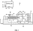
Fig. 1 illustrates an elevation view of an exemplary injection molding machine having two strain gauges and a controller coupled thereto in accordance with various embodiments of the present disclosure; -
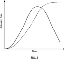
Fig. 2 illustrates an example relationship between a blowing agent and a crosslinking agent over time during injection molding of an expanding crosslinking polymer in accordance with various embodiments of the present disclosure; and -
Fig. 3 illustrates an example relationship between screw position, cavity pressure, and melt pressure during an expanding crosslinking polymer injection molding cycle in accordance with various embodiments of the present disclosure. - Skilled artisans will appreciate that elements in the figures are illustrated for simplicity and clarity and have not necessarily been drawn to scale. For example, the dimensions and/or relative positioning of some of the elements in the figures may be exaggerated relative to other elements to help to improve understanding of various embodiments of the present invention. Also, common but well-understood elements that are useful or necessary in a commercially feasible embodiment are often not depicted in order to facilitate a less obstructed view of these various embodiments. It will further be appreciated that certain actions and/or steps may be described or depicted in a particular order of occurrence while those skilled in the art will understand that such specificity with respect to sequence is not actually required. It will also be understood that the terms and expressions used herein have the ordinary technical meaning as is accorded to such terms and expressions by persons skilled in the technical field as set forth above except where different specific meanings have otherwise been set forth herein.
- An injection molding process for expanding crosslinking polymers is herein described. An example of an expanding crosslinking polymer is EVA, which, when polymerized, includes any number of blowing agents and any number of crosslinking agents which are activated by temperatures. For example, the blowing agents and crosslinking agents may be activated between approximately 160° C and approximately 190° C, or preferably, between approximately 165° C and approximately 185° C, and more preferably, between approximately 170° C and approximately 180° C, which may provide an optimal range for blowing and crosslinking to occur. Other examples are possible.
- As illustrated in
Fig. 1 , aninjection molding machine 100 that molds expanding crosslinking polymers includes aninjection unit 102 and aclamping system 104. The approaches described herein may be suitable for vertical press injection molding machines and any other known types of injection molding machines. Theinjection unit 102 includes ahopper 106 adapted to accept the expanding crosslinking polymer material in the form ofpellets 108 or any other suitable form. In many of these examples, thepellets 108 include any number of foaming agents, crosslinking agents, and the like. Other examples are possible. - The
hopper 106 feeds thepellets 108 into aheated barrel 110 of theinjection unit 102. Upon being fed into theheated barrel 110, thepellets 108 may be driven to the end of theheated barrel 110 by areciprocating screw 112. The heating of theheated barrel 110 and the compression of thepellets 108 by thereciprocating screw 112 causes thepellets 108 to melt, thereby forming a moltenplastic material 114. The moltenplastic material 114 is typically processed at a temperature selected within a range between about 110° C and about 150° C. This melt temperature is below an activation of the moltenplastic material 114. - The
reciprocating screw 112 advances forward and forces the moltenplastic material 114 toward anozzle 116 to form a shot ofplastic material 114 which will ultimately be injected into a mold cavity 122 of amold 118 via one ormore gates 120 which direct the flow of the moltenplastic material 114 to the mold cavity 122. In other embodiments, thenozzle 116 may be separated from one ormore gates 120 by a feed system (not illustrated). The mold cavity 122 is formed between the first and second mold sides 125, 127 of themold 118 and the first and second mold sides 125, 127 are held together under pressure via a press or clampingunit 124. Themold 118 may include any number of mold cavities 122 to increase overall production rates. The shapes and/or designs of the cavities may be identical, similar, and/or different from each other. - The press or clamping
unit 124 applies a predetermined clamping force during the molding process which is greater than the force exerted by the injection pressure acting to separate the twomold halves plastic material 114 is injected into the mold cavity 122. To support these clamping forces, theclamping system 104 may include a mold frame and a mold base, in addition to any other number of components. - The
reciprocating screw 112 continues forward movement, causing the shot of moltenplastic material 114 to be injected into the mold cavity 122. The mold cavity 122 is heated to a temperature that is higher than the activation temperature of the moltenplastic material 114. For example, the mold cavity 122 may be heated to between approximately 160° C and approximately 185° C, and preferably, between approximately 170° C and 180° C. As such, a chemical reaction begins to occur within the moltenplastic material 114 as it contacts sidewalls of the mold cavity 122. It is understood that walls of the mold cavity 122 may be preheated prior to injection the moltenplastic material 114, or alternatively, may be rapidly heated to a suitable temperature as the moltenplastic material 114 enters the mold cavity 122. Examples of heating techniques that may be used to heat surfaces of the mold that define the mold cavity are: Resistive heating (or joule heating), conduction, convection, use of heated fluids (e.g., superheated steam or oil in a manifold or jacket, also heat exchangers), radiative heating (such as through the use of infrared radiation from filaments or other emitters), RF heating (or dielectric heating), electromagnetic inductive heating (also referred to herein as induction heating), use of thermoelectric effect (also called the Peltier-Seebeck effect), vibratory heating, acoustic heating, and use of heat pumps, heat pipes, cartridge heaters, or electrical resistance wires, whether or not their use is considered within the scope of any of the above-listed types of heating. - The
injection molding machine 100 also includes acontroller 140 which is communicatively coupled with themachine 100 viaconnection 145, and is generally used to control operation of theinjection molding machine 100. Theconnection 145 may be any type of wired and/or wireless communications protocol adapted to transmit and/or receive electronic signals. In these examples, thecontroller 140 is in signal communication with at least one sensor, such as, for example, astrain sensor 128 located in thenozzle 116 and/or a strain sensor 129 located on an external surface ofmold 118. The strain sensor 129 may be secured directly to an external surface of themold 118 or may be secured to an external surface of themold 118 by an assembly. An example of a strain sensor located in a nozzle of an injection molding system is disclosed inU.S. Patent Application No. 15/615,996, filed June 7, 2017 - An example of a strain sensor secured directly to an external surface of a mold is disclosed in
U.S. Patent Application No. 15/216,754, filed July 22, 2016 - An example of a strain sensor secured on an external surface of a mold by an assembly is disclosed in
U.S. Patent Application No. 15/448,992, filed March 3, 2017 - In some arrangements, the strain sensor 129 is attached to the
mold 118 by a strain gauge sensor assembly, A. Thefirst mold side 125 of themold 118 has holes drilled therein. A first portion of a strain gauge sensor assembly is secured to thefirst mold side 125 by bolts that are inserted through the first portion of the strain gauge sensor assembly and into thefirst mold side 125 and by a peg which is inserted partially into the first portion of a strain gauge sensor assembly and partially into a hole in thefirst mold side 125. Thesecond mold side 127 has holes drilled into it, and second portion of the strain gauge sensor assembly is secured to thesecond mold side 127 by a bolt that is inserted through the second portion of the strain gauge sensor assembly 262 into thesecond mold side 127 and by a peg 90 which is inserted partially into the second portion of the strain gauge sensor assembly and partially into a hole in thesecond mold side 127. A side of the second portion of the strain gauge sensor assembly is aligned with the parting line of themold 118 along an edge ofsecond mold side 127 and is configured to contact the first portion of the strain gauge sensor assembly when themold 118 is closed. - In some arrangements, the
strain sensor 128 is secured in themachine 100 by a strain gauge nozzle adapter. A region of themachine 100 of the present disclosure is illustrated, with themold 118 at the lower left and a portion of theinjection system 102 at the upper right in the drawing figure. Theheated barrel 110 is provided with a barrel end cap A strain gauge nozzle adapter 342 projects from the barrel end cap. A strain gauge aperture is provided in the strain gauge nozzle adapter. The strain gauge aperture receives thestrain sensor 128 therein, which is secured by friction fit in the embodiment depicted. In other embodiments, thestrain sensor 128 may be secured in place by screwing a screw into the walls of strain gauge aperture above thestrain sensor 128. While a single strain gauge aperture is illustrated, it is understood that the strain gauge nozzle adapter may be provided with a plurality of strain gauge apertures each having a strain sensor 129 secured therein. The strain gauge nozzle adapter is provided between a barrel end cap and a nozzle body having a nozzle provided at an end thereof. While the arrangements illustrated in the drawings show the strain gauge nozzle adapter as a distinct component from the strain gauge nozzle body the strain gauge nozzle adapter is considered part of what is referred to herein as the nozzle assembly, and could be formed integrally with the nozzle body 348.. The nozzle body 348 is in fluid communication with at least one of the mold cavity 122, a gate, a runner, or a manifold of themachine 100. - Returning to
Fig. 1 , it is understood that any number of additional sensors capable of sensing any number of characteristics of themold 118 and/or themachine 100 may be placed at desired locations of themachine 100. In particular, a temperature sensor may be placed on themachine 100, and the data obtained from the temperature sensor may be used in conjunction with measured strain fromstrain sensor 128 or strain sensor 129. Further, although twostrain sensors 128 and 129 are depicted inFig. 1 , a single strain sensor or more than two strain sensors may be provided on themachine 100. - The
controller 140 can be disposed in a number of positions with respect to theinjection molding machine 100. As examples, thecontroller 140 can be integral with themachine 100, contained in an enclosure that is mounted on the machine, contained in a separate enclosure that is positioned adjacent or proximate to the machine, or can be positioned remote from the machine. In some embodiments, thecontroller 140 can partially or fully control functions of the machine via wired and/or wired signal communications as known and/or commonly used in the art. - The
strain sensor 128 generates a signal which is transmitted to an input of thecontroller 140. Thecontroller 140 is in communication with avirtual cavity sensor 141, which is implemented as a program, or a set of software instructions. In this disclosure, the term "virtual cavity sensor" refers to a module that can calculate the value of a non-time dependent variable, such as pressure within mold cavity 122, without directly measuring this non-time dependent variable. If thestrain sensor 128 is not located within thenozzle 116, thecontroller 140 can be set, configured, and/or programmed with logic, commands, and/or executable program instructions to provide appropriate correction factors to estimate or calculate values for the measured characteristic in thenozzle 116. - Likewise, the strain sensor 129 generates a signal which is transmitted to an input of the
controller 140 and thevirtual cavity sensor 141. If the strain sensor 129 is not provided on the mold cavity 122, thecontroller 140 can be set, configured, and/or programmed with logic, commands, and/or executable program instructions to provide appropriate correction factors to estimate or calculate values for the measured characteristic at the end-of-fill position. - It is understood that any number of additional sensors may be used to sense and/or measure operating parameters including but not limited to strain. For example,
U.S. Patent Application No. 15/198,556, filed on June 30, 2016 U.S. Publication No. 2017/0001356 , describes a sensor positioned prior to the end-of-fill to predict the end-of-fill - The
controller 140 is also in signal communication with the screw control 126. In some embodiments, thecontroller 140 generates a signal which is transmitted from an output of thecontroller 140 to the screw control 126. Thecontroller 140 can control any number of characteristics of the machine, such as, for example, injection pressures (by controlling the screw control 126 to advance thescrew 112 at a rate which maintains a desired melt pressure of the moltenplastic material 114 in the nozzle 116), barrel temperatures, clamp closing and/or opening speeds, cooling time, inject forward time, hold profiles, overall cycle time, pressure set points, ejection time, cure profiles, screw recovery speed, and screw velocity. Other examples are possible. - The signal or signals from the
controller 140 may generally be used to control operation of the molding process such that variations in material viscosity, mold cavity 122 temperatures, melt temperatures, and other variations influencing filling rate are taken into account by thecontroller 140. Adjustments may be made by thecontroller 140 in real time or in near-real time (that is, with a minimal delay betweensensors 128, 129 sensing values and changes being made to the process), or corrections can be made in subsequent cycles. Furthermore, several signals derived from any number of individual cycles may be used as a basis for making adjustments to the molding process. Thecontroller 140 may be connected to thesensors 128, 129, the screw control 126, and or any other components in themachine 100 via any type of signal communication known in the art or hereafter developed. - The
controller 140 includesvirtual cavity sensor 141 adapted to control its operation, any number of hardware elements 142 (such as, for example, a memory module and/or processors), any number ofinputs 143, any number ofoutputs 144, and any number ofconnections 145. Thevirtual cavity sensor 141 may be loaded directly onto a memory module of thecontroller 140 in the form of a non-transitory computer readable medium, or may alternatively be located remotely from thecontroller 140 and be in communication with thecontroller 140 via any number of controlling approaches. Thevirtual cavity sensor 141 includes logic, commands, and/or executable program instructions which may contain logic and/or commands for controlling theinjection molding machine 100 according to a mold cycle. Thevirtual cavity sensor 141 may or may not include an operating system, an operating environment, an application environment, and/or a user interface. - The
hardware 142 uses theinputs 143 to receive signals, data, and information from the injection molding machine being controlled by thecontroller 140. Thehardware 142 uses theoutputs 144 to send signals, data, and/or other information to the injection molding machine. Theconnection 145 represents a pathway through which signals, data, and information can be transmitted between thecontroller 140 and itsinjection molding machine 100. In various embodiments this pathway may be a physical connection or a non-physical communication link that works analogous to a physical connection, direct or indirect, configured in any way described herein or known in the art. In various embodiments, thecontroller 140 can be configured in any additional or alternate way known in the art. - The
connection 145 represents a pathway through which signals, data, and information can be transmitted between thecontroller 140 and theinjection molding machine 100. In various embodiments, these pathways may be physical connections or non-physical communication links that work analogously to either direct or indirect physical connections configured in any way described herein or known in the art. In various embodiments, thecontroller 140 can be configured in any additional or alternate way known in the art. - As previously stated, during an injection molding cycle, the
strain sensors 128, 129 are adapted to measure strain related to operation of themachine 100. Thevirtual cavity sensor 141 is configured to calculate from the measured strain at least one non-time dependent variable during the injection mold cycle. Although the arrangement depicted shows twostrain sensors 128 and 129 for measuring strain, thevirtual cavity sensor 141 can calculate at least one non-time dependent variable based on data from a single strain sensor or from two or more strain sensors. Thevirtual cavity sensor 141 may calculate the at least one non-time dependent variable using non-strain data as well, such as temperature data provided by a temperature sensor. During operation, thecontroller 140 commences a hold profile which may be stored in thevirtual cavity sensor 141. In some examples, the hold profile may be commenced upon the calculated variable reaching a threshold value. Upon completing the hold profile, thecontroller 140 will send a signal to the machine that causes the mold cavity 122 to open and to eject the part from themold 118 so that it can commence the cure profile, where necessary continued expansion and crosslinking occurs to form a structurally sound molded part. For example, a structurally sound molded part may be free of divots, dwells, flash, partial fills, burns, tears, minimal imperfections such as sink marks and/or swirls on the surface layer, weakness at thickness changes, and should have uniformity of mechanical properties. - In these examples, the variable or characteristic may be one other than time (e.g., a cycle, step, or any other time), thus time is not directly measured and used to determine the length of the hold profile, and accordingly, when to eject the part. Rather, the variable or characteristic relies on another value or indicator as a determining factor for part readiness. The use of one or more non-time dependent variables is advantageous because during successive runs, even with the same supply of
pellets 108, variations in pellet quality, catalyst stability, ambient conditions, or other factors may influence the cross-linking of the polymer material from shot-to-shot. While a time-dependent process may provide satisfactory parts most of the time, a system that determines ejection readiness based on one or more non-time dependent variables is preferable, as this provides a more accurate assessment for each individual shot or run of the molding system. - Turning to
Fig. 2 , which illustrates an example relationship between the blowing agent and the crosslinking agent of the expanding crosslinking polymer over time, during the injection molding process, the blowing agent first activates at a given temperature and begins to react over time. Generally speaking, the blowing agent, depicted by the solid line inFig. 2 , will cause the part to expand, thus dictating the part size. At approximately the same point that the blowing agent is activated, the crosslinking agent, depicted by the dashed line inFig. 2 , activates and begins to form structural bonds within the polymer. Both the blowing agent and crosslinking agent generate exothermic reactions, thus they generate heat as the reaction advances, which in turn causes the blowing and crosslinking agents to continue their respective chemical reactions. When the blowing process concludes, the reaction will stop emitting heat. At this point, crosslinking continues until the part is sufficiently formed, meaning the moltenplastic material 114 is no longer in a flowable state. - Referring again to
Fig. 1 , upon the moltenplastic material 114 substantially filling the mold cavity 122, a hold profile is commenced. During the hold profile, which may commence upon the calculated variable (which can be calculated by thevirtual cavity sensor 141 from strain measured by any ofstrain sensors 128 and/or 129) reaching a first threshold value, additional moltenplastic material 114 is restricted from being injected into the mold cavity 122. This may occur by shutting off the supply of moltenplastic material 114, or alternatively, by controlling movement of thescrew 112. Additionally, the mold cavity 122 is held closed during the hold profile. Upon the calculated variable (which can be calculated by thevirtual cavity sensor 141 from strain measured by any ofsensors 128 and/or 129) reaching a second threshold value,controller 140 causes the hold profile to end, whereby the mold cavity 122 is opened and the part is ejected from themold 118 and the cure profile to commence. - Turning now to
Fig. 3 , which represents an example expanding crosslinking polymerinjection molding cycle 300, the measured variable may reach first and second threshold values.Line 302 depicts the position of thescrew 112 under a certain injection pressure (i.e., 5,000 psi) once the cavity pressure is built to a desired and/or designated trigger point. As an example, the pressure can decrease from approximately 5,000 psi to approximately 2,000 psi at this point. In this example, during injection of the expanding crosslinking polymer, melt pressure, which is depicted byline 304, is first increased and then held to a substantially constant value. Accordingly, the calculated variable (which can be calculated by thevirtual cavity sensor 141 from strain measured by any ofstrain sensors 128 and/or 129) may be a melt pressure. As a non-limiting example, the melt pressure may be between approximately 0 psi and approximately 11,000 psi. Other examples of suitable melt pressures are possible. Further, it is understood that in some examples, the melt pressure may not be held to a substantially constant value. - In
Fig. 3 ,line 306 depicts the calculated variable as a cavity pressure value. In the illustrated example, in region I, the calculated cavity pressure value (which can be calculated by thevirtual cavity sensor 141 from strain measured by any ofstrain sensors 128 and/or 129) exceeds the first threshold value. As previously noted, in some examples, during the injection molding process, the mold cavity 122 can be essentially completely filled with moltenplastic material 114. - In this example, the calculated cavity pressure value is defined as a cavity pressure greater than a nominal value, which may be at least partially caused by the molten
plastic material 114 completely filling the mold cavity 122 and exerting a pressure on the cavity walls. The increase in cavity pressure may additionally or alternatively be caused by the expansion of the moltenplastic material 114 within the mold cavity 122. It is understood that in some examples, the first threshold value may be any desired quantity. For example, the first threshold value may be a distinct cavity pressure value, such as, approximately 100 psi. Other examples are possible. - Upon the
virtual cavity sensor 141 calculating a calculated cavity pressure value exceeding the first threshold value, thecontroller 140 commences the hold profile. As illustrated byline 304 inFig. 3 , the melt pressure is then adjusted (for example, reduced). In the illustrated example, the melt pressure is again held to a substantially constant value, such as, for example, between approximately 500 psi and approximately 3,500 psi. Other examples are possible. This pressure is maintained by controlling movement of thescrew 112 to a hold pressure measured at the nozzle by thesensor 128. - At region II, as the melt pressure is maintained, the calculated cavity pressure increases as the molten
plastic material 114 begins to blow or expand. Upon thevirtual cavity sensor 141 calculating a cavity pressure value that exceeds the second threshold value, the hold profile is completed, and thecontroller 140 causes the part to be ejected from the mold cavity 122. As an example, the second threshold value may be a distinct cavity pressure value, such as, between approximately 100 psi and approximately 2,000 psi. Other examples are possible. This second threshold value is indicative of the expanding crosslinking polymeric part being sufficiently structurally sound to complete its expansion and crosslinking outside of the mold cavity. At this point, the mold cavity 122 is opened, thus the melt pressure drops to approximately 0. - In some examples, the calculated variable calculated by the
virtual cavity sensor 141 from measured strain is a cavity temperature value. Accordingly, in these examples, the first threshold value may be a cavity temperature value that is representative of the mold cavity 122 being substantially completely filled. For example, the first threshold temperature value may be between approximately 168° C and approximately 176° C. Other examples are possible. Similarly, in these examples, the second threshold value may be a cavity temperature value that is representative of the moltenplastic material 114 being sufficiently structurally sound for ejection. In these examples, the cavity temperature may plateau or decrease at a point when the part is ready to be ejected from the mold cavity 122. As a non-limiting example, the second threshold temperature value may be between approximately 160° C and approximately 180° C. Other examples are possible. - Because the mold cavity 122 is substantially completely filled (e.g., between approximately 95% and approximately 99% fill) prior to commencement of the hold profile, and because pressure is applied to the molten
plastic material 114 thereby holding it against the heated walls of the mold cavity 122, heat is uniformly distributed or transferred to the moltenplastic material 114 due to the increased surface contact. Advantageously, the blowing and crosslinking agents will activate more uniformly, thus forming more cohesive bonds. - So configured, the hold profile can be described as the combination of regions I and II in
Fig. 3 . Theinjection molding machine 100 does not contemplate the actual duration of time required to commence the hold profile, and rather, themachine 100 operates in a closed loop mold holding pattern. So configured, molded parts have more consistent part sizes and appearances, as well as a uniform skin layer due to consistent heat transfer. Further, not only will particular parts have consistent dimensions, the hold profile helps to ensure reliability and consistency across a range of sizes of parts, which has been particularly challenging with respect to expanding crosslinking polymer articles. Further still, the hold profile provides better control over the process, allowing the part to dictate when the cavity is full and ready to be ejected. In some examples, using the hold profile can decrease the overall cycle time due to a reduced cure time. Additionally, the use of the hold profile can generate parts having more uniformity in cell structure due to free radical molecules becoming aligned. As such, the hold profile makes a more consistent and stable dimensioned part, with consistent physical properties. - At region III, the
controller 140 commences a cure profile. As illustrated inFig. 3 , the cavity pressure will ultimately plateau as the part ceases to further expand. Upon thevirtual cavity sensor 141 calculating a calculated cavity pressure value that exceeds a third threshold value, the cure profile is completed, and the part is ejected, removed from the cavity 122 or theentire machine 100, and transferred to a stabilization tunnel where curing occurs. - According to the invention, the third threshold value is a predetermined rate of change in pressure values, which may indicate that the pressure is no longer increasing. This third threshold value is indicative of the expanding crosslinking polymeric part being essentially fully formed and ready for further processing. By using the third threshold value to determine the duration of the cure profile, the
machine 100 will not prematurely eject parts that have not fully cured. Additionally, themachine 100 reduces inefficiencies by using unnecessarily long cure times, which can consume unnecessary power and reduce overall yields of the machine. - Those skilled in the art will recognize that a wide variety of modifications, alterations, and combinations can be made with respect to the above described embodiments without departing from the scope of the invention defined by the appended claims.
Claims (10)
- A method for injection molding an expanding crosslinking polymer part in an injection molding system, the method comprising:injecting molten expanding crosslinking polymer into a mold cavity;measuring strain at the mold cavity or at another location within the injection molding system during the injection molding cycle;calculating from the measured strain at least one non-time dependent variable during the injection mold cycle, wherein the non-time dependent variable is a variable that is independent from a fixed or specified hold time;commencing a hold profile for the expanding crosslinking polymer part;upon completing the hold profile,commencing a cure profile for the molded part, and ejecting the part from the mold cavity;whereincommencing the hold profile comprises:upon the calculated at least one non-time dependent variables reaching a first threshold value, commencing the hold profile;restricting additional molten expanding crosslinking polymer from being injected into the mold cavity; andupon the calculated at least one non-time dependent variables reaching a second threshold value, terminating the hold profilewherein the first threshold value is indicative of the mold cavity being substantially full of molten expanding cross linking polymer;wherein the second threshold value is indicative of the part being structurally sound;commencing the cure profile comprises:
upon the at least one calculated non-time dependent variable reaching a third threshold value, terminating the cure profile, wherein the third threshold value is a predetermined rate of change in a cavity pressure value. - The method of claim 1, wherein the calculated at least one non-time dependent variable comprises a cavity pressure value.
- The method of any one of claims 1-2, wherein the hold profile commences at a substantially constant pressure.
- The method of any one of claims 1-3, wherein the third threshold value is indicative of the part being structurally sound.
- The method of any one of claims 1-4, wherein commencing the cure profile comprises allowing the part to cool for a predetermined amount of time.
- An expanding crosslinking polymer injection molding system comprising:an injection molding machine comprising an injection unit and a mold forming a mold cavity, the injection unit adapted to receive and inject a molten expanding crosslinking plastic material into the mold cavity to form a molded part;a controller adapted to control operation of the injection molding machine; andone or more sensors coupled to the injection molding machine and the controller;wherein at least one of the one or more sensors is adapted to measure strain during the injection mold cycle and to calculate from the measured strain at least one non-time dependent variable during the injection mold cycle, wherein the non-time dependent variable is a variable that is independent from a fixed or specified hold time, wherein the controller is adapted to commence a hold profile for the expanding crosslinking polymer part and is further adapted to commence a cure profile for the molded part and cause the molded part to be ejected from the mold cavity upon completing the hold profilewhereinthe controller is adapted to commence the hold profile by commencing the hold profile when at least one non-time dependent variable calculated from the measured strain reaches a first threshold value, to restrict additional molten expanding crosslinking polymer from being injected into the mold cavity, and to terminate the hold profile when the calculated at least one non-time dependent variables reaches a second threshold value, wherein the first threshold value is indicative of the mold cavity being substantially full of molten expanding cross linking polymer, and wherein the second threshold value is indicative of the part being structurally sound; andcommencing the cure profile comprises:upon the calculated at least one non-time dependent variable reaching a third threshold value, terminating the hold profile.wherein the third threshold value is a predetermined rate of change in a cavity pressure value.
- The system of claim 6, wherein the calculated at least one non-time dependent variable comprises a cavity pressure value.
- The system of any one of claims 6-7 , wherein the third threshold value is indicative of the part being structurally sound.
- The system of any one of claims 6-8, wherein commencing the cure profile comprises allowing the part to cool for a predetermined amount of time.
- The system of any one of claims 6-9, wherein the hold profile commences at a substantially constant pressure.
Applications Claiming Priority (2)
| Application Number | Priority Date | Filing Date | Title |
|---|---|---|---|
| US201762523067P | 2017-06-21 | 2017-06-21 | |
| PCT/US2018/035079 WO2018236561A1 (en) | 2017-06-21 | 2018-05-30 | INJECTION MOLDING OF CROSSLINKING POLYMERS USING STRAIN DATA |
Publications (2)
| Publication Number | Publication Date |
|---|---|
| EP3642001A1 EP3642001A1 (en) | 2020-04-29 |
| EP3642001B1 true EP3642001B1 (en) | 2022-12-14 |
Family
ID=62683460
Family Applications (1)
| Application Number | Title | Priority Date | Filing Date |
|---|---|---|---|
| EP18732567.5A Active EP3642001B1 (en) | 2017-06-21 | 2018-05-30 | Injection molding of crosslinking polymers using strain data |
Country Status (7)
| Country | Link |
|---|---|
| US (2) | US11040472B2 (en) |
| EP (1) | EP3642001B1 (en) |
| CN (1) | CN110730710B (en) |
| CA (1) | CA3064581A1 (en) |
| MX (1) | MX2019014014A (en) |
| TW (1) | TWI754071B (en) |
| WO (1) | WO2018236561A1 (en) |
Families Citing this family (8)
| Publication number | Priority date | Publication date | Assignee | Title |
|---|---|---|---|---|
| CN110494266B (en) * | 2017-04-04 | 2022-05-17 | 艾姆弗勒克斯有限公司 | In-mold time-independent determination of ejection readiness of injection molded parts |
| MX2019014014A (en) * | 2017-06-21 | 2020-08-17 | Imflux Inc | Injection molding of crosslinking polymers using strain data. |
| TWI660834B (en) * | 2018-06-22 | 2019-06-01 | 瑞皇精密工業股份有限公司 | Injection molding device and injection method thereof |
| EP3883739B1 (en) | 2018-11-21 | 2025-09-10 | NIKE Innovate C.V. | System for a foaming process |
| CN113165232A (en) * | 2018-11-21 | 2021-07-23 | 耐克创新有限合伙公司 | Systems and methods for forming sole structures |
| CN110561685B (en) * | 2019-10-16 | 2024-10-15 | 江苏铁锚玻璃股份有限公司 | Edge wrapping device and edge wrapping method for glass |
| CN114131020B (en) * | 2021-11-24 | 2022-08-19 | 湖南大学 | High-interface-strength complicated cavity foamed aluminum filling device and method |
| JP2025030637A (en) * | 2023-08-24 | 2025-03-07 | セイコーエプソン株式会社 | Injection Molding Equipment |
Family Cites Families (32)
| Publication number | Priority date | Publication date | Assignee | Title |
|---|---|---|---|---|
| US4208176A (en) * | 1975-06-16 | 1980-06-17 | Litton Industrial Products, Inc. | Time independent cycle control for plastic injection molding machines |
| JPS53135357A (en) | 1977-04-28 | 1978-11-25 | Itsuo Shibata | Inspecting apparatus |
| JPS56146741A (en) * | 1980-04-18 | 1981-11-14 | Hitachi Ltd | Setting of holding time and system therefor |
| DE3780322D1 (en) * | 1986-02-14 | 1992-08-20 | Demag Kunststofftech | METHOD AND DEVICE FOR REGULATING THE INJECTION MOLDING PROCESS. |
| US4767579A (en) | 1987-11-02 | 1988-08-30 | Eastman Kodak Company | Method of precision volumetric control of a moldable material in an injection molding process |
| DE3738248A1 (en) | 1987-11-11 | 1988-04-28 | Ver Foerderung Inst Kunststoff | METHOD FOR REPRODUCIBLE TOOL FILLING WITH REACTIVE MOLDS |
| DE4140392C2 (en) | 1991-12-07 | 1997-02-20 | Bosch Gmbh Robert | Process for controlling an injection molding process |
| US5384079A (en) | 1993-01-06 | 1995-01-24 | The United States Of America As Represented By The Secretary Of Commerce | Method for detecting thermodynamic phase transitions during polymer injection molding |
| US5566743A (en) | 1994-05-02 | 1996-10-22 | Guergov; Milko G. | Method of injecting molten metal into a mold cavity |
| US5519211A (en) | 1994-06-14 | 1996-05-21 | United States Of America As Represented By The Secretary Of Commerce | Method and apparatus for monitoring resin crystallization and shrinkage during polymer molding |
| US5447425A (en) * | 1994-08-11 | 1995-09-05 | Leopardex Industrial Co., Ltd. | Injection molding assembly for forming foam products |
| JP3928318B2 (en) | 1999-12-29 | 2007-06-13 | 株式会社カネカ | In-mold foam molding method of polyolefin synthetic resin |
| EP1689573A4 (en) | 2003-11-20 | 2011-02-09 | William A Nicol | Sensory system and method thereof |
| US7072735B2 (en) | 2004-04-23 | 2006-07-04 | Husky Injection Molding Systems Ltd. | Control system for utilizing active material elements in a molding system |
| WO2006007749A1 (en) | 2004-07-21 | 2006-01-26 | Kistler Holding Ag | Temperature-dependent demolding |
| US8753553B2 (en) * | 2008-04-14 | 2014-06-17 | University Of Massachusetts | Methods for forming injected molded parts and in-mold sensors therefor |
| JP5092927B2 (en) * | 2008-06-20 | 2012-12-05 | ソニー株式会社 | INJECTION MOLDING CONTROL METHOD AND INJECTION MOLDING CONTROL DEVICE |
| US8425216B2 (en) * | 2011-03-11 | 2013-04-23 | Mold-Masters (2007) Limited | Cycle counting system for injection molding assembly |
| US8641943B1 (en) | 2012-05-24 | 2014-02-04 | Kipe Molds, Inc. | Apparatus and method for filling a mold with a liquid material |
| US9604398B2 (en) | 2012-11-08 | 2017-03-28 | Imflux Inc | Injection mold with fail safe pressure mechanism |
| CN105431273B (en) | 2013-08-01 | 2018-06-19 | 艾姆弗勒克斯有限公司 | The injection molding machine and method of the variation of material property during consideration injection operation |
| EP3750955B1 (en) * | 2013-12-12 | 2023-01-18 | Diab International AB | Expanded pvc foam |
| JP6169633B2 (en) * | 2015-03-04 | 2017-07-26 | ファナック株式会社 | Pressure control device for injection molding machine |
| WO2016153301A1 (en) * | 2015-03-24 | 2016-09-29 | 박영설 | Midsole forming device and midsole manufactured thereby |
| EP3317075A1 (en) | 2015-06-30 | 2018-05-09 | Imflux Inc. | Method of injection molding with constant-velocity flow front control |
| US10226889B2 (en) * | 2015-07-22 | 2019-03-12 | Imflux, Inc. | Method of injection molding using one or more external sensors as a virtual cavity sensor |
| JP6647144B2 (en) | 2015-12-11 | 2020-02-14 | 株式会社青木固研究所 | Injection mold and preform molding method and preform of injection stretch blow molding machine, and container molding method and container |
| CN110494266B (en) | 2017-04-04 | 2022-05-17 | 艾姆弗勒克斯有限公司 | In-mold time-independent determination of ejection readiness of injection molded parts |
| WO2018223139A1 (en) * | 2017-06-02 | 2018-12-06 | Zephyros, Inc. | Anti-flutter baffle |
| CA3065817A1 (en) | 2017-06-15 | 2018-12-20 | iMFLUX Inc. | Injection molding of crosslinking polymers |
| EP3638483A1 (en) | 2017-06-15 | 2020-04-22 | Imflux Inc. | Injection molding of crosslinking polymers |
| MX2019014014A (en) * | 2017-06-21 | 2020-08-17 | Imflux Inc | Injection molding of crosslinking polymers using strain data. |
-
2018
- 2018-05-30 MX MX2019014014A patent/MX2019014014A/en unknown
- 2018-05-30 CA CA3064581A patent/CA3064581A1/en active Pending
- 2018-05-30 WO PCT/US2018/035079 patent/WO2018236561A1/en not_active Ceased
- 2018-05-30 EP EP18732567.5A patent/EP3642001B1/en active Active
- 2018-05-30 US US15/992,855 patent/US11040472B2/en active Active
- 2018-05-30 CN CN201880038559.XA patent/CN110730710B/en active Active
- 2018-06-11 TW TW107119945A patent/TWI754071B/en not_active IP Right Cessation
-
2021
- 2021-05-17 US US17/321,908 patent/US11642821B2/en active Active
Also Published As
| Publication number | Publication date |
|---|---|
| CN110730710B (en) | 2022-05-17 |
| US20210268705A1 (en) | 2021-09-02 |
| TW201904743A (en) | 2019-02-01 |
| US11642821B2 (en) | 2023-05-09 |
| MX2019014014A (en) | 2020-08-17 |
| TWI754071B (en) | 2022-02-01 |
| CA3064581A1 (en) | 2018-12-27 |
| US11040472B2 (en) | 2021-06-22 |
| US20180370108A1 (en) | 2018-12-27 |
| CN110730710A (en) | 2020-01-24 |
| EP3642001A1 (en) | 2020-04-29 |
| WO2018236561A1 (en) | 2018-12-27 |
Similar Documents
| Publication | Publication Date | Title |
|---|---|---|
| EP3642001B1 (en) | Injection molding of crosslinking polymers using strain data | |
| US20220024098A1 (en) | Injection molding of crosslinking polymers | |
| EP3846997B1 (en) | Systems and approaches for controlling an injection molding machine | |
| EP3846996B1 (en) | Closed loop control for injection molding processes | |
| CN112218751A (en) | Method for simultaneous closed-loop control of gas assist and gas back-pressure during injection molding in relation to plastic melt pressure and plastic melt flow position | |
| US20210170655A1 (en) | Injection molding of crosslinking polymers | |
| US20210387391A1 (en) | Independent startup mode for injection molding | |
| CN115697662A (en) | Injection molding with variable volume recovery |
Legal Events
| Date | Code | Title | Description |
|---|---|---|---|
| STAA | Information on the status of an ep patent application or granted ep patent |
Free format text: STATUS: UNKNOWN |
|
| STAA | Information on the status of an ep patent application or granted ep patent |
Free format text: STATUS: THE INTERNATIONAL PUBLICATION HAS BEEN MADE |
|
| PUAI | Public reference made under article 153(3) epc to a published international application that has entered the european phase |
Free format text: ORIGINAL CODE: 0009012 |
|
| STAA | Information on the status of an ep patent application or granted ep patent |
Free format text: STATUS: REQUEST FOR EXAMINATION WAS MADE |
|
| 17P | Request for examination filed |
Effective date: 20200108 |
|
| AK | Designated contracting states |
Kind code of ref document: A1 Designated state(s): AL AT BE BG CH CY CZ DE DK EE ES FI FR GB GR HR HU IE IS IT LI LT LU LV MC MK MT NL NO PL PT RO RS SE SI SK SM TR |
|
| AX | Request for extension of the european patent |
Extension state: BA ME |
|
| DAV | Request for validation of the european patent (deleted) | ||
| DAX | Request for extension of the european patent (deleted) | ||
| STAA | Information on the status of an ep patent application or granted ep patent |
Free format text: STATUS: EXAMINATION IS IN PROGRESS |
|
| 17Q | First examination report despatched |
Effective date: 20210702 |
|
| GRAP | Despatch of communication of intention to grant a patent |
Free format text: ORIGINAL CODE: EPIDOSNIGR1 |
|
| STAA | Information on the status of an ep patent application or granted ep patent |
Free format text: STATUS: GRANT OF PATENT IS INTENDED |
|
| INTG | Intention to grant announced |
Effective date: 20220323 |
|
| GRAJ | Information related to disapproval of communication of intention to grant by the applicant or resumption of examination proceedings by the epo deleted |
Free format text: ORIGINAL CODE: EPIDOSDIGR1 |
|
| STAA | Information on the status of an ep patent application or granted ep patent |
Free format text: STATUS: EXAMINATION IS IN PROGRESS |
|
| INTC | Intention to grant announced (deleted) | ||
| GRAS | Grant fee paid |
Free format text: ORIGINAL CODE: EPIDOSNIGR3 |
|
| STAA | Information on the status of an ep patent application or granted ep patent |
Free format text: STATUS: GRANT OF PATENT IS INTENDED |
|
| GRAP | Despatch of communication of intention to grant a patent |
Free format text: ORIGINAL CODE: EPIDOSNIGR1 |
|
| INTG | Intention to grant announced |
Effective date: 20221006 |
|
| GRAA | (expected) grant |
Free format text: ORIGINAL CODE: 0009210 |
|
| STAA | Information on the status of an ep patent application or granted ep patent |
Free format text: STATUS: THE PATENT HAS BEEN GRANTED |
|
| AK | Designated contracting states |
Kind code of ref document: B1 Designated state(s): AL AT BE BG CH CY CZ DE DK EE ES FI FR GB GR HR HU IE IS IT LI LT LU LV MC MK MT NL NO PL PT RO RS SE SI SK SM TR |
|
| REG | Reference to a national code |
Ref country code: GB Ref legal event code: FG4D |
|
| REG | Reference to a national code |
Ref country code: CH Ref legal event code: EP |
|
| REG | Reference to a national code |
Ref country code: DE Ref legal event code: R096 Ref document number: 602018044240 Country of ref document: DE |
|
| REG | Reference to a national code |
Ref country code: IE Ref legal event code: FG4D |
|
| REG | Reference to a national code |
Ref country code: AT Ref legal event code: REF Ref document number: 1537421 Country of ref document: AT Kind code of ref document: T Effective date: 20230115 |
|
| REG | Reference to a national code |
Ref country code: LT Ref legal event code: MG9D |
|
| REG | Reference to a national code |
Ref country code: NL Ref legal event code: MP Effective date: 20221214 |
|
| PG25 | Lapsed in a contracting state [announced via postgrant information from national office to epo] |
Ref country code: SE Free format text: LAPSE BECAUSE OF FAILURE TO SUBMIT A TRANSLATION OF THE DESCRIPTION OR TO PAY THE FEE WITHIN THE PRESCRIBED TIME-LIMIT Effective date: 20221214 Ref country code: NO Free format text: LAPSE BECAUSE OF FAILURE TO SUBMIT A TRANSLATION OF THE DESCRIPTION OR TO PAY THE FEE WITHIN THE PRESCRIBED TIME-LIMIT Effective date: 20230314 Ref country code: LT Free format text: LAPSE BECAUSE OF FAILURE TO SUBMIT A TRANSLATION OF THE DESCRIPTION OR TO PAY THE FEE WITHIN THE PRESCRIBED TIME-LIMIT Effective date: 20221214 Ref country code: FI Free format text: LAPSE BECAUSE OF FAILURE TO SUBMIT A TRANSLATION OF THE DESCRIPTION OR TO PAY THE FEE WITHIN THE PRESCRIBED TIME-LIMIT Effective date: 20221214 |
|
| REG | Reference to a national code |
Ref country code: AT Ref legal event code: MK05 Ref document number: 1537421 Country of ref document: AT Kind code of ref document: T Effective date: 20221214 |
|
| PG25 | Lapsed in a contracting state [announced via postgrant information from national office to epo] |
Ref country code: RS Free format text: LAPSE BECAUSE OF FAILURE TO SUBMIT A TRANSLATION OF THE DESCRIPTION OR TO PAY THE FEE WITHIN THE PRESCRIBED TIME-LIMIT Effective date: 20221214 Ref country code: LV Free format text: LAPSE BECAUSE OF FAILURE TO SUBMIT A TRANSLATION OF THE DESCRIPTION OR TO PAY THE FEE WITHIN THE PRESCRIBED TIME-LIMIT Effective date: 20221214 Ref country code: HR Free format text: LAPSE BECAUSE OF FAILURE TO SUBMIT A TRANSLATION OF THE DESCRIPTION OR TO PAY THE FEE WITHIN THE PRESCRIBED TIME-LIMIT Effective date: 20221214 Ref country code: GR Free format text: LAPSE BECAUSE OF FAILURE TO SUBMIT A TRANSLATION OF THE DESCRIPTION OR TO PAY THE FEE WITHIN THE PRESCRIBED TIME-LIMIT Effective date: 20230315 |
|
| PG25 | Lapsed in a contracting state [announced via postgrant information from national office to epo] |
Ref country code: NL Free format text: LAPSE BECAUSE OF FAILURE TO SUBMIT A TRANSLATION OF THE DESCRIPTION OR TO PAY THE FEE WITHIN THE PRESCRIBED TIME-LIMIT Effective date: 20221214 |
|
| PG25 | Lapsed in a contracting state [announced via postgrant information from national office to epo] |
Ref country code: SM Free format text: LAPSE BECAUSE OF FAILURE TO SUBMIT A TRANSLATION OF THE DESCRIPTION OR TO PAY THE FEE WITHIN THE PRESCRIBED TIME-LIMIT Effective date: 20221214 Ref country code: RO Free format text: LAPSE BECAUSE OF FAILURE TO SUBMIT A TRANSLATION OF THE DESCRIPTION OR TO PAY THE FEE WITHIN THE PRESCRIBED TIME-LIMIT Effective date: 20221214 Ref country code: PT Free format text: LAPSE BECAUSE OF FAILURE TO SUBMIT A TRANSLATION OF THE DESCRIPTION OR TO PAY THE FEE WITHIN THE PRESCRIBED TIME-LIMIT Effective date: 20230414 Ref country code: ES Free format text: LAPSE BECAUSE OF FAILURE TO SUBMIT A TRANSLATION OF THE DESCRIPTION OR TO PAY THE FEE WITHIN THE PRESCRIBED TIME-LIMIT Effective date: 20221214 Ref country code: EE Free format text: LAPSE BECAUSE OF FAILURE TO SUBMIT A TRANSLATION OF THE DESCRIPTION OR TO PAY THE FEE WITHIN THE PRESCRIBED TIME-LIMIT Effective date: 20221214 Ref country code: CZ Free format text: LAPSE BECAUSE OF FAILURE TO SUBMIT A TRANSLATION OF THE DESCRIPTION OR TO PAY THE FEE WITHIN THE PRESCRIBED TIME-LIMIT Effective date: 20221214 Ref country code: AT Free format text: LAPSE BECAUSE OF FAILURE TO SUBMIT A TRANSLATION OF THE DESCRIPTION OR TO PAY THE FEE WITHIN THE PRESCRIBED TIME-LIMIT Effective date: 20221214 |
|
| PG25 | Lapsed in a contracting state [announced via postgrant information from national office to epo] |
Ref country code: SK Free format text: LAPSE BECAUSE OF FAILURE TO SUBMIT A TRANSLATION OF THE DESCRIPTION OR TO PAY THE FEE WITHIN THE PRESCRIBED TIME-LIMIT Effective date: 20221214 Ref country code: PL Free format text: LAPSE BECAUSE OF FAILURE TO SUBMIT A TRANSLATION OF THE DESCRIPTION OR TO PAY THE FEE WITHIN THE PRESCRIBED TIME-LIMIT Effective date: 20221214 Ref country code: IS Free format text: LAPSE BECAUSE OF FAILURE TO SUBMIT A TRANSLATION OF THE DESCRIPTION OR TO PAY THE FEE WITHIN THE PRESCRIBED TIME-LIMIT Effective date: 20230414 Ref country code: AL Free format text: LAPSE BECAUSE OF FAILURE TO SUBMIT A TRANSLATION OF THE DESCRIPTION OR TO PAY THE FEE WITHIN THE PRESCRIBED TIME-LIMIT Effective date: 20221214 |
|
| REG | Reference to a national code |
Ref country code: DE Ref legal event code: R097 Ref document number: 602018044240 Country of ref document: DE |
|
| PLBE | No opposition filed within time limit |
Free format text: ORIGINAL CODE: 0009261 |
|
| STAA | Information on the status of an ep patent application or granted ep patent |
Free format text: STATUS: NO OPPOSITION FILED WITHIN TIME LIMIT |
|
| PG25 | Lapsed in a contracting state [announced via postgrant information from national office to epo] |
Ref country code: DK Free format text: LAPSE BECAUSE OF FAILURE TO SUBMIT A TRANSLATION OF THE DESCRIPTION OR TO PAY THE FEE WITHIN THE PRESCRIBED TIME-LIMIT Effective date: 20221214 |
|
| 26N | No opposition filed |
Effective date: 20230915 |
|
| PG25 | Lapsed in a contracting state [announced via postgrant information from national office to epo] |
Ref country code: SI Free format text: LAPSE BECAUSE OF FAILURE TO SUBMIT A TRANSLATION OF THE DESCRIPTION OR TO PAY THE FEE WITHIN THE PRESCRIBED TIME-LIMIT Effective date: 20221214 |
|
| REG | Reference to a national code |
Ref country code: CH Ref legal event code: PL |
|
| PG25 | Lapsed in a contracting state [announced via postgrant information from national office to epo] |
Ref country code: MC Free format text: LAPSE BECAUSE OF FAILURE TO SUBMIT A TRANSLATION OF THE DESCRIPTION OR TO PAY THE FEE WITHIN THE PRESCRIBED TIME-LIMIT Effective date: 20221214 |
|
| REG | Reference to a national code |
Ref country code: BE Ref legal event code: MM Effective date: 20230531 |
|
| PG25 | Lapsed in a contracting state [announced via postgrant information from national office to epo] |
Ref country code: MC Free format text: LAPSE BECAUSE OF FAILURE TO SUBMIT A TRANSLATION OF THE DESCRIPTION OR TO PAY THE FEE WITHIN THE PRESCRIBED TIME-LIMIT Effective date: 20221214 Ref country code: LU Free format text: LAPSE BECAUSE OF NON-PAYMENT OF DUE FEES Effective date: 20230530 Ref country code: LI Free format text: LAPSE BECAUSE OF NON-PAYMENT OF DUE FEES Effective date: 20230531 Ref country code: CH Free format text: LAPSE BECAUSE OF NON-PAYMENT OF DUE FEES Effective date: 20230531 |
|
| REG | Reference to a national code |
Ref country code: IE Ref legal event code: MM4A |
|
| PG25 | Lapsed in a contracting state [announced via postgrant information from national office to epo] |
Ref country code: IE Free format text: LAPSE BECAUSE OF NON-PAYMENT OF DUE FEES Effective date: 20230530 |
|
| PG25 | Lapsed in a contracting state [announced via postgrant information from national office to epo] |
Ref country code: IE Free format text: LAPSE BECAUSE OF NON-PAYMENT OF DUE FEES Effective date: 20230530 |
|
| PG25 | Lapsed in a contracting state [announced via postgrant information from national office to epo] |
Ref country code: IT Free format text: LAPSE BECAUSE OF FAILURE TO SUBMIT A TRANSLATION OF THE DESCRIPTION OR TO PAY THE FEE WITHIN THE PRESCRIBED TIME-LIMIT Effective date: 20221214 Ref country code: BE Free format text: LAPSE BECAUSE OF NON-PAYMENT OF DUE FEES Effective date: 20230531 |
|
| PGFP | Annual fee paid to national office [announced via postgrant information from national office to epo] |
Ref country code: GB Payment date: 20240411 Year of fee payment: 7 |
|
| PGFP | Annual fee paid to national office [announced via postgrant information from national office to epo] |
Ref country code: DE Payment date: 20240409 Year of fee payment: 7 |
|
| PGFP | Annual fee paid to national office [announced via postgrant information from national office to epo] |
Ref country code: FR Payment date: 20240408 Year of fee payment: 7 |
|
| PG25 | Lapsed in a contracting state [announced via postgrant information from national office to epo] |
Ref country code: BG Free format text: LAPSE BECAUSE OF FAILURE TO SUBMIT A TRANSLATION OF THE DESCRIPTION OR TO PAY THE FEE WITHIN THE PRESCRIBED TIME-LIMIT Effective date: 20221214 |
|
| PG25 | Lapsed in a contracting state [announced via postgrant information from national office to epo] |
Ref country code: BG Free format text: LAPSE BECAUSE OF FAILURE TO SUBMIT A TRANSLATION OF THE DESCRIPTION OR TO PAY THE FEE WITHIN THE PRESCRIBED TIME-LIMIT Effective date: 20221214 |
|
| PG25 | Lapsed in a contracting state [announced via postgrant information from national office to epo] |
Ref country code: CY Free format text: LAPSE BECAUSE OF FAILURE TO SUBMIT A TRANSLATION OF THE DESCRIPTION OR TO PAY THE FEE WITHIN THE PRESCRIBED TIME-LIMIT; INVALID AB INITIO Effective date: 20180530 |
|
| PG25 | Lapsed in a contracting state [announced via postgrant information from national office to epo] |
Ref country code: HU Free format text: LAPSE BECAUSE OF FAILURE TO SUBMIT A TRANSLATION OF THE DESCRIPTION OR TO PAY THE FEE WITHIN THE PRESCRIBED TIME-LIMIT; INVALID AB INITIO Effective date: 20180530 |
|
| REG | Reference to a national code |
Ref country code: DE Ref legal event code: R119 Ref document number: 602018044240 Country of ref document: DE |
|
| PG25 | Lapsed in a contracting state [announced via postgrant information from national office to epo] |
Ref country code: TR Free format text: LAPSE BECAUSE OF FAILURE TO SUBMIT A TRANSLATION OF THE DESCRIPTION OR TO PAY THE FEE WITHIN THE PRESCRIBED TIME-LIMIT Effective date: 20221214 |
|
| GBPC | Gb: european patent ceased through non-payment of renewal fee |
Effective date: 20250530 |