EP3745138B1 - Automated analyzer and automated analyzer control method - Google Patents
Automated analyzer and automated analyzer control method Download PDFInfo
- Publication number
- EP3745138B1 EP3745138B1 EP18902928.3A EP18902928A EP3745138B1 EP 3745138 B1 EP3745138 B1 EP 3745138B1 EP 18902928 A EP18902928 A EP 18902928A EP 3745138 B1 EP3745138 B1 EP 3745138B1
- Authority
- EP
- European Patent Office
- Prior art keywords
- light
- photomultiplier tube
- sensitivity
- analysis apparatus
- automatic analysis
- Prior art date
- Legal status (The legal status is an assumption and is not a legal conclusion. Google has not performed a legal analysis and makes no representation as to the accuracy of the status listed.)
- Active
Links
- 238000000034 method Methods 0.000 title claims description 36
- 230000035945 sensitivity Effects 0.000 claims description 111
- 238000006243 chemical reaction Methods 0.000 claims description 85
- 238000004458 analytical method Methods 0.000 claims description 74
- 239000003153 chemical reaction reagent Substances 0.000 claims description 33
- 230000001678 irradiating effect Effects 0.000 claims description 13
- 238000005259 measurement Methods 0.000 claims description 12
- 230000007423 decrease Effects 0.000 claims description 9
- 238000003860 storage Methods 0.000 claims description 5
- 238000002834 transmittance Methods 0.000 claims description 5
- 238000001514 detection method Methods 0.000 description 19
- 239000000523 sample Substances 0.000 description 17
- 230000007246 mechanism Effects 0.000 description 16
- HEMHJVSKTPXQMS-UHFFFAOYSA-M Sodium hydroxide Chemical compound [OH-].[Na+] HEMHJVSKTPXQMS-UHFFFAOYSA-M 0.000 description 12
- 238000012937 correction Methods 0.000 description 11
- 238000010586 diagram Methods 0.000 description 9
- 230000009467 reduction Effects 0.000 description 8
- 238000005070 sampling Methods 0.000 description 8
- 239000000243 solution Substances 0.000 description 8
- 230000005856 abnormality Effects 0.000 description 7
- 239000000126 substance Substances 0.000 description 7
- 238000012423 maintenance Methods 0.000 description 6
- 230000008859 change Effects 0.000 description 5
- 238000002347 injection Methods 0.000 description 5
- 239000007924 injection Substances 0.000 description 5
- 230000008569 process Effects 0.000 description 5
- 238000012360 testing method Methods 0.000 description 5
- MHAJPDPJQMAIIY-UHFFFAOYSA-N Hydrogen peroxide Chemical compound OO MHAJPDPJQMAIIY-UHFFFAOYSA-N 0.000 description 4
- 230000002159 abnormal effect Effects 0.000 description 4
- 230000002378 acidificating effect Effects 0.000 description 4
- 238000011088 calibration curve Methods 0.000 description 4
- 239000013068 control sample Substances 0.000 description 4
- RXNXLAHQOVLMIE-UHFFFAOYSA-N phenyl 10-methylacridin-10-ium-9-carboxylate Chemical compound C12=CC=CC=C2[N+](C)=C2C=CC=CC2=C1C(=O)OC1=CC=CC=C1 RXNXLAHQOVLMIE-UHFFFAOYSA-N 0.000 description 4
- 238000012546 transfer Methods 0.000 description 4
- 239000008280 blood Substances 0.000 description 3
- 210000004369 blood Anatomy 0.000 description 3
- 239000003795 chemical substances by application Substances 0.000 description 3
- 238000003018 immunoassay Methods 0.000 description 3
- 238000007885 magnetic separation Methods 0.000 description 3
- 238000012545 processing Methods 0.000 description 3
- 238000004364 calculation method Methods 0.000 description 2
- 238000011534 incubation Methods 0.000 description 2
- 238000004020 luminiscence type Methods 0.000 description 2
- 239000006249 magnetic particle Substances 0.000 description 2
- 238000004519 manufacturing process Methods 0.000 description 2
- 239000000463 material Substances 0.000 description 2
- 238000012986 modification Methods 0.000 description 2
- 230000004048 modification Effects 0.000 description 2
- 238000002360 preparation method Methods 0.000 description 2
- 230000002123 temporal effect Effects 0.000 description 2
- IGXWBGJHJZYPQS-SSDOTTSWSA-N D-Luciferin Chemical compound OC(=O)[C@H]1CSC(C=2SC3=CC=C(O)C=C3N=2)=N1 IGXWBGJHJZYPQS-SSDOTTSWSA-N 0.000 description 1
- CYCGRDQQIOGCKX-UHFFFAOYSA-N Dehydro-luciferin Natural products OC(=O)C1=CSC(C=2SC3=CC(O)=CC=C3N=2)=N1 CYCGRDQQIOGCKX-UHFFFAOYSA-N 0.000 description 1
- 102000004190 Enzymes Human genes 0.000 description 1
- 108090000790 Enzymes Proteins 0.000 description 1
- BJGNCJDXODQBOB-UHFFFAOYSA-N Fivefly Luciferin Natural products OC(=O)C1CSC(C=2SC3=CC(O)=CC=C3N=2)=N1 BJGNCJDXODQBOB-UHFFFAOYSA-N 0.000 description 1
- DDWFXDSYGUXRAY-UHFFFAOYSA-N Luciferin Natural products CCc1c(C)c(CC2NC(=O)C(=C2C=C)C)[nH]c1Cc3[nH]c4C(=C5/NC(CC(=O)O)C(C)C5CC(=O)O)CC(=O)c4c3C DDWFXDSYGUXRAY-UHFFFAOYSA-N 0.000 description 1
- 239000012327 Ruthenium complex Substances 0.000 description 1
- 102000011923 Thyrotropin Human genes 0.000 description 1
- 108010061174 Thyrotropin Proteins 0.000 description 1
- 230000003679 aging effect Effects 0.000 description 1
- 238000013459 approach Methods 0.000 description 1
- 230000000903 blocking effect Effects 0.000 description 1
- 210000001124 body fluid Anatomy 0.000 description 1
- 239000010839 body fluid Substances 0.000 description 1
- 238000012767 chemiluminescent enzyme immunoassay Methods 0.000 description 1
- 238000004590 computer program Methods 0.000 description 1
- 238000013500 data storage Methods 0.000 description 1
- 230000000694 effects Effects 0.000 description 1
- 238000007689 inspection Methods 0.000 description 1
- 238000009434 installation Methods 0.000 description 1
- 150000002500 ions Chemical class 0.000 description 1
- 150000002632 lipids Chemical class 0.000 description 1
- HWYHZTIRURJOHG-UHFFFAOYSA-N luminol Chemical compound O=C1NNC(=O)C2=C1C(N)=CC=C2 HWYHZTIRURJOHG-UHFFFAOYSA-N 0.000 description 1
- 230000003287 optical effect Effects 0.000 description 1
- 230000003449 preventive effect Effects 0.000 description 1
- 230000001737 promoting effect Effects 0.000 description 1
- 102000004169 proteins and genes Human genes 0.000 description 1
- 108090000623 proteins and genes Proteins 0.000 description 1
- 229920006395 saturated elastomer Polymers 0.000 description 1
- 239000012086 standard solution Substances 0.000 description 1
- 239000000758 substrate Substances 0.000 description 1
- 235000000346 sugar Nutrition 0.000 description 1
- 150000008163 sugars Chemical class 0.000 description 1
- 239000006228 supernatant Substances 0.000 description 1
- 239000000725 suspension Substances 0.000 description 1
- 210000002700 urine Anatomy 0.000 description 1
Images


Classifications
-
- G—PHYSICS
- G01—MEASURING; TESTING
- G01N—INVESTIGATING OR ANALYSING MATERIALS BY DETERMINING THEIR CHEMICAL OR PHYSICAL PROPERTIES
- G01N35/00—Automatic analysis not limited to methods or materials provided for in any single one of groups G01N1/00 - G01N33/00; Handling materials therefor
- G01N35/00584—Control arrangements for automatic analysers
- G01N35/00594—Quality control, including calibration or testing of components of the analyser
- G01N35/00613—Quality control
- G01N35/00623—Quality control of instruments
-
- G—PHYSICS
- G01—MEASURING; TESTING
- G01J—MEASUREMENT OF INTENSITY, VELOCITY, SPECTRAL CONTENT, POLARISATION, PHASE OR PULSE CHARACTERISTICS OF INFRARED, VISIBLE OR ULTRAVIOLET LIGHT; COLORIMETRY; RADIATION PYROMETRY
- G01J1/00—Photometry, e.g. photographic exposure meter
- G01J1/02—Details
- G01J1/0228—Control of working procedures; Failure detection; Spectral bandwidth calculation
-
- G—PHYSICS
- G01—MEASURING; TESTING
- G01J—MEASUREMENT OF INTENSITY, VELOCITY, SPECTRAL CONTENT, POLARISATION, PHASE OR PULSE CHARACTERISTICS OF INFRARED, VISIBLE OR ULTRAVIOLET LIGHT; COLORIMETRY; RADIATION PYROMETRY
- G01J1/00—Photometry, e.g. photographic exposure meter
- G01J1/02—Details
- G01J1/0295—Constructional arrangements for removing other types of optical noise or for performing calibration
-
- G—PHYSICS
- G01—MEASURING; TESTING
- G01J—MEASUREMENT OF INTENSITY, VELOCITY, SPECTRAL CONTENT, POLARISATION, PHASE OR PULSE CHARACTERISTICS OF INFRARED, VISIBLE OR ULTRAVIOLET LIGHT; COLORIMETRY; RADIATION PYROMETRY
- G01J1/00—Photometry, e.g. photographic exposure meter
- G01J1/02—Details
- G01J1/04—Optical or mechanical part supplementary adjustable parts
- G01J1/0407—Optical elements not provided otherwise, e.g. manifolds, windows, holograms, gratings
- G01J1/0418—Optical elements not provided otherwise, e.g. manifolds, windows, holograms, gratings using attenuators
-
- G—PHYSICS
- G01—MEASURING; TESTING
- G01J—MEASUREMENT OF INTENSITY, VELOCITY, SPECTRAL CONTENT, POLARISATION, PHASE OR PULSE CHARACTERISTICS OF INFRARED, VISIBLE OR ULTRAVIOLET LIGHT; COLORIMETRY; RADIATION PYROMETRY
- G01J1/00—Photometry, e.g. photographic exposure meter
- G01J1/02—Details
- G01J1/04—Optical or mechanical part supplementary adjustable parts
- G01J1/0407—Optical elements not provided otherwise, e.g. manifolds, windows, holograms, gratings
- G01J1/044—Optical elements not provided otherwise, e.g. manifolds, windows, holograms, gratings using shutters
-
- G—PHYSICS
- G01—MEASURING; TESTING
- G01J—MEASUREMENT OF INTENSITY, VELOCITY, SPECTRAL CONTENT, POLARISATION, PHASE OR PULSE CHARACTERISTICS OF INFRARED, VISIBLE OR ULTRAVIOLET LIGHT; COLORIMETRY; RADIATION PYROMETRY
- G01J1/00—Photometry, e.g. photographic exposure meter
- G01J1/02—Details
- G01J1/08—Arrangements of light sources specially adapted for photometry standard sources, also using luminescent or radioactive material
-
- G—PHYSICS
- G01—MEASURING; TESTING
- G01J—MEASUREMENT OF INTENSITY, VELOCITY, SPECTRAL CONTENT, POLARISATION, PHASE OR PULSE CHARACTERISTICS OF INFRARED, VISIBLE OR ULTRAVIOLET LIGHT; COLORIMETRY; RADIATION PYROMETRY
- G01J1/00—Photometry, e.g. photographic exposure meter
- G01J1/42—Photometry, e.g. photographic exposure meter using electric radiation detectors
-
- G—PHYSICS
- G01—MEASURING; TESTING
- G01N—INVESTIGATING OR ANALYSING MATERIALS BY DETERMINING THEIR CHEMICAL OR PHYSICAL PROPERTIES
- G01N21/00—Investigating or analysing materials by the use of optical means, i.e. using sub-millimetre waves, infrared, visible or ultraviolet light
- G01N21/75—Systems in which material is subjected to a chemical reaction, the progress or the result of the reaction being investigated
- G01N21/76—Chemiluminescence; Bioluminescence
-
- G—PHYSICS
- G01—MEASURING; TESTING
- G01J—MEASUREMENT OF INTENSITY, VELOCITY, SPECTRAL CONTENT, POLARISATION, PHASE OR PULSE CHARACTERISTICS OF INFRARED, VISIBLE OR ULTRAVIOLET LIGHT; COLORIMETRY; RADIATION PYROMETRY
- G01J1/00—Photometry, e.g. photographic exposure meter
- G01J1/02—Details
- G01J1/08—Arrangements of light sources specially adapted for photometry standard sources, also using luminescent or radioactive material
- G01J2001/086—Calibrating drift correction
-
- G—PHYSICS
- G01—MEASURING; TESTING
- G01J—MEASUREMENT OF INTENSITY, VELOCITY, SPECTRAL CONTENT, POLARISATION, PHASE OR PULSE CHARACTERISTICS OF INFRARED, VISIBLE OR ULTRAVIOLET LIGHT; COLORIMETRY; RADIATION PYROMETRY
- G01J1/00—Photometry, e.g. photographic exposure meter
- G01J1/42—Photometry, e.g. photographic exposure meter using electric radiation detectors
- G01J1/44—Electric circuits
- G01J2001/4406—Plural ranges in circuit, e.g. switchable ranges; Adjusting sensitivity selecting gain values
-
- G—PHYSICS
- G01—MEASURING; TESTING
- G01J—MEASUREMENT OF INTENSITY, VELOCITY, SPECTRAL CONTENT, POLARISATION, PHASE OR PULSE CHARACTERISTICS OF INFRARED, VISIBLE OR ULTRAVIOLET LIGHT; COLORIMETRY; RADIATION PYROMETRY
- G01J1/00—Photometry, e.g. photographic exposure meter
- G01J1/42—Photometry, e.g. photographic exposure meter using electric radiation detectors
- G01J1/44—Electric circuits
- G01J2001/444—Compensating; Calibrating, e.g. dark current, temperature drift, noise reduction or baseline correction; Adjusting
-
- G—PHYSICS
- G01—MEASURING; TESTING
- G01J—MEASUREMENT OF INTENSITY, VELOCITY, SPECTRAL CONTENT, POLARISATION, PHASE OR PULSE CHARACTERISTICS OF INFRARED, VISIBLE OR ULTRAVIOLET LIGHT; COLORIMETRY; RADIATION PYROMETRY
- G01J1/00—Photometry, e.g. photographic exposure meter
- G01J1/42—Photometry, e.g. photographic exposure meter using electric radiation detectors
- G01J1/44—Electric circuits
- G01J2001/4446—Type of detector
- G01J2001/4453—PMT
-
- G—PHYSICS
- G01—MEASURING; TESTING
- G01N—INVESTIGATING OR ANALYSING MATERIALS BY DETERMINING THEIR CHEMICAL OR PHYSICAL PROPERTIES
- G01N35/00—Automatic analysis not limited to methods or materials provided for in any single one of groups G01N1/00 - G01N33/00; Handling materials therefor
- G01N35/02—Automatic analysis not limited to methods or materials provided for in any single one of groups G01N1/00 - G01N33/00; Handling materials therefor using a plurality of sample containers moved by a conveyor system past one or more treatment or analysis stations
- G01N35/04—Details of the conveyor system
- G01N2035/0439—Rotary sample carriers, i.e. carousels
- G01N2035/0444—Rotary sample carriers, i.e. carousels for cuvettes or reaction vessels
-
- G—PHYSICS
- G01—MEASURING; TESTING
- G01N—INVESTIGATING OR ANALYSING MATERIALS BY DETERMINING THEIR CHEMICAL OR PHYSICAL PROPERTIES
- G01N21/00—Investigating or analysing materials by the use of optical means, i.e. using sub-millimetre waves, infrared, visible or ultraviolet light
- G01N21/17—Systems in which incident light is modified in accordance with the properties of the material investigated
- G01N21/25—Colour; Spectral properties, i.e. comparison of effect of material on the light at two or more different wavelengths or wavelength bands
- G01N21/27—Colour; Spectral properties, i.e. comparison of effect of material on the light at two or more different wavelengths or wavelength bands using photo-electric detection ; circuits for computing concentration
- G01N21/274—Calibration, base line adjustment, drift correction
-
- G—PHYSICS
- G01—MEASURING; TESTING
- G01N—INVESTIGATING OR ANALYSING MATERIALS BY DETERMINING THEIR CHEMICAL OR PHYSICAL PROPERTIES
- G01N2201/00—Features of devices classified in G01N21/00
- G01N2201/06—Illumination; Optics
- G01N2201/062—LED's
-
- G—PHYSICS
- G01—MEASURING; TESTING
- G01N—INVESTIGATING OR ANALYSING MATERIALS BY DETERMINING THEIR CHEMICAL OR PHYSICAL PROPERTIES
- G01N2201/00—Features of devices classified in G01N21/00
- G01N2201/06—Illumination; Optics
- G01N2201/067—Electro-optic, magneto-optic, acousto-optic elements
Definitions
- the present invention relates to an automatic analysis apparatus for analyzing a sample derived from a living body, and a method for controlling the automatic analysis apparatus.
- Quantitative measurement has been performed clinically with respect to concentration of chemical substances, such as proteins, lipids, sugars, ions, and various components constituting them, contained in body fluid components such as blood and urine.
- An apparatus for automating steps necessary for this measurement (for example, quantitative collection of a specimen body sample, mixing with a reagent, determination of a reaction result, measurement of a change in a substance contained in a reagent, and the like) is called an automatic analysis apparatus.
- Such an automatic analysis apparatus is demanded to detect weak light emitted from a luminescent label or the like, and what is called a photomultiplier tube is used as a photodetector.
- the photomultiplier tube is a kind of a vacuum tube, in which a high voltage of about 700 to 1000 [V] is applied between a cathode that receives light inside the vacuum tube and converts it into electrons, and an anode from which a final signal is extracted. By utilizing this potential difference, electrons generated at the cathode of the photomultiplier tube are amplified by approximately 10 6 times.
- the sensitivity of the photomultiplier tube may increase over time due to abnormalities in the power supply and circuit during use.
- a case where the value of a variable resistor that determines a value of high voltage applied to the photomultiplier tube changes over time is considered.
- a method of controlling the sensitivity of the photomultiplier tube a method of adjusting a value of high voltage applied to the photomultiplier tube is known. For example, as described in Patent Document 1, there has been known a method of finally adjusting the value of high voltage utilizing that there is a certain relationship between the logarithm of the value of high voltage applied to the photomultiplier tube and the logarithm of a signal amount when the same object is measured.
- JP 6 171775 B2 discloses an automatic analysis apparatus which performs per-light irradiation until the output of the light receiving sensor is stable. Further related art is disclosed in JP 2011 137678 A , JP H03 120445A and JP 2000 046734 A .
- the present invention provides an automatic analysis apparatus capable of controlling the sensitivity of the photomultiplier tube without adjusting a high voltage value.
- an automatic analysis apparatus using a photomultiplier tube
- an automatic analysis apparatus capable of controlling the sensitivity of the photomultiplier tube without using adjustment of a value of high voltage is provided.
- an automatic analysis apparatus using a photomultiplier tube as a detector and a chemiluminescence method using an acridinium ester as a luminescent label in a detection unit will be described as an example, but the acridinium ester is merely an example and it is not limited to this.
- Fig. 1 is a schematic diagram showing an overall configuration of the automatic analysis apparatus according to the first embodiment.
- the present apparatus includes a rack 111, and is structured so that a specimen vessel 112 can be mounted on the rack 111. Furthermore, the present apparatus includes a sampling mechanism 113 that sucks a specimen in the specimen vessel 112 via a sampling tip 114.
- the rack 111 is sequentially conveyed to a position for suction by the sampling mechanism 113 by a conveying mechanism that is not shown.
- the specimen sucked into the sampling tip 114 by the sampling mechanism 113 is injected into a reaction vessel 131.
- the reaction vessel 131 into which the specimen has been injected is transferred to a predetermined position of the reaction vessel conveyor CC having a temperature control function.
- the present apparatus also includes reagent vessels 132 to 134, a reagent dispensing mechanism 135, a magnetic separation device 136, an acidic hydrogen peroxide solution vessel 137, a sodium hydroxide vessel 138, and solution injection mechanisms 139, 140.
- the reagent dispensing mechanism 135 has a function of dispensing a reagent stored in the reagent vessels 132 to 134 to the reaction vessel 131.
- a predetermined amount of the specimen is dispensed into the reaction vessel 131 by the sampling mechanism 113, and the reagent and the specimen in the reaction vessel 131 can be mixed by performing a suction and discharge operation by the reagent dispensing mechanism 135.
- a reaction can be caused by holding the reaction vessel 131 on the reaction vessel conveyor CC for about nine minutes, for example.
- a certain amount of a suspension of magnetic particles is dispensed from the reagent vessel 134 to the reaction vessel 131 by the reagent dispensing mechanism 135, and the reaction proceeds for about nine minutes.
- the reaction vessel 131 is separated into magnetic particles and supernatant by a magnetic separation device 136. Thereafter, the reaction vessel 131 is mounted in a detection unit 160 and is subjected to analysis.
- the detection unit 160 includes an LED 161 as a light source and a photomultiplier tube (PMT) 162 therein.
- the detection unit 160 includes first to third chambers R1 to R3 arranged in a row adjacent to each other.
- the LED 161 is arranged in the first chamber R1
- the photomultiplier tube 162 is arranged in the third chamber R3, and the reaction vessel 131 to be analyzed is arranged in the intermediate second chamber R2.
- the detection unit 160 injects an acidic hydrogen peroxide solution and a sodium hydroxide solution stored in the acidic hydrogen peroxide solution vessel 137 and the sodium hydroxide vessel 138, respectively, into the reaction vessel 131 by the solution injection mechanisms 139 and 140.
- chemiluminescence is generated in the reaction vessel 131.
- Chemiluminescence emitted from the reaction vessel 131 is received and detected by the photomultiplier tube 162 in the adjacent third chamber R3, and analysis is performed.
- the first to third chambers R1 to R3 are structured to be covered with a light shielding wall except for an opening connecting them one another so that light from the outside does not enter.
- the present apparatus has a main controller 171, a DA converter 172, a high voltage generator 173, a logarithmic converter 174, an AD converter 175, a light emission condition conversion unit 176, a constant current source 177, a storage unit 178, and a display 179 as components for controlling the entire device including the above-described detection unit 160.
- the main controller 171 controls the entire apparatus, performs calculations in accordance with obtained data, and performs data storage operations, instructions, and the like in accordance with results of the calculations. Furthermore, the main controller 171 also functions as a determination unit that makes a determination regarding an output signal of the photomultiplier tube 162. Moreover, the main controller 171 performs control to irradiate the photomultiplier tube 162 with light (control light) in a predetermined case to reduce a sensitivity thereof.
- the DA converter 172 converts control data output from the main controller 171 into an analog signal and supplies the analog signal to the high voltage generator 173.
- the high voltage generator 173 generates voltage having a voltage value according to an applied analog signal, and supplies the generated voltage to the photomultiplier tube 162.
- the logarithmic converter 174 logarithmically converts a current signal that is output according to the amount of light received by the photomultiplier tube 162, and outputs the converted signal as a voltage signal. This voltage value (analog value) is converted into a digital signal by the AD converter 175 and passed to the main controller 171.
- the light emission condition conversion unit 176 changes a light emission condition of the LED 161 according to a control signal from the main controller 171.
- the constant current source 177 is configured to be capable of changing the value of a current (constant current) flowing through the LED 161 according to a light emission condition set by the light emission condition conversion unit 176.
- the storage unit 178 is configured to be capable of storing a computer program that regulates operations of the main controller 171 and moreover storing an analysis result obtained by analysis and other control data. Furthermore, the display 179 can display obtained analysis results and various messages to be transmitted to the operator.
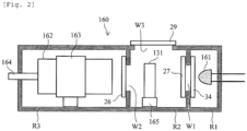
- Fig. 2 is a configuration diagram illustrating the configuration of the detection unit 160 in more detail.
- the detection unit 160 includes three chambers, the first to third chambers R1, R2, R3, connected in series in one direction.
- the second chamber R2 is arranged at a position between the first chamber R1 and the third chamber R3.
- the first to third chambers R1 to R3 are hollow vessels formed entirely of light-shielding walls, and are configured to prevent intrusion of disturbance light and light leakage among the respective chambers R1 to R3. Light from the outside is prevented from reaching the inside. However, a light path is provided across the first to third chambers R1 to R3 so that light can be transmitted and received. That is, a window W1 as a light passage is provided between the first chamber R1 storing the LED 161 and the second chamber R2 storing the reaction vessel 131. The LED 161 is arranged such that a light emission surface of the LED 161 faces the window W1. Light from the LED 161 can reach the reaction vessel 131 via the window W1. Further, a window W2 is provided between the second chamber R2 and the third chamber R3 that stores the photomultiplier tube 162. Light emitted from the reaction vessel 131 can be received by the photomultiplier tube 162 via the window W2.
- the second chamber R2 is provided with a window W3 for inserting or removing the reaction vessel 131.
- the windows W1 to W3 are provided with shutters 26, 27, 29 for blocking the windows W1 to W3, respectively.
- the shutters 26, 27 open the windows W1 and W2 when the photomultiplier tube 162 is inspected so that light of the LED 161 reaches the photomultiplier tube 162.
- the shutter 29 is opened when the reaction vessel 131 is loaded in or evacuated from the second chamber R2, or when a solution is injected into the reaction vessel 131 by the solution injection mechanisms 139, 140, and is closed when an inspection or the like is started.
- Each of the shutters 26, 27, 29 is connected to a stepping motor (not shown) and opens and closes independently according to a control signal from the main controller 171.
- an ND filter 34 is arranged on the window W1 in addition to the shutter 27.
- the ND filter 34 is connected to the main controller 171, and light transmittance of the ND filter 34 can be arbitrarily changed. This makes it possible to adjust the amount of light emitted from the LED 161 so as to prevent damage due to excessive light entering the photomultiplier tube 162.
- the photomultiplier tube 162 is fixed inside the third chamber R3 via the photomultiplier tube holder 163. Moreover, the photomultiplier tube 162 is arranged so that its light receiving surface faces the window W2. A cable 164 is connected to the photomultiplier tube 162, and the cable 164 is led out of the third chamber R3. Then, the photomultiplier tube 162 is connected to the high voltage generator 173 and the logarithmic converter 174 described above via the cable 164. Moreover, a constant voltage power supply (not shown) is connected to the high voltage generator 173. Note that a seal (not shown) is provided between the cable 164 and the third chamber R3 so as to prevent intrusion of disturbance light.
- the second chamber R2 is provided with a reaction vessel holder 165 for detachably holding the reaction vessel 131.
- the reaction vessel holder 165 can include a reaction vessel sensor (not shown) for detecting presence or absence of the reaction vessel 131.
- the shape and structure of the reaction vessel holder 165 are determined based on the reaction vessel 131 used for the immunoassay. Then, as the reaction vessel 131, various general ones such as a test tube, a square cell, a slide plate, a microplate, and a flow cell can be used as the reaction vessel 131.
- terminals of the LED 161 are led out of the first chamber R1, and are held by a wall surface of the first chamber R1.
- the LED 161 is connected to an external power supply (not shown) via the aforementioned constant current source 177, and the amount of light emitted from the LED 161 is adjusted by the constant current source 177.
- a seal (not shown) is provided also between the terminals of the LED 161 and the first chamber R1 to prevent intrusion of disturbance light.
- Various general LEDs can be used as the LED 161.
- the LED 161 one that has at least an emission wavelength that is close to the emission wavelength of a luminescent substance to be subjected to a luminescence reaction with the sample in the reaction vessel 131 is preferable, but it may be configured such that the wavelength is selected by a filter (not shown) different from the LED 161. Furthermore, if optical conditions of the emission wavelength of the luminescent substance and a luminescent component of the LED 161 are arranged in association with each other in advance, it is not necessary to replace the LED 161 for every measurement item, luminescent substance, and the like.
- the reaction vessel 131 is transferred to the second chamber R2 by a reaction vessel transfer unit (not shown), and is mounted on the reaction vessel holder 165.
- a reaction vessel transfer unit (not shown), and is mounted on the reaction vessel holder 165.
- the reaction vessel 131 is transferred to the outside of the second chamber R2 similarly by the reaction vessel transfer unit.
- a general cell loader, a transfer arm, or the like can be used as the reaction vessel transfer unit.
- an injection unit may be incorporated that is configured to inject a substrate solution or the like for causing a luminescence reaction into the reaction vessel 131 held in the reaction vessel holder 165 at an appropriate timing.
- the photomultiplier tube 162 is inspected according to steps S1 to S9 of the flowchart of Fig. 3 . Specifically, the photomultiplier tube 162 is irradiated with reference light (first light) from the LED 161, and it is determined whether the sensitivity of the photomultiplier tube 162 has increased to exceed a reference value (determination upper limit value) from an output signal of the photomultiplier tube 162. If it exceeds the reference value, a procedure for controlling the sensitivity of the photomultiplier tube 162 to an appropriate range is executed according to steps S10 to S21.
- the sensitivity of the photomultiplier tube 162 is reduced, and in a stage that an appropriate value (value equal to or less than a determination lower limit) is obtained, the irradiation with the control light is stopped.
- the sensitivity of the photomultiplier tube 162 can be adjusted in an appropriate range without being restricted by an adjustment range derived from a drive circuit or dark current (without using adjustment of the high voltage value).
- step S1 the main controller 171 detects that the reaction vessel 131 is not installed on the reaction vessel holder 165 of the second chamber R2 based on an output of the reaction vessel sensor (not illustrated) (step S1). If it is installed, the reaction vessel 131 is evacuated from the second chamber R2 using a reaction vessel conveying mechanism (not illustrated) (step S2) .
- the main controller 171 closes the shutter 29 (step S3). Then, the shutter 26 is opened, and a predetermined high voltage is applied to the photomultiplier tube 162 so that the photomultiplier tube 162 is operable (step S4).
- the light emission condition conversion unit 176 sets a current value for emitting the reference light from the LED 161, and the LED 161 is turned on (step S5).
- the reference light is light having a constant intensity that serves as a reference for evaluating sensitivity fluctuation of the photomultiplier tube 162.
- the intensity of the reference light is obtained by setting a predetermined LED current according to the light emission condition determined by the light emission condition conversion unit 176.
- providing the constant current source 177 with a dip switch structured to be switchable among a plurality of resistance values, or the like is conceivable.
- the current value for emitting the reference light is x [A].
- x is, for example, a value of about 0.1 [mA] to about 100 [mA].
- x 3 [mA] as an example.
- the photomultiplier tube 162 detects the reference light.
- the current flowing through the photomultiplier tube 162, that is, a detected current is integrated over a predetermined period of time (for example, 0.4 [s] to 1.0 [s]) by detection, and an amount proportional to the integrated value is determined as a detected light amount in the photomultiplier tube 162.
- the dimension of the detected light amount corresponds to the number of photons.
- the unit of the detected light amount is "count”.
- the initial value means the value of the detected light amount at a certain point that is arbitrarily determined. For example, the light amount of the reference light can be measured immediately after manufacturing the apparatus, immediately after newly attaching the photomultiplier tube 162, or at other timing.
- the main controller 171 stores an initial value X of the detected light amount of the reference light in the storage unit 178 or the like.
- step S5 When light emission of the LED 161 is started in step S5, the main controller 171 opens the shutter 27 and guides the reference light emitted from the LED 161 to the photomultiplier tube 162 (step S6) . Then, the reference light from the LED 161 is detected by the photomultiplier tube 162, and a detected light amount Z [count] is obtained (step S7).
- the main controller 171 compares this detected light amount Z [count] with a predetermined reference value for increase in the sensitivity of the photomultiplier tube 162, that is, a determination upper limit value (U [count]), and determines whether or not Z > U (step S8).
- the determination upper limit value U can be set to a value obtained by multiplying the initial value X described above by a constant. As an example, the determination upper limit value U can be set to 103,000 [counts], which is 3% larger than the initial value X.
- the detected light amount (Z [count]) of the reference light is equal to or smaller than the determination upper limit value U (Z ⁇ U), for example, when it is 101,500 [counts]
- the sensitivity increase of the photomultiplier tube 162 is not zero but is considered allowable or within the range of experimental error, and this flow is ended (step S9) without performing an operation of reducing the sensitivity of the photomultiplier tube 162 (step S10 and thereafter).
- FIG. 4 is a diagram illustrating an example of a typical relationship between light irradiation time and the sensitivity in the photomultiplier tube. As illustrated in Fig. 4 , the sensitivity of the photomultiplier tube generally decreases as the total light irradiation time increases, although there are individual differences. In general, this is also referred to as life characteristics.
- the sensitivity of the photomultiplier tube 162 is reduced by performing light irradiation by utilizing such a property of the photomultiplier tube.
- the amount of reduction in the sensitivity is a function of the output current (anode current) of the photomultiplier tube and varies depending on the type of photomultiplier tube.
- the rate of decrease in the sensitivity of the photomultiplier tube due to light irradiation for one hour from the initial state is -2 [%/hrs.]. Since the anode current of the photomultiplier tube at this time is 70 [uA], the sensitivity reduction rate can also be expressed as -7.9 [%/C] from the relationship between the time and the unit of current. That is, a desired reduction in the sensitivity is achieved by determining the intensity of the control light from the LED 161 so that the output (anode) current amount of the photomultiplier tube is constant with respect to a predetermined incident light, and performing irradiation for a certain period of time.
- step S8 When it is determined that Z > U in step S8, the process proceeds to step S10, and an operation for reducing the increased sensitivity of the photomultiplier tube 162 is started.
- the main controller 171 determines a target light amount of the control light from the LED 161 according to the detected light amount Z of the reference light (step S10).
- the photomultiplier tube 162 is irradiated with control light that causes the anode current of the photomultiplier tube 162 to be 70 [uA] for 7200 [s], that is, 2 hours.
- the target charge amount Y becomes 0.504 [C]. That is, by irradiating the photomultiplier tube 162 with control light with a target light amount corresponding to the target charge amount of 0.504 [C], the target reduction of sensitivity can be reduced.
- a current value y [A] applied to the LED 161, transmittance of the ND filter 34, a distance between the LED 161 and the photomultiplier tube 162, and the like may be appropriately set.
- the current value applied to the LED 161 is adjustable by the light emission condition conversion unit 176.
- Transmittance of the ND filter 34 can be adjusted by the main controller 171.
- the current value y applied to the LED 161 is set to 30 [mA]
- transmittance T of the ND filter is set to 1%
- an anode current value of about 70 [uA] is obtained. Note that it is assumed that the detected light amount corresponding to the anode current value is approximately 1 million [counts].
- the main controller 171 sets the target irradiation time so that the target light amount of the control light is determined.
- the light emission condition conversion unit 176 sets the current value y [A] for emitting the control light from the LED 161, and the LED 161 is turned on for a time determined by the main controller 171 (step S11). At this time, the main controller 171 appropriately stores the total time t' [sec] of irradiation with the control light up to the present toward the set target charge amount Y [C].
- Irradiation with the control light may be performed at any timing other than the timing at which an analysis of the reaction vessel 131 is performed. For example, it is possible to utilize a start-up operation time of the apparatus, an end operation time of the apparatus, and moreover a time in which a preparation operation (for example, reagent dispensing or reagent incubation) for chemiluminescence analysis is performed.
- a preparation operation for example, reagent dispensing or reagent incubation
- the irradiation with the control light can be stopped by an instruction from the user (interruption instruction (step S12)). For example, it is stopped when there is an instruction to shut down the automatic analysis apparatus or to turn off the power, or when the specimen vessel is introduced into the present automatic analysis apparatus and an instruction to perform chemiluminescence analysis is issued, or the like.
- the main controller 171 turns off the LED 161 to interrupt irradiation with the control light, stops applying the high voltage to the photomultiplier tube 162 to turn off the photomultiplier tube 162, and closes the shutters 26 and 27 so as to avoid unnecessary incidence of external light on the photomultiplier tube 162 (step S13).
- the main controller 171 waits for an instruction to resume irradiation with the control light.
- a state in which the control light cannot be irradiated is canceled, that is, when power of the apparatus is turned on again and a start-up operation of the apparatus begins, or when a preparation operation for chemiluminescence analysis (for example, reagent dispensing or reagent incubation) begins, a restart instruction is issued to the main controller 171 (step S14).
- the main controller 171 resumes application of high voltage to the photomultiplier tube 162, and opens the shutters 26, 27 (step S15).
- the main controller 171 adjusts light of the LED 161 so as to have a predetermined amount of control light
- the light emission condition conversion unit 176 sets the current value for emitting the control light from the LED 161, and the LED 161 is turned on (step S11).
- step S16 When the total time t' [sec] of irradiation with the control light for reducing the sensitivity of the photomultiplier tube 162 reaches the target value ty [sec] (step S16), the main controller 171 stops the irradiation with the control light from the LED 161 (step S17). Thereafter, the main controller 171 executes the above-described irradiation with the reference light again to check the sensitivity of the photomultiplier tube 162. That is, similarly to step S5, the light emission condition conversion unit 176 sets the current value for emitting the reference light from the LED 161, and the LED 161 is turned on (step S18).
- the main controller 171 obtains the detected light amount of the photomultiplier tube 162 when the reference light is emitted from the LED 161 (step S19).
- the value of this detected light amount is defined as Z' [count] by the number of photons.
- the main controller 171 compares this detected light amount Z' and a determination lower limit value (L [count]) that is a reference value (target value) for reduction of the sensitivity of the photomultiplier tube 162 (step S20).
- the flow returns to step S10, a necessary amount of the control light is determined again, and irradiation with the control light is performed, so as to reduce the increased sensitivity of the photomultiplier tube 162.
- the sensitivity of the photomultiplier tube 162 is checked again with the reference light, and when the sensitivity is not reduced to the target value, the irradiation with the control light is performed again.
- Such an operation is preferable because the sensitivity can be returned to an appropriate range even in the case described below. That is, it is known that the reduction rate of the sensitivity of the photomultiplier tube 162 with respect to light irradiation not only varies from individual to individual but also varies according to the amount of light irradiation even within the same individual piece.
- the sensitivity may conversely increase due to some other factor. Therefore, there may be cases where the sensitivity is not reduced as expected by irradiation with the control light of an assumed irradiation amount.
- Fig. 5 is a graph showing an example of a relationship between increase and decrease in the sensitivity of the photomultiplier tube 162 along with turning on and off of the control light. Black circle dots in the graph indicate the detected light amount of the photomultiplier tube 162 when irradiated with the reference light.
- the sensitivity of the photomultiplier tube 162 tends to increase, and the sensitivity may exceed the determination upper limit value U.
- the sensitivity of the photomultiplier tube 162 exceeds the determination upper limit value U, irradiation with the control light is started (on) as described in step S8 of Fig.
- the sensitivity of the photomultiplier tube 162 gradually decreases. Also during this irradiation period, after irradiated with a predetermined amount of the control light, the sensitivity of the photomultiplier tube 162 is checked using the reference light (step S20). When an output signal of the photomultiplier tube 162 becomes equal to or lower than the determination lower limit value L, the irradiation with the control light ends, or when the output signal is larger than the determination lower limit value L, the irradiation with the control light is continued.
- the apparatus that uses the chemiluminescence method using acridinium ester as a luminescent label in the detection unit has been described as an example, but the acridinium ester is merely an example.
- Other publicly known method for example, chemiluminescent enzyme immunoassay using luminol, electrochemiluminescence method using ruthenium complex, or bioluminescent enzyme immunoassay using luciferin may be used, and these methods may also be included within the scope of the present invention.
- the amount of the control light is set so that the sensitivity of the photomultiplier tube 162 is controlled to be equal to or less than the determination lower limit value U by irradiation with the control light.
- the sensitivity (absolute value) of the photomultiplier tube 162 is maintained equal to an initial value.
- the automatic analysis apparatus can be used while maintaining the relationship between a signal amount and concentration, that is, precision of a calibration curve, which is originally held as a data table inside the apparatus by the automatic analysis apparatus.
- control of the sensitivity of the photomultiplier tube 162 by irradiation with the control light in the first embodiment is different from the technique of performing preliminary light irradiation before measurement so as to keep the sensitivity of a light receiving sensor constant by aging effect of a light receiving surface, and reduce a warm-up time of the measurement. Specifically, it is different in that whether or not to perform control light irradiation on the photomultiplier tube is appropriately determined according to a detected light amount of the photomultiplier tube when irradiated with the reference light.
- control of the sensitivity of the photomultiplier tube 162 by light irradiation with the control light in the first embodiment is different from a technique of performing a continuous operation for several hours to several tens of hours before use, to thereby reduce the "amount of change" of an output of the photomultiplier tube.
- the present invention is different in that the sensitivity of the photomultiplier tube is controlled within a certain range determined based on a reference value. In this manner, it is possible to maintain quantitativeness of the measurement system.
- the output (anode) current of the photomultiplier tube 162 when irradiated with the reference light can be 1 [uA]
- the output (anode) current of the photomultiplier tube 162 when irradiated with the control light can be 50 [uA].
- the light amount of the reference light may be an average value used in typical analysis of a blood sample, while the light amount of the control light can be a larger value in order to promote a decrease in sensitivity.
- the relationship between the light amount and the sensitivity is not linear. Even in such a region, there is no problem in promoting sensitivity reduction, but when used as a reference light, it is difficult to appropriately detect a change in the sensitivity. Such a problem can be avoided by separating the first light amount and the second light amount.
- the amount of the control light per unit time be 10 times or more the amount of the reference light per unit time (output current or anode current).
- the light amount per unit time of the control light is 50 times the amount of light per unit time of the reference light. In this manner, it is possible to achieve both stability of the reference light and promotion of sensitivity reduction by the control light.
- both the reference light and the control light are generated by one LED 161, and the LED 161 serves as both a light source for the reference light and a light source for the control light.
- the number of light sources and the number of control circuit elements can be saved, and the space can be saved.
- a modification example in which a light source for emitting the reference light and a light source for emitting the control light are provided separately are possible, and such a modification example is also included in the scope of the present invention. By separately providing the light sources for the reference light and the control light, it is easy to adjust the amount of light emitted from each light source.
- the LED that emits the reference light may be an LED having a rated current of about 3 [mA], while the LED that emits the control light may be a high-output LED whose rated current is about 30 [mA].
- the light amount of emitted light has an amount of variation to such an extent that does not pose a practical problem and is negligible.
- an automatic analysis apparatus according to a second embodiment will be described with reference to Figs. 6 and 7 .
- An external appearance of a configuration of the apparatus is identical to that of the first embodiment ( Fig. 1 ), and thus duplicate descriptions will be omitted.
- the second embodiment is different from the first embodiment in an operation of controlling the sensitivity of the photomultiplier tube 162.
- the second embodiment is different from the first embodiment in that, control of the sensitivity of the photomultiplier tube 162 by correcting an electric signal is also performed in addition to control of sensitivity of the photomultiplier tube 162 by irradiation with the control light.
- Fig. 6 is a flowchart showing a procedure for inspecting the photomultiplier tube 162 and controlling its sensitivity as necessary in the automatic analysis apparatus according to the second embodiment.
- Fig. 7 is a conceptual diagram (graph) showing an example of a temporal change in the sensitivity of the photomultiplier tube 162 when the control is performed.
- procedures that are the same as that of the first embodiment ( Fig. 3 ) is given the same reference signs (S1, S2, S3). Thus, duplicate descriptions will be omitted below, and only differences will be described.
- white circle dots in the graph of Fig. 7 indicate the detected light amount of the photomultiplier tube 162 when irradiated with the reference light
- black circle dots indicate the detected light amount of the photomultiplier tube 162 after correction of an electric signal.
- a procedure for controlling the sensitivity of the photomultiplier tube 162 in the automatic analysis apparatus according to the second embodiment is substantially the same in S1 to S9 as that in the first embodiment. However, if it is determined in step S8 that Z ⁇ UL (No), the electric signal is corrected so that the detected light amount of the photomultiplier tube 162 approaches the determination lower limit value L in accordance with the value of Z before ending this flow (step S22).
- a procedure for irradiating the photomultiplier tube 162 with control light is also substantially the same in S10 to S19.
- the second embodiment when it is determined in step S20 that a detected light amount Z' of the photomultiplier tube 162 is larger than the determination lower limit value L (Z' > L), in addition to (or instead of) performing irradiation with the control light again, the obtained detected light amount Z' is corrected as an electric signal (step S23). Consequently, the sensitivity of the photomultiplier tube 162 is electrically corrected so as to have the sensitivity corresponding to the determination lower limit value L.
- the automatic analysis apparatus can be used while maintaining the relationship between a signal amount and concentration, that is, the precision of the calibration curve (master curve) which the automatic analysis apparatus holds internally, in a higher state. Note that if it is determined in step S20 that Z' ⁇ L, that is, if it is determined that the sensitivity of the photomultiplier tube 162 has fallen below the determination lower limit value, a correction to conversely increase the sensitivity is performed (step S24), and thereafter this flow is ended.
- Fig. 7 is a schematic diagram showing a relationship between an increase and a decrease of the sensitivity of the photomultiplier tube 162 along with on and off of the control light, and an electrical correction inside the apparatus.
- white circle dots indicate the detected light amount of the photomultiplier tube 162 when irradiated with the reference light.
- black circle dots are values obtained by correcting the electric signal based on this detected light amount so that the detected light amount becomes equal to the initial value, that is, the detected light amount after correction.
- the numerical (electric signal) correction in steps S22, S23, S24 is such that when the detected light amount of the photomultiplier tube 162 exceeds a numerical correction upper limit value CU (> U) that is even larger than the determination upper limit value U, the signal may be saturated and it may be difficult to correct the signal after the saturation. For this reason, although illustrations in Figs. 6 and 7 are omitted, when the detected light amount Z of the photomultiplier tube 162 exceeds the numerical correction upper limit value CU, it is preferable to execute only the operation of reducing the sensitivity with the control light similarly to the first embodiment, without performing the correction in step S22.
- an automatic analysis apparatus according to a third embodiment will be described with reference to Fig. 8 .
- An external appearance of a configuration of the apparatus is identical to that of the first embodiment ( Fig. 1 ), and thus duplicate descriptions will be omitted.
- the third embodiment differs from the first embodiment in the operation of controlling the sensitivity of the photomultiplier tube 162.
- the third embodiment is configured to use light from a predetermined reagent as reference light for determining the sensitivity of the photomultiplier tube 162, and this point is different from the first embodiment in which the LED 161 emits reference light.
- the third embodiment as shown in Fig.
- the reagent that emits reference light is injected into a reaction vessel 131T, and this reaction vessel 131T is mounted in the second chamber R2 to increase photoelectron intensity, so as to allow emission of the reference light to the photomultiplier tube 162.
- the control light is emitted from the LED 161 as in the first embodiment.
- Fig. 9 is a flowchart showing a procedure for inspecting the photomultiplier tube 162 and controlling the sensitivity thereof as necessary in the automatic analysis apparatus according to the third embodiment. Steps that are the same as those in the first embodiment are given the same reference signs as in Fig. 3 , and duplicate descriptions will be omitted below.
- step S1' the main controller 171 confirms whether or not the reaction vessel 131T containing the reagent for emitting reference light is installed on reaction vessel holder 165 by an arbitrary sensor (not shown). If it is not installed, the reaction vessel 131T is installed on the reaction vessel holder 165 (step S2'). When installation of the reaction vessel 131T' is confirmed, the process proceeds to the next step (step S3). In steps S5', S6, S7', light from the reagent contained in the reaction vessel 131T is radiated toward the photomultiplier tube 162 instead of light emission from the LED 161.
- the detected light amount after the irradiation with the control light is similarly checked using the light from the reagent in the reaction vessel 131T (steps S18', S19'). Note that in addition to the reference light from the reagent in the reaction vessel 131T, it is also possible to radiate the reference light of the LED 161 together to the photomultiplier tube 162.
- a standard sample or a precision control sample which is a calibration sample prepared in advance using a weight or volume outside the automatic analysis apparatus.
- the standard sample and the precision control sample are prepared for the analysis target, such as blood thyroid stimulating hormone, to be actually measured by the system, and are samples routinely used by a user for the purpose of clinical testing.
- the relationship between a signal amount and concentration is generally set for the standard sample and the precision control sample.
- a supplier who provides a clinical test agent provides the sample integrally with the clinical test agent.
- the supplier who provides a clinical test agent to the system provides them. Therefore, when providing standard solutions, for example, of two points, a low-concentration side and a high-concentration side in the manufacturing stage, it is necessary to know in advance how much signal each standard sample produces. Furthermore, the precision control sample is a sample in which an allowable concentration is indicated in advance, and if the apparatus is calibrated with an appropriate standard sample, the signal amount to be output can be predicted. As described above, according to the third embodiment, information regarding the sensitivity of the photomultiplier tube can be obtained from an analysis result of the calibration sample that is regularly used by a user of the automatic analysis apparatus. Furthermore, by using a measurement result of the sample used for calibration of the calibration curve as it is, information can be obtained without using an additional reagent, which is economically efficient.
- step S31 after performing determination of the sensitivity of the photomultiplier tube 162 using the reference light from the LED 161 to obtain a detected light amount Z1 (step S31), determination of the sensitivity of the photomultiplier tube 162 using the reference light from the reagent stored in the reaction vessel 131T is performed to obtain a detected light amount Z2 (step S32). Thereafter, the detected light amount Z1 obtained in step S31 and the detected light amount Z2 obtained in step S32 are each compared with the determination upper limit value U to determine whether or not the two determination results are different (step S33).
- step S34 determines whether or not both Z1, Z2 are larger than the determination upper limit value U is determined. If both Z1, Z2 are equal to or smaller than the determination upper limit value U, this flow is ended. On the other hand, if both Z1, Z2 are larger than the determination upper limit value U, the process proceeds to step S10 in Fig. 9 to control the sensitivity of the photomultiplier tube 162 by irradiation with the control light as in the above-described embodiment.
- warning information is output via the display 179 or the like (step S35).
- the detected light amount measured using the reference light from the reagent in the reaction vessel 131T outputs some kind of abnormal value, it is possible to suspect an abnormality in the reaction vessel 131, the reagent, or the mixing process of the reagent instead of a fluctuation of the sensitivity of the photomultiplier tube 162.
- information regarding the abnormality may be displayed on the display 179 or other display unit of the automatic analysis apparatus.
- a control light irradiation step can be started at an arbitrary timing when the light emission amount of the reaction vessel 131 is not measured.
- the control light irradiation step is preferably performed, for example, when a warm-up operation is performed after starting the automatic analysis apparatus, when a termination processing operation is performed after an instruction to shut down the automatic analysis apparatus is given, or in a standby state waiting for that a specimen vessel to be analyzed is placed in the apparatus.
- a certain time difference can be given between the step of measuring the light emission amount of the reaction vessel 131 and the control light irradiation step.
- the photoelectric surface of the photomultiplier tube is temporarily activated, and it is possible to prevent measurement of the light emission amount of chemiluminescence from being affected.
- the sensitivity of the photomultiplier tube is controlled as described above, it is desirable to display information regarding the sensitivity control on the display 179 or other display unit of the automatic analysis apparatus.
- the information regarding the sensitivity control is, for example,
- an example of "(2) abnormality has been detected while controlling the sensitivity of the photomultiplier tube 162" is a case where a fluctuation larger than normally expected is detected, such as detection of an abnormal value, for example, a detected light amount equal to or more than three times the initial value, at a point that the detected light amount of the photomultiplier tube 162 when irradiated with the reference light is checked.
- a fluctuation larger than normally expected such as detection of an abnormal value, for example, a detected light amount equal to or more than three times the initial value, at a point that the detected light amount of the photomultiplier tube 162 when irradiated with the reference light is checked.
- a fluctuation larger than normally expected such as a value whose standard deviation is abnormal, for example, a value whose ratio to the average value of the detected light amount exceeds 10%.
- the detected light amount is significantly increased after the irradiation with the control light.
- an example of "(3) the upper limit value appropriately set according to control of the sensitivity of the photomultiplier tube 162 has been exceeded” is a case where a total detected light amount (total value of detected light amounts) over the entire period after the photomultiplier tube 162 is installed on the automatic analysis apparatus exceeds a predetermined upper limit value.
- the automatic analysis apparatus according to this embodiment suppresses the sensitivity of the photomultiplier tube 162 by the control light and optimizes the sensitivity. Therefore, the fact that the total detected light amount exceeds a certain upper limit value means that an increase in the sensitivity of the photomultiplier tube 162 occurs continuously.
- Such an automatic analysis apparatus receive maintenance by a person in charge of machine maintenance to check the condition of the apparatus and to replace parts as appropriate, at the stage that the total detected light amount exceeds a certain upper limit value, from the viewpoint of preventing troubles in the future in terms of preventive maintenance.
- Fig. 11 is an example of a display screen of the display 179 after sensitivity control processing in the automatic analysis apparatus according to the embodiment.
- information (Appropriate detection condition.) indicating that the condition of the detection unit is appropriate is displayed.
- the user of the automatic analysis apparatus according to the present embodiment can perform an analysis work after recognizing that the condition of the detection unit is appropriate.
- Fig. 12 is another example of the display screen of the display 179 after the sensitivity control processing of the photomultiplier tube 162 in the automatic analysis apparatus according to the present embodiment.
- This example is of a display that informs the user that an abnormality has been detected in the detection unit during control of the sensitivity of the photomultiplier tube 162 and that maintenance of the automatic analysis apparatus is to be performed (Abnormal detection condition. Please check status of instrument.).
- Abnormal detection condition. Please check status of instrument. the user of the apparatus can recognize that an abnormality has occurred in the detection unit of the automatic analysis apparatus and that it is necessary to check the condition.
Landscapes
- Physics & Mathematics (AREA)
- General Physics & Mathematics (AREA)
- Spectroscopy & Molecular Physics (AREA)
- Engineering & Computer Science (AREA)
- Quality & Reliability (AREA)
- Chemical & Material Sciences (AREA)
- Analytical Chemistry (AREA)
- Life Sciences & Earth Sciences (AREA)
- Health & Medical Sciences (AREA)
- Biochemistry (AREA)
- General Health & Medical Sciences (AREA)
- Immunology (AREA)
- Pathology (AREA)
- Chemical Kinetics & Catalysis (AREA)
- Plasma & Fusion (AREA)
- Investigating Or Analysing Materials By The Use Of Chemical Reactions (AREA)
- Investigating, Analyzing Materials By Fluorescence Or Luminescence (AREA)
- Automatic Analysis And Handling Materials Therefor (AREA)
Applications Claiming Priority (2)
| Application Number | Priority Date | Filing Date | Title |
|---|---|---|---|
| JP2018011947A JP6836522B2 (ja) | 2018-01-26 | 2018-01-26 | 自動分析装置、及び自動分析装置の制御方法 |
| PCT/JP2018/042686 WO2019146227A1 (ja) | 2018-01-26 | 2018-11-19 | 自動分析装置、及び自動分析装置の制御方法 |
Publications (3)
| Publication Number | Publication Date |
|---|---|
| EP3745138A1 EP3745138A1 (en) | 2020-12-02 |
| EP3745138A4 EP3745138A4 (en) | 2021-09-22 |
| EP3745138B1 true EP3745138B1 (en) | 2024-03-13 |
Family
ID=67395377
Family Applications (1)
| Application Number | Title | Priority Date | Filing Date |
|---|---|---|---|
| EP18902928.3A Active EP3745138B1 (en) | 2018-01-26 | 2018-11-19 | Automated analyzer and automated analyzer control method |
Country Status (5)
| Country | Link |
|---|---|
| US (1) | US11499983B2 (ja) |
| EP (1) | EP3745138B1 (ja) |
| JP (1) | JP6836522B2 (ja) |
| CN (1) | CN111373267B (ja) |
| WO (1) | WO2019146227A1 (ja) |
Families Citing this family (2)
| Publication number | Priority date | Publication date | Assignee | Title |
|---|---|---|---|---|
| WO2022009577A1 (ja) * | 2020-07-06 | 2022-01-13 | Look Tec株式会社 | 血液測定装置 |
| JP7417117B2 (ja) | 2021-06-21 | 2024-01-18 | 東亜ディーケーケー株式会社 | 発光分析装置及び発光分析装置の感度調整方法 |
Family Cites Families (21)
| Publication number | Priority date | Publication date | Assignee | Title |
|---|---|---|---|---|
| US4523091A (en) * | 1982-03-22 | 1985-06-11 | Siemens Gammasonics, Inc. | Radiation detecting apparatus with reduced magnetic field sensitivity |
| JP2538338B2 (ja) * | 1989-05-30 | 1996-09-25 | キヤノン株式会社 | 異物検査装置 |
| JPH03120445A (ja) | 1989-10-04 | 1991-05-22 | Hitachi Ltd | 自動蛍光光度測定装置 |
| JPH03132644A (ja) | 1989-10-18 | 1991-06-06 | Fuji Photo Film Co Ltd | 放射線画像読取装置の受光感度較正用ランプ光量調整方法および受光感度較正方法 |
| JPH04168348A (ja) * | 1990-10-31 | 1992-06-16 | Shimadzu Corp | 発光分光分析装置 |
| JPH07159405A (ja) * | 1993-12-06 | 1995-06-23 | Olympus Optical Co Ltd | 光学的免疫測定方法及びこれに用いられる免疫測定装置 |
| JPH09243572A (ja) * | 1996-03-12 | 1997-09-19 | Hitachi Denshi Ltd | 支持体表面検査装置 |
| JPH10311789A (ja) * | 1997-05-13 | 1998-11-24 | Nikon Corp | 測光装置 |
| AU5667499A (en) * | 1998-07-27 | 2000-02-21 | Ljl Biosystems, Inc. | Apparatus and methods for identifying quenching effects in luminescence assays |
| JP2000046734A (ja) | 1998-07-28 | 2000-02-18 | Olympus Optical Co Ltd | 微量光測定装置 |
| JP2001059939A (ja) * | 1999-06-14 | 2001-03-06 | Olympus Optical Co Ltd | フォトマルチプライヤの感度調整方法、該感度調整方法を採用した走査型レーザ顕微鏡および感度調整プログラムを記録した記録媒体 |
| JP2001153799A (ja) * | 1999-11-29 | 2001-06-08 | Shimadzu Corp | 定量分析方法及び定量分析装置 |
| JP4223186B2 (ja) * | 2000-11-17 | 2009-02-12 | 富士フイルム株式会社 | 放射線画像読取方法および装置 |
| JP2008251460A (ja) * | 2007-03-30 | 2008-10-16 | Sony Corp | バックライト装置、バックライト制御方法、および液晶表示装置 |
| JP5124498B2 (ja) | 2009-01-30 | 2013-01-23 | 株式会社日立ハイテクノロジーズ | 自動分析装置 |
| JP2010203776A (ja) | 2009-02-27 | 2010-09-16 | Hitachi High-Technologies Corp | 表面検査装置及びその校正方法 |
| JP2011058984A (ja) * | 2009-09-11 | 2011-03-24 | Hitachi High-Technologies Corp | 異物検査装置,検査方法及びプログラム |
| JP5331673B2 (ja) | 2009-12-28 | 2013-10-30 | 株式会社日立ハイテクノロジーズ | 検査方法及び検査装置 |
| DE102012213494A1 (de) * | 2012-07-31 | 2014-02-06 | Siemens Aktiengesellschaft | Detektion von Röntgenstrahlung und Röntgendetektorsystem |
| JP6171775B2 (ja) | 2013-09-18 | 2017-08-02 | コニカミノルタ株式会社 | イムノアッセイ分析方法およびイムノアッセイ分析装置 |
| US20190346364A1 (en) * | 2016-11-18 | 2019-11-14 | Siemens Healthcare Diagnostics Inc. | Multiple sequential wavelength measurement of a liquid assay |
-
2018
- 2018-01-26 JP JP2018011947A patent/JP6836522B2/ja active Active
- 2018-11-19 CN CN201880075912.1A patent/CN111373267B/zh active Active
- 2018-11-19 WO PCT/JP2018/042686 patent/WO2019146227A1/ja unknown
- 2018-11-19 US US16/956,665 patent/US11499983B2/en active Active
- 2018-11-19 EP EP18902928.3A patent/EP3745138B1/en active Active
Also Published As
| Publication number | Publication date |
|---|---|
| WO2019146227A1 (ja) | 2019-08-01 |
| EP3745138A1 (en) | 2020-12-02 |
| EP3745138A4 (en) | 2021-09-22 |
| US11499983B2 (en) | 2022-11-15 |
| CN111373267A (zh) | 2020-07-03 |
| JP2019128330A (ja) | 2019-08-01 |
| CN111373267B (zh) | 2023-10-24 |
| JP6836522B2 (ja) | 2021-03-03 |
| US20200319218A1 (en) | 2020-10-08 |
Similar Documents
| Publication | Publication Date | Title |
|---|---|---|
| US8628720B2 (en) | Automatic analyzer | |
| EP3745138B1 (en) | Automated analyzer and automated analyzer control method | |
| EP3182096B1 (en) | Calibration and/or error detection in an optical measurement device for biological samples | |
| US8252593B2 (en) | Sample analyzer and calibration method of sample analyzer | |
| EP2857845B1 (en) | Automatic analysis device | |
| CN108572250B (zh) | 确定分析物浓度的方法 | |
| JPH03120445A (ja) | 自動蛍光光度測定装置 | |
| JP2000046734A (ja) | 微量光測定装置 | |
| CN206683758U (zh) | 可调微弱光发生装置 | |
| JP4887319B2 (ja) | 自動分析装置、及び光電子増倍管を用いた分析システム | |
| CN109946323B (zh) | X射线分析装置以及异常检测方法 | |
| US20170138973A1 (en) | Automatic analyzer and method | |
| CN202339327U (zh) | 水质多组分重金属分析仪 | |
| JP2008089450A (ja) | 化学発光測定装置 | |
| US11493430B2 (en) | Automatic analyzer and optical measurement method | |
| US11698352B2 (en) | X-ray fluorescence spectrometer and control method for x-ray fluorescence spectrometer | |
| CA2146498A1 (en) | Fluorescent spectrophotometer system with automatic calibration and improved optics block | |
| CN114812801A (zh) | 一种光子计数装置的校准方法及校准装置 | |
| JP4221282B2 (ja) | 光分析装置及びそれを用いた自動分析装置 | |
| CN114578888A (zh) | 一种光电倍增管增益稳定方法 | |
| CN114137234A (zh) | 血液细胞分析仪的质量控制方法和血液细胞分析仪 | |
| CN111077074A (zh) | 水质分析仪以及紫外线灯劣化判定方法 | |
| JPH08128955A (ja) | ガス濃度計の検査方法およびガス濃度計 |
Legal Events
| Date | Code | Title | Description |
|---|---|---|---|
| STAA | Information on the status of an ep patent application or granted ep patent |
Free format text: STATUS: THE INTERNATIONAL PUBLICATION HAS BEEN MADE |
|
| PUAI | Public reference made under article 153(3) epc to a published international application that has entered the european phase |
Free format text: ORIGINAL CODE: 0009012 |
|
| STAA | Information on the status of an ep patent application or granted ep patent |
Free format text: STATUS: REQUEST FOR EXAMINATION WAS MADE |
|
| 17P | Request for examination filed |
Effective date: 20200615 |
|
| AK | Designated contracting states |
Kind code of ref document: A1 Designated state(s): AL AT BE BG CH CY CZ DE DK EE ES FI FR GB GR HR HU IE IS IT LI LT LU LV MC MK MT NL NO PL PT RO RS SE SI SK SM TR |
|
| AX | Request for extension of the european patent |
Extension state: BA ME |
|
| DAV | Request for validation of the european patent (deleted) | ||
| DAX | Request for extension of the european patent (deleted) | ||
| A4 | Supplementary search report drawn up and despatched |
Effective date: 20210825 |
|
| RIC1 | Information provided on ipc code assigned before grant |
Ipc: G01J 1/44 20060101ALI20210819BHEP Ipc: G01N 35/04 20060101ALI20210819BHEP Ipc: G01N 21/27 20060101ALI20210819BHEP Ipc: G01J 1/42 20060101ALI20210819BHEP Ipc: G01J 1/08 20060101ALI20210819BHEP Ipc: G01J 1/04 20060101ALI20210819BHEP Ipc: G01J 1/02 20060101ALI20210819BHEP Ipc: G01N 35/00 20060101AFI20210819BHEP |
|
| GRAP | Despatch of communication of intention to grant a patent |
Free format text: ORIGINAL CODE: EPIDOSNIGR1 |
|
| STAA | Information on the status of an ep patent application or granted ep patent |
Free format text: STATUS: GRANT OF PATENT IS INTENDED |
|
| INTG | Intention to grant announced |
Effective date: 20231012 |
|
| GRAS | Grant fee paid |
Free format text: ORIGINAL CODE: EPIDOSNIGR3 |
|
| GRAA | (expected) grant |
Free format text: ORIGINAL CODE: 0009210 |
|
| STAA | Information on the status of an ep patent application or granted ep patent |
Free format text: STATUS: THE PATENT HAS BEEN GRANTED |
|
| RIN1 | Information on inventor provided before grant (corrected) |
Inventor name: TAKAKURA TATSUKI, Inventor name: TANOUE, HIDETSUGU Inventor name: YAMASHITA, YOSHIHIRO Inventor name: SAKAZUME, TAKU Inventor name: HAMASAKI, KOSHIN Inventor name: NOBUKI, SHUNICHIROU |
|
| AK | Designated contracting states |
Kind code of ref document: B1 Designated state(s): AL AT BE BG CH CY CZ DE DK EE ES FI FR GB GR HR HU IE IS IT LI LT LU LV MC MK MT NL NO PL PT RO RS SE SI SK SM TR |
|
| REG | Reference to a national code |
Ref country code: GB Ref legal event code: FG4D |
|
| REG | Reference to a national code |
Ref country code: CH Ref legal event code: EP |
|
| REG | Reference to a national code |
Ref country code: DE Ref legal event code: R096 Ref document number: 602018066729 Country of ref document: DE |
|
| REG | Reference to a national code |
Ref country code: IE Ref legal event code: FG4D |