EP3741508B1 - Spitzenlose rundschleifmaschine - Google Patents
Spitzenlose rundschleifmaschine Download PDFInfo
- Publication number
- EP3741508B1 EP3741508B1 EP19175307.8A EP19175307A EP3741508B1 EP 3741508 B1 EP3741508 B1 EP 3741508B1 EP 19175307 A EP19175307 A EP 19175307A EP 3741508 B1 EP3741508 B1 EP 3741508B1
- Authority
- EP
- European Patent Office
- Prior art keywords
- area
- machine
- machine bed
- cylindrical grinding
- centerless cylindrical
- Prior art date
- Legal status (The legal status is an assumption and is not a legal conclusion. Google has not performed a legal analysis and makes no representation as to the accuracy of the status listed.)
- Active
Links
Images

Classifications
-
- B—PERFORMING OPERATIONS; TRANSPORTING
- B24—GRINDING; POLISHING
- B24B—MACHINES, DEVICES, OR PROCESSES FOR GRINDING OR POLISHING; DRESSING OR CONDITIONING OF ABRADING SURFACES; FEEDING OF GRINDING, POLISHING, OR LAPPING AGENTS
- B24B5/00—Machines or devices designed for grinding surfaces of revolution on work, including those which also grind adjacent plane surfaces; Accessories therefor
- B24B5/18—Machines or devices designed for grinding surfaces of revolution on work, including those which also grind adjacent plane surfaces; Accessories therefor involving centreless means for supporting, guiding, floating or rotating work
- B24B5/307—Means for supporting work
-
- B—PERFORMING OPERATIONS; TRANSPORTING
- B24—GRINDING; POLISHING
- B24B—MACHINES, DEVICES, OR PROCESSES FOR GRINDING OR POLISHING; DRESSING OR CONDITIONING OF ABRADING SURFACES; FEEDING OF GRINDING, POLISHING, OR LAPPING AGENTS
- B24B41/00—Component parts such as frames, beds, carriages, headstocks
- B24B41/02—Frames; Beds; Carriages
-
- B—PERFORMING OPERATIONS; TRANSPORTING
- B24—GRINDING; POLISHING
- B24B—MACHINES, DEVICES, OR PROCESSES FOR GRINDING OR POLISHING; DRESSING OR CONDITIONING OF ABRADING SURFACES; FEEDING OF GRINDING, POLISHING, OR LAPPING AGENTS
- B24B41/00—Component parts such as frames, beds, carriages, headstocks
- B24B41/04—Headstocks; Working-spindles; Features relating thereto
-
- B—PERFORMING OPERATIONS; TRANSPORTING
- B24—GRINDING; POLISHING
- B24B—MACHINES, DEVICES, OR PROCESSES FOR GRINDING OR POLISHING; DRESSING OR CONDITIONING OF ABRADING SURFACES; FEEDING OF GRINDING, POLISHING, OR LAPPING AGENTS
- B24B41/00—Component parts such as frames, beds, carriages, headstocks
- B24B41/06—Work supports, e.g. adjustable steadies
-
- B—PERFORMING OPERATIONS; TRANSPORTING
- B24—GRINDING; POLISHING
- B24B—MACHINES, DEVICES, OR PROCESSES FOR GRINDING OR POLISHING; DRESSING OR CONDITIONING OF ABRADING SURFACES; FEEDING OF GRINDING, POLISHING, OR LAPPING AGENTS
- B24B47/00—Drives or gearings; Equipment therefor
- B24B47/02—Drives or gearings; Equipment therefor for performing a reciprocating movement of carriages or work- tables
-
- B—PERFORMING OPERATIONS; TRANSPORTING
- B24—GRINDING; POLISHING
- B24B—MACHINES, DEVICES, OR PROCESSES FOR GRINDING OR POLISHING; DRESSING OR CONDITIONING OF ABRADING SURFACES; FEEDING OF GRINDING, POLISHING, OR LAPPING AGENTS
- B24B47/00—Drives or gearings; Equipment therefor
- B24B47/22—Equipment for exact control of the position of the grinding tool or work at the start of the grinding operation
-
- B—PERFORMING OPERATIONS; TRANSPORTING
- B24—GRINDING; POLISHING
- B24B—MACHINES, DEVICES, OR PROCESSES FOR GRINDING OR POLISHING; DRESSING OR CONDITIONING OF ABRADING SURFACES; FEEDING OF GRINDING, POLISHING, OR LAPPING AGENTS
- B24B49/00—Measuring or gauging equipment for controlling the feed movement of the grinding tool or work; Arrangements of indicating or measuring equipment, e.g. for indicating the start of the grinding operation
- B24B49/12—Measuring or gauging equipment for controlling the feed movement of the grinding tool or work; Arrangements of indicating or measuring equipment, e.g. for indicating the start of the grinding operation involving optical means
-
- B—PERFORMING OPERATIONS; TRANSPORTING
- B24—GRINDING; POLISHING
- B24B—MACHINES, DEVICES, OR PROCESSES FOR GRINDING OR POLISHING; DRESSING OR CONDITIONING OF ABRADING SURFACES; FEEDING OF GRINDING, POLISHING, OR LAPPING AGENTS
- B24B5/00—Machines or devices designed for grinding surfaces of revolution on work, including those which also grind adjacent plane surfaces; Accessories therefor
- B24B5/18—Machines or devices designed for grinding surfaces of revolution on work, including those which also grind adjacent plane surfaces; Accessories therefor involving centreless means for supporting, guiding, floating or rotating work
- B24B5/22—Machines or devices designed for grinding surfaces of revolution on work, including those which also grind adjacent plane surfaces; Accessories therefor involving centreless means for supporting, guiding, floating or rotating work for grinding cylindrical surfaces, e.g. on bolts
-
- B—PERFORMING OPERATIONS; TRANSPORTING
- B24—GRINDING; POLISHING
- B24B—MACHINES, DEVICES, OR PROCESSES FOR GRINDING OR POLISHING; DRESSING OR CONDITIONING OF ABRADING SURFACES; FEEDING OF GRINDING, POLISHING, OR LAPPING AGENTS
- B24B5/00—Machines or devices designed for grinding surfaces of revolution on work, including those which also grind adjacent plane surfaces; Accessories therefor
- B24B5/18—Machines or devices designed for grinding surfaces of revolution on work, including those which also grind adjacent plane surfaces; Accessories therefor involving centreless means for supporting, guiding, floating or rotating work
- B24B5/30—Regulating-wheels; Equipment therefor
-
- B—PERFORMING OPERATIONS; TRANSPORTING
- B24—GRINDING; POLISHING
- B24B—MACHINES, DEVICES, OR PROCESSES FOR GRINDING OR POLISHING; DRESSING OR CONDITIONING OF ABRADING SURFACES; FEEDING OF GRINDING, POLISHING, OR LAPPING AGENTS
- B24B53/00—Devices or means for dressing or conditioning abrasive surfaces
- B24B53/12—Dressing tools; Holders therefor
-
- B—PERFORMING OPERATIONS; TRANSPORTING
- B24—GRINDING; POLISHING
- B24B—MACHINES, DEVICES, OR PROCESSES FOR GRINDING OR POLISHING; DRESSING OR CONDITIONING OF ABRADING SURFACES; FEEDING OF GRINDING, POLISHING, OR LAPPING AGENTS
- B24B55/00—Safety devices for grinding or polishing machines; Accessories fitted to grinding or polishing machines for keeping tools or parts of the machine in good working condition
- B24B55/02—Equipment for cooling the grinding surfaces, e.g. devices for feeding coolant
-
- B—PERFORMING OPERATIONS; TRANSPORTING
- B24—GRINDING; POLISHING
- B24B—MACHINES, DEVICES, OR PROCESSES FOR GRINDING OR POLISHING; DRESSING OR CONDITIONING OF ABRADING SURFACES; FEEDING OF GRINDING, POLISHING, OR LAPPING AGENTS
- B24B55/00—Safety devices for grinding or polishing machines; Accessories fitted to grinding or polishing machines for keeping tools or parts of the machine in good working condition
- B24B55/04—Protective covers for the grinding wheel
Definitions
- the present invention relates to a centerless cylindrical grinding machine for through-feed and plunge-cut grinding of any workpiece according to the preamble of claim 1, such as that in EP 1 330 336 is described.
- continuous and plunge-cut grinding other terms such as continuous or longitudinal grinding and transverse grinding are also used in the literature.
- Centerless cylindrical grinding machines differ from the other cylindrical grinding methods in that the workpiece to be machined is not clamped in the machine or a device, but rests loosely on a base (workpiece support). Compared to other cylindrical grinding processes, centerless grinding enables higher manufacturing accuracy and higher productivity.
- the EP 1 330 336 proposes a centerless cylindrical grinding machine with only three positioning axes. This is made possible by the fact that the proposed centerless cylindrical grinding machine with driven positioning axes X S (or U S ) and X R for adjusting the grinding headstock and the control headstock and another driven positioning axis Y W running at right angles to the axis X R for a slide with a workpiece support on a slide track, the slide can be moved on the carriage track into a position outside of a safety housing and the carriage can be optionally fitted with an internal or an external dressing device.
- the centerless cylindrical grinding machines known from the prior art have in common that the area of the machine bed in which the actual machining of a workpiece takes place is at a distance from the area of the machine bed into which the slideway protrudes is, i.e. the area of the machine bed into which the slideway protrudes must be overcome for access. This makes changing the grinding wheel and/or regulating wheel more difficult, as does accessing components located in this area in general. Equally, however, lateral access to the area of the machine bed into which the slideway protrudes is impeded by the extent of the extension, so that access is essentially limited to a frontal intervention, regardless of other spatial boundary conditions.
- the object of the present invention is, based on this prior art, to further develop a centerless cylindrical grinding machine in such a way that the accessibility of the area of the machine bed in which the grinding headstock and the control headstock are arranged and the area of the machine bed into which the slideway protrudes or is arranged at least in sections, is improved.
- a generic centerless cylindrical grinding machine for through-feed and plunge-cut grinding of any workpieces with a first drivable positioning axis X S for a grinding headstock with a grinding wheel rotatable about a rotational axis and a second drivable positioning axis X R for a control headstock with a rotating axis by one axis of rotation rotatable control wheel and a workpiece support that can be arranged essentially between the grinding headstock and the control headstock, wherein a further positioning axis Y W that can be driven and runs at right angles to at least one of the positioning axes X S and X R for a carriage is mounted on a carriage track, over which the workpiece support can be moved, wherein the grinding headstock and the control headstock are arranged in a first area of a machine bed and the carriage track is arranged at least in sections in a second area of the machine bed is arranged, and the second area of the machine bed in a direction
- the positioning axis X S and the positioning axis X R run parallel to one another, with the axis of rotation of the grinding wheel and the axis of rotation of the regulating wheel being arranged at right angles to the respective positioning axes X S and X R .
- the positioning axis X S can also be arranged inclined with respect to the positioning axis X R . Because of this slope and associated deviation, one associated with "X".
- the positioning axis can also be referred to as the positioning axis U S for better differentiation. For the sake of simplicity, however, both orientations are subsumed under the positioning axis X S .
- the axis of rotation of the grinding wheel can be arranged at right angles to the positioning axis X S , but this is not mandatory.
- the positioning axis Y W is arranged at right angles to one of the positioning axes X S or X R , preferably to the positioning axis X R .
- a fundamental advantage is that the smaller extension of the second area of the machine bed results in at least one open area, which allows for better accessibility for an operator, for example.
- a projection is formed as the second area of the machine bed.
- the carriage track can only be located in this second area of the machine bed if the carriage mounted on it with the workpiece support for the intended machining protrudes sufficiently into the machining area formed between the grinding wheel and the regulating wheel in a movement end position.
- the carriage track can also extend into the second area of the machine bed in order to lengthen the possible travel path, especially if the carriage mounted on it with the workpiece support or the workpiece on the workpiece support does not protrude beyond the carriage track.
- the carriage track extends at least in sections, ie with its end facing away from the machining area, into the second area of the machine bed.
- open areas are preferably formed on both sides of the second area of the machine bed adjoining the first area of the machine bed. Accessibility is increased, particularly with regard to the grinding wheel and regulating wheel, by means of open spaces on both sides.
- the second area of the machine bed preferably extends, starting from the first area of the machine bed, in a direction parallel to the positioning axis Y W at least over a length of the workpiece support in this direction.
- the length of the slideway extending in the second area of the machine bed in the direction of the positioning axis Y W and thus the minimum length of the second area of the machine bed in this direction corresponds at least to the length by which the workpiece support can be moved completely out of the machining area. In this way, workpieces can be taken and repositioned on the workpiece support without having to reach into the processing area.
- the extent of the second area of the machine bed is essentially symmetrical parallel to at least one of the positioning axes X S and X R , starting from a central axis of the carriage track parallel to the positioning axis Y W .
- This enables balanced accessibility on both sides.
- the equal accessibility on both sides increases the flexibility of the machine installation with regard to the given spatial boundary conditions and can offer ergonomic advantages in relation to the operating personnel, since depending on the person, a preferred side of operation, such as left-handed and right-handed people, can be selected for access.
- the term "essentially symmetrical" refers to the basic form of the second area of the machine bed, with smaller contour deviations, such as one through one Switch panel formed projection or an undercut, are negligible in terms of two-sided accessibility.
- the centerless cylindrical grinding machine preferably comprises a movable, in particular pivotable, control panel, which can be moved from one side of the second region of the machine bed running parallel to the positioning axis Y W to the other side in each case.
- the control panel can be moved to the operator's side. If no operation via the control panel is intended, the operator can, for example, also move the panel out of his area of action in order not to be disturbed by the control panel.
- the centerless cylindrical grinding machine includes a first cover that can be moved from a loading position to a protective position and at least partially surrounds the second area of the machine bed, starting from the first area of the machine bed in the protective position.
- the first cover In a loading position, the first cover is in a position in which the cover releases the second area of the machine bed for positioning a workpiece on the workpiece support or at least expands the access option compared to a protective position.
- the loading position is not limited to the positioning of workpieces on the workpiece support, but can equally be used to remove the workpieces or to access components in the first area of the machine bed.
- access to the second area of the machine bed is limited or completely prevented when the first cover is in a protective position.
- the cover does not have to be continuous, but can be formed from individual cover sections. It is possible here to limit the amount of material used, for example by providing the cover sections only in critical safety zones. Cover sections or the first cover as a whole can also have a grid-like or cage-like shape. Individual cover sections can preferably be moved into a loading or protective position independently of one another. The first cover or individual cover sections can be moved manually or driven, in particular automatically depending on the process status, for example automatically moving the first cover into a loading position after the workpiece support has been moved from the processing area to the second area of the machine bed.
- the first cover can be moved perpendicularly to the surface formed by the second area of the machine bed.
- the first cover can be guided in a space-saving manner in the direction of the side walls which adjoin the machine bed and point towards the floor.
- the first cover is particularly preferably guided on the inside in relation to the side walls, ie designed to be at least partially retractable into them. This allows the first cover to be protected.
- the side wall also serves to protect the operator by minimizing moving components in direct contact areas and the associated risk of collision and entrapment.
- the first cover is open at least in sections on a side facing away from the second area of the machine bed in the protective position.
- an opening area opposite the surface formed by the second area of the machine bed is formed.
- the structure of the first cover can be simplified.
- the opening area also offers at a movement blockage of the first cover access options that can also be used for repairs, for example, in such a case.
- the opening area should preferably be in a position such that it is at a sufficient height to at least make access to hazardous areas more difficult or else to prevent it according to usual standards.
- the first cover is preferably at least partially transparent, at least in sections. This makes it possible to see at least partial areas of the second area of the machine bed and thus make it accessible for visual inspection and/or to use optical components for monitoring, documentation or similar purposes, which are also protected by the first cover.
- the centerless cylindrical grinding machine includes a detection unit that detects whether an intervention in a protected area is taking place when the first cover is in a protected position.
- a corresponding detection signal can be used to generate a warning signal and/or to stop the machine in order to counteract a hazardous situation.
- the protection area monitored by the detection unit can be smaller than the area formed by the cover in the protection position.
- the first cover can have a height that makes it easier to prevent access to a lower-lying hazardous area.
- the protection area monitored by the detection unit is limited to the lower-lying danger area.
- the reaction to the detection signal can also vary depending on the definition of threshold values, so that, for example, when using a distance sensor, an acoustic and/or visual warning signal is initially output when a detection signal is present and when the distance falls below a critical value the machine is stopped.
- the centerless cylindrical grinding machine includes a 3D detection unit, which includes at least the area of the protective position of the machine bed. As soon as an object enters the scanning area, a warning signal is generated and/or the machine is stopped to counteract a hazardous situation.
- the first cover In the loading position, the first cover preferably does not essentially protrude over the workpiece support. This enables largely free access to the workpiece support.
- the term "essentially” is therefore to be understood in such a way that the first cover in the loading position does not form any interfering contours for the loading or removal of workpieces that affect the operator's ergonomics or direct access via handling components such as gripper arms.
- the centerless cylindrical grinding machine preferably comprises a second cover which can be moved from an access position into a protective position and which at least partially surrounds the first area of the machine bed.
- the components arranged in the first area of the machine bed such as the grinding headstock and the control headstock, are accessible, as is required, for example, for replacing the grinding wheel or the control wheel.
- the protective position of the second cover prevents or at least limits access to areas from which a risk situation arises.
- the first area of the machine bed is completely closed by the second cover in the protective position against access from the outside.
- in the protective position in the area of the transition between the first area of the machine bed and the second area of the Machine bed remain an opening in the second cover, which allows the movement of the carriage or the workpiece support in and out of the processing area or from the first area to the second area and vice versa.
- the opening is preferably as small as possible, ie in particular adapted to the dimensions of the workpieces that can be moved through the opening on the workpiece support located on the carriage, in order to prevent other interventions or at least to reduce the corresponding possibilities.
- the second cover can be folded. This enables a simple and robust construction of the second cover.
- the first and the second cover do not have to be designed as separate covers.
- the first cover can also form part of the second cover or vice versa.
- embodiments of the first cover with the advantages mentioned thereto can also be transferred to the second cover, regardless of the spatial assignment of the covers, and vice versa.
- the second area of the machine bed can be moved into the first area of the machine bed.
- the length of the projection formed by the second area of the machine bed can be adjusted.
- An unused length for example due to a shortened travel of the carriage for machining or due to non-use of the machine or at least the second area of the machine bed itself, can thus be provided for providing a free space.
- a possibility of moving the second area of the machine bed through the first area for the position-dependent formation of a projection on both sides can allow loading from both sides.
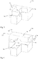
- the centerless cylindrical grinding machine 100 includes a grinding wheel 11 on a grinding headstock 10 which is movable in a first driven positioning axis X S .
- a control wheel 21 on a control headstock 20 is movable in a second driven positioning axis X R .
- the positioning axis X S runs parallel to the positioning axis X R .
- the positioning axes X S and X R are arranged at right angles to the respective axes of rotation 12 , 22 of the grinding wheel 11 and the regulating wheel 21 .
- a workpiece support 32 for a workpiece is arranged between the grinding headstock 10 and the control headstock 20 .
- the workpiece support 32 is located on a carriage 31 which is movable in a carriage track 30 at right angles to the axes X S and X R in a driven positioning axis Y W .
- the workpiece support 32 can be moved out of the danger area of the grinding wheel 11 and the regulating wheel 21 by means of the carriage 31 .
- a dressing device, not shown here, which comprises at least one dressing tool for the grinding wheel 11 and/or regulating wheel 21, and/or a coolant supply can also be arranged on the carriage 31.
- the grinding headstock 10, the control headstock 20 and the carriage 31 on the carriage track 30 are preferably constructed on a machine bed 40, preferably made of thermally stable natural granite.
- the grinding headstock 10 and the control headstock 20 are arranged in a first area 41 of the machine bed 40, while the carriage track 30 extends at least in sections into a second area 42 of the Machine bed 40 protrudes.
- the first area 41 and the second area 42 of the machine bed 40 can be distinguished in that the second area 42 of the machine bed 40 has a smaller extent in a direction parallel to the positioning axis Y W than the first area 41 of the machine bed 40.
- the second area 42 of the machine bed 40 starting from the first area 41 of the machine bed 40, has a projection extending in the direction of the positioning axis Y W . through the in figure 1
- the illustrated second area 42 of the machine bed 40 results in comparison to a centerless cylindrical grinding machine with a consistently wide machine bed on both sides of the gaps, which allow better access to the individual components of the machine.
- the carriage track 30 protrudes in the figure 1 shown configuration as far into the second area 42 of the machine bed 40, so that the carriage 31 with the workpiece support 32 can be moved out of the processing area formed between the grinding wheel 11 and the regulating wheel 21.
- a second cover 70 figure 4
- the carriage 31 and/or the workpiece support 32 can preferably be moved via the carriage track 30 into a position on the side of the second cover 70 facing away from the machining area.
- the second area 42 of the machine bed 40 accordingly has a minimum length in the direction of the positioning axis Y W , which enables the carriage path 30 to be accommodated for the respectively required movement of the carriage 31 or the workpiece support 32 .
- An extension of the second area 42 of the machine bed 40 beyond the minimum length offers the possibility of using the surface created here for the arrangement of further components, such as the in figure 2 illustrated pivotable control panels 50, and / or to use as a shelf.
- control panel 50 supports the use of the open spaces offered by the second region 42 of the machine bed 40 due to the smaller extension on both sides.
- the control panel 50 can be moved about the pivot axis 52 via the pivot arm 51 to the respective preferred side of the operator.
- control panel 50 can also be moved out of the action space provided for this purpose for set-up or repair work.
- first cover 60 In an embodiment of a first cover 60 according to figure 3 this is moved perpendicular to the surface formed by the machine bed 40.
- the first cover 60 runs within the side walls of the second area 42 of the machine bed 40 and the side walls of the first area 41 of the machine bed 40 facing the second area 42 in the direction of the positioning axis YW figure 3
- the position of the first cover 60 shown corresponds to a protective position in which access to the area covered by the first cover 60 is restricted.
- the first cover 60 is open here on a side facing away from the machine bed 40 in the protective position. In other words, lateral protection is provided without the encompassed area being completely encapsulated.
- the swivel arm 51 of the control panel 50 can be arranged in the second area 42 of the machine bed 40 within the first cover 60, with the control panel 50 also being available when the first cover 60 is moved into a protective position.
- a targeted intervention by an operator while at least one accidental intervention is adequately prevented, and/or at least a visual control option is offered.
- a second cover 70 is also provided.
- the first cover 60 is shown here in a loading position in which the first cover 60 has been moved completely into the machine bed 40 .
- the first cover 60 does not form any interference contour.
- the second cover 70 is shown here in a protective position and is designed to be foldable about the first pivot axis 71 and the second pivot axis 72 .
- the second cover 60 encloses the grinding headstock 10 with the grinding wheel 11 and the control headstock 20 with the control wheel 21 in the first region 41 of the machine bed 40 from two sides perpendicular to the surface formed by the machine bed 40, which extends parallel to the positioning axes X S and X R extend, as well as an area formed between these sides on a side facing away from the first region 41 .
- Sections of the second cover 70 can also be formed by other system components, for example a rear wall on the side of the first region 41 of the machine bed 40 facing away from the second region 42.
- the second cover 70 also has an opening 73 on the side surface facing the second area 42 of the machine bed.
- the carriage 31 and the workpiece support 32 together with the workpiece can also be moved through the opening 73 between the first area 41 and the second area 42 of the machine bed 40 when the second cover is in a protective position.
- the opening 73 can be closable, so that the opening 73 is only open for the movement of the carriage or the workpiece support through it.
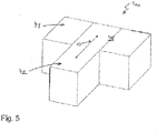
- figure 5 shows a perspective view of the machine bed 40, wherein the second area 42 of the machine bed 40 is movable in and/or through the first region 41 of the machine bed 40 in a direction of movement 43 parallel to the positioning axis Y W .
- the centerless cylindrical grinding machine 100 can also be designed in such a way that the second region 42 with a corresponding movement forms no rear projection.
- the second area 42 can be shortened and/or the first area 41 can have a receptacle for the second area 42 .
- the invention is not limited to the embodiments described. Even if the projection is shown here as a rectangle, the transition can have radii, for example, be tapered, etc.
- the control panel can be moved in a guide along the machine bed. If a swivel arm is provided, it can also come from above.
Landscapes
- Engineering & Computer Science (AREA)
- Mechanical Engineering (AREA)
- Grinding Of Cylindrical And Plane Surfaces (AREA)
- Constituent Portions Of Griding Lathes, Driving, Sensing And Control (AREA)
- Grinding-Machine Dressing And Accessory Apparatuses (AREA)
Priority Applications (7)
| Application Number | Priority Date | Filing Date | Title |
|---|---|---|---|
| EP19175307.8A EP3741508B1 (de) | 2019-05-20 | 2019-05-20 | Spitzenlose rundschleifmaschine |
| ES19175307T ES2921074T3 (es) | 2019-05-20 | 2019-05-20 | Máquina rectificadora cilíndrica sin centros |
| PL19175307.8T PL3741508T3 (pl) | 2019-05-20 | 2019-05-20 | Bezkłowa maszyna szlifierska do powierzchni walcowych |
| US16/875,205 US20200368872A1 (en) | 2019-05-20 | 2020-05-15 | Centerless cylindrical grinding machine |
| JP2020086948A JP7328932B2 (ja) | 2019-05-20 | 2020-05-18 | センタレス円柱研削装置 |
| KR1020200059844A KR102609042B1 (ko) | 2019-05-20 | 2020-05-19 | 센터리스 원통형 연삭기 |
| CN202010425748.1A CN111958342B (zh) | 2019-05-20 | 2020-05-19 | 无心外圆磨床 |
Applications Claiming Priority (1)
| Application Number | Priority Date | Filing Date | Title |
|---|---|---|---|
| EP19175307.8A EP3741508B1 (de) | 2019-05-20 | 2019-05-20 | Spitzenlose rundschleifmaschine |
Publications (2)
| Publication Number | Publication Date |
|---|---|
| EP3741508A1 EP3741508A1 (de) | 2020-11-25 |
| EP3741508B1 true EP3741508B1 (de) | 2022-04-06 |
Family
ID=66625049
Family Applications (1)
| Application Number | Title | Priority Date | Filing Date |
|---|---|---|---|
| EP19175307.8A Active EP3741508B1 (de) | 2019-05-20 | 2019-05-20 | Spitzenlose rundschleifmaschine |
Country Status (7)
| Country | Link |
|---|---|
| US (1) | US20200368872A1 (pl) |
| EP (1) | EP3741508B1 (pl) |
| JP (1) | JP7328932B2 (pl) |
| KR (1) | KR102609042B1 (pl) |
| CN (1) | CN111958342B (pl) |
| ES (1) | ES2921074T3 (pl) |
| PL (1) | PL3741508T3 (pl) |
Families Citing this family (5)
| Publication number | Priority date | Publication date | Assignee | Title |
|---|---|---|---|---|
| CN112692651A (zh) * | 2020-12-30 | 2021-04-23 | 綦江齿轮传动有限公司 | 一种防止小长径比零件跳动的磨削加工方法 |
| CN112589553B (zh) * | 2021-01-07 | 2022-01-04 | 杭州冀新机械制造有限公司 | 一种自动校正砂轮磨损的无心磨床 |
| KR102819511B1 (ko) * | 2023-05-23 | 2025-06-12 | 오알에스코리아 유한회사 | 다축 센터리스 연삭기 |
| KR102656768B1 (ko) | 2024-03-11 | 2024-04-12 | 김승진 | 소형 볼트 연속공급인출형 센터레스 연삭기 |
| CN118513982B (zh) * | 2024-07-23 | 2024-10-08 | 山西恒汇液压高科有限公司 | 一种方便定位的液压配件加工用抛光装置 |
Family Cites Families (25)
| Publication number | Priority date | Publication date | Assignee | Title |
|---|---|---|---|---|
| US1891663A (en) * | 1929-10-16 | 1932-12-20 | Cincinnati Grinders Inc | Grinding machinery |
| US2127210A (en) * | 1937-07-31 | 1938-08-16 | Norton Co | Grinding and lapping machine |
| US2982062A (en) * | 1957-04-02 | 1961-05-02 | Nordberg Manufacturing Co | Method for grinding gyratory crusher wearing parts |
| US3131517A (en) * | 1961-12-13 | 1964-05-05 | Heald Machine Co | Grinding machine |
| US4144676A (en) * | 1975-09-15 | 1979-03-20 | Moll Hans H | Machine tool having frame mounted head and tail stocks |
| US4314425A (en) * | 1980-07-10 | 1982-02-09 | Litton Industrial Products, Inc. | Coolant assembly for a cylindrical grinding machine |
| DE29825161U1 (de) * | 1998-03-27 | 2005-10-06 | Schleifring Service Gmbh | Spitzenlose Rundschleifmaschine |
| CH694940A5 (de) * | 2000-11-03 | 2005-09-30 | Urs Tschudin | Spitzenlose Rundschleifmaschine. |
| JP3878912B2 (ja) | 2003-01-16 | 2007-02-07 | 光洋機械工業株式会社 | センタレス研削盤 |
| DE20314680U1 (de) * | 2003-09-20 | 2003-11-20 | Oerlikon Geartec AG, Zürich | Schleifmaschine mit Messsystem und Steuerung zum Bereitstellen eines Meistermessers |
| US7147542B2 (en) * | 2004-01-02 | 2006-12-12 | Royal Master Grinders, Inc. | Centerless grinder |
| JP2007050457A (ja) | 2005-08-16 | 2007-03-01 | Micron Seimitsu Kk | センタレス研削機のドレッシング装置、及び同ドレッシング方法 |
| JP2007190616A (ja) | 2006-01-17 | 2007-08-02 | Micron Seimitsu Kk | ポータブル無心研削機、及びポータブル方式の無心研削方法 |
| CN2930957Y (zh) * | 2006-05-26 | 2007-08-08 | 新乡市日升数控设备有限公司 | 一种轴承内圈挡边磨床的防护罩 |
| DE202006019304U1 (de) * | 2006-12-21 | 2007-03-15 | Lin, Kun Yi | Bandschleifvorrichtung |
| CN202684664U (zh) * | 2012-07-16 | 2013-01-23 | 广东佳利士汽车零配件制造有限公司 | 缸套无心精磨外圆机构 |
| CN104220215B (zh) * | 2013-03-12 | 2017-10-10 | 新东工业株式会社 | 无心研磨装置 |
| JP5725089B2 (ja) * | 2013-06-11 | 2015-05-27 | 日本精工株式会社 | 研削盤 |
| JP6283559B2 (ja) | 2014-04-22 | 2018-02-21 | 株式会社ディスコ | 加工装置 |
| CN104162819A (zh) * | 2014-08-07 | 2014-11-26 | 陈菊芳 | 双磨头数控端面磨床 |
| DE102014115149B3 (de) * | 2014-10-17 | 2016-01-21 | Schaudt Mikrosa Gmbh | Schleifmaschine, insbesondere kompakt gestaltete spitzenlose Schleifmaschine |
| US10195709B2 (en) * | 2015-02-09 | 2019-02-05 | Glebar Acquisition, Llc | Motorized blade rest apparatus and grinding system with motorized blade rest apparatus |
| JP6453199B2 (ja) * | 2015-10-16 | 2019-01-16 | 光洋機械工業株式会社 | センタレス研削盤 |
| DE102016117915B4 (de) * | 2016-09-22 | 2019-02-14 | Elb-Schliff Werkzeugmaschinen Gmbh | Spindelmodul für eine Werkstückbearbeitungsvorrichtung |
| CN109352357B (zh) * | 2018-09-18 | 2020-05-15 | 东莞市皓晟实业有限公司 | 基于直线电机驱动的模具切削加工中心 |
-
2019
- 2019-05-20 PL PL19175307.8T patent/PL3741508T3/pl unknown
- 2019-05-20 ES ES19175307T patent/ES2921074T3/es active Active
- 2019-05-20 EP EP19175307.8A patent/EP3741508B1/de active Active
-
2020
- 2020-05-15 US US16/875,205 patent/US20200368872A1/en active Pending
- 2020-05-18 JP JP2020086948A patent/JP7328932B2/ja active Active
- 2020-05-19 KR KR1020200059844A patent/KR102609042B1/ko active Active
- 2020-05-19 CN CN202010425748.1A patent/CN111958342B/zh active Active
Also Published As
| Publication number | Publication date |
|---|---|
| ES2921074T3 (es) | 2022-08-17 |
| CN111958342B (zh) | 2022-07-08 |
| JP7328932B2 (ja) | 2023-08-17 |
| PL3741508T3 (pl) | 2022-08-16 |
| JP2020189399A (ja) | 2020-11-26 |
| KR20200134167A (ko) | 2020-12-01 |
| CN111958342A (zh) | 2020-11-20 |
| US20200368872A1 (en) | 2020-11-26 |
| KR102609042B1 (ko) | 2023-12-04 |
| EP3741508A1 (de) | 2020-11-25 |
Similar Documents
| Publication | Publication Date | Title |
|---|---|---|
| EP3741508B1 (de) | Spitzenlose rundschleifmaschine | |
| DE19646189C2 (de) | Maschine zum Herstellen von bogenverzahnten Kegelrädern | |
| DE3732570C2 (pl) | ||
| EP2195140B1 (de) | Poliermaschine für linsen und verfahren zum polieren einer linse mit einer bearbeitungsmaschine | |
| EP3119562B1 (de) | Robotersystem | |
| DE4242906A1 (de) | Numerisch gesteuerte Schleifmaschine zum Schleifen von metallischen Werkstücken, insbesondere Werkzeugen | |
| DE102016209285B3 (de) | Bearbeitungsmaschine mit einem Düsenwechsler | |
| DE60311916T2 (de) | Laserschneidgerät mit zwei Y-Achsantrieben | |
| EP3493935B1 (de) | Innenfräs-maschine | |
| DE202011103226U1 (de) | Werkzeugmaschine | |
| DE69726892T2 (de) | Verbesserungen in Beziehung zu Werkzeugmaschinen | |
| EP2722123B1 (de) | Verfahren zum spanabhebenden Bearbeiten eines Bauteils und Verwendung eines Fluidstrahls | |
| DE102008063513B4 (de) | Bearbeitungszentrum | |
| EP1330336B1 (de) | Spitzenlose rundschleifmaschine | |
| EP2063165A1 (de) | Vorrichtung zur Pendelbearbeitung von Werkstücken | |
| DE10300105A1 (de) | Werkzeugmaschine | |
| EP3849741B1 (de) | Werkzeugmaschine | |
| EP0360953B1 (de) | Maschine zum Feinbearbeiten der Zahnflanken von verzahnten Werkstücken | |
| DE102017127184A1 (de) | Werkstück-Schleuse | |
| EP1755824B1 (de) | Vertikaldrehmaschine mit zwei abwechselnd arbeitenden werkstückspindeln | |
| EP3017910A2 (de) | Drehtisch | |
| DE19902137C1 (de) | Werkzeugmaschine zum Schleifen von Werkstücken | |
| EP4424465B1 (de) | Werkzeugmaschine mit einer verschiebbaren funktionseinrichtung zum scannen oder vor- oder nachbearbeiten von werkstücken sowie zugehöriges verfahren | |
| DE112011103440B4 (de) | Kurbelwellenfräsmaschine | |
| DE102008025385A1 (de) | Palettenaustauscher |
Legal Events
| Date | Code | Title | Description |
|---|---|---|---|
| PUAI | Public reference made under article 153(3) epc to a published international application that has entered the european phase |
Free format text: ORIGINAL CODE: 0009012 |
|
| STAA | Information on the status of an ep patent application or granted ep patent |
Free format text: STATUS: THE APPLICATION HAS BEEN PUBLISHED |
|
| AK | Designated contracting states |
Kind code of ref document: A1 Designated state(s): AL AT BE BG CH CY CZ DE DK EE ES FI FR GB GR HR HU IE IS IT LI LT LU LV MC MK MT NL NO PL PT RO RS SE SI SK SM TR |
|
| AX | Request for extension of the european patent |
Extension state: BA ME |
|
| STAA | Information on the status of an ep patent application or granted ep patent |
Free format text: STATUS: REQUEST FOR EXAMINATION WAS MADE |
|
| 17P | Request for examination filed |
Effective date: 20210518 |
|
| RBV | Designated contracting states (corrected) |
Designated state(s): AL AT BE BG CH CY CZ DE DK EE ES FI FR GB GR HR HU IE IS IT LI LT LU LV MC MK MT NL NO PL PT RO RS SE SI SK SM TR |
|
| GRAP | Despatch of communication of intention to grant a patent |
Free format text: ORIGINAL CODE: EPIDOSNIGR1 |
|
| STAA | Information on the status of an ep patent application or granted ep patent |
Free format text: STATUS: GRANT OF PATENT IS INTENDED |
|
| INTG | Intention to grant announced |
Effective date: 20211029 |
|
| GRAS | Grant fee paid |
Free format text: ORIGINAL CODE: EPIDOSNIGR3 |
|
| GRAA | (expected) grant |
Free format text: ORIGINAL CODE: 0009210 |
|
| STAA | Information on the status of an ep patent application or granted ep patent |
Free format text: STATUS: THE PATENT HAS BEEN GRANTED |
|
| AK | Designated contracting states |
Kind code of ref document: B1 Designated state(s): AL AT BE BG CH CY CZ DE DK EE ES FI FR GB GR HR HU IE IS IT LI LT LU LV MC MK MT NL NO PL PT RO RS SE SI SK SM TR |
|
| REG | Reference to a national code |
Ref country code: GB Ref legal event code: FG4D Free format text: NOT ENGLISH |
|
| REG | Reference to a national code |
Ref country code: CH Ref legal event code: EP |
|
| REG | Reference to a national code |
Ref country code: AT Ref legal event code: REF Ref document number: 1480863 Country of ref document: AT Kind code of ref document: T Effective date: 20220415 |
|
| REG | Reference to a national code |
Ref country code: IE Ref legal event code: FG4D Free format text: LANGUAGE OF EP DOCUMENT: GERMAN |
|
| REG | Reference to a national code |
Ref country code: DE Ref legal event code: R096 Ref document number: 502019003928 Country of ref document: DE |
|
| REG | Reference to a national code |
Ref country code: SE Ref legal event code: TRGR |
|
| REG | Reference to a national code |
Ref country code: LT Ref legal event code: MG9D |
|
| REG | Reference to a national code |
Ref country code: NL Ref legal event code: MP Effective date: 20220406 |
|
| REG | Reference to a national code |
Ref country code: ES Ref legal event code: FG2A Ref document number: 2921074 Country of ref document: ES Kind code of ref document: T3 Effective date: 20220817 |
|
| PG25 | Lapsed in a contracting state [announced via postgrant information from national office to epo] |
Ref country code: NL Free format text: LAPSE BECAUSE OF FAILURE TO SUBMIT A TRANSLATION OF THE DESCRIPTION OR TO PAY THE FEE WITHIN THE PRESCRIBED TIME-LIMIT Effective date: 20220406 |
|
| PG25 | Lapsed in a contracting state [announced via postgrant information from national office to epo] |
Ref country code: PT Free format text: LAPSE BECAUSE OF FAILURE TO SUBMIT A TRANSLATION OF THE DESCRIPTION OR TO PAY THE FEE WITHIN THE PRESCRIBED TIME-LIMIT Effective date: 20220808 Ref country code: NO Free format text: LAPSE BECAUSE OF FAILURE TO SUBMIT A TRANSLATION OF THE DESCRIPTION OR TO PAY THE FEE WITHIN THE PRESCRIBED TIME-LIMIT Effective date: 20220706 Ref country code: LT Free format text: LAPSE BECAUSE OF FAILURE TO SUBMIT A TRANSLATION OF THE DESCRIPTION OR TO PAY THE FEE WITHIN THE PRESCRIBED TIME-LIMIT Effective date: 20220406 Ref country code: HR Free format text: LAPSE BECAUSE OF FAILURE TO SUBMIT A TRANSLATION OF THE DESCRIPTION OR TO PAY THE FEE WITHIN THE PRESCRIBED TIME-LIMIT Effective date: 20220406 Ref country code: GR Free format text: LAPSE BECAUSE OF FAILURE TO SUBMIT A TRANSLATION OF THE DESCRIPTION OR TO PAY THE FEE WITHIN THE PRESCRIBED TIME-LIMIT Effective date: 20220707 Ref country code: FI Free format text: LAPSE BECAUSE OF FAILURE TO SUBMIT A TRANSLATION OF THE DESCRIPTION OR TO PAY THE FEE WITHIN THE PRESCRIBED TIME-LIMIT Effective date: 20220406 Ref country code: BG Free format text: LAPSE BECAUSE OF FAILURE TO SUBMIT A TRANSLATION OF THE DESCRIPTION OR TO PAY THE FEE WITHIN THE PRESCRIBED TIME-LIMIT Effective date: 20220706 |
|
| PG25 | Lapsed in a contracting state [announced via postgrant information from national office to epo] |
Ref country code: RS Free format text: LAPSE BECAUSE OF FAILURE TO SUBMIT A TRANSLATION OF THE DESCRIPTION OR TO PAY THE FEE WITHIN THE PRESCRIBED TIME-LIMIT Effective date: 20220406 Ref country code: LV Free format text: LAPSE BECAUSE OF FAILURE TO SUBMIT A TRANSLATION OF THE DESCRIPTION OR TO PAY THE FEE WITHIN THE PRESCRIBED TIME-LIMIT Effective date: 20220406 Ref country code: IS Free format text: LAPSE BECAUSE OF FAILURE TO SUBMIT A TRANSLATION OF THE DESCRIPTION OR TO PAY THE FEE WITHIN THE PRESCRIBED TIME-LIMIT Effective date: 20220806 |
|
| REG | Reference to a national code |
Ref country code: DE Ref legal event code: R097 Ref document number: 502019003928 Country of ref document: DE |
|
| REG | Reference to a national code |
Ref country code: BE Ref legal event code: MM Effective date: 20220531 |
|
| PG25 | Lapsed in a contracting state [announced via postgrant information from national office to epo] |
Ref country code: SM Free format text: LAPSE BECAUSE OF FAILURE TO SUBMIT A TRANSLATION OF THE DESCRIPTION OR TO PAY THE FEE WITHIN THE PRESCRIBED TIME-LIMIT Effective date: 20220406 Ref country code: SK Free format text: LAPSE BECAUSE OF FAILURE TO SUBMIT A TRANSLATION OF THE DESCRIPTION OR TO PAY THE FEE WITHIN THE PRESCRIBED TIME-LIMIT Effective date: 20220406 Ref country code: RO Free format text: LAPSE BECAUSE OF FAILURE TO SUBMIT A TRANSLATION OF THE DESCRIPTION OR TO PAY THE FEE WITHIN THE PRESCRIBED TIME-LIMIT Effective date: 20220406 Ref country code: MC Free format text: LAPSE BECAUSE OF FAILURE TO SUBMIT A TRANSLATION OF THE DESCRIPTION OR TO PAY THE FEE WITHIN THE PRESCRIBED TIME-LIMIT Effective date: 20220406 Ref country code: LU Free format text: LAPSE BECAUSE OF NON-PAYMENT OF DUE FEES Effective date: 20220520 Ref country code: EE Free format text: LAPSE BECAUSE OF FAILURE TO SUBMIT A TRANSLATION OF THE DESCRIPTION OR TO PAY THE FEE WITHIN THE PRESCRIBED TIME-LIMIT Effective date: 20220406 Ref country code: DK Free format text: LAPSE BECAUSE OF FAILURE TO SUBMIT A TRANSLATION OF THE DESCRIPTION OR TO PAY THE FEE WITHIN THE PRESCRIBED TIME-LIMIT Effective date: 20220406 |
|
| PLBE | No opposition filed within time limit |
Free format text: ORIGINAL CODE: 0009261 |
|
| STAA | Information on the status of an ep patent application or granted ep patent |
Free format text: STATUS: NO OPPOSITION FILED WITHIN TIME LIMIT |
|
| 26N | No opposition filed |
Effective date: 20230110 |
|
| PG25 | Lapsed in a contracting state [announced via postgrant information from national office to epo] |
Ref country code: AL Free format text: LAPSE BECAUSE OF FAILURE TO SUBMIT A TRANSLATION OF THE DESCRIPTION OR TO PAY THE FEE WITHIN THE PRESCRIBED TIME-LIMIT Effective date: 20220406 |
|
| PG25 | Lapsed in a contracting state [announced via postgrant information from national office to epo] |
Ref country code: IE Free format text: LAPSE BECAUSE OF NON-PAYMENT OF DUE FEES Effective date: 20220520 |
|
| PG25 | Lapsed in a contracting state [announced via postgrant information from national office to epo] |
Ref country code: SI Free format text: LAPSE BECAUSE OF FAILURE TO SUBMIT A TRANSLATION OF THE DESCRIPTION OR TO PAY THE FEE WITHIN THE PRESCRIBED TIME-LIMIT Effective date: 20220406 Ref country code: BE Free format text: LAPSE BECAUSE OF NON-PAYMENT OF DUE FEES Effective date: 20220531 |
|
| GBPC | Gb: european patent ceased through non-payment of renewal fee |
Effective date: 20230520 |
|
| PG25 | Lapsed in a contracting state [announced via postgrant information from national office to epo] |
Ref country code: MK Free format text: LAPSE BECAUSE OF FAILURE TO SUBMIT A TRANSLATION OF THE DESCRIPTION OR TO PAY THE FEE WITHIN THE PRESCRIBED TIME-LIMIT Effective date: 20220406 Ref country code: CY Free format text: LAPSE BECAUSE OF FAILURE TO SUBMIT A TRANSLATION OF THE DESCRIPTION OR TO PAY THE FEE WITHIN THE PRESCRIBED TIME-LIMIT Effective date: 20220406 Ref country code: GB Free format text: LAPSE BECAUSE OF NON-PAYMENT OF DUE FEES Effective date: 20230520 |
|
| PG25 | Lapsed in a contracting state [announced via postgrant information from national office to epo] |
Ref country code: HU Free format text: LAPSE BECAUSE OF FAILURE TO SUBMIT A TRANSLATION OF THE DESCRIPTION OR TO PAY THE FEE WITHIN THE PRESCRIBED TIME-LIMIT; INVALID AB INITIO Effective date: 20190520 |
|
| PG25 | Lapsed in a contracting state [announced via postgrant information from national office to epo] |
Ref country code: MT Free format text: LAPSE BECAUSE OF FAILURE TO SUBMIT A TRANSLATION OF THE DESCRIPTION OR TO PAY THE FEE WITHIN THE PRESCRIBED TIME-LIMIT Effective date: 20220406 |
|
| PG25 | Lapsed in a contracting state [announced via postgrant information from national office to epo] |
Ref country code: BG Free format text: LAPSE BECAUSE OF FAILURE TO SUBMIT A TRANSLATION OF THE DESCRIPTION OR TO PAY THE FEE WITHIN THE PRESCRIBED TIME-LIMIT Effective date: 20220406 |
|
| PG25 | Lapsed in a contracting state [announced via postgrant information from national office to epo] |
Ref country code: BG Free format text: LAPSE BECAUSE OF FAILURE TO SUBMIT A TRANSLATION OF THE DESCRIPTION OR TO PAY THE FEE WITHIN THE PRESCRIBED TIME-LIMIT Effective date: 20220406 |
|
| PGFP | Annual fee paid to national office [announced via postgrant information from national office to epo] |
Ref country code: PL Payment date: 20241105 Year of fee payment: 6 |
|
| REG | Reference to a national code |
Ref country code: AT Ref legal event code: MM01 Ref document number: 1480863 Country of ref document: AT Kind code of ref document: T Effective date: 20240520 |
|
| PG25 | Lapsed in a contracting state [announced via postgrant information from national office to epo] |
Ref country code: AT Free format text: LAPSE BECAUSE OF NON-PAYMENT OF DUE FEES Effective date: 20240520 |
|
| PGFP | Annual fee paid to national office [announced via postgrant information from national office to epo] |
Ref country code: CH Payment date: 20250901 Year of fee payment: 7 |
|
| PGFP | Annual fee paid to national office [announced via postgrant information from national office to epo] |
Ref country code: DE Payment date: 20251030 Year of fee payment: 7 |
|
| PGFP | Annual fee paid to national office [announced via postgrant information from national office to epo] |
Ref country code: IT Payment date: 20251030 Year of fee payment: 7 |
|
| PGFP | Annual fee paid to national office [announced via postgrant information from national office to epo] |
Ref country code: FR Payment date: 20251031 Year of fee payment: 7 |
|
| PGFP | Annual fee paid to national office [announced via postgrant information from national office to epo] |
Ref country code: TR Payment date: 20251103 Year of fee payment: 7 |
|
| PGFP | Annual fee paid to national office [announced via postgrant information from national office to epo] |
Ref country code: SE Payment date: 20251030 Year of fee payment: 7 |
|
| PGFP | Annual fee paid to national office [announced via postgrant information from national office to epo] |
Ref country code: CZ Payment date: 20251030 Year of fee payment: 7 |
|
| PGFP | Annual fee paid to national office [announced via postgrant information from national office to epo] |
Ref country code: ES Payment date: 20251031 Year of fee payment: 7 |