US1891663A - Grinding machinery - Google Patents
Grinding machinery Download PDFInfo
- Publication number
- US1891663A US1891663A US400136A US40013629A US1891663A US 1891663 A US1891663 A US 1891663A US 400136 A US400136 A US 400136A US 40013629 A US40013629 A US 40013629A US 1891663 A US1891663 A US 1891663A
- Authority
- US
- United States
- Prior art keywords
- work
- grinding
- throat
- movement
- valve
- Prior art date
- Legal status (The legal status is an assumption and is not a legal conclusion. Google has not performed a legal analysis and makes no representation as to the accuracy of the status listed.)
- Expired - Lifetime
Links
- 230000007246 mechanism Effects 0.000 description 28
- 230000001105 regulatory effect Effects 0.000 description 27
- 230000000694 effects Effects 0.000 description 14
- 230000001276 controlling effect Effects 0.000 description 9
- 230000008878 coupling Effects 0.000 description 4
- 238000010168 coupling process Methods 0.000 description 4
- 238000005859 coupling reaction Methods 0.000 description 4
- 238000004519 manufacturing process Methods 0.000 description 4
- 230000008859 change Effects 0.000 description 3
- 230000000994 depressogenic effect Effects 0.000 description 3
- 125000004122 cyclic group Chemical group 0.000 description 2
- 239000012530 fluid Substances 0.000 description 2
- 230000002441 reversible effect Effects 0.000 description 2
- 230000001360 synchronised effect Effects 0.000 description 2
- 241000251468 Actinopterygii Species 0.000 description 1
- 229910000831 Steel Inorganic materials 0.000 description 1
- 230000015572 biosynthetic process Effects 0.000 description 1
- 230000001419 dependent effect Effects 0.000 description 1
- 230000000977 initiatory effect Effects 0.000 description 1
- 238000003780 insertion Methods 0.000 description 1
- 230000037431 insertion Effects 0.000 description 1
- 230000001788 irregular Effects 0.000 description 1
- 239000000463 material Substances 0.000 description 1
- 239000002184 metal Substances 0.000 description 1
- 238000000034 method Methods 0.000 description 1
- 238000012986 modification Methods 0.000 description 1
- 230000004048 modification Effects 0.000 description 1
- 230000010355 oscillation Effects 0.000 description 1
- 230000000306 recurrent effect Effects 0.000 description 1
- 230000000452 restraining effect Effects 0.000 description 1
- 239000010959 steel Substances 0.000 description 1
Images

Classifications
-
- B—PERFORMING OPERATIONS; TRANSPORTING
- B24—GRINDING; POLISHING
- B24B—MACHINES, DEVICES, OR PROCESSES FOR GRINDING OR POLISHING; DRESSING OR CONDITIONING OF ABRADING SURFACES; FEEDING OF GRINDING, POLISHING, OR LAPPING AGENTS
- B24B5/00—Machines or devices designed for grinding surfaces of revolution on work, including those which also grind adjacent plane surfaces; Accessories therefor
- B24B5/18—Machines or devices designed for grinding surfaces of revolution on work, including those which also grind adjacent plane surfaces; Accessories therefor involving centreless means for supporting, guiding, floating or rotating work
- B24B5/24—Machines or devices designed for grinding surfaces of revolution on work, including those which also grind adjacent plane surfaces; Accessories therefor involving centreless means for supporting, guiding, floating or rotating work for grinding conical surfaces
Definitions
- This invention relates to improvements in grinding machinery and has particular refrence to a machine especially adapted for .use in the grinding of relatively long Work pieces.
- One of the principal objects of the present invention is the provision of a machine which may be satisfactorily employed in the formation by'grindingof tapered surfaces and particularly tapered surfaces on work pieces of apprciable length such asrifle barrels. golf club shafts or the like..
- An additional object of the present inven'- tion is the provision of mechanisms which may be utilized to produce a controlled va'- riable taper longitudinally of the work piece togetheriif desired with a reverse taper or configuration at the terminal portion thereof.
- ⁇ A further obj ect of the invention isthe provision of an improved control mechanism readily applicable to standard forms of machines such as centerless grinders for examp'le which will satisfactorily coordinate and control-the rate of movement of a workpiece past the grinding member with respect to the rate of relative feeding movement determining the stock removal and in which one of said rates may be automatically' varied in recurrent cycle duringsuccessive grinding. 3. operations.
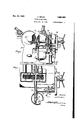
- Figure 1 is a. front elevation o f a machine embodying the invention.
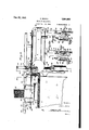
- Figure 2. is a fragmentary plan lView thereof.
- Figure 3 is a transverse section through the' machine,- With the work -movement controlling mechanism illustrated in elevation'.
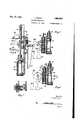
- Figure 4 is a vertical section on the line 1 operatingpiston, the hydraulic,circuitibeing diagrammatically indicated.
- Figure 5A is a fragmentary plan view of the operatingl lever ,and parts associated therewith illustrating the relative positions thereof when the valve is shiftedto the position shown in Figure 5,
- Figure 6 is a view similar to Figure 5 il- Y lustrating a different valve position..
- Figure 6A is a view similar to Figure 5A showingA the relative positions of the parts when the valve is in the position of Figure 6.
- Figure 7 is a section-through the valve lever detent and associate keeper member.
- Figure 8 is a section through the feed screw gear box mechanism with associate parts shown in elevation, taken as on the line 8-8 of Figure 1.
- Figure 9 is a view similar to Figure 3,'illustrating a variable work traverse control mechanism.
- Figure 10 is a transverse section through thework feed lcontrol mechanism,'taken as on thel line 10--10 of Figure.
- Figure 11 is a sectional view on line 11-11 of Figure 6.
- the present invention contemplates .the
- the machine illustrated comprises a bed l'having the -iournal 16 for the spindle of Athe* grinding wheel 17 rotatable at a high 'grinding rate of speed'in a clockwise direction, the bed 15 further Aserving as a support swiveled thereto the bracket 20 bearing the regulating wheel 21 rotatable at a slow work controlling speed in a clockwise direction and angleable to any position to effect the desired fced component or retardance thrust depending upon the particular' method of operation of machine being utilized.
- Swiveled in a bracket 22 carried by the bed is an adjusting screw 23 fitting within a sleeve nut 24 rotatably supported by the regulating wheel unit 19.
- Rotation of screw 23 will therefore impart an in and out adjusting movement to the regulating wheel unit 19 while similarly a rotation of sleeve nut 24 about the screw will effect a corresponding adjustment.
- the sleeve nut is provided with a pinion portion 25 meshing -with gear 26 ofthe change gear series 26, 27, and 28 for effecting a suitable actuation of nut 24 for in and outmovement of the regulating'wheel unit.
- Slide 18 supports what may be termed as a work rest assembly including a bracket portion 29 having mounted thereon a work rest blade 30 projecting into the space between the wheels 17 and 21.
- Member 29 also carries the V-shaped supports 32 and 33 for the work guide plates 34 and 35 forming troughs for reception of an elongated work piece such as the golf club shaft 36. ⁇
- the member 29 is additionally provided with a guide passage as at 37 for slide rod 38 carrying the end stop ejector member 39 and the the work feeding member 40, these members riding respectively in slots 41 between the pairs of guide plates and 34 respectively, as it will be best understood by reference to Figure 10.
- bracket 48 Secured to the bed of the machine is a bracket 48 including a cylinder 49 having reciprocable therein a piston 50 having a projecting rod 51 provided with a rack 52 for operation of pinion 53 mounted onspline shaft 54.
- the cylinder 49 Formed in the bracket member 48 adjacent ,the cylinder 49 are a pair of passa-ges 52 and 53 communicating respectively with the upper and lower ends of the cylinder.
- the bracket is also formed with a chamber 54 having a ported bushing 55 containing the control valve 56.
- the bushing has an inlet as at 57 coupled through conduit 43 with pump 42 for reception of actuating fiuid and has the discharge outlet 58 coupled direct by conduit 44 withv the reservoir and a second ldischarge outlet 59 coupled through conduit 45 and adjustable choke valve 60 with the reservoir.
- the bushing has outlet port 61 coupled through passage 52 with the upper end of the cylinder and ports 63 and 64 cou pledl by passage 53' with the lower end of the cylinder.
- a plunger valve member Disposed within the bushing is a plunger valve member designated as an entirety by the numeral 65 having cannelures as at 66, 67, 68 and 69 adapted to selectively join or couple certain of the inlet and outlet ports of the bushing to determine the rate and direction of flow of the actuating medium into and out of the piston controlling cylinder.
- the valve 65 is adapted to occupy three different positions. In its depressed position as indicated in Figure 5 the How is from the pump through conduit 43 port 57, cannelure 67, port 61 and passage 52 through the upper end of the cylinder urging the piston downward. At this time the hydraulic actuating medium contained in the lower portion of the cylinder will be discharged through port 64, cannelure 68, port 58 and conduit 44 to the tank. It will beA noted that this will be an 11n-restricted flow of the exhaust fluid and that consequently the piston may move at a rapid rate.
- FIG. 6 A second position of the valve is illustrated in Figure 6. In this position the fiow from the pump as before passes out through port 61 to the upper end of the cylinder. The valve has been raised however, from a position where the flow from port 64 passes around cannelure 68 and in its place the fiow is around cannelure 69. discharge port 59 and conduit 45 including the choke valve 60. Adjustment of this choke valve serves to variably determine ,the rate of discharge of the compressed or exhaust fiuid and thus slows down the movement of the piston producing a feeding as distinguished from quick traverse movement of the parts.
- valve positions which in connection one with the other serve to effect variable rates of movement of the piston according to the setting of the valve, but should additional rates of movement be desired it is merely necessary to provide additional portings in connection with suitable valve positions for variably connecting selected ports with suitable choke or control of thc additional circuits thus utilized.
- valve is attained by a substantially automatic- A mechanism including a setting handle and a control cam therefor.
- supports 70 carrying' a bracket 71 on the face of which are adjustably mounted as by bolts 72.
- the cam plate 73 having the respective portions 74, 75 and 76.
- Bracket 48 has a lateral extension 77 to which is pivoted the control lever 78 having an integral depending arm 79 provided lwith ,a spring pressed ⁇ latch 80. kDepression of the handle portion of lever 78 to the position shown in Figure' 5A causes the latch 80 to snap over the cam plate and engage with the contoured side 74 thereof securing the lever in depressed position against the tension of its actuating spring 80.
- Suitable adjustable stops 81 and 82 are disposed to terminally engage the lever and limit its oscillations.
- the lever itself has suitable pivotal connections as at 83 with the upper end of valve stem rod 84 with the result that when the lever is depressed the valve will be shifted to its low-ermost position as shown in Figure 5 initiating a rapid downward movement of piston 50.
- the grinding wheel is illustrated as formed with a contoured face comprising a rounded forward portion as at y85 and a reversely tapered portion asat 86.
- the regulating wheel preferably' bears a contoured forward portion at 87 and tapered rear section at 88.
- the regulating wheel may either be set with its axis parallel to that of the grinding wheel so that no feed component is introduced or may have its axis tilted to-introduce a feed component urging the work into the throat in correspondence with the movement of the work carriage or holding the work back against the pusher member 40 according to preference or the particular type of work being ground.
- the mechanism .4in question is adapted for 'grinding various articles -of varying materials such 'aslong steel fish poles, wooden golfclub shafts or the like.
- the 'angled .taper between grinding and regulating wheels is preferably that to be reproduced on the work asthe truing of the wheel is thereby reduced' to a minimum.
- the operation is s uch that the rate of diminution of the throat and the rate 'of traverse movementv of the work iny a' direction through the throatv maintainaconstant en'- gagement ofthe grindingand regulating wheels throughout the extent of their tapered portion withthe work as the same progresses from large to small end or from v ⁇ small to ylarge depending on whether the screw and nut effect narrowing or widening of the throat during the grinding operation.
- Ultimately downward movement of piston rod 5l and cam 7 3 carried thereby will move the cam past the keeper allowing the lever to snap upward to a ⁇ position limited by engagement of stop 8l therewith.
- the rate of 4movement of the work piece will be a Variable one. This is partlcularly'advantageous in the grinding of non-metallic articles where wear of the grinding wheel may be substantlally diereg'aided and the taper determined by the rela-I tive rate-s of infeeding and ⁇ traversing movenient-s. The faster the rate of tra-verse of the'V work as respects a given rate of infeed movement the more gradual the taper produced on the work while the slower the travel of the work the greater the taper thereon.
- a machine of the character described tor grinding circular contoured articles including a bed or support, opposed grinding and regulating wheels carried thereby to provide a Work receiving throat therebetween, said wheels being operable respectively at a high grinding rate of speed to effect a stock removal from the work and at a relatively slow work controlling rate of speed, a work support sub-tending the throat relative to which the work is shifted, means for varylng the width of the grinding throat, means for feeding the work piece along said work support and means for simultaneously effecting the actuation of the throat varying and work feeding mechanisms.
- a machine of the character describedfor grinding circular contoured articles including opposed grinding and regulating wheels forming a Work receiving throat therebetween, means or su porting a work piece within the throat relatlve to which the work is shited, means for longitudinally shifting the work piece along the support, and coupled means for varying the width of throat during said longitudinal shifting.
- a machine of the character described including opposed grinding and regulating wheels forming a work receiving throat therebetween, means for supporting a work piece within the throat, means for longitudinally shifting a work piece along the support, coupled means for varying the width of throat during said longitudinal shifting, said means including prime mover and power connections from the prime mover to the throat varying and work shifting means.
- a machine of the character described including opposed grinding and regulating wheels forming a work receiving throat therebetween, means for supporting a work piece within the throat, means for longitudinally shifting a work piece along the support, coupled means for varying the width of throat during said longitudinal shifting, said means including a prime mover, power connections from the-prime mover to the throat varying and Work shifting means, and means for causing simultaneous reverse shifting of the parts.
- a machine for the purpose described including opposed grinding and regulating wheels forming a work receiving throat therebetween, means for supporting and transversely shifting a work piece Within the throat, additional means for varying the v width of throat during operative engagement of a work piece therein andan hydraulic actuator for simultaneously effecting the Work shi fting and throat varying movements.
- a machine for the purpose described including opposed grinding and regulating wheels forming a work receiving throat therebetween, means for supporting and transversely shifting a work piece within the throat, additional means for varying the width of throat duringoperative engagement of a work piece therein, an hydraulic actuator for simultaneously effecting the Work shifting and throatl varying movements, an hydraulic circuit for the actuator and a variably adjustable valve effective to determine the operative coupling of the circuit with the actuator.
- a machine for the purpose described including opposed grinding and regulating Wheels forming a work receiving throat therebetween, means for supporting and transversely shifting a work piece within the throat, additional means for varying the width of throat during operative engagement ofthe work piece therein, an hydraulic actuator for simultaneously effecting the work shifting and throat varying movements, an hydraulic circuit for the actuator, a variably adjustable valve effective to determine the operative coupling of th ⁇ circuit with the actuator, and means for automatically effecting a series of variable positionings of the valve to automatically effect a predetermined cycle of opera-tions.
- a machine of the character described including opposed grinding and regulating wheels forming a work receiving throat therebetween a memb': coupled with one of said wheels for shifting the wheel to eiiect variations in Width of the grinding throat, a Work grinding thereof, and means for -adjusting said wheel and wrk shifting members at a predetermined speed ratio.
- a machine of the character described including opposed grinding and regulating wheels forming a work receiving throat therebetween, a member coupled with one of said wheels forshifting the wheel to effect variations in width of the grinding throat, a work controlling. member for shifting a workpiece longitudinally through the throat during ⁇ grinding thereof ⁇ means for adjusting said wheel and work shifting members at a predetermined speed ratio, and interchangeable means for varying the rate of actuation effected by one of the members as respects thel other thereof.
- a machine of the character described including grinding and regulating wheels forming a work supportingthroat therebetween, work supporting means pro-y jecting into the throat, means for varying the width of throat during a cycle of grinding operation on an individual work piece, means for imparting a traversing movement to the work piece as respects the support during said operation and an actuatingmechanism for effecting said throat varying and work traversing movement including an hydraulic cylinder, a piston movable therein and an hydraulic circuit, and means for' determining the rate and direction of flow of the fluid as respects the cylinder whereby the rate and direction of movement of the throat varying and work traversing mechanism will be c'orrespondingly effected.
- a mechanism of the character described including opposed grinding and regulating wheels forming a work receiving throat therebetween, a screw and nut adjusting mechanism for shifting one of the throat forming members to variably determine the width of the grinding throat, a work support i within the throat, Ia carrier mechanism for co-operatlon with the support to traverse a work piece thereon with respect to the throat, an hydraulic cylinder, a piston reciprocable therein, operative -connections -between the carrier and 4the throat Varying member and lthe piston for effecting synchronized actuation of the carrier and throat varying mechanism on movement of the piston, a source of hydraulic actuating medium, hydraulic con- I dult for transfering the actuating medium from said source and for different degrees of ,restriction of ow there-through, and a selector valve for variably coupling opposite sides ofthe iston with different conduits to determlne t e rate and direction of movement of i the piston and thus of thereby.l
- a mechanism of the character described the parts actuable including opposed grinding and regulating wheels forming a work receiving throat therebetween, a screw and nut adjusting mechanism for shifting one of said throat forming members to variably determine the width of the grinding throat, a work support within the throat, a carrier mechanism'for cooperation with the support to traverse a work piece thereonwith respect to the throat, an
- a mechanism of the character described including opposed grinding and regulating wheels forming av .work .receiving throat therebetween, a screw and' nut adjusting mechanism for shifting one of said throat vforming members to variably determine the width of the grinding throat, a work support within the throat a carriermechanism for co- I operation with the support to traverse a work piece thereon vwith respect to the throat,.an hydraulic cylinder, 4a piston reciprocable therein, operative connections between the carrier and the'throat Varying member and the piston for eecting synchronized actuation of the carrier and throat' varying mechanism on movement of the piston, a source of ci atleti@ C@ :gt3 i.
- hydraulic actuating medium hydraulic conduit for transferring the actuating medium from said source. and for different degrees of restriction of flow there-through, a selector valve for 'variably coupling opposite sides of the piston with different conduits to determine the rate and direction of movement of the piston and thus of the parts actuabe thereby, a control member for the-valve, and connections between the control member and the piston whereby movement of the piston will effect variable positionings of the control valve, said connections including interdepending cam and foll-ower members coupled with the valve and the piston.
- a mechanism of the character described including opposed grinding and regulating whees forming a work receiving throat therebetween, means for varying the width of said throat, a work support subtending the throat, means for effecting a'4 traversing movement of an individual work piece along the support in the throat, hydraulic mechanism coupled with the throat forming and work feeding mechanisms for effecting simultaneous actuation thereof at prescribed relative rates of movement, a controll valve for the hydraulic actuator selectively positionable to effect Variations in' the rate and direction of actuation of the parts, means for manually shifting the valve to initiate movement of the parts, and automatic means for effecting a series of subsequent positionings of the valve to effect a predetermined cycle of movement of the parts.
- a machine for the production of conical articles the combination with a grinding wheel, of means for rotatably7 supporting a work piece in opposition thereto, means for effecting a relative traverse of the parts when in grinding engagement one with the other, means -for effecting a relative-feed movement of the work and grinding member during said grinding traverse whereby a surface of prescribed taper will be formed on the work, a common actuator coupled with the parts to control both the traversing and feeding movement aforesaid, and means for varying the rate of movement imparted by the actuator to one of the parts during a given operating cycle.
- a machine of the character described the combination of a: bed, a grinding wheel rotatably carried thereby, means adjacent thc grinding wheel for supporting the work in opposition thereto, and means for effecting a relative movement between the work and grinding wheel including a piston, a piston rod extending from the piston, an hydraulic circuit for actuating the piston and piston rod, a valve in the circuit, a valve shifting rod extending from the valve, a pivotally mounted handle connected to the valve rod for actuating said valve, and means carried by the piston rod for controlling the actuation of the handle to effect a cyclic movement of the piston.
- a bed, a grinding wheel rotatably carried thereby means adj acent the grinding wheel for supporting the work in opposition thereto, and means for effecting a relative movement between the work and grinding wheel including a piston, a piston rod extending from the piston, an hydraulic circuit for actuating the piston and piston rod, a valve in the circuit, a valve shifting rod extending from the valve, a pivotally mounted handle connected to the valve rod for actuating said valve, and means carried by the piston rod for controlling the actuation of the handle to effect a cyclic movement of the piston, said means including a spring for yieldably actuating the handle and a cam carried by the piston rod for restraining the movement of the handle as yieldably urged.
Landscapes
- Engineering & Computer Science (AREA)
- Mechanical Engineering (AREA)
- Grinding Of Cylindrical And Plane Surfaces (AREA)
Description
mams
Det. 20, 1932.
.c. BOOTH @BINDING MAGHINERY Filed. oct. 16. 1929` Shoots-$50011' 1 gwoentot l 20,. 1932. C, BQOTH 1,891,663
GRINDIG MACHINERY Filed Oct. 16. 1929 4 Sheets-Sheet 2 alsa Es @aww/001# w, www
amg
Dec. 20, 1932. c. B C TH GRINDING IACHINEM vFiled ou. 1e. 1929 4 Sheds-Shut 3 Ilm-Illini-;
lll
JJ? v7 dumme,
Dec. 20, 1932. c, BOOTH GRINDING MACHINERY Filed 001'.. 16, 1929 4 'Sheets-Shoe; 4
Cal
Patented Dec. 20, 1932 i 'UNITED STATES PAI-ENT ori-ion CLEMENT BooTH, or CINCINNATLCHIC, AssIGNoRTC THE CINCINNATI GRINnTzRs INCORPORATED, or CINCINNATI, oIIIo, A `CORPORATION or omo GRINDING MACHINERY i Application filed October 16', 1929. Serial No. 400,136. i
-This invention relates to improvements in grinding machinery and has particular refrence to a machine especially adapted for .use in the grinding of relatively long Work pieces.
One of the principal objects of the present invention is the provision of a machine which may be satisfactorily employed in the formation by'grindingof tapered surfaces and particularly tapered surfaces on work pieces of apprciable length such asrifle barrels. golf club shafts or the like..
An additional object of the present inven'- tion is the provision of mechanisms which may be utilized to produce a controlled va'- riable taper longitudinally of the work piece togetheriif desired with a reverse taper or configuration at the terminal portion thereof.
`A further obj ect of the invention isthe provision of an improved control mechanism readily applicable to standard forms of machines such as centerless grinders for examp'le which will satisfactorily coordinate and control-the rate of movement of a workpiece past the grinding member with respect to the rate of relative feeding movement determining the stock removal and in which one of said rates may be automatically' varied in recurrent cycle duringsuccessive grinding. 3. operations.
Further objects of the invention include the provisions of automatic means for controlluigr the rate and direction of movement .of the several associated sliiftable parts of the machine during grinding, the provision of means permitting variation in the relative rate of movement of the parts as well as the rate of movement ofthe mechanisms as an entirety, as should be readily apparent by 3 reference to the following specification considered in conjunction with the accompanying drawings illustrative of certain embodi- I ments of the invention, and it will be undertal lstood that I may make any modifications in the specific details hereinafter described, wthin the scope ofthe appended claims, without departing from or exceeding the spirit o f the invention.
Figure 1 is a. front elevation o f a machine embodying the invention.
Figure 2. is a fragmentary plan lView thereof.
Figure 3 is a transverse section through the' machine,- With the work -movement controlling mechanism illustrated in elevation'.
Figure 4 is a vertical section on the line 1 operatingpiston, the hydraulic,circuitibeing diagrammatically indicated.
Figure 5A is a fragmentary plan view of the operatingl lever ,and parts associated therewith illustrating the relative positions thereof when the valve is shiftedto the position shown in Figure 5,
Figure 6 is a view similar to Figure 5 il- Y lustrating a different valve position..
Figure 6A is a view similar to Figure 5A showingA the relative positions of the parts when the valve is in the position of Figure 6.
Figure 7 is a section-through the valve lever detent and associate keeper member. Figure 8 is a section through the feed screw gear box mechanism with associate parts shown in elevation, taken as on the line 8-8 of Figure 1.
Figure 9 is a view similar to Figure 3,'illustrating a variable work traverse control mechanism.
Figure 10 is a transverse section through thework feed lcontrol mechanism,'taken as on thel line 10--10 of Figure.
Figure 11 is a sectional view on line 11-11 of Figure 6.
The present invention contemplates .the
Aautomatic production of taperedarticles of appreciable lengtli.- It has been illustrated in'its most approved form as applied to a machine of the general centerless grinder type.
` The machine illustrated comprises a bed l'having the -iournal 16 for the spindle of Athe* grinding wheel 17 rotatable at a high 'grinding rate of speed'in a clockwise direction, the bed 15 further Aserving as a support swiveled thereto the bracket 20 bearing the regulating wheel 21 rotatable at a slow work controlling speed in a clockwise direction and angleable to any position to effect the desired fced component or retardance thrust depending upon the particular' method of operation of machine being utilized. Swiveled in a bracket 22 carried by the bed is an adjusting screw 23 fitting within a sleeve nut 24 rotatably supported by the regulating wheel unit 19.
Rotation of screw 23 will therefore impart an in and out adjusting movement to the regulating wheel unit 19 while similarly a rotation of sleeve nut 24 about the screw will effect a corresponding adjustment. The sleeve nut is provided with a pinion portion 25 meshing -with gear 26 ofthe change gear series 26, 27, and 28 for effecting a suitable actuation of nut 24 for in and outmovement of the regulating'wheel unit.
In the production of long, tapered articles it is desirable if the article be fed longitudinally or axially through the grinding throat between the grinding and regulating wheels.
and that at the same time the space between the Wheels be varied to determine the diameter of the produced work. The said movements beingeffected in suitable timing one with respect to the other dependent on whether a uniform taper, .variable taper or prescribed irregular contouring is to be effected on the work.l In the presentinstance there has been illustrated a semi-automatic manually controllable mechanism for effecting these movements. This mechanism comprises primalrily a source of hydraulic power as indicated at 42 a suitable series of conduits 43, 44, 45
and 46. and a reservoir 47 for the hydraulic actuating medium.
Secured to the bed of the machine is a bracket 48 including a cylinder 49 having reciprocable therein a piston 50 having a projecting rod 51 provided with a rack 52 for operation of pinion 53 mounted onspline shaft 54.
Formed in the bracket member 48 adjacent ,the cylinder 49 are a pair of passa- ges 52 and 53 communicating respectively with the upper and lower ends of the cylinder. The bracket is also formed with a chamber 54 having a ported bushing 55 containing the control valve 56. The bushing has an inlet as at 57 coupled through conduit 43 with pump 42 for reception of actuating fiuid and has the discharge outlet 58 coupled direct by conduit 44 withv the reservoir and a second ldischarge outlet 59 coupled through conduit 45 and adjustable choke valve 60 with the reservoir.
In addition, the bushing has outlet port 61 coupled through passage 52 with the upper end of the cylinder and ports 63 and 64 cou pledl by passage 53' with the lower end of the cylinder.
Disposed within the bushing is a plunger valve member designated as an entirety by the numeral 65 having cannelures as at 66, 67, 68 and 69 adapted to selectively join or couple certain of the inlet and outlet ports of the bushing to determine the rate and direction of flow of the actuating medium into and out of the piston controlling cylinder.
The valve 65 is adapted to occupy three different positions. In its depressed position as indicated in Figure 5 the How is from the pump through conduit 43 port 57, cannelure 67, port 61 and passage 52 through the upper end of the cylinder urging the piston downward. At this time the hydraulic actuating medium contained in the lower portion of the cylinder will be discharged through port 64, cannelure 68, port 58 and conduit 44 to the tank. It will beA noted that this will be an 11n-restricted flow of the exhaust fluid and that consequently the piston may move at a rapid rate.
A second position of the valve is illustrated in Figure 6. In this position the fiow from the pump as before passes out through port 61 to the upper end of the cylinder. The valve has been raised however, from a position where the flow from port 64 passes around cannelure 68 and in its place the fiow is around cannelure 69. discharge port 59 and conduit 45 including the choke valve 60. Adjustment of this choke valve serves to variably determine ,the rate of discharge of the compressed or exhaust fiuid and thus slows down the movement of the piston producing a feeding as distinguished from quick traverse movement of the parts.
It will be understood that but two valve positions have been shown -which in connection one with the other serve to effect variable rates of movement of the piston according to the setting of the valve, but should additional rates of movement be desired it is merely necessary to provide additional portings in connection with suitable valve positions for variably connecting selected ports with suitable choke or control of thc additional circuits thus utilized.
valve is attained by a substantially automatic- A mechanism including a setting handle and a control cam therefor. Secured to the'plunger rod 5 1 are supports 70 carrying' a bracket 71 on the face of which are adjustably mounted as by bolts 72. the cam plate 73 having the respective portions 74, 75 and 76. Bracket 48 has a lateral extension 77 to which is pivoted the control lever 78 having an integral depending arm 79 provided lwith ,a spring pressed `latch 80. kDepression of the handle portion of lever 78 to the position shown in Figure' 5A causes the latch 80 to snap over the cam plate and engage with the contoured side 74 thereof securing the lever in depressed position against the tension of its actuating spring 80. Suitable adjustable stops 81 and 82 are disposed to terminally engage the lever and limit its oscillations. The lever itself has suitable pivotal connections as at 83 with the upper end of valve stem rod 84 with the result that when the lever is depressed the valve will be shifted to its low-ermost position as shown in Figure 5 initiating a rapid downward movement of piston 50. On
' this downward movement powerl is' imparted through rack 52-and the change gear train to sleeve nut 24 causing a relatively rapid rotating movement of the nut moving the regulating wheel unit inward to narrow the throat between grinding and regulating wheels. At the same time rod 38 is given-a corresponding rapid movement to bring the work piece 3 6 in proper grinding position within the throat." AAs member 51 moves downward lthe cam is correspondingly shifted moving portion 7 4 thereof past the keeper` 80 which will thus ride along the incline 75 of the cam allowing lever 78 to rise or snap up to portion 76 of the cam to the position shown in Figure 6A. In this movement. the valve will be shifted to its second position as indicated in Figure 6 when therewill be a slow or gradual movement of the piston with a corresponding gradual narrowing of the grinding throat and timed transverse movement of the work engaging carriage.
By reference to Figure 2 it will be noted that the grinding wheel is illustrated as formed with a contoured face comprising a rounded forward portion as at y85 and a reversely tapered portion asat 86. The regulating wheel preferably' bears a contoured forward portion at 87 and tapered rear section at 88. The regulating wheel may either be set with its axis parallel to that of the grinding wheel so that no feed component is introduced or may have its axis tilted to-introduce a feed component urging the work into the throat in correspondence with the movement of the work carriage or holding the work back against the pusher member 40 according to preference or the particular type of work being ground.
It will be understood `the mechanism .4in question is adapted for 'grinding various articles -of varying materials such 'aslong steel fish poles, wooden golfclub shafts or the like. In the grinding of metal members where considerable stock removal is necessary and wheel wear must be taken into conslderation. the 'angled .taper between grinding and regulating wheels is preferably that to be reproduced on the work asthe truing of the wheel is thereby reduced' to a minimum.
The operation is s uch that the rate of diminution of the throat and the rate 'of traverse movementv of the work iny a' direction through the throatv maintainaconstant en'- gagement ofthe grindingand regulating wheels throughout the extent of their tapered portion withthe work as the same progresses from large to small end or from v`small to ylarge depending on whether the screw and nut effect narrowing or widening of the throat during the grinding operation. Ultimately downward movement of piston rod 5l and cam 7 3 carried thereby will move the cam past the keeper allowing the lever to snap upward to a` position limited by engagement of stop 8l therewith. This upward movement further shifts the valve causing a reversal of the'direction of actuation of piston '50 at a rapid rate separating the grinding and regulating wheels in the form illustrated and 'at the same time causing a rapid reversal of movement of the work carriage members when the end 'stop .ejector 39 will carry the work back to a loading position when the machine will come to-rest ready for removal of a completedwork piece and insertion of a new one. Depression of lever 78 will 'then initiate a newautomatic cycle.
4 It will be understood that the forward an back movement of rod 38vis effected by a carrier belt, chainror the like 89 passing from` the drive member 90 secured on spline shaft 54 and the idlers 91 provided with suitable guiding and tension therefor. Member 89 is shown as connected by collars 92 with the rod for this shifting which, if member 90 be circular in form will be at a rate constant as respects the rate of rotation of shaft 54.
In IF1gure9 there has -been illustra-ted a mechanism by which a variable rate of movement may beeffect-ed. In this instance there.
is shown as secured on shaft 54 the spiral cam member 93 coupled with. the-'slide bar or rod.
38 for controlling the rateof movement of belt 89.
A In \thi s instance the rate of 4movement of the work piece will be a Variable one. This is partlcularly'advantageous in the grinding of non-metallic articles where wear of the grinding wheel may be substantlally diereg'aided and the taper determined by the rela-I tive rate-s of infeeding and `traversing movenient-s. The faster the rate of tra-verse of the'V work as respects a given rate of infeed movement the more gradual the taper produced on the work while the slower the travel of the work the greater the taper thereon.
Mention has been made of the fact that the grinding and regulating wheels havethe forward portions thereof contoured as at 85 and 87. As a result when the work moves toward its position the contour of the grinding wheel at this point will be reproduced giving an outward curve or tapered swell such as the lower end of a golf club shaft has where it joins the exterior or the socket on the head. This is the particular form of work illustrated and is therefore specifically referred to although it will be understood the mechanism in question has the capacity of producing many different tapers and contours of articles for different purposes.
Attention is also invited to the fact that the rate of infeed with respect to through feed is determinable by variation in the pick off or change gear series 26, 27 and 28 which determine the rate and extent of rotation of nut 24 for a stroke of the actuating piston.
It will be further understood that by varving the position or the length of the cam 73 that the reversal of piston 50 may be effected at any desired point in its stroke according to whether long or short work pieces are being operated upon.
I claim 1. A machine of the character described :tor grinding circular contoured articlesincluding a bed or support, opposed grinding and regulating wheels carried thereby to provide a Work receiving throat therebetween, said wheels being operable respectively at a high grinding rate of speed to effect a stock removal from the work and at a relatively slow work controlling rate of speed, a work support sub-tending the throat relative to which the work is shifted, means for varylng the width of the grinding throat, means for feeding the work piece along said work support and means for simultaneously effecting the actuation of the throat varying and work feeding mechanisms.
2. A machine of the character describedfor grinding circular contoured articles including opposed grinding and regulating wheels forming a Work receiving throat therebetween, means or su porting a work piece within the throat relatlve to which the work is shited, means for longitudinally shifting the work piece along the support, and coupled means for varying the width of throat during said longitudinal shifting.
3. A machine of the character described including opposed grinding and regulating wheels forming a work receiving throat therebetween, means for supporting a work piece within the throat, means for longitudinally shifting a work piece along the support, coupled means for varying the width of throat during said longitudinal shifting, said meansincluding prime mover and power connections from the prime mover to the throat varying and work shifting means.
4. A machine of the character described including opposed grinding and regulating wheels forming a work receiving throat therebetween, means for supporting a work piece within the throat, means for longitudinally shifting a work piece along the support, coupled means for varying the width of throat during said longitudinal shifting, said means including a prime mover, power connections from the-prime mover to the throat varying and Work shifting means, and means for causing simultaneous reverse shifting of the parts.
5. A machine for the purpose described including opposed grinding and regulating wheels forming a work receiving throat therebetween, means for supporting and transversely shifting a work piece Within the throat, additional means for varying the v width of throat during operative engagement of a work piece therein andan hydraulic actuator for simultaneously effecting the Work shi fting and throat varying movements.
6. A machine for the purpose described including opposed grinding and regulating wheels forming a work receiving throat therebetween, means for supporting and transversely shifting a work piece within the throat, additional means for varying the width of throat duringoperative engagement of a work piece therein, an hydraulic actuator for simultaneously effecting the Work shifting and throatl varying movements, an hydraulic circuit for the actuator and a variably adjustable valve effective to determine the operative coupling of the circuit with the actuator. y
7 A machine for the purpose described including opposed grinding and regulating Wheels forming a work receiving throat therebetween, means for supporting and transversely shifting a work piece within the throat, additional means for varying the width of throat during operative engagement ofthe work piece therein, an hydraulic actuator for simultaneously effecting the work shifting and throat varying movements, an hydraulic circuit for the actuator, a variably adjustable valve effective to determine the operative coupling of th^ circuit with the actuator, and means for automatically effecting a series of variable positionings of the valve to automatically effect a predetermined cycle of opera-tions. A
8. A machine of the character described including opposed grinding and regulating wheels forming a work receiving throat therebetween a memb': coupled with one of said wheels for shifting the wheel to eiiect variations in Width of the grinding throat, a Work grinding thereof, and means for -adjusting said wheel and wrk shifting members at a predetermined speed ratio.
9. A machine ofthe character described-including opposed grinding l and v regulatingwheels forming a work receiving throat therebetween, a member coupled w-ith one of said wheels for shifting the wheel to eect variations in width of the grinding throat, a work controlling member for shifting a work piece longitudinally through the throat during grinding thereof, means for adjusting said wheel and work shifting members at a predetermined speedratio and means for Varying therelative rate of actuation of said members.
10. A machine of the character described including opposed grinding and regulating wheels forming a work receiving throat therebetween, a member coupled with one of said wheels forshifting the wheel to effect variations in width of the grinding throat, a work controlling. member for shifting a workpiece longitudinally through the throat during` grinding thereof` means for adjusting said wheel and work shifting members at a predetermined speed ratio, and interchangeable means for varying the rate of actuation effected by one of the members as respects thel other thereof.
11. In a machine for the production of conical articles the combination with a grinding wheel, of means for rotatably supporting a work piece in opposition thereto, means for effecting a relative traverse of the parts when in grinding engagement one with the other and means for effecting a relative feed movement of the work and grinding member duringsaid grinding traverse whereby a surface 'of prescribed taper-will be formed on the work.
. 12. In a machine of the character described, including grinding and regulating wheels forming a work supportingthroat therebetween, work supporting means pro-y jecting into the throat, means for varying the width of throat during a cycle of grinding operation on an individual work piece, means for imparting a traversing movement to the work piece as respects the support during said operation and an actuatingmechanism for effecting said throat varying and work traversing movement including an hydraulic cylinder, a piston movable therein and an hydraulic circuit, and means for' determining the rate and direction of flow of the fluid as respects the cylinder whereby the rate and direction of movement of the throat varying and work traversing mechanism will be c'orrespondingly effected.
13. A mechanism of the character described including opposed grinding and regulating wheels forming a work receiving throat therebetween, a screw and nut adjusting mechanism for shifting one of the throat forming members to variably determine the width of the grinding throat, a work support i within the throat, Ia carrier mechanism for co-operatlon with the support to traverse a work piece thereon with respect to the throat, an hydraulic cylinder, a piston reciprocable therein, operative -connections -between the carrier and 4the throat Varying member and lthe piston for effecting synchronized actuation of the carrier and throat varying mechanism on movement of the piston, a source of hydraulic actuating medium, hydraulic con- I dult for transfering the actuating medium from said source and for different degrees of ,restriction of ow there-through, and a selector valve for variably coupling opposite sides ofthe iston with different conduits to determlne t e rate and direction of movement of i the piston and thus of thereby.l
14. A mechanism of the character described the parts actuable including opposed grinding and regulating wheels forming a work receiving throat therebetween, a screw and nut adjusting mechanism for shifting one of said throat forming members to variably determine the width of the grinding throat, a work support within the throat, a carrier mechanism'for cooperation with the support to traverse a work piece thereonwith respect to the throat, an
hydraulic cylinder, a piston reciprocable therein, operative connections between the thereby', a control member for the valve and connections between the control member and the piston whereby movement of the piston `will effect variable positionings of the controll valve.
15. A mechanism of the character described including opposed grinding and regulating wheels forming av .work .receiving throat therebetween, a screw and' nut adjusting mechanism for shifting one of said throat vforming members to variably determine the width of the grinding throat, a work support within the throat a carriermechanism for co- I operation with the support to traverse a work piece thereon vwith respect to the throat,.an hydraulic cylinder, 4a piston reciprocable therein, operative connections between the carrier and the'throat Varying member and the piston for eecting synchronized actuation of the carrier and throat' varying mechanism on movement of the piston, a source of ci atleti@ C@ :gt3 i.
hydraulic actuating medium, hydraulic conduit for transferring the actuating medium from said source. and for different degrees of restriction of flow there-through, a selector valve for 'variably coupling opposite sides of the piston with different conduits to determine the rate and direction of movement of the piston and thus of the parts actuabe thereby, a control member for the-valve, and connections between the control member and the piston whereby movement of the piston will effect variable positionings of the control valve, said connections including interdepending cam and foll-ower members coupled with the valve and the piston.
16. A mechanism of the character described including opposed grinding and regulating whees forming a work receiving throat therebetween, means for varying the width of said throat, a work support subtending the throat, means for effecting a'4 traversing movement of an individual work piece along the support in the throat, hydraulic mechanism coupled with the throat forming and work feeding mechanisms for effecting simultaneous actuation thereof at prescribed relative rates of movement, a controll valve for the hydraulic actuator selectively positionable to effect Variations in' the rate and direction of actuation of the parts, means for manually shifting the valve to initiate movement of the parts, and automatic means for effecting a series of subsequent positionings of the valve to effect a predetermined cycle of movement of the parts.
17. In amachine for the production of conical articles the combination with a grinding wheel, of means for rotatably7 supporting a work piece in opposition thereto, means for effecting a relative traverse of the parts when in grinding engagement one with the other, means -for effecting a relative-feed movement of the work and grinding member during said grinding traverse whereby a surface of prescribed taper will be formed on the work, a common actuator coupled with the parts to control both the traversing and feeding movement aforesaid, and means for varying the rate of movement imparted by the actuator to one of the parts during a given operating cycle.
18. In a machine of the character described the combination of a: bed, a grinding wheel rotatably carried thereby, means adjacent thc grinding wheel for supporting the work in opposition thereto, and means for effecting a relative movement between the work and grinding wheel including a piston, a piston rod extending from the piston, an hydraulic circuit for actuating the piston and piston rod, a valve in the circuit, a valve shifting rod extending from the valve, a pivotally mounted handle connected to the valve rod for actuating said valve, and means carried by the piston rod for controlling the actuation of the handle to effect a cyclic movement of the piston.
19. In a machine of the character described the combination of a bed, a grinding wheel rotatably carried thereby, means adj acent the grinding wheel for supporting the work in opposition thereto, and means for effecting a relative movement between the work and grinding wheel including a piston, a piston rod extending from the piston, an hydraulic circuit for actuating the piston and piston rod, a valve in the circuit, a valve shifting rod extending from the valve, a pivotally mounted handle connected to the valve rod for actuating said valve, and means carried by the piston rod for controlling the actuation of the handle to effect a cyclic movement of the piston, said means including a spring for yieldably actuating the handle and a cam carried by the piston rod for restraining the movement of the handle as yieldably urged.
20. In a machine ofthe character described the combination of a bed, a grinding wheel rotatably carried thereby, means adj acentA the grinding wheel .for supporting a work piece in operative engagement with the grinding Wheel, and means for effecting a relative movement between the work and wheel including a reciprocating motor, a rack operated by said lmotor, means actuated by the rack for effect ng an axial shiftin work and grinding wheel and for e ecting a simultaneous axial approach of the grinding wheel and work to thereby generate a prescribed taper.
21. In a machine of the character described the combination of a bed, a grinding wheel rotatably carried therel y, means adjacent the grinding wheel for supporting a work piece in operative engagement with the grinding wheel, and means vfor effecting a relative movement between the work and wheel including a reciprocating motor, a rack operated by said motor, means actuated by the rack for effecting an axial shiftin of the work and grinding wheel and for e ecting a simultaneous axial approach of the grinding wheel and work to thereby generate a prescribed taper, and means for reversing the movement of the reciprocating motor for returning the work to its initial position.
In testimony whereof I affix my signature.
CLEMENT BOOTH.
Priority Applications (1)
| Application Number | Priority Date | Filing Date | Title |
|---|---|---|---|
| US400136A US1891663A (en) | 1929-10-16 | 1929-10-16 | Grinding machinery |
Applications Claiming Priority (1)
| Application Number | Priority Date | Filing Date | Title |
|---|---|---|---|
| US400136A US1891663A (en) | 1929-10-16 | 1929-10-16 | Grinding machinery |
Publications (1)
| Publication Number | Publication Date |
|---|---|
| US1891663A true US1891663A (en) | 1932-12-20 |
Family
ID=23582366
Family Applications (1)
| Application Number | Title | Priority Date | Filing Date |
|---|---|---|---|
| US400136A Expired - Lifetime US1891663A (en) | 1929-10-16 | 1929-10-16 | Grinding machinery |
Country Status (1)
| Country | Link |
|---|---|
| US (1) | US1891663A (en) |
Cited By (4)
| Publication number | Priority date | Publication date | Assignee | Title |
|---|---|---|---|---|
| US2515210A (en) * | 1946-06-01 | 1950-07-18 | Waldo L Garberding | Method and means for grinding concentrically to a predetermined center in a centerless grinding machine |
| US2575346A (en) * | 1950-07-29 | 1951-11-20 | South Bend Tool And Die Co Inc | Apparatus for taper grinding elongated articles |
| US2782565A (en) * | 1954-03-25 | 1957-02-26 | Landis Tool Co | Valve grinder |
| US20200368872A1 (en) * | 2019-05-20 | 2020-11-26 | Urs Tschudin | Centerless cylindrical grinding machine |
-
1929
- 1929-10-16 US US400136A patent/US1891663A/en not_active Expired - Lifetime
Cited By (4)
| Publication number | Priority date | Publication date | Assignee | Title |
|---|---|---|---|---|
| US2515210A (en) * | 1946-06-01 | 1950-07-18 | Waldo L Garberding | Method and means for grinding concentrically to a predetermined center in a centerless grinding machine |
| US2575346A (en) * | 1950-07-29 | 1951-11-20 | South Bend Tool And Die Co Inc | Apparatus for taper grinding elongated articles |
| US2782565A (en) * | 1954-03-25 | 1957-02-26 | Landis Tool Co | Valve grinder |
| US20200368872A1 (en) * | 2019-05-20 | 2020-11-26 | Urs Tschudin | Centerless cylindrical grinding machine |
Similar Documents
| Publication | Publication Date | Title |
|---|---|---|
| US2127877A (en) | Grinding machine | |
| US2429830A (en) | Grinding machine | |
| US1891663A (en) | Grinding machinery | |
| US2310977A (en) | Machine tool | |
| US2027627A (en) | Grinding machine | |
| US3019562A (en) | Grinding machine with dual purpose grinding wheels | |
| US2477730A (en) | Automatic machine for grinding drills | |
| US1961849A (en) | Grinding machine | |
| US2778163A (en) | Valve grinding machine | |
| US1722386A (en) | Centerless grinding machine | |
| HU180397B (en) | Thread grinder formed with device serving for relief grinding of thread being on tap and internal-theread cutting attachment | |
| US2032269A (en) | Grinding machine | |
| US1938756A (en) | Grinding machine | |
| US2025885A (en) | Grinding machine | |
| US2017875A (en) | Lapping machine | |
| US2372692A (en) | Material working apparatus | |
| US2211530A (en) | Grinding wheel feeding mechanism | |
| US2147891A (en) | Tomatic infeed centerless grinder | |
| US2364300A (en) | Hydraulic control and ejector for grinders | |
| US2710495A (en) | Cam grinding machine | |
| US2674831A (en) | Grinding machine | |
| US2030335A (en) | Material working apparatus | |
| US2844921A (en) | Grinding machine-steadyrest | |
| US2310338A (en) | Metalworking machine | |
| US2006570A (en) | Grinding machinery |