EP3739283A1 - Verfahren zur behandlung rieselfähiger anorganischer körnung sowie zur durchführung des verfahrens geeignetes drehrohr - Google Patents
Verfahren zur behandlung rieselfähiger anorganischer körnung sowie zur durchführung des verfahrens geeignetes drehrohr Download PDFInfo
- Publication number
- EP3739283A1 EP3739283A1 EP19175219.5A EP19175219A EP3739283A1 EP 3739283 A1 EP3739283 A1 EP 3739283A1 EP 19175219 A EP19175219 A EP 19175219A EP 3739283 A1 EP3739283 A1 EP 3739283A1
- Authority
- EP
- European Patent Office
- Prior art keywords
- gas
- grain
- treatment
- rotary tube
- tube
- Prior art date
- Legal status (The legal status is an assumption and is not a legal conclusion. Google has not performed a legal analysis and makes no representation as to the accuracy of the status listed.)
- Granted
Links
Images

Classifications
-
- C—CHEMISTRY; METALLURGY
- C03—GLASS; MINERAL OR SLAG WOOL
- C03B—MANUFACTURE, SHAPING, OR SUPPLEMENTARY PROCESSES
- C03B5/00—Melting in furnaces; Furnaces so far as specially adapted for glass manufacture
- C03B5/16—Special features of the melting process; Auxiliary means specially adapted for glass-melting furnaces
- C03B5/225—Refining
-
- B—PERFORMING OPERATIONS; TRANSPORTING
- B01—PHYSICAL OR CHEMICAL PROCESSES OR APPARATUS IN GENERAL
- B01J—CHEMICAL OR PHYSICAL PROCESSES, e.g. CATALYSIS OR COLLOID CHEMISTRY; THEIR RELEVANT APPARATUS
- B01J8/00—Chemical or physical processes in general, conducted in the presence of fluids and solid particles; Apparatus for such processes
- B01J8/08—Chemical or physical processes in general, conducted in the presence of fluids and solid particles; Apparatus for such processes with moving particles
- B01J8/087—Heating or cooling the reactor
-
- B—PERFORMING OPERATIONS; TRANSPORTING
- B01—PHYSICAL OR CHEMICAL PROCESSES OR APPARATUS IN GENERAL
- B01J—CHEMICAL OR PHYSICAL PROCESSES, e.g. CATALYSIS OR COLLOID CHEMISTRY; THEIR RELEVANT APPARATUS
- B01J8/00—Chemical or physical processes in general, conducted in the presence of fluids and solid particles; Apparatus for such processes
- B01J8/08—Chemical or physical processes in general, conducted in the presence of fluids and solid particles; Apparatus for such processes with moving particles
- B01J8/10—Chemical or physical processes in general, conducted in the presence of fluids and solid particles; Apparatus for such processes with moving particles moved by stirrers or by rotary drums or rotary receptacles or endless belts
-
- C—CHEMISTRY; METALLURGY
- C01—INORGANIC CHEMISTRY
- C01B—NON-METALLIC ELEMENTS; COMPOUNDS THEREOF; METALLOIDS OR COMPOUNDS THEREOF NOT COVERED BY SUBCLASS C01C
- C01B33/00—Silicon; Compounds thereof
- C01B33/02—Silicon
- C01B33/037—Purification
-
- C—CHEMISTRY; METALLURGY
- C03—GLASS; MINERAL OR SLAG WOOL
- C03B—MANUFACTURE, SHAPING, OR SUPPLEMENTARY PROCESSES
- C03B19/00—Other methods of shaping glass
- C03B19/10—Forming beads
- C03B19/1095—Thermal after-treatment of beads, e.g. tempering, crystallisation, annealing
-
- C—CHEMISTRY; METALLURGY
- C03—GLASS; MINERAL OR SLAG WOOL
- C03C—CHEMICAL COMPOSITION OF GLASSES, GLAZES OR VITREOUS ENAMELS; SURFACE TREATMENT OF GLASS; SURFACE TREATMENT OF FIBRES OR FILAMENTS MADE FROM GLASS, MINERALS OR SLAGS; JOINING GLASS TO GLASS OR OTHER MATERIALS
- C03C1/00—Ingredients generally applicable to manufacture of glasses, glazes, or vitreous enamels
- C03C1/02—Pretreated ingredients
- C03C1/022—Purification of silica sand or other minerals
-
- C—CHEMISTRY; METALLURGY
- C03—GLASS; MINERAL OR SLAG WOOL
- C03C—CHEMICAL COMPOSITION OF GLASSES, GLAZES OR VITREOUS ENAMELS; SURFACE TREATMENT OF GLASS; SURFACE TREATMENT OF FIBRES OR FILAMENTS MADE FROM GLASS, MINERALS OR SLAGS; JOINING GLASS TO GLASS OR OTHER MATERIALS
- C03C3/00—Glass compositions
- C03C3/04—Glass compositions containing silica
- C03C3/06—Glass compositions containing silica with more than 90% silica by weight, e.g. quartz
-
- F—MECHANICAL ENGINEERING; LIGHTING; HEATING; WEAPONS; BLASTING
- F27—FURNACES; KILNS; OVENS; RETORTS
- F27B—FURNACES, KILNS, OVENS OR RETORTS IN GENERAL; OPEN SINTERING OR LIKE APPARATUS
- F27B7/00—Rotary-drum furnaces, i.e. horizontal or slightly inclined
- F27B7/02—Rotary-drum furnaces, i.e. horizontal or slightly inclined of multiple-chamber or multiple-drum type
-
- F—MECHANICAL ENGINEERING; LIGHTING; HEATING; WEAPONS; BLASTING
- F27—FURNACES; KILNS; OVENS; RETORTS
- F27B—FURNACES, KILNS, OVENS OR RETORTS IN GENERAL; OPEN SINTERING OR LIKE APPARATUS
- F27B7/00—Rotary-drum furnaces, i.e. horizontal or slightly inclined
- F27B7/02—Rotary-drum furnaces, i.e. horizontal or slightly inclined of multiple-chamber or multiple-drum type
- F27B7/04—Rotary-drum furnaces, i.e. horizontal or slightly inclined of multiple-chamber or multiple-drum type with longitudinal divisions
-
- F—MECHANICAL ENGINEERING; LIGHTING; HEATING; WEAPONS; BLASTING
- F27—FURNACES; KILNS; OVENS; RETORTS
- F27B—FURNACES, KILNS, OVENS OR RETORTS IN GENERAL; OPEN SINTERING OR LIKE APPARATUS
- F27B7/00—Rotary-drum furnaces, i.e. horizontal or slightly inclined
- F27B7/06—Rotary-drum furnaces, i.e. horizontal or slightly inclined adapted for treating the charge in vacuum or special atmosphere
-
- F—MECHANICAL ENGINEERING; LIGHTING; HEATING; WEAPONS; BLASTING
- F27—FURNACES; KILNS; OVENS; RETORTS
- F27B—FURNACES, KILNS, OVENS OR RETORTS IN GENERAL; OPEN SINTERING OR LIKE APPARATUS
- F27B7/00—Rotary-drum furnaces, i.e. horizontal or slightly inclined
- F27B7/14—Rotary-drum furnaces, i.e. horizontal or slightly inclined with means for agitating or moving the charge
- F27B7/18—Rotary-drum furnaces, i.e. horizontal or slightly inclined with means for agitating or moving the charge the means being movable within the drum
-
- F—MECHANICAL ENGINEERING; LIGHTING; HEATING; WEAPONS; BLASTING
- F27—FURNACES; KILNS; OVENS; RETORTS
- F27B—FURNACES, KILNS, OVENS OR RETORTS IN GENERAL; OPEN SINTERING OR LIKE APPARATUS
- F27B7/00—Rotary-drum furnaces, i.e. horizontal or slightly inclined
- F27B7/20—Details, accessories or equipment specially adapted for rotary-drum furnaces
-
- F—MECHANICAL ENGINEERING; LIGHTING; HEATING; WEAPONS; BLASTING
- F27—FURNACES; KILNS; OVENS; RETORTS
- F27B—FURNACES, KILNS, OVENS OR RETORTS IN GENERAL; OPEN SINTERING OR LIKE APPARATUS
- F27B7/00—Rotary-drum furnaces, i.e. horizontal or slightly inclined
- F27B7/20—Details, accessories or equipment specially adapted for rotary-drum furnaces
- F27B7/30—Arrangements of partitions
-
- F—MECHANICAL ENGINEERING; LIGHTING; HEATING; WEAPONS; BLASTING
- F27—FURNACES; KILNS; OVENS; RETORTS
- F27B—FURNACES, KILNS, OVENS OR RETORTS IN GENERAL; OPEN SINTERING OR LIKE APPARATUS
- F27B7/00—Rotary-drum furnaces, i.e. horizontal or slightly inclined
- F27B7/20—Details, accessories or equipment specially adapted for rotary-drum furnaces
- F27B7/36—Arrangements of air or gas supply devices
-
- F—MECHANICAL ENGINEERING; LIGHTING; HEATING; WEAPONS; BLASTING
- F27—FURNACES; KILNS; OVENS; RETORTS
- F27B—FURNACES, KILNS, OVENS OR RETORTS IN GENERAL; OPEN SINTERING OR LIKE APPARATUS
- F27B7/00—Rotary-drum furnaces, i.e. horizontal or slightly inclined
- F27B7/20—Details, accessories or equipment specially adapted for rotary-drum furnaces
- F27B7/36—Arrangements of air or gas supply devices
- F27B7/362—Introducing gas into the drum axially or through the wall
-
- F—MECHANICAL ENGINEERING; LIGHTING; HEATING; WEAPONS; BLASTING
- F27—FURNACES; KILNS; OVENS; RETORTS
- F27D—DETAILS OR ACCESSORIES OF FURNACES, KILNS, OVENS OR RETORTS, IN SO FAR AS THEY ARE OF KINDS OCCURRING IN MORE THAN ONE KIND OF FURNACE
- F27D17/00—Arrangements for using waste heat; Arrangements for using, or disposing of, waste gases
- F27D17/20—Arrangements for treatment or cleaning of waste gases
-
- F—MECHANICAL ENGINEERING; LIGHTING; HEATING; WEAPONS; BLASTING
- F27—FURNACES; KILNS; OVENS; RETORTS
- F27D—DETAILS OR ACCESSORIES OF FURNACES, KILNS, OVENS OR RETORTS, IN SO FAR AS THEY ARE OF KINDS OCCURRING IN MORE THAN ONE KIND OF FURNACE
- F27D17/00—Arrangements for using waste heat; Arrangements for using, or disposing of, waste gases
- F27D17/30—Arrangements for extraction or collection of waste gases; Hoods therefor
-
- F—MECHANICAL ENGINEERING; LIGHTING; HEATING; WEAPONS; BLASTING
- F27—FURNACES; KILNS; OVENS; RETORTS
- F27D—DETAILS OR ACCESSORIES OF FURNACES, KILNS, OVENS OR RETORTS, IN SO FAR AS THEY ARE OF KINDS OCCURRING IN MORE THAN ONE KIND OF FURNACE
- F27D3/00—Charging; Discharging; Manipulation of charge
- F27D3/0033—Charging; Discharging; Manipulation of charge charging of particulate material
-
- F—MECHANICAL ENGINEERING; LIGHTING; HEATING; WEAPONS; BLASTING
- F27—FURNACES; KILNS; OVENS; RETORTS
- F27D—DETAILS OR ACCESSORIES OF FURNACES, KILNS, OVENS OR RETORTS, IN SO FAR AS THEY ARE OF KINDS OCCURRING IN MORE THAN ONE KIND OF FURNACE
- F27D7/00—Forming, maintaining or circulating atmospheres in heating chambers
- F27D7/06—Forming or maintaining special atmospheres or vacuum within heating chambers
-
- B—PERFORMING OPERATIONS; TRANSPORTING
- B01—PHYSICAL OR CHEMICAL PROCESSES OR APPARATUS IN GENERAL
- B01J—CHEMICAL OR PHYSICAL PROCESSES, e.g. CATALYSIS OR COLLOID CHEMISTRY; THEIR RELEVANT APPARATUS
- B01J2208/00—Processes carried out in the presence of solid particles; Reactors therefor
- B01J2208/00008—Controlling the process
- B01J2208/00548—Flow
- B01J2208/00557—Flow controlling the residence time inside the reactor vessel
-
- B—PERFORMING OPERATIONS; TRANSPORTING
- B01—PHYSICAL OR CHEMICAL PROCESSES OR APPARATUS IN GENERAL
- B01J—CHEMICAL OR PHYSICAL PROCESSES, e.g. CATALYSIS OR COLLOID CHEMISTRY; THEIR RELEVANT APPARATUS
- B01J2219/00—Chemical, physical or physico-chemical processes in general; Their relevant apparatus
- B01J2219/18—Details relating to the spatial orientation of the reactor
- B01J2219/187—Details relating to the spatial orientation of the reactor inclined at an angle to the horizontal or to the vertical plane
-
- C—CHEMISTRY; METALLURGY
- C03—GLASS; MINERAL OR SLAG WOOL
- C03B—MANUFACTURE, SHAPING, OR SUPPLEMENTARY PROCESSES
- C03B2201/00—Type of glass produced
- C03B2201/02—Pure silica glass, e.g. pure fused quartz
-
- F—MECHANICAL ENGINEERING; LIGHTING; HEATING; WEAPONS; BLASTING
- F27—FURNACES; KILNS; OVENS; RETORTS
- F27B—FURNACES, KILNS, OVENS OR RETORTS IN GENERAL; OPEN SINTERING OR LIKE APPARATUS
- F27B7/00—Rotary-drum furnaces, i.e. horizontal or slightly inclined
- F27B7/02—Rotary-drum furnaces, i.e. horizontal or slightly inclined of multiple-chamber or multiple-drum type
- F27B2007/022—Rotary-drum furnaces, i.e. horizontal or slightly inclined of multiple-chamber or multiple-drum type the drum having a non-uniform section along its length
-
- F—MECHANICAL ENGINEERING; LIGHTING; HEATING; WEAPONS; BLASTING
- F27—FURNACES; KILNS; OVENS; RETORTS
- F27B—FURNACES, KILNS, OVENS OR RETORTS IN GENERAL; OPEN SINTERING OR LIKE APPARATUS
- F27B7/00—Rotary-drum furnaces, i.e. horizontal or slightly inclined
- F27B7/02—Rotary-drum furnaces, i.e. horizontal or slightly inclined of multiple-chamber or multiple-drum type
- F27B2007/025—Rotary-drum furnaces, i.e. horizontal or slightly inclined of multiple-chamber or multiple-drum type with different chambers, e.g. treatment zones
-
- F—MECHANICAL ENGINEERING; LIGHTING; HEATING; WEAPONS; BLASTING
- F27—FURNACES; KILNS; OVENS; RETORTS
- F27B—FURNACES, KILNS, OVENS OR RETORTS IN GENERAL; OPEN SINTERING OR LIKE APPARATUS
- F27B7/00—Rotary-drum furnaces, i.e. horizontal or slightly inclined
- F27B7/02—Rotary-drum furnaces, i.e. horizontal or slightly inclined of multiple-chamber or multiple-drum type
- F27B7/04—Rotary-drum furnaces, i.e. horizontal or slightly inclined of multiple-chamber or multiple-drum type with longitudinal divisions
- F27B2007/046—Radial partitions
-
- F—MECHANICAL ENGINEERING; LIGHTING; HEATING; WEAPONS; BLASTING
- F27—FURNACES; KILNS; OVENS; RETORTS
- F27D—DETAILS OR ACCESSORIES OF FURNACES, KILNS, OVENS OR RETORTS, IN SO FAR AS THEY ARE OF KINDS OCCURRING IN MORE THAN ONE KIND OF FURNACE
- F27D7/00—Forming, maintaining or circulating atmospheres in heating chambers
- F27D7/06—Forming or maintaining special atmospheres or vacuum within heating chambers
- F27D2007/063—Special atmospheres, e.g. high pressure atmospheres
Definitions
- the present invention relates to a method for treating free-flowing inorganic grains in a heated rotary tube rotating around an axis of rotation, which surrounds a treatment room which is divided into several treatment zones by means of separating elements, at least one of which is reaction zone, the grains being fed to the treatment room on a grain inlet side and is transported in a grain transport direction to a grain outlet side while being exposed to a treatment gas.
- the invention also relates to a rotary tube for treating free-flowing inorganic grains, which can be rotated around an axis of rotation inclined to the horizontal and which surrounds a treatment space for receiving the grains, which is divided into several treatment zones, including at least one reaction zone, by means of separating elements Grain inlet side for introducing the grain into the treatment room and a grain outlet side for discharging the grain from the treatment room as well as a gas inlet for introducing a treatment gas into the reaction zone and a gas outlet for discharging used treatment gas from the treatment room.
- Such treatment processes using a rotary kiln are used, for example, to clean amorphous or crystalline grains, in particular made of SiO 2 .
- SiO 2 grains are used as a raw material for the production of quartz glass.
- quartz glass for example as a component for use in semiconductor production or for optics, high demands are made on the purity, which can only be achieved with great expenditure of time, material and costs.
- Treatment in a chlorine-containing atmosphere at high temperatures removes impurities such as iron, titanium, alkali and alkaline earth metals.
- Such a method for the continuous purification of quartz powder by thermochlorination in a rotary kiln is in the U.S. 5,637,284 A described.
- the quartz powder to be cleaned is continuously fed to an inlet side of an inclined and electrically heated rotary tube made of quartz glass and successively passes through a preheating chamber, a reaction chamber and a gas desorption chamber.
- the respective chambers are separated from one another by means of permeable separating elements, which also serve to mix the quartz powder.
- the quartz powder is heated to around 800 ° C. in the preheating chamber before it is treated with a gas mixture of chlorine and hydrogen chloride at a temperature of around 1300 ° C. in the reaction chamber.
- This gas mixture is introduced into the reaction chamber from the outlet side by means of a gas lance running in the longitudinal axis of the rotary tube.
- the gas mixture reacts with impurities in the quartz powder to form gaseous metal chlorides.
- the used gas mixture and the gaseous reaction products are sucked off in the desorption chamber. Another gas lance, which protrudes into the desorption chamber from the outlet side, is used for this.
- the fixed lance for supplying the treatment gas deforms at a high temperature of 1200 ° C., for example.
- the treatment gas comes into contact with the SiO 2 granules at changing points, which means that the reproducibility of the cleaning results suffers.
- the furnace radiates a lot of heat at the end faces. The use of tight rotating unions at the hot end of the rotating tube is not possible due to the high temperature.
- the US 7,837,955 B2 describes a continuous cleaning process for quartz sand in a rotary kiln with vertical separating plates in the rotary kiln are embedded, wherein the quartz sand is passed between the outer edge of the partition and the inner wall of the rotary tube.
- the quartz sand is fed into the rotary tube from one end and the treatment gas from the other end.
- the internal pressure inside the rotary kiln can be higher than the external pressure (atmospheric pressure).
- the WO 88/03914 A1 teaches the reduction of the BET surface area of an amorphous, porous SiO 2 powder using a rotary kiln in an atmosphere containing helium and / or hydrogen.
- fine SiO 2 soot dust is mixed with water so that a moist crumbly mass is obtained.
- This mass is placed in a rotary kiln and compacted at a temperature of 600 ° C. to form a powder with particle sizes of 0.1 to 3 mm.
- the DE 10 2010 021 693 A1 describes a continuous vitrification of a porous SiO 2 granulate to a transparent, synthetic quartz glass grain.
- a bulk of the granulate is heated by a laser beam in a rotary tube furnace with a rotary tube rotating around its central axis and with an inner wall made of quartz glass.
- a uniform vitrification of the granulate particles is achieved without agglomeration.
- the degree to which the treatment gas acts on the granules in a rotary kiln depends on the duration of exposure and the temperature.
- the cleaning effect of thermochlorination depends, for example, on the reaction time of the SiO 2 granules with the chlorine-containing gas mixture and on the reaction temperature.
- the mean residence time of a particle depends on the filling quantity of the rotary kiln: the higher the filling quantity, the longer the contact time with the reactive gas and the better the cleaning result. Conversely, a comparatively larger filling quantity enables a higher throughput with the same residence time. A longer dwell time can also be achieved by reducing the speed of the pipe. However, this also reduces the circulation of the contents and thus the contact with the reaction gas.
- a high proportion of false air in the treatment gas can cause uncontrolled and undesirable side reactions. Due to undefined and ineffective flow paths, a large part of the treatment gas remains unused and has to be disposed of by means of neutralization.
- Dissolved impurities condense on cold areas of the rotary kiln and deposit as solid over time. If the deposits fall into the SiO 2 grains to be treated, they create defects or rejects in subsequent processing processes, such as when the grains are melted down for the production of quartz glass.
- the invention is therefore based on the object of specifying a method that reliably and reproducibly enables a thermal treatment of inorganic pourable granules, in particular SiO 2 granules in a rotary kiln, in particular purification by thermochlorination, with low and effective consumption of treatment gas.
- the invention is based on the object of providing a rotary tube which is as reliable as possible and is suitable for carrying out the method for use in a rotary tube furnace.
- this object is achieved according to the invention in that consumed Treatment gas is sucked out of the reaction zone by means of a gas distributor pipe rotating about its longitudinal axis.
- the treatment space defined by the inner bore of the rotary tube is subdivided into several zones (also referred to as "chambers") with the aid of separating elements such as quartz glass panes.
- the zones are designed for different functions, such as preheating or cooling the grains before or after an actual high-temperature treatment, which mainly takes place in the reaction zone.
- the treatment gas In the case of thermal treatment, it is desirable for the treatment gas to act as uniformly as possible on the grain.
- the treatment is used, for example, to clean the inorganic granules, in particular SiO 2 granules, in which case the treatment gas can contain halogen-containing substances.
- Consumed treatment gas is advantageously sucked out of the gas distributor pipe by means of a rotationally fixed suction pipe.
- the suction pipe is not connected to the gas distribution pipe. For example, it protrudes into the gas distribution pipe or it adjoins the gas distribution pipe as tightly as possible but without contact.
- the exhaust gas from the rotary kiln can be very hot, which makes it difficult to implement a tight rotary feedthrough for the discharge of the hot treatment gas at this point.
- the suction pipe has no fixed mechanical connection with the rotating gas distributor pipe, a fixed suction pipe can be used and a rotary feedthrough can therefore be dispensed with.
- the suction pipe is at the end of the material transport path for the treatment gas. It can also be cooled by additionally sucking in external air from outside the gas distribution pipe. The extracted treatment gas and the extracted external air no longer come into contact with the grain to be treated.
- a suction pipe is used which protrudes into the gas distribution pipe.
- the temperatures inside the rotary kiln and the treatment gas decrease in the direction of the "suction end".
- the end of the suction pipe protruding into the gas distribution pipe can be moved to a position within the rotary pipe at which a temperature above the condensation temperature still prevails. Since the temperature at the effective suction position is higher than the condensation temperature, condensation takes place inside the suction tube when the used treatment gas cools. The deposits that form there cannot get into the grain.
- the suction tube is replaced from time to time as a result of the deposits.
- the treatment gas is preferably introduced into the gas distributor tube on the grain outlet side and directed from one chamber to the next chamber against the grain transport direction, where it exits the gas distributor tube through at least one gas outlet opening into the reaction zone, and used treatment gas through at least one gas inlet opening from the reaction zone in the gas distribution pipe re-enters.
- the gas distribution pipe allows the treatment gas to be introduced into the reaction zone in a defined and targeted manner with comparatively little false air. Undefined and ineffective flow paths are largely avoided. The impurities introduced with the introduction of false air and generated by the reaction are reduced. The effective use of the treatment gas reduces material and disposal costs.
- the rotation of the gas distributor tube around its longitudinal axis, preferably around the rotary tube rotation axis, also prevents deformation in the area where the treatment gas is introduced into the treatment room, so that the position of the gas introduction into the reaction zone and the effect of the treatment gas on the grain size change over time is constant and a reproducible interaction between the treatment gas and the grain is guaranteed.
- the at least one gas outlet opening is located - viewed in the direction of flow of the treatment gas - if possible at the beginning of the reaction zone, and the at least one gas inlet opening is located if possible at the end of the reaction zone.
- the gas outlet opening can be designed as a front wall opening of the gas distributor pipe, and the gas inlet opening can be designed as a rear wall opening of the gas distributor pipe, in which case the gas distributor pipe is at least partially, preferably completely closed over its length between the front and rear wall opening.
- a gas distribution pipe can be used which extends through the entire treatment room and whose longitudinal axis is coaxial with the rotary tube axis of rotation.
- the front wall opening and the rear wall opening are at different circumferential angles of the gas distributor pipe jacket surface, preferably on opposite circumferential sides
- the gas distribution pipe is composed of separate pipe sections, the front pipe section - seen in the direction of flow of the treatment gas - ending at the front separating element or at most a short distance from there into the reaction zone extends, and the rear pipe section ends at the rear separating element or at most extends from there a short distance into the reaction zone.
- the gas outlet and gas inlet openings can basically also be designed as end-face tube openings, but they are preferably openings in the tube wall of the tube section in order to force the treatment gas to be diverted from the central axis of the reaction chamber in the direction of the grain size.
- the treatment gas is introduced into the reaction chamber via the gas inlet opening from the gas distribution pipe, and at least part of the treatment gas is sucked back into the gas distribution pipe via the gas inlet opening and passed on in the gas distribution pipe.
- a pressure gradient with a lower pressure in the gas phase of the rotary tube inner bore at the suction end of the rotary tube also contributes to this.
- the pressure gradient arises either as a result of the one-sided suction of the used treatment gas at the "suction end" or as a result of suction on both sides at the rotary tube but with a higher suction power at the "suction end", and it causes the treatment gas and the used treatment gas to be transported towards the suction end of the rotary tube.
- the gas distribution pipe is preferably connected to at least one separating element in a rotationally fixed manner, and the separating elements each have a transfer opening for the passage of granules from one zone to the next zone.
- the separating elements are firmly connected to the rotary tube and rotate with it. Because the gas distributor pipe is firmly connected to at least one of the separating elements, preferably to all of the separating elements, it rotates synchronously with the rotary tube without a separate drive being required.
- the transfer openings form passages between two adjacent treatment zones and ensure a continuous transport path for the grain.
- Each separating element can have a transfer opening or several transfer openings. There is no specification for the position of the transfer opening on the separating element or for the positions and the distribution of several transfer openings on the separating element.
- the separating elements are preferably equipped with at least one grain carrier which, as a result of the rotary tube rotation, dips into the grain and thereby transports the grain to the transfer opening.
- the grain driver is located on the side of the separating element that faces the flowing grain.
- the grain carrier shovels the grain through the transfer opening from one treatment zone into the adjacent treatment zone. It is designed, for example, as a pipe half-shell or slide that ends at the transfer opening.
- the separating elements equipped with such grain drivers not only serve to subdivide the treatment room into several zones, but also effect or facilitate the transport of the grain from one treatment zone to the next treatment zone due to the rotation of the rotary tube around its axis of rotation.
- the separating elements equipped with such granulation drivers also serve to control the granulation throughput. Because when the rotating tube rotates in the opposite direction, the grain drivers do not act as a shovel for the SiO 2 grain, On the contrary, they push the grain away from the transfer opening so that further grain transport can be stopped.
- a front separating element is arranged downstream of the grain inlet side and a rear separating element is arranged upstream of the grain outlet side, whereby it has proven advantageous if the front and / or the rear separating element are made of opaque quartz glass.
- the opaque quartz glass reflects thermal radiation from the treatment room and thereby shields the grain inlet and / or outlet side from the heat of the reaction zone.
- the rear separating element made of opaque quartz glass shields the grain outlet side (synonymous with the inlet side for the treatment gas) from heat and thus enables a rotary feedthrough for the rotating gas distributor pipe into the treatment room.
- a variant of the method has advantages in which the rotary tube has unheated end sections, the front and rear separating elements each being arranged in an unheated end section.
- the gas distributor tube has a length section protruding from the rotary tube on the grain outlet side, and that at least this length section is made of opaque quartz glass.
- the length section made of opaque quartz glass reflects thermal radiation and reduces the conduction in the wall of the gas distributor pipe to the front end on the grain outlet side. This contributes to the fact that the rotating gas distributor pipe is guided into the treatment room via a rotary leadthrough and that the treatment gas can thereby be introduced into the treatment room without any external air.
- the above-mentioned object is achieved according to the invention, based on a rotary tube of the type mentioned at the beginning, in that the gas outlet comprises a gas distribution tube rotating about its longitudinal axis.
- the treatment space defined by the inner bore of the rotary tube is subdivided into several zones (also referred to as "chambers") with the aid of separating elements such as quartz glass panes.
- the zones are designed for different functions, such as preheating or cooling the grains before or after an actual high-temperature treatment, which mainly takes place in the reaction zone.
- the gas outlet advantageously comprises a suction tube which protrudes into the gas distribution tube without contact or without direct contact with the gas distribution tube connects.
- the suction pipe is used to suck off used treatment gas from the gas distribution pipe.
- the suction pipe is not firmly connected to the gas distribution pipe; For example, it protrudes into the gas distribution pipe or it adjoins the gas distribution pipe as tightly as possible but without contact. Because the suction pipe has no mechanical contact with the gas distribution pipe rotating about the pipe's longitudinal axis, a rotationally fixed suction pipe can be used and a rotary feedthrough can therefore be dispensed with.
- the gas inlet is preferably provided at a gas inlet end of the gas distributor tube which is located at the grain outlet end of the rotary tube.
- the gas distribution pipe advantageously has at least one gas outlet opening for discharging treatment gas from the gas distribution pipe into the reaction zone and at least one gas inlet opening for introducing treatment gas from the reaction zone into the gas distribution pipe, the inner bore of the gas distribution pipe preferably being at least partially closed between the gas outlet opening and the gas inlet opening.
- the gas distributor pipe is connected to at least one separating element in a rotationally fixed manner, the separating elements each having a transfer opening for the passage of grains through which the gas distributor pipe extends, and that the separating elements are equipped with a graining driver, which for this purpose is designed to be immersed in the grain as a result of the rotation of the rotary kiln and transported grain to the transfer opening.
- a front separating element is arranged downstream of the grain inlet side and a rear separating element is arranged upstream of the grain outlet side, the front and / or the rear separating element being made of opaque quartz glass.
- the rotary tube has unheated end sections, the front and rear separating elements each being arranged in an unheated end section.
- the gas distributor tube has a length section protruding from the rotary tube at the grain outlet, at least this length section being made of opaque quartz glass.
- the rotary kiln 1 shown schematically comprises a rotary tube 2 made of quartz glass, which can be rotated about an axis of rotation 21 (angle of inclination approximately 4 degrees) running slightly obliquely to the horizontal 3.
- An SiO 2 granule 5 to be treated in the rotary kiln 1 is fed to the upper rotary tube end 22 (grain inlet side) via a filling device indicated by a block arrow 4.
- the directional arrow 51 shows the direction of movement of the SiO 2 granules 5 in the course of the treatment up to the lower end of the rotary tube 23, which is led out of the housing of the rotary kiln 1 via roller bearings 25 and opens into a material removal device 13 for the treated SiO 2 granules.
- the inner bore of the rotary tube 2 forms a treatment space 7, which is divided into four chambers by means of quartz glass panes 6a, 6b, 6c, namely a material inlet chamber A, a preheating chamber B, a reaction chamber C, and a cooling or desorption chamber D.
- the quartz glass panes 6a , 6b, 6c are welded to the inner wall of the rotary tube 2 and each have a longitudinal axis to the rotary tube concentric through hole through which a gas guide tube 8 made of quartz glass is guided.
- the gas guide tube 8 is used to supply fresh treatment gas into the treatment room 7 and the discharge of used treatment gas (exhaust gas) from the treatment room 7. It extends through all chambers AD of the treatment room 7.
- the wall of the gas guide tube 8 is with several Wall openings provided, subdivided into a gas outlet opening 82 through which the treatment gas 11 exits the gas distributor pipe 8 into the chamber C, and a gas inlet opening 83 via which the used treatment gas from the treatment chamber C re-enters the gas distributor pipe 8. Between the gas outlet opening 82 and the gas inlet opening 83, the gas distribution pipe 8 is closed (closure 81).
- the gas outlet opening 82 and the gas inlet opening 83 (different from FIG Figure 1 shown schematically) on opposite circumferential sides of the gas guide tube 8.
- the gas distribution tube 8 is connected to the quartz glass panes 6 and, like these, can be rotated about the axis of rotation (longitudinal axis of the rotary tube 21).
- the longitudinal axis of the gas distribution tube, the longitudinal axis of the rotary tube 21 and the axis of rotation run coaxially.
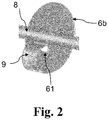
- each quartz glass pane 6a, 6b, 6c is connected to a tubular half-shell 9. This is in Figure 1 only hinted at and in Figure 2 better to see.
- One free leg of the pipe half-shell 9 ends at the transfer opening 61 and the other close to the edge of the quartz glass pane 6a, 6b, 6c.
- a rotary tube rotation in the arranged with reference to the direction of arrow 24 direction of rotation of the marginal leg immersed in the bed of SiO 2 granules 5 and shoveling upon further rotation of the thereby entrained SiO 2 granulate 5 to the transfer opening 61, from where the it in Transport direction 5a downstream chamber B, C, D arrives.
- the transfer openings 61 are designed with an oval cross section and run asymmetrically to the axis of rotation 21.
- a resistance heating device (not shown in the figure) is provided on the outer jacket of the rotary tube 8.
- the quartz glass panes 6a and 6c are located outside the heated length of the rotary tube 2; they are made of opaque quartz glass that reflects thermal radiation.
- the lower end of the gas guide tube 8 also consists of opaque quartz glass that reflects thermal radiation. It is led out of the rotary kiln 1 through a rotary feedthrough 29 and connected to a line for the supply of the treatment gas (indicated by the block arrow 11). The treatment gas 11 fed into the gas distributor pipe 8 flows in the opposite direction 11a to the grain transport direction 51 through the treatment space 7.
- a suction pipe 14 protrudes into the upper end of the gas distributor pipe 8.
- the block arrow 15 indicates the connection of the suction pipe 14 to a suction device.
- the suction pipe 14 does not rotate and has no or at most slight mechanical contact with the inner wall of the gas distributor pipe 8.
- the end of the suction pipe 14 protruding into the gas distributor pipe 8 ends at a position P2 in the treatment room B, at which the extracted and used treatment gas has a temperature, which is higher than the condensation temperature (T K ) of the impurities in the treatment gas.
- Amorphous SiO 2 granules 5 to be continuously cleaned are fed to the rotary tube 2 rotating at 8 rpm about its axis of rotation 21 at a feed rate of 8 kg / h.
- the rotary tube 2 is inclined in the longitudinal direction at the specific angle of repose of the SiO 2 grain 5 so that an approximately uniform thickness of the grain bed 5 is established over its length, which is continuously moved from the grain inlet 22 to the grain outlet 23.
- the rotary kiln 1 is heated to a maximum temperature of around 1200 ° C. in the region of the reaction chamber C by means of the resistance heating device.
- a reactive treatment gas 11 in the form of a gas mixture of HCl, chlorine and nitrogen with a volume flow of 200 l / h is introduced into the end of the gas distributor pipe 8 rotating about the axis of rotation 21 and protruding from the rotary kiln 1 via the rotary union 9.
Landscapes
- Engineering & Computer Science (AREA)
- Mechanical Engineering (AREA)
- General Engineering & Computer Science (AREA)
- Chemical & Material Sciences (AREA)
- Organic Chemistry (AREA)
- Chemical Kinetics & Catalysis (AREA)
- Materials Engineering (AREA)
- Life Sciences & Earth Sciences (AREA)
- General Chemical & Material Sciences (AREA)
- Geochemistry & Mineralogy (AREA)
- Environmental & Geological Engineering (AREA)
- Inorganic Chemistry (AREA)
- Thermal Sciences (AREA)
- Physics & Mathematics (AREA)
- Manufacturing & Machinery (AREA)
- General Life Sciences & Earth Sciences (AREA)
- Devices And Processes Conducted In The Presence Of Fluids And Solid Particles (AREA)
- Muffle Furnaces And Rotary Kilns (AREA)
- Silicon Compounds (AREA)
- Furnace Details (AREA)
Abstract
Description
- Die vorliegende Erfindung betrifft ein Verfahren zur Behandlung rieselfähiger anorganischer Körnung in einem beheizten, um eine Rotationsachse rotierenden Drehrohr, das einen Behandlungsraum umgibt, der mittels Trennelementen in mehrere Behandlungszonen, davon mindestens eine Reaktionszone, unterteilt ist, wobei die Körnung an einer Körnungseinlassseite dem Behandlungsraum zugeführt und in einer Körnungs-Transportrichtung zu einer Körnungsauslassseite transportiert und dabei einem Behandlungsgas ausgesetzt wird.
- Außerdem betrifft die Erfindung ein Drehrohr zur Behandlung rieselfähiger anorganischer Körnung, das um eine zur Horizontalen geneigte Rotationsachse rotierbar ist, und das einen Behandlungsraum zur Aufnahme der Körnung umgibt, der mittels Trennelementen in mehrere Behandlungszonen, davon mindestens eine Reaktionszone, unterteilt ist, und der eine Körnungseinlassseite zum Einführen der Körnung in den Behandlungsraum und eine Körnungsauslassseite zum Austragen der Körnung aus dem Behandlungsraum sowie einen Gaseinlass zum Einleiten eines Behandlungsgases in die Reaktionszone und einen Gasauslass zur Ausleitung von verbrauchtem Behandlungsgas aus dem Behandlungsraum ausweist.
- Derartige Behandlungsverfahren unter Einsatz eines Drehrohr-Ofens werden beispielsweise zum Reinigen amorpher oder kristalliner Körnung, insbesondere aus SiO2 eingesetzt.
- SiO2-Körnungen werden als Rohstoff für die Herstellung von Quarzglas eingesetzt. Bei vielen Anwendungen von Quarzglas, beispielsweise als Bauteil zum Einsatz bei der Halbleiterherstellung oder für die Optik, werden an die Reinheit hohe Anforderungen gestellt, die nur unter großem Zeit-, Material- und Kostenaufwand zu erreichen sind. Durch Behandlung unter chlorhaltiger Atmosphäre bei hoher Temperatur (Thermochlorierung) werden Verunreinigungen wie Eisen, Titan, Alkali- und Erdalkalimetallen entfernt. Ein derartiges Verfahren zur kontinuierlichen Reinigung von Quarzpulver durch Thermochlorierung in einem Drehrohrofen ist in der
US 5,637,284 A beschrieben. Das zu reinigende Quarzpulver wird kontinuierlich einer Einlassseite eines schräg gestellten und elektrisch beheizten Drehrohrs aus Quarzglas zugeführt und durchläuft darin nacheinander eine Vorheizkammer, eine Reaktionskammer und eine Gas-Desorptionskammer. Die jeweiligen Kammern sind mittels durchlässiger Trennelemente, die auch zur Durchmischung des Quarzpulvers dienen, voneinander separiert. In der Vorheizkammer wird das Quarzpulver auf etwa 800 °C erwärmt, bevor es in der Reaktionskammer bei einer Temperatur um 1300 °C mit einem Gasgemisch aus Chlor und Chlorwasserstoff behandelt wird. Dieses Gasgemisch wird mittels eines in der Drehrohr-Längsachse verlaufenden Gaslanze von der Auslassseite her in die Reaktionskammer eingeleitet. Das Gasgemisch reagiert mit Verunreinigungen des Quarzpulvers unter Bildung gasförmiger Metallchloride. In der Desorptionskammer werden das verbrauchte Gasgemisch und die gasförmigen Reaktionsprodukte abgesaugt. Dafür dient eine weitere Gaslanze, die von der Auslassseite aus in die Desorptionskammer hineinragt. - Die feststehende Lanze zum Zuführen des Behandlungsgases verformt sich bei hoher Temperatur von beispielsweise 1200°C. Dadurch tritt das Behandlungsgas an wechselnden Stellen mit der SiO2-Körnung in Kontakt, wodurch die Reproduzierbarkeit der Reinigungsergebnisse leidet. Infolge der stirnseitig offenen Enden und der großen Querschnittsfläche des Drehrohres strahlt der Ofen viel Wärme an den Stirnseiten ab. Der Einsatz von dichten Drehdurchführungen am heißen Ende des Drehrohres ist aufgrund der hohen Temperatur nicht möglich.
- Bei dem aus der
WO 2010/037473 A1 bekannten kontinuierlichen Reinigungsverfahren für SiO2-Körnung in einem Drehrohrofen sind im Drehrohr-Innenraum Einbauten wie Schaufeln oder Noppen montiert, die zum Transport und zur Durchmischung der zu reinigenden Körnung dienen. - Die
US 7,837,955 B2 beschreibt ein kontinuierliches Reinigungsverfahren für Quarzsand in einem Drehrohrofen, bei dem im Drehrohr vertikale Trennplatten eingelassen sind, wobei der Quarzsand zwischen dem äußeren Rand der Trennwand und der Drehrohr-Innenwandung hindurch geleitet wird. Der Quarzsand wird dabei vom dem einen Ende und das Behandlungsgas wird vom anderen Ende in das Drehrohr eingeführt. Der Innendruck innerhalb des Drehrohres kann höher sein als der außen anliegende Druck (Atmosphärendruck). - Die
WO 88/03914 A1 - Die
DE 10 2010 021 693 A1 beschreibt ein kontinuierliches Verglasen eines porösen SiO2-Granulats zu einer transparenten, synthetischen Quarzglaskörnung. Dabei wird eine Schüttung des Granulats in einem Drehrohrofen mit einem um seine Mittelachse rotierenden Drehrohr und mit einer Innenwandung aus Quarzglas von einem Laserstrahl erhitzt. Durch Erzeugen einer Relativbewegung zwischen Schüttung und Laserstrahl wird ein gleichmäßiges Verglasen der Granulatteilchen ohne Agglomerierung erzielt. - Der Grad der Einwirkung des Behandlungsgases auf die Körnung in einem Drehrohrofen hängt von der Einwirkungsdauer und der Temperatur ab. Insbesondere hängt beispielsweise der Reinigungseffekt der Thermochlorierung von der Reaktionsdauer der SiO2-Körnung mit dem chlorhaltigen Gasgemisch und von der Reaktionstemperatur ab.
- Bei höheren Temperaturen reagiert Chlor schneller mit den metallischen Verunreinigungen ab, so dass mit steigender Temperatur ein besserer Reinigungseffekt zu erwarten wäre. Allerdings ist die Möglichkeit der Temperaturerhöhung aus mehreren Gründen limitiert, unter anderem deswegen, da sich bei hohen Temperaturen aufgrund des Erweichens der SiO2-Körnung Agglomerate bilden, die den weiteren Zutritt des Behandlungsgases zur Oberfläche der einzelnen Körner erschweren. Der Reinigungseffekt durch das Behandlungsgas, das in erster Linie an der Oberfläche der Körnung wirkt, wird dadurch verringert.
- Die mittlere Verweilzeit eines Partikels ist abhängig von der Füllmenge des Drehrohrs: je höher die Füllmenge, desto länger die Kontaktzeit mit dem Reaktivgas und desto besser damit das Reinigungsergebnis. Umgekehrt, ermöglicht eine vergleichsweise größere Füllmenge bei gleicher Verweilzeit einen höheren Durchsatz. Eine längere Verweilzeit kann auch durch verringerte Drehzahl des Rohrs erreicht werden. Damit wird aber auch die Umwälzung des Inhalts vermindert und somit der Kontakt mit dem Reaktionsgas.
- Durch einen hohen Falschluftanteil im Behandlungsgas können unkontrollierte und unerwünschte Nebenreaktionen stattfinden. Durch undefinierte und uneffektive Strömungspfade bleibt ein Großteil des Behandlungsgases ungenutzt und muss durch Neutralisation aufwändig entsorgt werden.
- Gelöste Verunreinigungen kondensieren an kalten Bereichen des Drehrohrs und lagern sich mit der Zeit als Feststoff ab. Fallen die Ablagerungen in die zu behandelnde SiO2-Körnung, erzeugen sie Fehler oder Ausschuss in nachfolgenden Weiterverarbeitungsprozessen, wie etwa beim Einschmelzen der Körnung zur Herstellung von Quarzglas.
- Der Erfindung liegt daher die Aufgabe zugrunde, ein Verfahren anzugeben, das eine thermische Behandlung anorganischer rieselfähiger Körnung, insbesondere von SiO2-Körnung im Drehrohrofen, insbesondere die Aufreinigung durch Thermochlorierung, bei geringem und effektivem Verbrauch von Behandlungsgas zuverlässig und reproduzierbar ermöglicht.
- Weiterhin liegt der Erfindung die Aufgabe zugrunde, ein zur Durchführung des Verfahrens geeignetes, möglichst zuverlässiges Drehrohr zum Einsatz in einem Drehrohrofen bereitzustellen.
- Hinsichtlich des Verfahrens wird diese Aufgabe ausgehend von einem Verfahren der eingangs genannten Gattung erfindungsgemäß dadurch gelöst, dass verbrauchtes Behandlungsgas aus der Reaktionszone mittels eines um seine Längsachse rotierenden Gasverteilerrohres abgesaugt wird.
- Der von der Drehrohr-Innenbohrung definierte Behandlungsraum ist mit Hilfe von Trennelementen, wie beispielsweise mittels Quarzglasscheiben, in mehrere Zonen (auch als "Kammern" bezeichnet) unterteilt. Die Zonen sind für unterschiedliche Funktionen ausgelegt, wie etwa zum Vorheizen oder Abkühlen der Körnung vor beziehungsweise nach einer eigentlichen Hochtemperatur-Behandlung, die überwiegend in der Reaktionszone stattfindet.
- Bei der thermischen Behandlung ist eine möglichst gleichmäßige Einwirkung des Behandlungsgases auf die Körnung erwünscht. Die Behandlung dient beispielsweise zum Reinigen der anorganischen Körnung, insbesondere von SiO2-Körnung, wobei in dem Fall das Behandlungsgas halogenhaltige Substanzen enthalten kann.
- Das erfindungsgemäße Verfahren zielt darauf ab, dass Abgas, also verbrauchtes, verunreinigtes Behandlungsgas, möglichst wenig mit der zu behandelnden Körnung in Kontakt kommt. Dazu wird verbrauchtes Behandlungsgas aus der Reaktionszone mittels eines um sine Rohr-Längsachse rotierenden Gasverteilerrohres abgesaugt, das an einem "Absaug-Ende" des Drehrohrs endet. Dadurch ergeben sich mehrere Vorteile:
- Das im Gasverteilerrohr geführte und verbrauchte Behandlungsgas ist von der Körnung separiert. Insoweit schafft das Gasverteilerrohr für das verbrauchte Behandlungsgas einen von der zu behandelnden Körnung getrennten Materialtransportpfad.
- Der im Vergleich zum Drehrohr-Innendurchmesser kleinere Querschnitt des Gasverteilerrohres ermöglicht ein effektives Absaugen von mindestens einem Teil des verbrauchten Behandlungsgases aus der Reaktionszone.
- Durch effektives Entfernen von verbrauchtem und mit Verunreinigungen beladenem Behandlungsgas aus dem Behandlungsraum werden Kondensationen an kalten Stellen im Behandlungsraum und Ablagerungen und die damit einhergehenden Störungen und Verunreinigungen der Körnung unterdrückt.
- Die Rotationsachse des Drehrohres und die Rohr-Längsachse des Gasverteilerrohres verlaufen im einfachsten und bevorzugten Fall koaxial. Dadurch, dass das Gasverteilerrohr - vorzugsweise in der Rotationsachse des Drehrohres - rotiert, wird eine Verformung aufgrund hoher Temperatur vermieden. Die Effektivität der Absaugung von verbrauchtem Behandlungsgas aus der Reaktionszone ist daher reproduzierbar und beispielsweise zeitlich weitgehend konstant.
- Verbrauchtes Behandlungsgas wird vorteilhafterweise aus dem Gasverteilerrohr mittels eines rotatorisch feststehenden Absaugrohres abgesaugt.
- Das Absaugrohr ist mit dem Gasverteilerrohr nicht verbunden. Es ragt beispielsweise in das Gasverteilerrohr hinein oder es schließt möglichst dicht aber kontaktlos an das Gasverteilerrohr an. Das Abgas des Drehrohrofens kann sehr heiß sein, was die Realisierung einer dichten Drehdurchführung für die Ausleitung des heißen Behandlungsgases an dieser Stelle erschwert. Dadurch, dass das Absaugrohr mit dem rotierenden Gasverteilerrohr keine feste mechanische Verbindung hat, kann ein feststehendes Absaugrohr eingesetzt und daher auf eine Drehdurchführung verzichtet werden. Das Absaugrohr steht am Ende des Materialtransportpfades für das Behandlungsgas. Es kann zusätzlich gekühlt werden, indem Fremdluft von außerhalb des Gasverteilerrohres zusätzlich eingesaugt wird. Das abgesaugte Behandlungsgas und die dabei abgesaugte Fremdluft kommen nicht mehr mit der zu behandelnden Körnung in Kontakt.
- Bei einer besonders bevorzugten Verfahrensweise wird ein Absaugrohr eingesetzt, das in das Gasverteilerrohr hineinragt.
- In Richtung auf das "Absaug-Ende" nehmen die Temperaturen innerhalb des Drehrohrs und des Behandlungsgases ab. Das in das Gasverteilerrohr hineinragende Ende des Absaugrohres kann an eine Position innerhalb des Drehrohrs verschoben werden, bei der noch eine Temperatur oberhalb der Kondensationstemperatur herrscht. Da die Temperatur an der effektiven Absaugposition höher ist als die Kondensationstemperatur findet beim Abkühlen des verbrauchten Behandlungsgases Kondensation innerhalb des Absaugrohres statt. Die sich dort bildenden Ablagerungen können nicht in die Körnung gelangen. Das Absaugrohr wird infolge der Ablagerungen von Zeit zu Zeit ausgetauscht.
- Das Behandlungsgas wird vorzugsweise an der Körnungsauslassseite in das Gasverteilerrohr eingeleitet und entgegen der Körnungs-Transportrichtung von einer Kammer zur nächsten Kammer geleitet, wobei es durch mindestens eine Gasauslassöffnung aus dem Gasverteilerrohr in die Reaktionszone austritt, und verbrauchtes Behandlungsgas durch mindestens eine Gaseinlassöffnung aus der Reaktionszone in das Gasverteilerrohr wieder eintritt.
- Durch die Einleitung des Behandlungsgases in den Behandlungsraum im Gegenstrom zur Transportrichtung der Körnung wird gewährleistet, dass die weitgehend fertig behandelte, beispielsweise weitgehend gereinigte SiO2-Körnung, nur mit frischem, wenig belastetem Behandlungsgas in Kontakt kommt.
- Das Gasverteilerrohr erlaubt eine definierte und zielgenaue Einleitung des Behandlungsgases mit vergleichsweise wenig Falschluft in die Reaktionszone. Undefinierte und uneffektive Strömungspfade werden weitgehend vermieden. Die mit der Falschlufteinleitung eingetragenen und durch Reaktion erzeugten Verunreinigungen werden verringert. Die effektive Nutzung des Behandlungsgases verringert die Material- und Entsorgungskosten.
- Durch die Rotation des Gasverteilerrohres um seine Längsachse, vorzugsweise um die Drehrohr-Rotationsachse, wird eine Verformung auch im Bereich der Einleitung des Behandlungsgases in den Behandlungsraum vermieden, so dass sich die Position der Gaseinleitung in die Reaktionszone und der Einwirkung des Behandlungsgases auf die Körnung zeitlich konstant ist und eine reproduzierbare Wechselwirkung zwischen dem Behandlungsgas und der Körnung gewährleistet ist.
- Die mindestens eine Gasauslassöffnung befindet sich dabei - in Strömungsrichtung des Behandlungsgases gesehen - möglichst am Anfang der Reaktionszone, und die mindestens eine Gaseinlassöffnung befindet sich möglichst am Ende der Reaktionszone.
- Die Gasauslassöffnung kann als vordere Wandungsöffnung des Gasverteilerrohres, und die Gaseinlassöffnung kann als hintere Wandungsöffnung des Gasverteilerrohres ausgeführt sein, wobei in dem Fall das Gasverteilerrohr über seine Länge zwischen der vorderen und der hinteren Wandungsöffnung mindestens teilweise, vorzugsweise vollständig verschlossen ist. In diesem Fall kann ein Gasverteilerrohr eingesetzt werden, das sich durch den gesamten Behandlungsraum erstreckt und dessen Längsachse koaxial zur Drehrohr-Rotationsachse verläuft.
- Im Hinblick auf eine möglichst effektive erzwungene Durchströmung der anorganischen Körnung mit frischen Behandlungsgas in der Reaktionszone ist es vor-teilhaft, wenn die vordere Wandungsöffnung und die hintere Wandungsöffnung auf unterschiedlichen Umfangswinkeln der Gasverteilerrohr-Mantelfläche liegen, vorzugsweise auf entgegengesetzten Umfangseiten
- Ein möglichst vollständiger Austritt des Behandlungsgases aus dem Gasverteilerrohr kann aber auch gewährleistet werden, wenn das Gasverteilerrohr aus getrennten Rohrstücken zusammengesetzt ist, wobei das - in Strömungsrichtung des Behandlungsgases gesehen - vordere Rohrstück am vorderen Trennelement endet oder sich allenfalls von dort ein kurzes Stück in die Reaktionszone erstreckt, und das hintere Rohrstück am hinteren Trennelement endet oder sich allenfalls von dort ein kurzes Stück in die Reaktionszone erstreckt. In dem Fall sind die Gasauslass- und Gaseinlassöffnungen grundsätzlich auch als stirnseitige Rohröffnungen ausführbar, vorzugsweise sind es aber Öffnungen in der Rohrwandung des Rohrstücks, um ein Umleiten des Behandlungsgases aus der zentralen Achse der Reaktionskammer in Richtung auf die Körnung zu erzwingen.
- Das Behandlungsgas wird über die Gaseinlassöffnung aus dem Gasverteilerrohr in die Reaktionskammer eingeleitet, und über die Gaseinlassöffnung wird mindestens ein Teil des Behandlungsgases wieder in das Gasverteilerrohr eingesaugt und im Gasverteilerrohr weitergeleitet. Dazu trägt auch ein Druckgradient mit einem niedrigeren Druck in der Gasphase der Drehrohr-Innenbohrung am Absaug-Ende des Drehrohres bei. Der Druckgradient stellt sich entweder infolge der einseitigen Absaugung des verbrauchten Behandlungsgases am "Absaug-Ende"
oder infolge einer beidseitigen Absaugung am Drehrohr aber mit höherer Saugleistung am "Absaug-Ende" automatisch ein, und er bewirkt einen Transport des Behandlungsgases und von verbrauchtem Behandlungsgas in Richtung auf das Absaug-Ende des Drehrohrs. - Vorzugsweise ist das Gasverteilerrohr mit mindestens einem Trennelement drehfest verbunden, und die Trennelemente weisen zum Durchlass von Körnung von einer Zone zur nächsten Zone jeweils eine Übergabeöffnung auf.
- Die Trennelemente sind mit dem Drehrohr fest verbunden und drehen sich mit diesem. Dadurch, dass das Gasverteilerrohr mit mindestens einem der Trennelemente, vorzugsweise mit allen Trennelementen, fest verbunden ist, dreht es sich synchron mit dem Drehrohr, ohne dass dafür ein separater Antrieb benötigt wird. Die Übergabeöffnungen bilden Durchgänge zwischen jeweils zwei benachbarten Behandlungszonen und stellen einen durchgehenden Transportpfad für die Körnung sicher. Jedes Trennelement kann über eine Übergabeöffnung oder über mehrere Übergabeöffnungen verfügen. Für die Position der Übergabeöffnung am Trennelement beziehungsweise für die Positionen und die Verteilung mehrerer Übergabeöffnungen am Trennelement gibt es keine Festlegung..
- Die Trennelemente sind dabei vorzugsweise mit mindestens einem Körnungs-Mitnehmer ausgestattet, der infolge der Drehrohr-Rotation in die Körnung eintaucht und dabei mitgenommene Körnung zur Übergabeöffnung verfrachtet.
- Der Körnungs-Mitnehmer befindet sich auf derjenigen Seite des Trennelements, die der fließenden Körnung zugewandt ist. Infolge der Drehrohr-Rotation schaufelt der Körnungs-Mitnehmer die Körnung durch die Übergabeöffnung von der einen Behandlungszone in die benachbarte Behandlungszone. Er ist beispielsweise als Rohrhalbschale oder Rutsche ausgebildet, die an der Übergabeöffnung endet.
- Die mit die mit derartigen Körnungs-Mitnehmern ausgestatteten Trennelemente dienen nicht nur zur Unterteilung des Behandlungsraums in mehrere Zonen, sondern die bewirken oder erleichtern infolge der Rotation des Drehrohrs um seine Rotationsachse außerdem den Transport der Körnung von der einen Behandlungszone in die nächste Behandlungszone.
- Bei einer bevorzugten Ausführungsform des erfindungsgemäßen Verfahrens dienen die mit derartigen Körnungs-Mitnehmern ausgestatteten Trennelemente auch zur Steuerung des Körnungs-Durchsatzes. Denn bei einer gegenläufigen Rotation des Drehrohres wirken die Körnungs-Mitnehmer nicht als Schaufel für die SiO2-Körnung, sondern im Gegenteil, sie schieben die Körnung von der Übergabeöffnung weg, so dass der weitere Körnungstransport angehalten werden kann.
- In Körnungs-Transportrichtung gesehen ist der Körnungseinlassseite ein vorderes Trennelement nachgeordnet und der Körnungsauslassseite ein hinteres Trennelement vorgeordnet, wobei es sich als vorteilhaft erweisen hat, wenn das vordere und/oder das hintere Trennelement aus opakem Quarzglas ausgeführt sind.
- Das opake Quarzglas reflektiert Wärmestrahlung aus dem Behandlungsraum und schirmt die Körnungseinlass- und/oder -auslassseite dadurch vor der Hitze der Reaktionszone ab. Das hintere Trennelements aus opakem Quarzglas schirmt beispielsweise die Körnungsauslassseite (gleichbedeutend mit der Einleitungsseite für das Behandlungsgas) vor Wärme ab und ermöglicht dadurch eine Drehdurchführung für das rotierende Gasverteilerrohr in den Behandlungsraum.
- Im Hinblick auf eine effektive Wärmeabschirmung hat eine Verfahrensvariante Vorteile, bei der das Drehrohr nicht beheizte stirnseitige Endabschnitte aufweist, wobei das vordere und das hintere Trennelement jeweils in einem nicht beheizten stirnseitigen Endabschnitt angeordnet sind.
- In dem Zusammenhang hat es sich außerdem als vorteilhaft erwiesen, wenn das Gasverteilerrohr einen an der Körnungsauslassseite aus dem Drehrohr herausragenden Längenabschnitt aufweist, und dass mindestens dieser Längenabschnitt aus opakem Quarzglas ausgeführt ist.
- Der Längenabschnitt aus opakem Quarzglas reflektiert Wärmestrahlung und vermindert die Leitung in der Wandung des Gasverteilerrohres zum stirnseitigen Ende an der Körnungsauslassseite. Dies trägt dazu bei, dass das rotierende Gasverteilerrohr in den Behandlungsraum über eine Drehdurchführung geführt und dadurch das Behandlungsgas ohne jede Fremdluft in den Behandlungsraum eingeführt werden kann.
- Hinsichtlich des Drehrohrs wird die oben angegebene Aufgabe ausgehend von einem Drehrohr der eingangs genannten Gattung erfindungsgemäß dadurch gelöst, dass der Gasauslass ein um seine Längsachse rotierendes Gasverteilerrohr umfasst.
- Der von der Drehrohr-Innenbohrung definierte Behandlungsraum ist mit Hilfe von Trennelementen, wie beispielsweise mittels Quarzglasscheiben, in mehrere Zonen (auch als "Kammern" bezeichnet) unterteilt. Die Zonen sind für unterschiedliche Funktionen ausgelegt, wie etwa zum Vorheizen oder Abkühlen der Körnung vor beziehungsweise nach einer eigentlichen Hochtemperatur-Behandlung, die überwiegend in der Reaktionszone stattfindet.
- Um verbrauchtes Behandlungsgas aus der Reaktionszone abzusaugen, verfügt das erfindungsgemäße Drehrohr über ein um seine Rohr-Längsachse rotierbares Gasverteilerrohr, das an einem "Absaug-Ende" des Drehrohrs endet. Dadurch ergeben sich mehrere Vorteile:
- Das im Gasverteilerrohr geführte und verbrauchte Behandlungsgas ist von der Körnung separiert. Insoweit schafft das Gasverteilerrohr für das verbrauchte Behandlungsgas einen von der zu behandelnden Körnung getrennten Materialpfad.
- Der im Vergleich zum Drehrohr-Innendurchmesser kleinere Querschnitt des Gasverteilerrohres ermöglicht ein effektives Absaugen von mindestens einem Teil des verbrauchten Behandlungsgases aus der Reaktionszone.
- Durch effektives Entfernen von verbrauchtem und mit Verunreinigungen beladenem Behandlungsgas aus dem Behandlungsraum werden Kondensationen an kalten Stellen im Behandlungsraum und Ablagerungen und die damit einhergehenden Störungen und Verunreinigungen der Körnung unterdrückt.
- Die Rotationsachse des Drehrohres und die Rohr-Längsachse des Gasverteilerrohres verlaufen im einfachsten und bevorzugten Fall koaxial. Dadurch, dass das Gasverteilerrohr vorzugsweise in der Rotationsachse des Drehrohres rotiert werden kann, kann eine Verformung aufgrund hoher Temperatur vermieden werden. Die Effektivität der Absaugung von verbrauchtem Behandlungsgas aus der Reaktionszone ist daher reproduzierbar und beispielsweise zeitlich weitgehend konstant.
- Der Gasauslass umfasst vorteilhafterweise ein Absaugrohr, das kontaktlos in das Gasverteilerrohr hineinragt oder ohne direkten Kontakt an das Gasverteilerrohr anschließt. Das Absaugrohr dient zur Absaugung von verbrauchtem Behandlungsgas aus dem Gasverteilerrohr.
- Das Absaugrohr ist mit dem Gasverteilerrohr nicht fest verbunden; es ragt beispielsweise in das Gasverteilerrohr hinein oder es schließt möglichst dicht aber kontaktlos an das Gasverteilerrohr an. Dadurch, dass das Absaugrohr mit dem um die Rohr-Längsachse rotierenden Gasverteilerrohr keinen mechanischen Kontakt hat, kann ein rotatorisch feststehendes Absaugrohr eingesetzt und daher auf eine Drehdurchführung verzichtet werden.
- Die nachfolgend genannten vorteilhaften Ausführungsformen des erfindungsgemäßen Drehrohres entsprechen Maßnahmen des erfindungsgemäßen Verfahrens. Dazu wird auf die obigen Erläuterungen zu den jeweiligen Verfahrensmaßnahmen verwiesen.
- Vorzugsweise ist der Gaseinlass an einem Gaseinlassende des Gasverteilerrohres vorgesehen, der am Körnungsauslassende des Drehrohres liegt.
- Vorteilhafterweise weist das Gasverteilerrohr mindestens eine Gasauslassöffnung zur Ausleitung von Behandlungsgas aus dem Gasverteilerrohr in die Reaktionszone und mindestens eine Gaseinlassöffnung zur Einleitung von Behandlungsgas aus der Reaktionszone in das Gasverteilerrohr auf, wobei die Gasverteilerrohr-Innenbohrung vorzugsweise zwischen der Gasauslassöffnung und der Gaseinlassöffnung mindestens teilweise verschlossen ist.
- Es hat sich bewährt, wenn das Gasverteilerrohr mit mindestens einem Trennelement drehfest verbunden ist, wobei die Trennelemente zum Durchlass von Körnung jeweils eine Übergabeöffnung aufweisen, durch die hindurch sich das Gasverteilerrohr erstreckt, und dass die Trennelemente mit einem Körnungs-Mitnehmer ausgestattet sind, der dazu ausgelegt ist, infolge der Drehrohr-Rotation in die Körnung einzutauchen und dabei mitgenommene Körnung zur Übergabeöffnung zu verfrachten.
- Weiterhin hat es sich bewährt, wenn in Körnungs-Transportrichtung gesehen der Körnungseinlassseite ein vorderes Trennelement nachgeordnet ist und der Körnungsauslassseite ein hinteres Trennelement vorgeordnet ist, wobei das vordere und/oder das hintere Trennelement aus opakem Quarzglas ausgeführt sind.
- In dem Zusammenhang hat es sich auch als günstig erwiesen, wenn das Drehrohr nicht beheizte stirnseitige Endabschnitte aufweist, wobei das vordere und das hintere Trennelement jeweils in einem nicht beheizten stirnseitigen Endabschnitt angeordnet sind.
- Bei einer bevorzugten Ausführungsform des Drehrohrs weist das Gasverteilerrohr einen am Körnungsauslass aus dem Drehrohr herausragenden Längenabschnitt auf, wobei mindestens dieser Längenabschnitt aus opakem Quarzglas ausgeführt ist.
- Nachfolgend wird die Erfindung anhand eines Ausführungsbeispiels und einer Zeichnung näher erläutert. Im Einzelnen zeigt in schematischer Darstellung
- Figur 1
- einen Drehrohrofen mit einem von einem Drehrohr aus Quarzglas gemäß der Erfindung gebildeten Behandlungsraum in einer dreidimensionalen Ansicht, und
- Figur 2
- ein Trennelement zum Aufteilen des Behandlungsraums in einer gegenüber
Figur 1 vergrößerten Darstellung. - Der in
Figur 1 schematisch dargestellte Drehrohrofen 1 umfasst ein Drehrohr 2 aus Quarzglas, das um eine zur Horizontalen 3 leicht schräg verlaufende Rotationsachse 21 (Neigungswinkel etwa 4 Grad) rotierbar ist. Dem oberen Drehrohr-Ende 22 (Körnungseinlassseite) wird über eine mit einem Blockpfeil 4 angedeutete Einfüllvorrichtung eine im Drehrohrofen 1 zu behandelnde SiO2-Körnung 5 zugeführt. Der Richtungspfeil 51 zeigt die Bewegungsrichtung der SiO2-Körnung 5 im Laufe der Behandlung bis zum unteren Drehrohrende 23, das über Rollenlager 25 aus dem Gehäuse des Drehrohrofens 1 herausgeführt ist, und in eine Materialentnahmevorrichtung 13 für die behandelte SiO2-Körnung mündet. - Die Innenbohrung des Drehrohres 2 bildet einen Behandlungsraum 7, der mittels Quarzglasscheiben 6a, 6b, 6c in vier Kammern unterteilt ist, nämlich in eine Materialeinlaufkammer A, eine Vorheizkammer B, eine Reaktionskammer C, und in eine Abkühl- oder Desorptionskammer D. Die Quarzglasscheiben 6a, 6b, 6c sind an der Innenwand des Drehrohres 2 angeschweißt und haben jeweils eine zur Drehrohr-Längsachse konzentrische Durchgangsbohrung, durch die ein Gasführungsrohr 8 aus Quarzglas geführt ist.
- Das Gasführungsrohr 8 dient der Zufuhr von frischem Behandlungsgas in den Behandlungsraum 7 und der Ausleitung von verbrauchtem Behandlungsgas (Abgas) aus dem Behandlungsraum 7. Es erstreckt sich durch alle Kammern A-D des Behandlungsraums 7. Im Behandlungsraum 7 ist die Wandung des Gasführungsrohres 8 ist mit mehreren Wandungsöffnungen versehen, unterteilt in eine Gasauslassöffnung 82, durch die das Behandlungsgas 11 dem Gasverteilerrohr 8 in die Kammer C austritt, und eine Gaseinlassöffnung 83, über die verbrauchtes Behandlungsgas aus der Behandlungskammer C in das Gasverteilerrohr 8 wieder eintritt. Zwischen der Gasauslassöffnung 82 und der Gaseinlassöffnung 83 ist das Gasverteilerrohr 8 verschlossen (Verschluss 81) Zur Verbesserung der Durchströmung der SiO2-Körnung 5 mit frischen Behandlungsgas in der Behandlungskammer C befinden sind die Gasauslassöffnung 82 und die Gaseinlassöffnung 83 (anders als in der
Figur 1 schematisch gezeigt) auf entgegengesetzten Umfangseiten des Gasführungsrohres 8. - Das Gasverteilerrohr 8 ist mit den Quarzglasscheiben 6 verbunden und wie diese um die Rotationsachse (Drehrohr-Längsachse 21) rotierbar. Die Gasverteilerrohr-Längsachse, die Drehrohr-Längsachse 21 und die Rotationsachse verlaufen koaxial.
- Auf ihrer der anfließenden SiO2-Körnung 5 zugewandten Seite ist jede Quarzglasscheibe 6a, 6b, 6c mit einer Rohrhalbschale 9 verbunden. Diese ist in
Figur 1 nur angedeutet und inFigur 2 besser zu erkennen. Ein freier Schenkel der Rohrhalbschale 9 endet an der Übergabeöffnung 61 und der andere nahe am Rand der Quarzglasscheibe 6a, 6b, 6c. Bei einer Drehrohr-Rotation in der anhand des Richtungspfeils 24 angeordneten Drehrichtung taucht der randständige Schenkel in die Schüttung der SiO2-Körnung 5 ein und schaufelt bei weiterer Drehung die dabei mitgenommene SiO2-Körnung 5 zur Übergabeöffnung 61, von wo sie in die in Transportrichtung 5a nachgeordnete Kammer B, C, D gelangt. Die Übergabeöffnungen 61 sind zu dem Zweck mit ovalem Querschnitt ausgeführt und verlaufen asymmetrisch zur Rotationsachse 21. - Am Außenmantel des Drehrohres 8 ist eine (in der Figur nicht dargestellte) Widerstandsheizeinrichtung vorgesehen. Die Quarzglasscheiben 6a und 6c befinden sich außerhalb des beheizten Längenabschnitts des Drehrohres 2; sie bestehen aus opakem, Wärmestrahlung reflektierendem Quarzglas.
- Das untere Ende des Gasführungsrohres 8 besteht ebenfalls aus opakem, Wärmestrahlung reflektierendem Quarzglas. Es ist durch eine Drehdurchführung 29 aus dem Drehrohrofen 1 herausgeführt und an eine Leitung für die Zufuhr des Behandlungsgases angeschlossen (angezeigt durch den Blockpfeil 11). Das in das Gasverteilerrohr 8 eingespeiste Behandlungsgas 11 strömt in Gegenrichtung 11a zur Körnungs-Transportrichtung 51 durch den Behandlungsraum 7.
- An seinem oberen Ende wird verbrauchtes Behandlungsgas aus dem Gasverteilerrohr 8 abgesaugt. Zu diesem Zwecke ragt ein Absaugrohr 14 in das obere Ende des Gasverteilerrohres 8 hinein. Der Blockpfeil 15 zeigt den Anschluss des Absaugrohres 14 an eine Absaugung an. Das Absaugrohr 14 rotiert nicht und hat keinen oder allenfalls leichten mechanischen Kontakt mit der Innenwandung des Gasverteilerrohres 8. Das in das Gasverteilerrohr 8 hineinragende Ende des Absaugrohres 14 endet an einer Position P2 im Behandlungsraum B, an der das abgesaugte und verbrauchte Behandlungsgas eine Temperatur hat, die höher ist als die Kondensationstemperatur (TK) der Verunreinigungen im Behandlungsgas.
- Die Herstellung des Drehrohres 2 mitsamt den Einbauten umfasst die folgenden Verfahrensschritte:
- Bereitstellen eines Drehrohres 2 aus Quarzglas mit einer Länge von 2500 mm und einem Innendurchmesser von 210 mm.
- Bereitstellung lasergeschnittenen kreisrunden Scheiben 6a und 6c aus opakem Quarzglas mit einer Scheibendicke von 5 mm und einem Außendurchmesser von 208 mm. Diese Scheiben 6a, 6c haben jeweils zwei Öffnungen: eine kreisrunde konzentrische Durchgangsbohrung zur Durchleitung des Gasverteilerrohres 8 und eine ovale außermittig angeordneten Übergabeöffnung 61 für die SiO2-Körnung. Bereitstellung einer lasergeschnittenen kreisrunden Scheibe 6b aus transparentem Quarzglas mit denselben Abmessungen wie die Scheiben 6a, 6c.
- Bereitstellen eines Gasverteilerrohres 8 aus transparentem Quarzglas mit einem Außendurchmesser von 40 mm und einem Innendurchmesser von 32 mm. Stirnseitiges Anschweißen eines Rohrendstücks aus opakem Quarzglas mit einer Länge von 50 mm unter Bildung des Gasverteilerrohres 8 mit einer Gesamtlänge von 2700 mm.
- Herstellung der Schaufeln 9 durch Segmentierung von Quarzglasrohren und Anschweißen der Schaufeln 9 an die Quarzglasscheiben 6a, 6b, 6c.
- Laserschneiden von Gaseinlass- und Gasauslassöffnungen (82; 83) in die Wandung des Gasverteilerrohres 8 und Anbringen eines Pfropfens 83 zum Verschließen der Gasverteilerrohr-Innenbohrung zwischen den Gaseinlass- und Gasauslassöffnungen (82; 83).
- Anschweißen der Quarzglasscheiben 6a, 6b, 6c in der Innenbohrung des Gasverteilerrohres 8 auf einer Glasdrehbank.
- Verbinden des Gasverteilerrohres 8 mit den Durchgangsbohrungen der Quarzglasscheiben 6a, 6b, 6c und Einsetzen dieses Verbundes in die Innenbohrung des Drehrohrs 2 und Verschweißen der Quarzglasscheiben mit der Drehrohr-Innenwandung durch lokales Erhitzen unter Verringerung des Durchmessers der Drehrohr-Innenbohrung auf der Glasdrehbank.
- Im Folgenden wird ein Ausführungsbeispiel für das erfindungsgemäße Behandlungsverfahren anhand der in den
Figuren 1 und2 schematisch dargestellten Vorrichtung näher beschrieben: Dem um seine Rotationsachse 21 mit 8 U/min rotierenden Drehrohr 2 wird mit einer Zufuhrrate von 8 kg/h kontinuierlich zu reinigende amorphe SiO2-Körnung 5 zugeführt. Das Drehrohr 2 ist in Längsrichtung im spezifischen Schüttwinkel der SiO2-Körnung 5 geneigt, so sich über seine Länge eine etwa gleichmäßige Dicke der Körnung-Schüttung 5 einstellt, die kontinuierlich vom Körnungseinlass 22 zum Körnungsauslass 23 bewegt wird. - Mittels der Widerstandsheizeinrichtung wird der Drehrohrofen 1 im Bereich der Reaktionskammer C auf eine Maximaltemperatur um 1200 °C erhitzt. In das um die Rotationsachse 21 rotierende und über die Drehdurchführung 9 aus dem Drehrohrofen 1 herausragende Ende des Gasverteilerrohres 8 wird ein reaktives Behandlungsgas 11 in Form eines Gasgemischs aus HCl, Chlor und Stickstoff mit einem Volumenstrom von 200l/h eingeleitet.
- Das im Gegenstrom zur SiO2-Körnung strömende Behandlungsgas 11 erwärmt sich schnell, verteilt sich insbesondere in die Behandlungszonen C und B und wird am oberen Ende als verbrauchtes Behandlungsgas 11 aus dem Gasverteilerrohr 8 mittels des Absaugrohres 14 abgesaugt.
-
Figur 1 zeigt oberhalb des Drehrohrofens 1 ein Diagramm mit einem typischen Temperatur (T)- und Druckverlauf (p) des Behandlungsgases 11. Die Position P2 repräsentiert die Stelle, an der das heiße Abgas (verbrauchtes Behandlungsgas) mittels des Absaugrohres 14 aus dem Gasverteilerrohr 8 entfernt wird. Hier findet eine Vermischung von heißem Abgas und Fremdluft statt, die über das Absaugrohr 14 von außen durch das Gasführungsrohr 8 eingesaugt wird. Dadurch ergibt sich ein Sprung sowohl im Temperaturverlauf (T) als auch im Druckverlauf (p) für das Behandlungsgas. Die Position P1 zeigt den Anfang der Vorwärmkammer B und die Position der vorderen Quarzglasscheibe 6a aus reflektierendem Quarzglas an. Die Position P3 entspricht dem Anfang der Reaktionskammer C und die Position P4 dem Ende der der Reaktionskammer C und der Position der hinteren Quarzglasscheibe 6c aus reflektierendem Quarzglas an. Die Position P5 entspricht dem Körnungsauslass. Es ist erkennbar, dass in der Gasphase über die gesamte Länge des Drehrohres 8 ein Druckgradient anliegt, der einen Gastransport zur Absaug-Position P2 bewirkt. An der Position Prel=0 hat das Behandlungsgas einen Gasdruck der dem außen anliegenden Druck (Atmosphärendruck) entspricht. - Die Einleitung des Behandlungsgases über das per Drehdurchführung 29 abgedichtete, rotierende Gasführungsrohr 8 bewirkt eine geringe Fremdluftzufuhr in den Behandlungsraum 7 und trägt zu einer höheren Konzentration des reaktiven Behandlungsgases 11 in der heißen Zone bei. Hierdurch ergibt sich ein besseres Reinigungsergebnis, bei gleichzeitiger Einsparung von reaktivem Behandlungsgas und geringerer Entsorgungskosten.
- Durch die Absaugung des noch heißen Behandlungsgases 11 in der Position P2 hat dieses eine hohe Konzentration gelöster Fremdstoffe, die damit in der Gasphase aus dem Behandlungsraum entfernt werden. Durch das Absaugen des Abgases an der Position P2 mit einer Temperatur oberhalb des Kondensationspunktes TK werden außerdem Kondensationen an kälteren Stellen und Ablagerungen im Behandlungsraum 7 vermieden.
- Das nicht innerhalb des Drehrohrofens rotierende Absaugrohr 14 wird durch von außen eingesaugte Fremdluft gekühlt, was die Gefahr einer thermischen Verformung verringert.
- Durch eine Umkehrung der Drehrichtung 24 wird der Weitertransport der SiO2-Körnung gestoppt, so dass ein Batchbetrieb realisiert werden kann, bei dem eine besonders intensive Reinigung zu Lasten des Durchsatzes möglich ist.
- Die Ausführung der randständigen Quarzglasscheiben 6a und 6c aus opakem Material reduziert die stirnseitige Abstrahlung des Drehrohrofens und ermöglicht eine bessere Abdichtung des rotierenden Drehrohres 2 und des rotierenden Gasverteilerrohres 8 durch den Einsatz von dichten Drehdurchführungen.
Claims (15)
- Verfahren zur Behandlung rieselfähiger, anorganischer Körnung (5) in einem beheizten, um eine Rotationsachse (21) rotierenden Drehrohr (2), das einen Behandlungsraum (7) umgibt, der mittels Trennelementen (6a; 6b; 6c) in mehrere Behandlungszonen (A; B; C; D), davon mindestens eine Reaktionszone (C), unterteilt ist, wobei die Körnung (5) an einer Körnungseinlassseite (22) dem Behandlungsraum (7) zugeführt und in einer Körnungs-Transportrichtung (51) zu einer Körnungsauslassseite (23) transportiert und dabei einem Behandlungsgas (11) ausgesetzt wird, dadurch gekennzeichnet, dass verbrauchtes Behandlungsgas (11) aus der Reaktionszone (C) mittels eines um seine Längsachse rotierenden Gasverteilerrohres (8) abgesaugt wird.
- Verfahren nach Anspruch 1, dadurch gekennzeichnet, dass das verbrauchte Behandlungsgas (11) aus dem Gasverteilerrohr (8) mittels eines rotatorisch feststehenden Absaugrohres (14) abgesaugt wird.
- Verfahren nach Anspruch 2, dadurch gekennzeichnet, ein in das Gasverteilerrohr (8) hineinragendes Absaugrohr (14) eingesetzt wird.
- Verfahren nach einem oder mehreren der vorhergehenden Ansprüche, dadurch gekennzeichnet, dass das Behandlungsgas (11) an der Körnungsauslassseite (23) in das Gasverteilerrohr (8) eingeleitet wird und entgegen der Körnungs-Transportrichtung (51) von einer Kammer (A; B; C; D) zur nächsten Kammer geleitet wird, und durch mindestens eine Gasauslassöffnung (82) aus dem Gasverteilerrohr (8) in die Reaktionszone (C) austritt, und verbrauchtes Behandlungsgas (11) durch mindestens eine Gaseinlassöffnung (83) aus der Reaktionszone (C) in das Gasverteilerrohr (8) wieder eintritt.
- Verfahren nach Anspruch 4, dadurch gekennzeichnet, dass das Gasverteilerrohr (8) zwischen der vorderen (82) und der hinteren Wandungsöffnung (83) mindestens teilweise verschlossen ist (81).
- Verfahren nach einem oder mehreren der vorhergehenden Ansprüche, dadurch gekennzeichnet, dass das Gasverteilerrohr (8) mit mindestens einem Trennelement (6a; 6b; 6c) drehfest verbunden ist, und dass die Trennelemente (6a; 6b; 6c) zum Durchlass von Körnung (5) von einer Zone (A; B; C; D) zur nächsten Zone jeweils eine Übergabeöffnung (61) aufweisen.
- Verfahren nach Anspruch 6, dadurch gekennzeichnet, dass die Trennelemente (6a; 6b; 6c) mit einem Körnungs-Mitnehmer (9) ausgestattet sind, der infolge der Drehrohr-Rotation (24) in die Körnung (5) eintaucht und dabei mitgenommene Körnung zur Übergabeöffnung (61) verfrachtet.
- Verfahren nach Anspruch 6 oder 7, dadurch gekennzeichnet, dass in Körnungs-Transportrichtung (51) gesehen der Körnungseinlassseite (22) ein vorderes Trennelement (6a) nachgeordnet ist und der Körnungsauslassseite (23) ein hinteres Trennelement (6c) vorgeordnet ist, und dass das vordere Trennelement (6a) und/oder das hintere Trennelement (6c) aus opakem Quarzglas ausgeführt sind, wobei das Drehrohr (8) vorzugsweise nicht beheizte stirnseitige Endabschnitte aufweist, und dass das vordere Trennelement (6a) und das hintere Trennelement (6c) jeweils in einem nicht beheizten stirnseitigen Endabschnitt angeordnet sind.
- Verfahren nach einem oder mehreren der vorhergehenden Ansprüche, dadurch gekennzeichnet, dass das Gasverteilerrohr (8) einen an der Körnungsauslassseite (23) aus dem Drehrohr (8) herausragenden Längenabschnitt aufweist, und dass mindestens dieser Längenabschnitt aus opakem Quarzglas ausgeführt ist.
- Drehrohr (2) zur Behandlung rieselfähiger, anorganischer Körnung (5), das um eine zur Horizontalen (3) geneigte Rotationsachse (21) rotierbar ist, und das einen Behandlungsraum (7) zur Aufnahme der Körnung (5) umgibt, der mittels Trennelementen (6a; 6b; 6c) in mehrere Behandlungszonen (A; B; C; D), davon mindestens eine Reaktionszone (C), unterteilt ist, und der eine Körnungseinlassseite (22) zum Einführen der Körnung (5) in den Behandlungsraum (7) und eine Körnungsauslassseite (23) zum Austragen der Körnung (5) aus dem Behandlungsraum (7) sowie einen Gaseinlass zum Einleiten eines Behandlungsgases (11) in die Reaktionszone (C) und einen Gasauslass zur Ausleitung von verbrauchtem Behandlungsgas (11) aus dem Behandlungsraum (7) ausweist, dadurch gekennzeichnet, dass der Gasauslass ein um seine Längsachse rotierendes Gasverteilerrohr (8) umfasst.
- Drehrohr nach Anspruch 10, dadurch gekennzeichnet, dass der Gasauslass ein Absaugrohr (14) umfasst, das in das Gasverteilerrohr (8) hineinragt oder ohne direkten Kontakt an das Gasverteilerrohr (8) anschließt.
- Drehrohr nach Anspruch 10 oder 11, dadurch gekennzeichnet, dass das Gasverteilerrohr (8) eine Rohr-Längsachse aufweist, die koaxial zur Drehrohr-Rotationsachse (21) verläuft.
- Drehrohr nach einem oder mehreren der Ansprüche 10 bis 12, dadurch gekennzeichnet, dass der Gaseinlass an einem Gaseinlassende des Gasverteilerrohres (8) vorgesehen ist, der am Körnungsauslassende (23) des Drehrohres (2) liegt.
- Drehrohr nach einem oder mehreren der Ansprüche 10 bis 13, dadurch gekennzeichnet, dass das Gasverteilerrohr (8) mit mindestens einem Trennelement (6a; 6b; 6c) drehfest verbunden ist, und dass die Trennelemente (6a; 6b; 6c) zum Durchlass von Körnung (5) jeweils eine Übergabeöffnung (61) aufweisen, durch die hindurch sich das Gasverteilerrohr (8) erstreckt, und dass die Trennelemente (6a; 6b; 6c) mit einem Körnungs-Mitnehmer (9) ausgestattet sind, der dazu ausgelegt ist, infolge der Drehrohr-Rotation (24) in die Körnung (5) einzutauchen und dabei mitgenommene Körnung zur Übergabeöffnung (61) zu verfrachten.
- Drehrohr nach Anspruch13 oder 14, dadurch gekennzeichnet, dass in Körnungs-Transportrichtung (51) gesehen der Körnungseinlassseite (22) ein vorderes Trennelement (6a) nachgeordnet ist und der Körnungsauslassseite (23) ein hinteres Trennelement (6b) vorgeordnet ist, und dass das vordere Trennelement (6a) und/oder das hintere Trennelement (6b) aus opakem Quarzglas ausgeführt sind, wobei vorzugsweise das Drehrohr (2) nicht beheizte stirnseitige Endabschnitte aufweist, und dass das vordere Trennelement (6a) und das hintere Trennelement (6b) jeweils in einem nicht beheizten stirnseitigen Endabschnitt angeordnet sind.
Priority Applications (6)
| Application Number | Priority Date | Filing Date | Title |
|---|---|---|---|
| EP19175219.5A EP3739283B1 (de) | 2019-05-17 | 2019-05-17 | Verfahren zur behandlung rieselfähiger anorganischer körnung sowie zur durchführung des verfahrens geeignetes drehrohr |
| US16/872,775 US11674755B2 (en) | 2019-05-17 | 2020-05-12 | Method for treating pourable, inorganic grain, and rotary tube suitable for performing the method |
| TW109115831A TWI888381B (zh) | 2019-05-17 | 2020-05-13 | 處理可澆注無機顆粒的方法及適於執行此方法的旋轉管 |
| KR1020200058681A KR102777012B1 (ko) | 2019-05-17 | 2020-05-15 | 유동가능한 무기 그레인의 처리방법 및 이 방법의 수행에 적합한 로터리 튜브 |
| CN202010411039.8A CN111947452B (zh) | 2019-05-17 | 2020-05-15 | 用于处理可倾倒的无机粉粒的方法和适合于执行所述方法的旋转管 |
| JP2020086398A JP7684019B2 (ja) | 2019-05-17 | 2020-05-18 | 流動可能な無機粒子を処理する方法及びその方法を行うのに適した回転管 |
Applications Claiming Priority (1)
| Application Number | Priority Date | Filing Date | Title |
|---|---|---|---|
| EP19175219.5A EP3739283B1 (de) | 2019-05-17 | 2019-05-17 | Verfahren zur behandlung rieselfähiger anorganischer körnung sowie zur durchführung des verfahrens geeignetes drehrohr |
Publications (2)
| Publication Number | Publication Date |
|---|---|
| EP3739283A1 true EP3739283A1 (de) | 2020-11-18 |
| EP3739283B1 EP3739283B1 (de) | 2022-02-23 |
Family
ID=66625005
Family Applications (1)
| Application Number | Title | Priority Date | Filing Date |
|---|---|---|---|
| EP19175219.5A Active EP3739283B1 (de) | 2019-05-17 | 2019-05-17 | Verfahren zur behandlung rieselfähiger anorganischer körnung sowie zur durchführung des verfahrens geeignetes drehrohr |
Country Status (6)
| Country | Link |
|---|---|
| US (1) | US11674755B2 (de) |
| EP (1) | EP3739283B1 (de) |
| JP (1) | JP7684019B2 (de) |
| KR (1) | KR102777012B1 (de) |
| CN (1) | CN111947452B (de) |
| TW (1) | TWI888381B (de) |
Cited By (1)
| Publication number | Priority date | Publication date | Assignee | Title |
|---|---|---|---|---|
| CN115978985A (zh) * | 2023-03-22 | 2023-04-18 | 佛山霖诺环保科技有限公司 | 一种石英砂煅烧翻料机构及煅烧装置 |
Families Citing this family (1)
| Publication number | Priority date | Publication date | Assignee | Title |
|---|---|---|---|---|
| JP2024107651A (ja) * | 2023-01-30 | 2024-08-09 | 株式会社日本製鋼所 | 雰囲気制御装置、反応システムおよび反応生成物の製造方法 |
Citations (8)
| Publication number | Priority date | Publication date | Assignee | Title |
|---|---|---|---|---|
| WO1988003914A1 (en) | 1986-11-20 | 1988-06-02 | Tsl Group Plc | Vitreous silica |
| US5637284A (en) | 1995-04-10 | 1997-06-10 | Heraeus Quarzglas Gmbh | Process for continuous refining of quartz powder |
| WO2010037473A1 (de) | 2008-09-30 | 2010-04-08 | Heraeus Quarzglas Gmbh & Co. Kg | Verfahren und vorrichtung für die reinigung von sio2-körnung |
| US7837955B2 (en) | 2006-03-08 | 2010-11-23 | Unimin Corporation | Continuous reactor system for anoxic purification |
| DE102010021693A1 (de) | 2010-05-27 | 2011-12-01 | Heraeus Quarzglas Gmbh & Co. Kg | Verfahren zur Herstellung von Quarzglaskörnung |
| WO2017062949A1 (en) * | 2015-10-10 | 2017-04-13 | Sunedison, Inc. | System and method for degassing granular polysilicon |
| WO2018084134A1 (ja) * | 2016-11-01 | 2018-05-11 | Basf戸田バッテリ-マテリアルズ合同会社 | 水酸化リチウム無水和物の製造方法及びこれに用いるロータリーキルン |
| CN109269294A (zh) * | 2018-09-25 | 2019-01-25 | 西安三瑞实业有限公司 | 一种密闭的进、出料同侧的外热式回转炉 |
Family Cites Families (11)
| Publication number | Priority date | Publication date | Assignee | Title |
|---|---|---|---|---|
| JPS52156773A (en) * | 1976-06-24 | 1977-12-27 | Sato Yoshiki | Horizontal rotary reactor |
| JPS5637265Y2 (de) * | 1976-09-14 | 1981-09-01 | ||
| JPH0517143Y2 (de) * | 1985-12-06 | 1993-05-10 | ||
| JP2562687B2 (ja) * | 1989-04-12 | 1996-12-11 | 高砂工業株式会社 | ロータリーキルン |
| JPH05187776A (ja) * | 1992-01-09 | 1993-07-27 | Murata Mfg Co Ltd | バッチ式回転レトルト炉 |
| EP1217318A1 (de) * | 2000-12-19 | 2002-06-26 | Sea Marconi Technologies Di Wander Tumiatti S.A.S. | Anlage für die thermische Behandlung von einem Material und Verfahren zu dessen Verwendung |
| JP5401152B2 (ja) * | 2009-04-13 | 2014-01-29 | 日清エンジニアリング株式会社 | 回転型処理装置 |
| US9446377B1 (en) * | 2011-01-14 | 2016-09-20 | Unimin Corporation | Rotary continuous reactor vessel and method for the same |
| CN202485417U (zh) * | 2012-03-06 | 2012-10-10 | 李德旗 | 全密封气氛保护、间歇生产的外加热回转炉 |
| DE102012008437B3 (de) * | 2012-04-30 | 2013-03-28 | Heraeus Quarzglas Gmbh & Co. Kg | Verfahren zur Herstellung synthetischer Quarzglaskörnung |
| CN108571887A (zh) * | 2017-08-16 | 2018-09-25 | 江苏安必信环保设备有限公司 | 一种内热管回转煅烧窑 |
-
2019
- 2019-05-17 EP EP19175219.5A patent/EP3739283B1/de active Active
-
2020
- 2020-05-12 US US16/872,775 patent/US11674755B2/en active Active
- 2020-05-13 TW TW109115831A patent/TWI888381B/zh active
- 2020-05-15 CN CN202010411039.8A patent/CN111947452B/zh active Active
- 2020-05-15 KR KR1020200058681A patent/KR102777012B1/ko active Active
- 2020-05-18 JP JP2020086398A patent/JP7684019B2/ja active Active
Patent Citations (8)
| Publication number | Priority date | Publication date | Assignee | Title |
|---|---|---|---|---|
| WO1988003914A1 (en) | 1986-11-20 | 1988-06-02 | Tsl Group Plc | Vitreous silica |
| US5637284A (en) | 1995-04-10 | 1997-06-10 | Heraeus Quarzglas Gmbh | Process for continuous refining of quartz powder |
| US7837955B2 (en) | 2006-03-08 | 2010-11-23 | Unimin Corporation | Continuous reactor system for anoxic purification |
| WO2010037473A1 (de) | 2008-09-30 | 2010-04-08 | Heraeus Quarzglas Gmbh & Co. Kg | Verfahren und vorrichtung für die reinigung von sio2-körnung |
| DE102010021693A1 (de) | 2010-05-27 | 2011-12-01 | Heraeus Quarzglas Gmbh & Co. Kg | Verfahren zur Herstellung von Quarzglaskörnung |
| WO2017062949A1 (en) * | 2015-10-10 | 2017-04-13 | Sunedison, Inc. | System and method for degassing granular polysilicon |
| WO2018084134A1 (ja) * | 2016-11-01 | 2018-05-11 | Basf戸田バッテリ-マテリアルズ合同会社 | 水酸化リチウム無水和物の製造方法及びこれに用いるロータリーキルン |
| CN109269294A (zh) * | 2018-09-25 | 2019-01-25 | 西安三瑞实业有限公司 | 一种密闭的进、出料同侧的外热式回转炉 |
Cited By (1)
| Publication number | Priority date | Publication date | Assignee | Title |
|---|---|---|---|---|
| CN115978985A (zh) * | 2023-03-22 | 2023-04-18 | 佛山霖诺环保科技有限公司 | 一种石英砂煅烧翻料机构及煅烧装置 |
Also Published As
| Publication number | Publication date |
|---|---|
| CN111947452A (zh) | 2020-11-17 |
| US11674755B2 (en) | 2023-06-13 |
| TWI888381B (zh) | 2025-07-01 |
| US20200363129A1 (en) | 2020-11-19 |
| KR102777012B1 (ko) | 2025-03-07 |
| JP2020190407A (ja) | 2020-11-26 |
| CN111947452B (zh) | 2023-08-22 |
| TW202112437A (zh) | 2021-04-01 |
| EP3739283B1 (de) | 2022-02-23 |
| KR20200133187A (ko) | 2020-11-26 |
| JP7684019B2 (ja) | 2025-05-27 |
Similar Documents
| Publication | Publication Date | Title |
|---|---|---|
| DE102009059016B4 (de) | Verfahren zur Behandlung einer aus Quarzsand oder Quarzglas bestehenden Körnung | |
| DE69501459T2 (de) | Verfahren zur kontinuierlichen Reinigung von Quarzpulver | |
| EP2133315A1 (de) | Hochleistungsschmelzverfahren für die Glasherstellung als High-Efficiency-Glas-Melter-Verfahren (HEGM Verfahren) und dazugehörige Anlage zur Glasherstellung | |
| DE2535937A1 (de) | Verfahren zum homogenisieren und/oder laeutern von glas und vorrichtung zur durchfuehrung des verfahrens | |
| DE102017210682B4 (de) | Formgebungswerkzeug und Verfahren zur Herstellung von Glasrohren oder Glasstäben | |
| DE1596586C3 (de) | Verfahren zur Herstellung von Floatglas und Vorrichtung zu seiner Durchführung | |
| DE1235528B (de) | Verfahren und Vorrichtung zum Vorwaermen, Eintragen und Schmelzen eines Gemenges in einem Glasschmelzofen | |
| DE2735390C2 (de) | Verfahren und Vorrichtung zur Wärmerückgewinnung aus geschmolzener Schlacke | |
| CH631648A5 (de) | Verfahren und vorrichtung zum kristallisieren von kunststoffgranulat. | |
| EP3898535B1 (de) | Verfahren zum verarbeiten von schmelzflüssigem material | |
| DE2745707C2 (de) | ||
| DE4030054A1 (de) | Verfahren und anlage zum reduktionsgluehen von eisenpulver | |
| EP2582639A1 (de) | Verfahren und vorrichtung zum herstellen von polykristallinen siliziumblöcken | |
| EP3739283B1 (de) | Verfahren zur behandlung rieselfähiger anorganischer körnung sowie zur durchführung des verfahrens geeignetes drehrohr | |
| AT399309B (de) | Einrichtung zum auftragen von körnigem email auf fliesen bei hoher temperatur | |
| WO2010037473A1 (de) | Verfahren und vorrichtung für die reinigung von sio2-körnung | |
| DE2705619C2 (de) | Verfahren zur Aufbereitung einer Glasschmelze sowie Vorrichtung zur Durchführung des Verfahrens | |
| WO2008064790A1 (de) | Verfahren und anlage zum herstellen von wasserglas mit wärmerückgewinnung | |
| EP1006087B1 (de) | Verfahren für die Reinigung von SiO2-Körnung und Vorrichtung zur Durchführung des Verfahrens | |
| EP3438589B1 (de) | Fallrohrofen zum erhitzen von partikelmaterial | |
| DE102004009176B4 (de) | Verfahren zur Reduktion von kupferhaltigen Feststoffen in einem Wirbelbett | |
| EP0075609B1 (de) | Verfahren und Vorrichtung zur Granulation von Glasschmelzen | |
| EP3303960A1 (de) | Rohrofen und verfahren zur chemischen umsetzung | |
| EP3009187B1 (de) | Lichtbogenreaktor und verfahren zur herstellung von nanopartikeln | |
| DE2654914A1 (de) | Anlage zur herstellung von granalien aus magnesium oder seinen legierungen mit einem salzzuschlag |
Legal Events
| Date | Code | Title | Description |
|---|---|---|---|
| PUAI | Public reference made under article 153(3) epc to a published international application that has entered the european phase |
Free format text: ORIGINAL CODE: 0009012 |
|
| STAA | Information on the status of an ep patent application or granted ep patent |
Free format text: STATUS: THE APPLICATION HAS BEEN PUBLISHED |
|
| AK | Designated contracting states |
Kind code of ref document: A1 Designated state(s): AL AT BE BG CH CY CZ DE DK EE ES FI FR GB GR HR HU IE IS IT LI LT LU LV MC MK MT NL NO PL PT RO RS SE SI SK SM TR |
|
| AX | Request for extension of the european patent |
Extension state: BA ME |
|
| STAA | Information on the status of an ep patent application or granted ep patent |
Free format text: STATUS: REQUEST FOR EXAMINATION WAS MADE |
|
| 17P | Request for examination filed |
Effective date: 20210512 |
|
| RBV | Designated contracting states (corrected) |
Designated state(s): AL AT BE BG CH CY CZ DE DK EE ES FI FR GB GR HR HU IE IS IT LI LT LU LV MC MK MT NL NO PL PT RO RS SE SI SK SM TR |
|
| REG | Reference to a national code |
Ref country code: DE Ref legal event code: R079 Ref document number: 502019003460 Country of ref document: DE Free format text: PREVIOUS MAIN CLASS: F27B0007020000 Ipc: C03C0003060000 |
|
| RIC1 | Information provided on ipc code assigned before grant |
Ipc: F27B 7/36 20060101ALI20210809BHEP Ipc: F27B 7/18 20060101ALI20210809BHEP Ipc: C03C 1/02 20060101ALI20210809BHEP Ipc: C03B 19/10 20060101ALI20210809BHEP Ipc: F27B 7/02 20060101ALI20210809BHEP Ipc: C03C 3/06 20060101AFI20210809BHEP |
|
| GRAP | Despatch of communication of intention to grant a patent |
Free format text: ORIGINAL CODE: EPIDOSNIGR1 |
|
| STAA | Information on the status of an ep patent application or granted ep patent |
Free format text: STATUS: GRANT OF PATENT IS INTENDED |
|
| INTG | Intention to grant announced |
Effective date: 20211001 |
|
| GRAS | Grant fee paid |
Free format text: ORIGINAL CODE: EPIDOSNIGR3 |
|
| GRAA | (expected) grant |
Free format text: ORIGINAL CODE: 0009210 |
|
| STAA | Information on the status of an ep patent application or granted ep patent |
Free format text: STATUS: THE PATENT HAS BEEN GRANTED |
|
| AK | Designated contracting states |
Kind code of ref document: B1 Designated state(s): AL AT BE BG CH CY CZ DE DK EE ES FI FR GB GR HR HU IE IS IT LI LT LU LV MC MK MT NL NO PL PT RO RS SE SI SK SM TR |
|
| REG | Reference to a national code |
Ref country code: GB Ref legal event code: FG4D Free format text: NOT ENGLISH |
|
| REG | Reference to a national code |
Ref country code: CH Ref legal event code: EP |
|
| REG | Reference to a national code |
Ref country code: DE Ref legal event code: R096 Ref document number: 502019003460 Country of ref document: DE |
|
| REG | Reference to a national code |
Ref country code: AT Ref legal event code: REF Ref document number: 1470345 Country of ref document: AT Kind code of ref document: T Effective date: 20220315 |
|
| REG | Reference to a national code |
Ref country code: IE Ref legal event code: FG4D Free format text: LANGUAGE OF EP DOCUMENT: GERMAN |
|
| REG | Reference to a national code |
Ref country code: NO Ref legal event code: T2 Effective date: 20220223 |
|
| REG | Reference to a national code |
Ref country code: LT Ref legal event code: MG9D |
|
| REG | Reference to a national code |
Ref country code: NL Ref legal event code: MP Effective date: 20220223 |
|
| PG25 | Lapsed in a contracting state [announced via postgrant information from national office to epo] |
Ref country code: SE Free format text: LAPSE BECAUSE OF FAILURE TO SUBMIT A TRANSLATION OF THE DESCRIPTION OR TO PAY THE FEE WITHIN THE PRESCRIBED TIME-LIMIT Effective date: 20220223 Ref country code: RS Free format text: LAPSE BECAUSE OF FAILURE TO SUBMIT A TRANSLATION OF THE DESCRIPTION OR TO PAY THE FEE WITHIN THE PRESCRIBED TIME-LIMIT Effective date: 20220223 Ref country code: PT Free format text: LAPSE BECAUSE OF FAILURE TO SUBMIT A TRANSLATION OF THE DESCRIPTION OR TO PAY THE FEE WITHIN THE PRESCRIBED TIME-LIMIT Effective date: 20220623 Ref country code: NL Free format text: LAPSE BECAUSE OF FAILURE TO SUBMIT A TRANSLATION OF THE DESCRIPTION OR TO PAY THE FEE WITHIN THE PRESCRIBED TIME-LIMIT Effective date: 20220223 Ref country code: LT Free format text: LAPSE BECAUSE OF FAILURE TO SUBMIT A TRANSLATION OF THE DESCRIPTION OR TO PAY THE FEE WITHIN THE PRESCRIBED TIME-LIMIT Effective date: 20220223 Ref country code: HR Free format text: LAPSE BECAUSE OF FAILURE TO SUBMIT A TRANSLATION OF THE DESCRIPTION OR TO PAY THE FEE WITHIN THE PRESCRIBED TIME-LIMIT Effective date: 20220223 Ref country code: ES Free format text: LAPSE BECAUSE OF FAILURE TO SUBMIT A TRANSLATION OF THE DESCRIPTION OR TO PAY THE FEE WITHIN THE PRESCRIBED TIME-LIMIT Effective date: 20220223 Ref country code: BG Free format text: LAPSE BECAUSE OF FAILURE TO SUBMIT A TRANSLATION OF THE DESCRIPTION OR TO PAY THE FEE WITHIN THE PRESCRIBED TIME-LIMIT Effective date: 20220523 |
|
| PG25 | Lapsed in a contracting state [announced via postgrant information from national office to epo] |
Ref country code: PL Free format text: LAPSE BECAUSE OF FAILURE TO SUBMIT A TRANSLATION OF THE DESCRIPTION OR TO PAY THE FEE WITHIN THE PRESCRIBED TIME-LIMIT Effective date: 20220223 Ref country code: LV Free format text: LAPSE BECAUSE OF FAILURE TO SUBMIT A TRANSLATION OF THE DESCRIPTION OR TO PAY THE FEE WITHIN THE PRESCRIBED TIME-LIMIT Effective date: 20220223 Ref country code: GR Free format text: LAPSE BECAUSE OF FAILURE TO SUBMIT A TRANSLATION OF THE DESCRIPTION OR TO PAY THE FEE WITHIN THE PRESCRIBED TIME-LIMIT Effective date: 20220524 Ref country code: FI Free format text: LAPSE BECAUSE OF FAILURE TO SUBMIT A TRANSLATION OF THE DESCRIPTION OR TO PAY THE FEE WITHIN THE PRESCRIBED TIME-LIMIT Effective date: 20220223 |
|
| PG25 | Lapsed in a contracting state [announced via postgrant information from national office to epo] |
Ref country code: IS Free format text: LAPSE BECAUSE OF FAILURE TO SUBMIT A TRANSLATION OF THE DESCRIPTION OR TO PAY THE FEE WITHIN THE PRESCRIBED TIME-LIMIT Effective date: 20220623 |
|
| PG25 | Lapsed in a contracting state [announced via postgrant information from national office to epo] |
Ref country code: SM Free format text: LAPSE BECAUSE OF FAILURE TO SUBMIT A TRANSLATION OF THE DESCRIPTION OR TO PAY THE FEE WITHIN THE PRESCRIBED TIME-LIMIT Effective date: 20220223 Ref country code: SK Free format text: LAPSE BECAUSE OF FAILURE TO SUBMIT A TRANSLATION OF THE DESCRIPTION OR TO PAY THE FEE WITHIN THE PRESCRIBED TIME-LIMIT Effective date: 20220223 Ref country code: RO Free format text: LAPSE BECAUSE OF FAILURE TO SUBMIT A TRANSLATION OF THE DESCRIPTION OR TO PAY THE FEE WITHIN THE PRESCRIBED TIME-LIMIT Effective date: 20220223 Ref country code: EE Free format text: LAPSE BECAUSE OF FAILURE TO SUBMIT A TRANSLATION OF THE DESCRIPTION OR TO PAY THE FEE WITHIN THE PRESCRIBED TIME-LIMIT Effective date: 20220223 Ref country code: DK Free format text: LAPSE BECAUSE OF FAILURE TO SUBMIT A TRANSLATION OF THE DESCRIPTION OR TO PAY THE FEE WITHIN THE PRESCRIBED TIME-LIMIT Effective date: 20220223 Ref country code: CZ Free format text: LAPSE BECAUSE OF FAILURE TO SUBMIT A TRANSLATION OF THE DESCRIPTION OR TO PAY THE FEE WITHIN THE PRESCRIBED TIME-LIMIT Effective date: 20220223 |
|
| RAP4 | Party data changed (patent owner data changed or rights of a patent transferred) |
Owner name: HERAEUS QUARZGLAS GMBH & CO. KG |
|
| REG | Reference to a national code |
Ref country code: DE Ref legal event code: R097 Ref document number: 502019003460 Country of ref document: DE |
|
| PG25 | Lapsed in a contracting state [announced via postgrant information from national office to epo] |
Ref country code: AL Free format text: LAPSE BECAUSE OF FAILURE TO SUBMIT A TRANSLATION OF THE DESCRIPTION OR TO PAY THE FEE WITHIN THE PRESCRIBED TIME-LIMIT Effective date: 20220223 |
|
| PLBE | No opposition filed within time limit |
Free format text: ORIGINAL CODE: 0009261 |
|
| REG | Reference to a national code |
Ref country code: CH Ref legal event code: PL |
|
| STAA | Information on the status of an ep patent application or granted ep patent |
Free format text: STATUS: NO OPPOSITION FILED WITHIN TIME LIMIT |
|
| REG | Reference to a national code |
Ref country code: BE Ref legal event code: MM Effective date: 20220531 |
|
| PG25 | Lapsed in a contracting state [announced via postgrant information from national office to epo] |
Ref country code: MC Free format text: LAPSE BECAUSE OF FAILURE TO SUBMIT A TRANSLATION OF THE DESCRIPTION OR TO PAY THE FEE WITHIN THE PRESCRIBED TIME-LIMIT Effective date: 20220223 Ref country code: LU Free format text: LAPSE BECAUSE OF NON-PAYMENT OF DUE FEES Effective date: 20220517 Ref country code: LI Free format text: LAPSE BECAUSE OF NON-PAYMENT OF DUE FEES Effective date: 20220531 Ref country code: CH Free format text: LAPSE BECAUSE OF NON-PAYMENT OF DUE FEES Effective date: 20220531 |
|
| 26N | No opposition filed |
Effective date: 20221124 |
|
| PG25 | Lapsed in a contracting state [announced via postgrant information from national office to epo] |
Ref country code: SI Free format text: LAPSE BECAUSE OF FAILURE TO SUBMIT A TRANSLATION OF THE DESCRIPTION OR TO PAY THE FEE WITHIN THE PRESCRIBED TIME-LIMIT Effective date: 20220223 |
|
| PG25 | Lapsed in a contracting state [announced via postgrant information from national office to epo] |
Ref country code: IE Free format text: LAPSE BECAUSE OF NON-PAYMENT OF DUE FEES Effective date: 20220517 Ref country code: FR Free format text: LAPSE BECAUSE OF NON-PAYMENT OF DUE FEES Effective date: 20220531 |
|
| PG25 | Lapsed in a contracting state [announced via postgrant information from national office to epo] |
Ref country code: BE Free format text: LAPSE BECAUSE OF NON-PAYMENT OF DUE FEES Effective date: 20220531 |
|
| P01 | Opt-out of the competence of the unified patent court (upc) registered |
Effective date: 20230530 |
|
| PG25 | Lapsed in a contracting state [announced via postgrant information from national office to epo] |
Ref country code: IT Free format text: LAPSE BECAUSE OF FAILURE TO SUBMIT A TRANSLATION OF THE DESCRIPTION OR TO PAY THE FEE WITHIN THE PRESCRIBED TIME-LIMIT Effective date: 20220223 |
|
| PG25 | Lapsed in a contracting state [announced via postgrant information from national office to epo] |
Ref country code: MK Free format text: LAPSE BECAUSE OF FAILURE TO SUBMIT A TRANSLATION OF THE DESCRIPTION OR TO PAY THE FEE WITHIN THE PRESCRIBED TIME-LIMIT Effective date: 20220223 Ref country code: CY Free format text: LAPSE BECAUSE OF FAILURE TO SUBMIT A TRANSLATION OF THE DESCRIPTION OR TO PAY THE FEE WITHIN THE PRESCRIBED TIME-LIMIT Effective date: 20220223 |
|
| PG25 | Lapsed in a contracting state [announced via postgrant information from national office to epo] |
Ref country code: HU Free format text: LAPSE BECAUSE OF FAILURE TO SUBMIT A TRANSLATION OF THE DESCRIPTION OR TO PAY THE FEE WITHIN THE PRESCRIBED TIME-LIMIT; INVALID AB INITIO Effective date: 20190517 |
|
| PG25 | Lapsed in a contracting state [announced via postgrant information from national office to epo] |
Ref country code: MT Free format text: LAPSE BECAUSE OF FAILURE TO SUBMIT A TRANSLATION OF THE DESCRIPTION OR TO PAY THE FEE WITHIN THE PRESCRIBED TIME-LIMIT Effective date: 20220223 |
|
| PGFP | Annual fee paid to national office [announced via postgrant information from national office to epo] |
Ref country code: DE Payment date: 20250521 Year of fee payment: 7 |
|
| PGFP | Annual fee paid to national office [announced via postgrant information from national office to epo] |
Ref country code: GB Payment date: 20250527 Year of fee payment: 7 |
|
| PGFP | Annual fee paid to national office [announced via postgrant information from national office to epo] |
Ref country code: NO Payment date: 20250523 Year of fee payment: 7 |
|
| REG | Reference to a national code |
Ref country code: AT Ref legal event code: MM01 Ref document number: 1470345 Country of ref document: AT Kind code of ref document: T Effective date: 20240517 |
|
| PG25 | Lapsed in a contracting state [announced via postgrant information from national office to epo] |
Ref country code: AT Free format text: LAPSE BECAUSE OF NON-PAYMENT OF DUE FEES Effective date: 20240517 |
|
| PG25 | Lapsed in a contracting state [announced via postgrant information from national office to epo] |
Ref country code: TR Free format text: LAPSE BECAUSE OF FAILURE TO SUBMIT A TRANSLATION OF THE DESCRIPTION OR TO PAY THE FEE WITHIN THE PRESCRIBED TIME-LIMIT Effective date: 20220223 |
|
| PGFP | Annual fee paid to national office [announced via postgrant information from national office to epo] |
Ref country code: AT Payment date: 20260410 Year of fee payment: 5 |