EP3735504B1 - Verbesserung an einem deflektor zum schutz der füsse einer struktur - Google Patents
Verbesserung an einem deflektor zum schutz der füsse einer struktur Download PDFInfo
- Publication number
- EP3735504B1 EP3735504B1 EP18842818.9A EP18842818A EP3735504B1 EP 3735504 B1 EP3735504 B1 EP 3735504B1 EP 18842818 A EP18842818 A EP 18842818A EP 3735504 B1 EP3735504 B1 EP 3735504B1
- Authority
- EP
- European Patent Office
- Prior art keywords
- deflector
- plate
- wall
- ref
- support
- Prior art date
- Legal status (The legal status is an assumption and is not a legal conclusion. Google has not performed a legal analysis and makes no representation as to the accuracy of the status listed.)
- Not-in-force
Links
Images




Classifications
-
- B—PERFORMING OPERATIONS; TRANSPORTING
- B65—CONVEYING; PACKING; STORING; HANDLING THIN OR FILAMENTARY MATERIAL
- B65D—CONTAINERS FOR STORAGE OR TRANSPORT OF ARTICLES OR MATERIALS, e.g. BAGS, BARRELS, BOTTLES, BOXES, CANS, CARTONS, CRATES, DRUMS, JARS, TANKS, HOPPERS, FORWARDING CONTAINERS; ACCESSORIES, CLOSURES, OR FITTINGS THEREFOR; PACKAGING ELEMENTS; PACKAGES
- B65D90/00—Component parts, details or accessories for large containers
- B65D90/12—Supports
- B65D90/14—Legs, e.g. detachable
-
- E—FIXED CONSTRUCTIONS
- E04—BUILDING
- E04H—BUILDINGS OR LIKE STRUCTURES FOR PARTICULAR PURPOSES; SWIMMING OR SPLASH BATHS OR POOLS; MASTS; FENCING; TENTS OR CANOPIES, IN GENERAL
- E04H7/00—Construction or assembling of bulk storage containers employing civil engineering techniques in situ or off the site
- E04H7/02—Containers for fluids or gases; Supports therefor
- E04H7/04—Containers for fluids or gases; Supports therefor mainly of metal
- E04H7/06—Containers for fluids or gases; Supports therefor mainly of metal with vertical axis
-
- B—PERFORMING OPERATIONS; TRANSPORTING
- B65—CONVEYING; PACKING; STORING; HANDLING THIN OR FILAMENTARY MATERIAL
- B65D—CONTAINERS FOR STORAGE OR TRANSPORT OF ARTICLES OR MATERIALS, e.g. BAGS, BARRELS, BOTTLES, BOXES, CANS, CARTONS, CRATES, DRUMS, JARS, TANKS, HOPPERS, FORWARDING CONTAINERS; ACCESSORIES, CLOSURES, OR FITTINGS THEREFOR; PACKAGING ELEMENTS; PACKAGES
- B65D90/00—Component parts, details or accessories for large containers
-
- E—FIXED CONSTRUCTIONS
- E04—BUILDING
- E04B—GENERAL BUILDING CONSTRUCTIONS; WALLS, e.g. PARTITIONS; ROOFS; FLOORS; CEILINGS; INSULATION OR OTHER PROTECTION OF BUILDINGS
- E04B1/00—Constructions in general; Structures which are not restricted either to walls, e.g. partitions, or floors or ceilings or roofs
- E04B1/62—Insulation or other protection; Elements or use of specified material therefor
- E04B1/66—Sealings
-
- B—PERFORMING OPERATIONS; TRANSPORTING
- B65—CONVEYING; PACKING; STORING; HANDLING THIN OR FILAMENTARY MATERIAL
- B65D—CONTAINERS FOR STORAGE OR TRANSPORT OF ARTICLES OR MATERIALS, e.g. BAGS, BARRELS, BOTTLES, BOXES, CANS, CARTONS, CRATES, DRUMS, JARS, TANKS, HOPPERS, FORWARDING CONTAINERS; ACCESSORIES, CLOSURES, OR FITTINGS THEREFOR; PACKAGING ELEMENTS; PACKAGES
- B65D88/00—Large containers
- B65D88/76—Large containers for use underground
-
- E—FIXED CONSTRUCTIONS
- E04—BUILDING
- E04B—GENERAL BUILDING CONSTRUCTIONS; WALLS, e.g. PARTITIONS; ROOFS; FLOORS; CEILINGS; INSULATION OR OTHER PROTECTION OF BUILDINGS
- E04B1/00—Constructions in general; Structures which are not restricted either to walls, e.g. partitions, or floors or ceilings or roofs
- E04B1/62—Insulation or other protection; Elements or use of specified material therefor
- E04B1/72—Pest control
Definitions
- the present invention relates to structure foot protection deflectors for which the present inventor has already filed a first patent application on March 6, 2013 under the publication number FR 3002 927 , which is the state of the art closest to the subject matter of claim 1, and national registration number FR 13 00492 , and of which the description of the present new patent application constitutes an "improvement" thereof.
- the technical field of the invention is the construction of structures such as, according to the main application of the invention, storage tanks.
- Tanks are generally used to store products such as oil and its derivatives; acids, water, etc.
- Storage tanks are generally made of carbon steel and are subject to external corrosion located at the bottom of the tank (see figure 2 ), to the rights of the connection fillet welds of the lower shroud (14) and of the annular edge, under the marginal plate (15).
- the entire tank is placed on a slab consisting of multiple layers, a compacted backfill (22) covered with a waterproof membrane (20), which itself is covered with bituminous sand (21), the whole is surrounded by a concrete ring (23), even placed on a complete concrete slab or can still be installed on the concrete retention basin.
- These reservoirs can be measured in France up to ninety meters in diameter and a height of up to twenty meters.
- Stainless steel tanks are not corrodible but their concrete supports can also be damaged and are therefore covered by the material presently designated. They are also subject to the fatigues mentioned below.
- Bin manufacturers do not generally include the installation of a deflector on the feet of the bins, which happens to be an accessory and not a structural element of the bin.
- the main field of use of the deflector commonly called “flap" is on all storage tanks, whatever their uses or the quality of the stored product.
- a tank foot that deteriorates through corrosion increases the risk of the tank opening and, regardless of the product stored, can cause material and human damage and cause significant financial losses.
- the first problem is that a leak at the bottom of the tank, on the welds of the bottom plates and the bottom plates themselves or even, in line with the fillet welds connecting the lower shell and the marginal plates, can concealed by the application of an exterior coating.
- the second problem is that for tanks equipped with welded deflectors, the interventions only allow maintenance and upkeep actions but no replacement of equipment during the period of use in production.
- the invention is therefore, as in the previous patent application, the installation of a removable deflector, which designates in the present description either a deflector element or a deflector assembly composed of several deflector elements, and as specified below.
- the figure 1 is a view, according to the first solution of the embodiment of the pressing arm located above the deflector protection plate, of detail A of the fig.2 making it possible to locate the elements, constituting the invention placed outside (24) of the tank.
- the picture 3 is a general perspective view making it possible to locate the solutions of the invention in the presence of obstacles such as the cleaning door (27) and its reinforcing plate (10) or even a drain tapping (28) and of its reinforcing plate (11).
- This figure also makes it possible to locate the cutting plane P (of the figure 4 ) positioned on the shell of the tank along its intersection (14 ') therewith.
- the figure 4 is a top view of the section along a plane P of the fig.3 locating the shell of the tank (14) in section and its internal weld (17) in connection with the marginal plate (15) which is also welded (36) to the bottom plate (16), the deflectors (1a) and (1b ) visible in ( fig.3 ), the position of the adjustable supports (32a) and (32b) installed under the deflectors, the wall seals (2a) and (2b), the anti-drip profiles (3a) and (3b), the curved profiles (4a) and (4b), the retaining arms (5a) and (5b), the cover plate (7), the seal (8) placed under the cover plate and the position of the E-cut E'.
- the figure 5 is an overview of one of the deflectors installed on the side of the cleanout door ( fig.3 27).
- This view shows the installation in front of potential obstacles.
- Figure 5a shows the standard section used for most of the deflectors
- Figure 5b shows the assembly made to respond to the presence of obstacles as for a cleaning door as shown in the figure. picture 3 ;
- Figure 5c shows detail B of Figure 5a which locates the position of the side seal (8) of the cover plate (7).
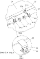
- the figure 7 is a view of detail C of the figure 6 showing the constituent elements of the support (34a) bolted to the concrete ring in the operational position.
- the figure 8 is an exploded view of the support (34a) of the figure 6 .
- the figure 9a is an overview of the installation with the reinforcement sole and the cleaning door with the location of one of the two supports glued and installed on the reinforcement sole of the cleaning door (9).
- the figure 9b is a view of Detail D of the figure 9a .
- the figure 10 is a schematic overall perspective view of the deflector according to the invention, in a situation of assembly on site and in partial exploded view, according to the second solution of the embodiment of the plating arm located below the protective sheet of the deflector .
- the deflector assembly consists of several deflector elements ( fig. 3 ref.1a 1b) independent of each other but able to be positioned one after the other in a continuous manner around and against the feet of the wall ( fig.1 , 2 and 10 ref.14) of the structure.
- the deflector assembly rests on the seat of the tank (23) and is held thereto by supports (6), which can be adjusted along three axes, and capable of adjusting the vertical or horizontal space between the independent deflector elements in their operative positions.
- Each deflector element ( fig. 3 ref.1a 1b) which constitutes the deflector assembly comprises at least, along one of its lateral edges, cover elements ( fig.4 ref. 7) and ( fig.4 ref.8) capable of covering the empty space up to the adjacent element.
- the deflector ( fig.1 and 10 ref.1) mainly consists of a protective sheet formed on two sides.
- the faces are at two angular positions.
- a face inclined at 15° minimum ( fig.1 and 10 ref. 1), and a revolution adapted to the radius of the tank and, an anti-drip profile with vertical edge in the lower part ( fig.1 and 10 ref. 3), restricting flow towards the ground or gutter ( fig.2 ref.26).
- the minimum 15° inclination of the deflector ( fig.1 and 10 ref.1) makes it possible to avoid and pass under most of the elements fixed to the storage tank, stairs, taps, etc...
- the shape and slope of the deflectors can be modified according to the obstacles encountered such as the cleaning door ( fig.3 ref.27) or the presence of reinforcement plates ( fig.3 ref.10 11) welded to the wall (14) of the tank and any other existing elements on site.
- the deflector plates (1) are then cut out and the installation of a nitrile seal can ensure the tightness of these particular areas.
- this cladding arm is located above the protective sheet of the deflector, and this inclined sheet (1) is equipped with this holding/cladding arm ( fig.2 ref.5) (visible in the background) serving primarily to hold the deflector (1) in its operational position and, secondly, to adjust the pressure necessary for the correct application of the seal ( fig.1 ref.2) on the wall (14) of the tank.
- this holding/cladding arm fig.2 ref.5 (visible in the background) serving primarily to hold the deflector (1) in its operational position and, secondly, to adjust the pressure necessary for the correct application of the seal ( fig.1 ref.2) on the wall (14) of the tank.
- the holding arm is articulated at its two ends by axes ( fig.1 ref.31a 31b) inserted in end caps ( fig.1 ref.37 38) allowing rotation of the assembly in order to disunite the magnet (or other reversible fixing means) ( fig.1 ref.12) to the magnetic wall (14).
- the ends of the holding arm are on its lower part and on the deflector side, bolted ( fig.1 ref.35a 41a) and on its upper part, equipped with the magnet (or other means of reversible fixing) ( fig.1 ref.12)
- All of the elements making up the retaining arm are attached to the turnbuckle ( fig.1 ref.29) by clevises ( fig.1 ref.39a 39b), which allows adjustment by rotation of the turnbuckle in order to obtain a good application of the joint ( fig.1 ref.2).
- the turnbuckle ( fig.1 ref.29) is the element which makes it possible to refine the application of the joint ( fig.1 ref.2) on the wall (14), by screwing/unscrewing.
- the holding arms (5) are located above the deflector (1), when the deflector is in the operational position, and are capable of coming into contact against the wall (14) above the seal ( fig.1 ref.2) by a rotation on its axis ( fig.1 ref.31b).
- the deflector intended for a metallic structural wall (14) is such that at least the holding arm ( fig.2 ref.5) comprises at its distal end at least one magnet (or other reversible fixing means) (12) able to be magnetically attached to the wall (14).
- the pressing arm (5) is located below the protective sheet: it is separable into at least two parts, the upper one (45) being fixed (46) below the sheet (1), such only by screwing, and the other lower one, the distal end of which is fixed to the support slab of the structural wall or to a base support (34e) (such as by welding as shown in the figure 10 ), or again, to the reinforcement sole of any accessory of this structure.
- the ends (45a, 45b) of the two said parts facing each other are able to "clip" together (45a, 45b) by pressing one against the other and moving one in the other during the installation of the deflector and to remain integral with each other despite their traction by the reaction of the joint which is compressed during their clipping, but these ends (45a, 45b) of the two said parts facing each other being able to be unclipped and therefore separated by a higher force traction.
- FIG. 10 An embodiment of these clip-on parts is represented schematically on the figure 10 where one (45a), located on the side of the upper part (45) of the pressing arm (5), has its end in the form of a partially open ring and capable of opening a little more elastically to receive the end of the other (45b), located on the side of the lower part of the arm (5) and which is in the form of a cylinder then being housed in the said ring and being blocked there by the closing effect of the latter ci behind the cylinder; in other embodiments, these cylindrical and partially open ring shapes can be reversed, the end of the upper part (45a) being able to be shaped like a cylinder and that of the lower part (45b) being shaped like a partially open ring.
- the entire deflector is cut into sections of length suitable for easy human transport, thus avoiding the intervention of machinery in the tank bowl.
- the material of the deflector is in stainless steel, aluminum or even in galvanized or other sheets, according to the customer's requests.
- the plates of the deflector according to the invention comprise a vertical rim (3), along the lower edge of the said inclined plates when the deflector is in the operational position: this rim can be either a joint called an anti-drip profile (3, 3a, 3b according to fig. 1 , 4 and 5 ), or a simple bending of the sheet (1) itself (depending on the fig.10 ).
- the elements placed on a tank or in a tank basin must not be one of the three elements of the fire triangle.
- the seal between the deflector and the tank wall ( fig.1 and 10 ref.14) is carried out using a nitrile seal ( fig.1 and 10 ref.2) or other material adapted to the environment, inserted in a curved profile ( fig.1 ref.4) which itself is fitted into the sheet (1) of the deflector.
- Each element of the deflector assembly which constitutes it comprises a plate ( fig.3 ref.7) ( fig.4 7 ) ( fig.5 ref.7 detail B) and a cover joint ( fig.4 ref.8) ( fig.5 ref.8 detail B) along one of its side edges and capable of covering an adjacent element.
- a cover plate ( fig.4 ref.7) is welded to the protection plate ( fig.4 ref.1a) thus making it possible to fill and protect the empty zone between the protective sheets ( fig.4 ref.1a and 1b).
- a joint (8) covering according to ( fig. 4 and 5 ), seal between two deflector elements in the operational position.
- the adjustable brackets ( fig.2 ref.6) ( fig.9a ref.6) are, on the one hand, fixed ( fig. 7 ref.32) to the deflectors such as by welding or screwing/bolting and on the other hand, fixed to the concrete ring ( fig. 2 ref.23) either by gluing, or by screwing or fixed on the steel reinforcement plate ( fig.9a ref.9) of the cleaning door by gluing, depending on the location where the support is installed and according to the customer's recommendations.
- brackets can be used to fix the deflector sheets.
- the supports of the deflector elements designated above (6) must allow adjustment on three axes, in order to adjust the vertical or horizontal space between the deflector elements in their operational positions.
- a single base support (34e) can be fixed to the concrete ring (23) (such as by screwing onto the side of this ring (23) as shown in this figure 10 ) and support both the distal ends of the lower parts of the support (6) of the protective sheet (1) and of the holding/placing arm (5) of this sheet (1), the upper parts (45,45') of this support (6) of sheet (1) and of the arm (5) being fixed (46,46') by screwing/bolting/riveting (or other means) on the underside of the sheet (1) inclined for protection; the sheet (1) supports (6) can be adjustable as in the embodiments described and shown in the fig.
- the upper parts (45,45') respectively of the supports (6) and the arms (5) can be identical and fixed under intermediate parts integral with the underside of the sheet ( 1) protection, these parts (not shown in the example of the figure 10 ) being of different heights to compensate for the difference in height between the arms (5), higher, and the supports (6), lower, so that the lower parts of these arms and these supports are also identical.
- the deflectors can be used on all structures requiring protection and maintenance of integrity.
- the materials used for making the deflector elements (1) can be zinc, Plexiglas or plastic if the fire risk is not proven and depending on the conditions of use.
- the variant can be made on the thicknesses of the materials used, their weights and their costs.
- the seals can be made with any flexible and extrudable product in order to match the area to be sealed and facilitate its insertion into a support section.
- the magnets can be of variable shapes, horseshoe, cylindrical or parallelepipedal, or even of a predefined shape when ordering and can be used both for the holding arms and for the supports.
- the fixings to the non-magnetic walls can be made with suction cups or glued plates, or fixed by any other reversible fixing means, to the walls of the structure depending on the nature of the support on which the deflector must be installed.
Landscapes
- Engineering & Computer Science (AREA)
- Architecture (AREA)
- Civil Engineering (AREA)
- Structural Engineering (AREA)
- General Engineering & Computer Science (AREA)
- Mechanical Engineering (AREA)
- Physics & Mathematics (AREA)
- Electromagnetism (AREA)
- Filling Or Discharging Of Gas Storage Vessels (AREA)
- Pressure Vessels And Lids Thereof (AREA)
- Specific Sealing Or Ventilating Devices For Doors And Windows (AREA)
- Gasket Seals (AREA)
Claims (10)
- Abweiser zum Schutz der Füße einer Metallwand (14) eines Bauwerks, die auf einer Platte (23) ruht, gegen das Eindringen von Flüssigkeiten, umfassend:- mindestens eine Schutzplatte (1), die sich von der genannten Wand (14) nach unten neigt, wenn sich der Abweiser in der Betriebsposition befindet,- mindestens eine biegsame Dichtung (2), die entlang des oberen Randes dieser nach unten geneigten Schutzplatte (1) angebracht ist, wenn sich der Deflektor in der Betriebsposition befindet, und die in dichten Kontakt mit der Strukturwand (14) kommen kann, deren Form sie nachgibt- mindestens ein Haltearm (5) der Platte (1), dessen eines Ende an der oberen Kante der Platte (1) befestigt ist und dessen anderes, sogenanntes distales Ende, mit einem Element der Struktur in umkehrbarer Weise verbunden und von diesem gelöst werden kann, wodurch der Abweiser abnehmbar wird,- der besagte Haltearm (5) ein Druckarm für die Platte (1) ist, der geeignet ist, die Dichtung (2) des oberen Randes der Platte (1) gegen die Wand (14) der Struktur zu drücken, wenn sich die Ablenkvorrichtung in der Betriebsposition befindet,- mindestens eine Stütze (6), die in Richtung des unteren Randes der Platte (1) angeordnet istdadurch gekennzeichnet, dass dieser Träger (6) in mindestens zwei Teile zerlegbar ist, die es ermöglichen, den Abweiser abnehmbar zu machen, von denen der obere unter der Platte (1) und der andere unter der Trägerplatte (23) der Strukturwand (14) oder an der Verstärkungssohle eines beliebigen Zubehörs dieser Struktur befestigt ist.
- Abweiser zum Schutz der Füße einer Metallstrukturwand (14) nach Anspruch 1, dadurch gekennzeichnet, dass der Haltearm (5), der ein Druckarm ist, der Platte (1) oberhalb dieser Platte (1) angeordnet ist und von oben darauf drückt, wenn sich der Abweiser in der Betriebsstellung befindet.
- Abweiser zum Schutz der Füße einer Metallstrukturwand (14) nach Anspruch 2, dadurch gekennzeichnet, dass zumindest der Haltearm (5) an seinem distalen Ende mindestens einen Magneten (12) aufweist, der magnetisch mit der Wand (14) verbunden werden kann.
- Abweiser nach einem der Ansprüche 2 und 3, dadurch gekennzeichnet, dass zumindest der Haltearm (5) ein Spannschloss (29) umfasst, das geeignet ist, den Druck einzustellen, der für das Pressen der Dichtung (2) ausgeübt werden muss.
- Abweiser zum Schutz der Füße einer Metallstrukturwand (14) nach Anspruch 1, dadurch gekennzeichnet, dass der Haltearm, der ein Druckarm ist, der Platte (1) unterhalb dieser Platte (1) angeordnet ist und in mindestens zwei Teile geteilt werden kann, von denen der obere (45) unterhalb der Platte (1) befestigt ist und der andere untere (5) an der Stützplatte (23) der Strukturwand (14) oder an der Verstärkungssohle eines beliebigen Zubehörs befestigt werden kann, an der Verstärkungssohle eines beliebigen Zubehörteils dieser Struktur befestigt werden kann, wobei die einander zugewandten Enden (45a, 45b) dieser Teile durch Aneinanderpressen und Ineinanderschieben bei der Positionierung des Ablenkers ineinander einrasten können und trotz ihres Ineinandergreifens durch die Reaktion der Dichtung (2), die bei ihrem Einrasten zusammengedrückt wird, miteinander verbunden bleiben.
- Deflektor nach einem der Ansprüche 1 bis 5, dadurch gekennzeichnet, dass die Deflektorplatte (1), wenn sie sich in der Betriebsposition befindet, eine Neigung aufweist, die einen Flüssigkeitsdurchfluss ohne Rückhaltung und einen Widerstand gegen die vertikale Belastung der Flüssigkeit ermöglicht.
- Deflektor nach einem der Ansprüche 1 bis 6, dadurch gekennzeichnet, dass er eine vertikale Kante (3) entlang der Unterkante der geneigten Platte (1) aufweist, wenn sich der Deflektor in der Betriebsposition befindet.
- Abweiser nach einem der Ansprüche 1 bis 7, dadurch gekennzeichnet, dass zumindest der verstellbare Träger (6) in drei Achsen verstellbar ist, um die Höhe der schrägen Schutzplatte (1) in Bezug auf die Platte (23) einzustellen und diese einerseits an der Wand (14) des zu schützenden Bauwerks und andererseits in einer schrägen Position entsprechend dem gewünschten Winkel zu halten.
- Ablenkeinheit, dadurch gekennzeichnet, dass sie aus mehreren Ablenkelementen nach einem der Ansprüche 1 bis 8 besteht, die voneinander unabhängig sind, aber nacheinander kontinuierlich um die Füße der Wand des Bauwerks herum und gegen diese positioniert werden können.
- Ablenkeinheit nach Anspruch 9, dadurch gekennzeichnet, dass jedes Ablenkelement, aus dem sie besteht, mindestens entlang einer seiner Seitenkanten Abdeckelemente (7 und 8) aufweist, die den leeren Raum bis zum benachbarten Element abdecken können.
Applications Claiming Priority (2)
| Application Number | Priority Date | Filing Date | Title |
|---|---|---|---|
| FR1800004A FR3076313A1 (fr) | 2018-01-02 | 2018-01-02 | Deflecteur de protection de pieds de structure |
| PCT/FR2018/053557 WO2019135046A1 (fr) | 2018-01-02 | 2018-12-28 | Perfectionnement a un deflecteur de protection de pieds de structure |
Publications (2)
| Publication Number | Publication Date |
|---|---|
| EP3735504A1 EP3735504A1 (de) | 2020-11-11 |
| EP3735504B1 true EP3735504B1 (de) | 2022-07-06 |
Family
ID=62873383
Family Applications (1)
| Application Number | Title | Priority Date | Filing Date |
|---|---|---|---|
| EP18842818.9A Not-in-force EP3735504B1 (de) | 2018-01-02 | 2018-12-28 | Verbesserung an einem deflektor zum schutz der füsse einer struktur |
Country Status (7)
| Country | Link |
|---|---|
| US (1) | US11377297B2 (de) |
| EP (1) | EP3735504B1 (de) |
| CN (1) | CN111655955B (de) |
| CA (1) | CA3087559A1 (de) |
| ES (1) | ES2927992T3 (de) |
| FR (1) | FR3076313A1 (de) |
| WO (1) | WO2019135046A1 (de) |
Family Cites Families (17)
| Publication number | Priority date | Publication date | Assignee | Title |
|---|---|---|---|---|
| NL70813C (de) * | ||||
| FR1300492A (fr) | 1960-09-17 | 1962-08-03 | Bayer Ag | Préparation des polyoxyméthylènes à poids moléculaire élevé par polymérisation du formaldéhyde |
| US5303523A (en) * | 1986-10-02 | 1994-04-19 | Hand Herbert H | Pest preventer for location on a structural foundation support or a structure supporting a food source |
| US5678362A (en) * | 1996-04-22 | 1997-10-21 | Owens-Corning Fiberglas Technology, Inc. | Termite control device and method |
| GB2351983A (en) * | 1999-07-14 | 2001-01-17 | Abolkheir Group | Barrier for protecting a structure from floods, snow or sand |
| DE20007583U1 (de) * | 2000-04-28 | 2000-11-02 | Koser, Wolfgang, Dr., 67269 Grünstadt | Korrosionsschutz für Lagertanks |
| US6612079B2 (en) * | 2000-06-21 | 2003-09-02 | Degarie Claude J. | Clarifier cover |
| US7621079B2 (en) * | 2005-01-14 | 2009-11-24 | Fukuvi Usa, Inc. | Water drainage component |
| US8166725B2 (en) * | 2008-09-11 | 2012-05-01 | Taylor Made Group, Llc | Flush glazed windshield mounting |
| US8650809B2 (en) * | 2009-05-06 | 2014-02-18 | Windtripper Corporation | Roof spoiler |
| US8312682B2 (en) * | 2009-08-21 | 2012-11-20 | Robert Mike Trotter | System and methods for providing a waterproofing form for structural waterproofing |
| US8322088B2 (en) * | 2009-11-04 | 2012-12-04 | Huang Daniel C L | Ventilated roofing structure |
| CN101734447A (zh) | 2009-12-03 | 2010-06-16 | 浙江大东吴集团建材构配件有限公司 | 一种混凝土粉料储存装置 |
| CN102031889B (zh) | 2010-11-19 | 2012-04-18 | 刘明瑞 | 一种新型钢板仓库 |
| JP5790244B2 (ja) * | 2011-07-26 | 2015-10-07 | 株式会社Ihi | タンク |
| FR3002927B1 (fr) * | 2013-03-06 | 2015-04-03 | Philippe Collay | Deflecteur de protection de pieds de structure |
| US9157243B2 (en) * | 2013-09-16 | 2015-10-13 | Wickright, Inc. | Construction device for releasing moisture from a building |
-
2018
- 2018-01-02 FR FR1800004A patent/FR3076313A1/fr not_active Withdrawn
- 2018-12-28 EP EP18842818.9A patent/EP3735504B1/de not_active Not-in-force
- 2018-12-28 ES ES18842818T patent/ES2927992T3/es active Active
- 2018-12-28 CN CN201880085408.XA patent/CN111655955B/zh not_active Expired - Fee Related
- 2018-12-28 US US16/959,269 patent/US11377297B2/en active Active
- 2018-12-28 CA CA3087559A patent/CA3087559A1/fr active Pending
- 2018-12-28 WO PCT/FR2018/053557 patent/WO2019135046A1/fr not_active Ceased
Also Published As
| Publication number | Publication date |
|---|---|
| US11377297B2 (en) | 2022-07-05 |
| CA3087559A1 (fr) | 2019-07-11 |
| ES2927992T3 (es) | 2022-11-14 |
| EP3735504A1 (de) | 2020-11-11 |
| FR3076313A1 (fr) | 2019-07-05 |
| WO2019135046A1 (fr) | 2019-07-11 |
| CN111655955A (zh) | 2020-09-11 |
| CN111655955B (zh) | 2022-03-29 |
| US20210053754A1 (en) | 2021-02-25 |
Similar Documents
| Publication | Publication Date | Title |
|---|---|---|
| EP3631283B1 (de) | Abgedichteter und wärmeisolierender tank | |
| EP3735504B1 (de) | Verbesserung an einem deflektor zum schutz der füsse einer struktur | |
| EP2583308A1 (de) | Dachdeckelement mit integriertem pv-modul | |
| EP0310488A1 (de) | Reinigungsöffnung für Anlagen zum Transportieren von Flüssigkeiten | |
| CA1249509A (fr) | Appareil d'intervention sur un robinet immerge | |
| FR3002927A1 (fr) | Deflecteur de protection de pieds de structure | |
| EP2636801B1 (de) | Löffel eines Löffelbaggers | |
| EP4301677B1 (de) | Mobile löschwasserreserve und zugehöriges installationsverfahren | |
| FR3021980A1 (fr) | Structure metallique pour un batiment et batiment, par exemple destine a l'elevage d'animaux, muni d'une telle structure | |
| EP2902555A1 (de) | Anschlussteil von einer Regenwasserkanalisationsleitung, Sichtschacht für Regenwasserkanalisationsleitungen, und gesamte Kanalisationsleitung, die einen solchen Sichtschacht umfasst | |
| EP0210899B1 (de) | Entfernbare Abdeckplatte für eine Öffnung, die nur über einen engen Zugang zugänglich ist | |
| WO2012069431A1 (fr) | Serre comprenant au moins un cheneau dispose au sommet de poteaux et fixe par vissage a des prolongements en hauteur des poteaux | |
| EP4124508B1 (de) | Dachbox und mit einer solchen dachbox ausgestattetes fahrzeug | |
| FR3030138A1 (fr) | Armoire, notamment de type telecom ou energie, comprenant une ossature porteuse et des parois d'habillage rapportees | |
| FR3060621A1 (fr) | Regard avaloir a tubulure coudee | |
| FR2941245A1 (fr) | Dispositif de regard destine a etre enterre, notamment pour compteur d'eau. | |
| WO2009034260A2 (fr) | Dispositif de stockage intégrant un réservoir monté sur remblai | |
| FR2948702A1 (fr) | Recuperateur d'eau de pluie hors sol | |
| FR2580012A1 (en) | Method for building a cellar, means for the implementation of this method and cellar thus obtained | |
| FR3025547A1 (fr) | Systeme de goulotte avec bac tampon integre pour realiser des piscines dites miroir | |
| FR2576936A1 (fr) | Dispositif de regulation d'un effluent pour regler le niveau d'un fluide | |
| FR2913438A1 (fr) | Boitier metallique pour separateur de graisses et/ou de liquides legers | |
| FR2771157A1 (fr) | Citerne a gaz destinee a etre enterree | |
| FR2825427A1 (fr) | Capuchon de protection d'une tige de scellement et procedes de fabrication et de mise en place d'un tel capuchon | |
| FR2752436A1 (fr) | Ouvrage prefabrique pour le captage et/ou le traitement de l'eau, ainsi que pour le stockage de tous liquides |
Legal Events
| Date | Code | Title | Description |
|---|---|---|---|
| STAA | Information on the status of an ep patent application or granted ep patent |
Free format text: STATUS: UNKNOWN |
|
| STAA | Information on the status of an ep patent application or granted ep patent |
Free format text: STATUS: THE INTERNATIONAL PUBLICATION HAS BEEN MADE |
|
| PUAI | Public reference made under article 153(3) epc to a published international application that has entered the european phase |
Free format text: ORIGINAL CODE: 0009012 |
|
| STAA | Information on the status of an ep patent application or granted ep patent |
Free format text: STATUS: REQUEST FOR EXAMINATION WAS MADE |
|
| 17P | Request for examination filed |
Effective date: 20200630 |
|
| AK | Designated contracting states |
Kind code of ref document: A1 Designated state(s): AL AT BE BG CH CY CZ DE DK EE ES FI FR GB GR HR HU IE IS IT LI LT LU LV MC MK MT NL NO PL PT RO RS SE SI SK SM TR |
|
| AX | Request for extension of the european patent |
Extension state: BA ME |
|
| DAV | Request for validation of the european patent (deleted) | ||
| DAX | Request for extension of the european patent (deleted) | ||
| GRAP | Despatch of communication of intention to grant a patent |
Free format text: ORIGINAL CODE: EPIDOSNIGR1 |
|
| STAA | Information on the status of an ep patent application or granted ep patent |
Free format text: STATUS: GRANT OF PATENT IS INTENDED |
|
| INTG | Intention to grant announced |
Effective date: 20220201 |
|
| GRAS | Grant fee paid |
Free format text: ORIGINAL CODE: EPIDOSNIGR3 |
|
| GRAA | (expected) grant |
Free format text: ORIGINAL CODE: 0009210 |
|
| STAA | Information on the status of an ep patent application or granted ep patent |
Free format text: STATUS: THE PATENT HAS BEEN GRANTED |
|
| AK | Designated contracting states |
Kind code of ref document: B1 Designated state(s): AL AT BE BG CH CY CZ DE DK EE ES FI FR GB GR HR HU IE IS IT LI LT LU LV MC MK MT NL NO PL PT RO RS SE SI SK SM TR |
|
| REG | Reference to a national code |
Ref country code: AT Ref legal event code: REF Ref document number: 1502989 Country of ref document: AT Kind code of ref document: T Effective date: 20220715 Ref country code: CH Ref legal event code: EP |
|
| REG | Reference to a national code |
Ref country code: DE Ref legal event code: R096 Ref document number: 602018037724 Country of ref document: DE |
|
| REG | Reference to a national code |
Ref country code: IE Ref legal event code: FG4D Free format text: LANGUAGE OF EP DOCUMENT: FRENCH |
|
| REG | Reference to a national code |
Ref country code: LT Ref legal event code: MG9D |
|
| REG | Reference to a national code |
Ref country code: NL Ref legal event code: FP |
|
| REG | Reference to a national code |
Ref country code: ES Ref legal event code: FG2A Ref document number: 2927992 Country of ref document: ES Kind code of ref document: T3 Effective date: 20221114 |
|
| PG25 | Lapsed in a contracting state [announced via postgrant information from national office to epo] |
Ref country code: SE Free format text: LAPSE BECAUSE OF FAILURE TO SUBMIT A TRANSLATION OF THE DESCRIPTION OR TO PAY THE FEE WITHIN THE PRESCRIBED TIME-LIMIT Effective date: 20220706 Ref country code: RS Free format text: LAPSE BECAUSE OF FAILURE TO SUBMIT A TRANSLATION OF THE DESCRIPTION OR TO PAY THE FEE WITHIN THE PRESCRIBED TIME-LIMIT Effective date: 20220706 Ref country code: PT Free format text: LAPSE BECAUSE OF FAILURE TO SUBMIT A TRANSLATION OF THE DESCRIPTION OR TO PAY THE FEE WITHIN THE PRESCRIBED TIME-LIMIT Effective date: 20221107 Ref country code: NO Free format text: LAPSE BECAUSE OF FAILURE TO SUBMIT A TRANSLATION OF THE DESCRIPTION OR TO PAY THE FEE WITHIN THE PRESCRIBED TIME-LIMIT Effective date: 20221006 Ref country code: LV Free format text: LAPSE BECAUSE OF FAILURE TO SUBMIT A TRANSLATION OF THE DESCRIPTION OR TO PAY THE FEE WITHIN THE PRESCRIBED TIME-LIMIT Effective date: 20220706 Ref country code: LT Free format text: LAPSE BECAUSE OF FAILURE TO SUBMIT A TRANSLATION OF THE DESCRIPTION OR TO PAY THE FEE WITHIN THE PRESCRIBED TIME-LIMIT Effective date: 20220706 Ref country code: FI Free format text: LAPSE BECAUSE OF FAILURE TO SUBMIT A TRANSLATION OF THE DESCRIPTION OR TO PAY THE FEE WITHIN THE PRESCRIBED TIME-LIMIT Effective date: 20220706 |
|
| REG | Reference to a national code |
Ref country code: AT Ref legal event code: MK05 Ref document number: 1502989 Country of ref document: AT Kind code of ref document: T Effective date: 20220706 |
|
| PG25 | Lapsed in a contracting state [announced via postgrant information from national office to epo] |
Ref country code: PL Free format text: LAPSE BECAUSE OF FAILURE TO SUBMIT A TRANSLATION OF THE DESCRIPTION OR TO PAY THE FEE WITHIN THE PRESCRIBED TIME-LIMIT Effective date: 20220706 Ref country code: IS Free format text: LAPSE BECAUSE OF FAILURE TO SUBMIT A TRANSLATION OF THE DESCRIPTION OR TO PAY THE FEE WITHIN THE PRESCRIBED TIME-LIMIT Effective date: 20221106 Ref country code: GR Free format text: LAPSE BECAUSE OF FAILURE TO SUBMIT A TRANSLATION OF THE DESCRIPTION OR TO PAY THE FEE WITHIN THE PRESCRIBED TIME-LIMIT Effective date: 20221007 |
|
| REG | Reference to a national code |
Ref country code: DE Ref legal event code: R097 Ref document number: 602018037724 Country of ref document: DE |
|
| PG25 | Lapsed in a contracting state [announced via postgrant information from national office to epo] |
Ref country code: SM Free format text: LAPSE BECAUSE OF FAILURE TO SUBMIT A TRANSLATION OF THE DESCRIPTION OR TO PAY THE FEE WITHIN THE PRESCRIBED TIME-LIMIT Effective date: 20220706 Ref country code: RO Free format text: LAPSE BECAUSE OF FAILURE TO SUBMIT A TRANSLATION OF THE DESCRIPTION OR TO PAY THE FEE WITHIN THE PRESCRIBED TIME-LIMIT Effective date: 20220706 Ref country code: DK Free format text: LAPSE BECAUSE OF FAILURE TO SUBMIT A TRANSLATION OF THE DESCRIPTION OR TO PAY THE FEE WITHIN THE PRESCRIBED TIME-LIMIT Effective date: 20220706 Ref country code: CZ Free format text: LAPSE BECAUSE OF FAILURE TO SUBMIT A TRANSLATION OF THE DESCRIPTION OR TO PAY THE FEE WITHIN THE PRESCRIBED TIME-LIMIT Effective date: 20220706 Ref country code: AT Free format text: LAPSE BECAUSE OF FAILURE TO SUBMIT A TRANSLATION OF THE DESCRIPTION OR TO PAY THE FEE WITHIN THE PRESCRIBED TIME-LIMIT Effective date: 20220706 |
|
| PLBE | No opposition filed within time limit |
Free format text: ORIGINAL CODE: 0009261 |
|
| STAA | Information on the status of an ep patent application or granted ep patent |
Free format text: STATUS: NO OPPOSITION FILED WITHIN TIME LIMIT |
|
| PG25 | Lapsed in a contracting state [announced via postgrant information from national office to epo] |
Ref country code: SK Free format text: LAPSE BECAUSE OF FAILURE TO SUBMIT A TRANSLATION OF THE DESCRIPTION OR TO PAY THE FEE WITHIN THE PRESCRIBED TIME-LIMIT Effective date: 20220706 Ref country code: EE Free format text: LAPSE BECAUSE OF FAILURE TO SUBMIT A TRANSLATION OF THE DESCRIPTION OR TO PAY THE FEE WITHIN THE PRESCRIBED TIME-LIMIT Effective date: 20220706 |
|
| 26N | No opposition filed |
Effective date: 20230411 |
|
| PG25 | Lapsed in a contracting state [announced via postgrant information from national office to epo] |
Ref country code: AL Free format text: LAPSE BECAUSE OF FAILURE TO SUBMIT A TRANSLATION OF THE DESCRIPTION OR TO PAY THE FEE WITHIN THE PRESCRIBED TIME-LIMIT Effective date: 20220706 |
|
| REG | Reference to a national code |
Ref country code: DE Ref legal event code: R119 Ref document number: 602018037724 Country of ref document: DE |
|
| PGFP | Annual fee paid to national office [announced via postgrant information from national office to epo] |
Ref country code: FR Payment date: 20230627 Year of fee payment: 5 |
|
| REG | Reference to a national code |
Ref country code: CH Ref legal event code: PL |
|
| REG | Reference to a national code |
Ref country code: NL Ref legal event code: MM Effective date: 20230101 |
|
| GBPC | Gb: european patent ceased through non-payment of renewal fee |
Effective date: 20221228 |
|
| REG | Reference to a national code |
Ref country code: BE Ref legal event code: MM Effective date: 20221231 |
|
| PG25 | Lapsed in a contracting state [announced via postgrant information from national office to epo] |
Ref country code: SI Free format text: LAPSE BECAUSE OF FAILURE TO SUBMIT A TRANSLATION OF THE DESCRIPTION OR TO PAY THE FEE WITHIN THE PRESCRIBED TIME-LIMIT Effective date: 20220706 Ref country code: LU Free format text: LAPSE BECAUSE OF NON-PAYMENT OF DUE FEES Effective date: 20221228 |
|
| PG25 | Lapsed in a contracting state [announced via postgrant information from national office to epo] |
Ref country code: NL Free format text: LAPSE BECAUSE OF NON-PAYMENT OF DUE FEES Effective date: 20230101 |
|
| PG25 | Lapsed in a contracting state [announced via postgrant information from national office to epo] |
Ref country code: LI Free format text: LAPSE BECAUSE OF NON-PAYMENT OF DUE FEES Effective date: 20221231 Ref country code: IE Free format text: LAPSE BECAUSE OF NON-PAYMENT OF DUE FEES Effective date: 20221228 Ref country code: GB Free format text: LAPSE BECAUSE OF NON-PAYMENT OF DUE FEES Effective date: 20221228 Ref country code: DE Free format text: LAPSE BECAUSE OF NON-PAYMENT OF DUE FEES Effective date: 20230701 Ref country code: CH Free format text: LAPSE BECAUSE OF NON-PAYMENT OF DUE FEES Effective date: 20221231 |
|
| PG25 | Lapsed in a contracting state [announced via postgrant information from national office to epo] |
Ref country code: BE Free format text: LAPSE BECAUSE OF NON-PAYMENT OF DUE FEES Effective date: 20221231 |
|
| REG | Reference to a national code |
Ref country code: ES Ref legal event code: FD2A Effective date: 20240126 |
|
| PG25 | Lapsed in a contracting state [announced via postgrant information from national office to epo] |
Ref country code: IT Free format text: LAPSE BECAUSE OF NON-PAYMENT OF DUE FEES Effective date: 20221228 |
|
| PG25 | Lapsed in a contracting state [announced via postgrant information from national office to epo] |
Ref country code: ES Free format text: LAPSE BECAUSE OF NON-PAYMENT OF DUE FEES Effective date: 20221229 |
|
| PG25 | Lapsed in a contracting state [announced via postgrant information from national office to epo] |
Ref country code: HR Free format text: LAPSE BECAUSE OF FAILURE TO SUBMIT A TRANSLATION OF THE DESCRIPTION OR TO PAY THE FEE WITHIN THE PRESCRIBED TIME-LIMIT Effective date: 20220706 Ref country code: ES Free format text: LAPSE BECAUSE OF NON-PAYMENT OF DUE FEES Effective date: 20221229 Ref country code: CY Free format text: LAPSE BECAUSE OF FAILURE TO SUBMIT A TRANSLATION OF THE DESCRIPTION OR TO PAY THE FEE WITHIN THE PRESCRIBED TIME-LIMIT Effective date: 20220706 |
|
| PG25 | Lapsed in a contracting state [announced via postgrant information from national office to epo] |
Ref country code: MK Free format text: LAPSE BECAUSE OF FAILURE TO SUBMIT A TRANSLATION OF THE DESCRIPTION OR TO PAY THE FEE WITHIN THE PRESCRIBED TIME-LIMIT Effective date: 20220706 Ref country code: HU Free format text: LAPSE BECAUSE OF FAILURE TO SUBMIT A TRANSLATION OF THE DESCRIPTION OR TO PAY THE FEE WITHIN THE PRESCRIBED TIME-LIMIT; INVALID AB INITIO Effective date: 20181228 |
|
| PG25 | Lapsed in a contracting state [announced via postgrant information from national office to epo] |
Ref country code: MC Free format text: LAPSE BECAUSE OF FAILURE TO SUBMIT A TRANSLATION OF THE DESCRIPTION OR TO PAY THE FEE WITHIN THE PRESCRIBED TIME-LIMIT Effective date: 20220706 |
|
| PG25 | Lapsed in a contracting state [announced via postgrant information from national office to epo] |
Ref country code: MC Free format text: LAPSE BECAUSE OF FAILURE TO SUBMIT A TRANSLATION OF THE DESCRIPTION OR TO PAY THE FEE WITHIN THE PRESCRIBED TIME-LIMIT Effective date: 20220706 |
|
| PG25 | Lapsed in a contracting state [announced via postgrant information from national office to epo] |
Ref country code: BG Free format text: LAPSE BECAUSE OF FAILURE TO SUBMIT A TRANSLATION OF THE DESCRIPTION OR TO PAY THE FEE WITHIN THE PRESCRIBED TIME-LIMIT Effective date: 20220706 |
|
| PG25 | Lapsed in a contracting state [announced via postgrant information from national office to epo] |
Ref country code: MT Free format text: LAPSE BECAUSE OF FAILURE TO SUBMIT A TRANSLATION OF THE DESCRIPTION OR TO PAY THE FEE WITHIN THE PRESCRIBED TIME-LIMIT Effective date: 20220706 |
|
| PG25 | Lapsed in a contracting state [announced via postgrant information from national office to epo] |
Ref country code: FR Free format text: LAPSE BECAUSE OF NON-PAYMENT OF DUE FEES Effective date: 20231231 |
|
| PG25 | Lapsed in a contracting state [announced via postgrant information from national office to epo] |
Ref country code: FR Free format text: LAPSE BECAUSE OF NON-PAYMENT OF DUE FEES Effective date: 20231231 |
|
| PG25 | Lapsed in a contracting state [announced via postgrant information from national office to epo] |
Ref country code: TR Free format text: LAPSE BECAUSE OF FAILURE TO SUBMIT A TRANSLATION OF THE DESCRIPTION OR TO PAY THE FEE WITHIN THE PRESCRIBED TIME-LIMIT Effective date: 20220706 |