EP4301677B1 - Mobile löschwasserreserve und zugehöriges installationsverfahren - Google Patents
Mobile löschwasserreserve und zugehöriges installationsverfahren Download PDFInfo
- Publication number
- EP4301677B1 EP4301677B1 EP22720449.2A EP22720449A EP4301677B1 EP 4301677 B1 EP4301677 B1 EP 4301677B1 EP 22720449 A EP22720449 A EP 22720449A EP 4301677 B1 EP4301677 B1 EP 4301677B1
- Authority
- EP
- European Patent Office
- Prior art keywords
- endoskeleton
- flexible membrane
- shipping container
- water
- removable
- Prior art date
- Legal status (The legal status is an assumption and is not a legal conclusion. Google has not performed a legal analysis and makes no representation as to the accuracy of the status listed.)
- Active
Links
Images


Classifications
-
- B—PERFORMING OPERATIONS; TRANSPORTING
- B65—CONVEYING; PACKING; STORING; HANDLING THIN OR FILAMENTARY MATERIAL
- B65D—CONTAINERS FOR STORAGE OR TRANSPORT OF ARTICLES OR MATERIALS, e.g. BAGS, BARRELS, BOTTLES, BOXES, CANS, CARTONS, CRATES, DRUMS, JARS, TANKS, HOPPERS, FORWARDING CONTAINERS; ACCESSORIES, CLOSURES, OR FITTINGS THEREFOR; PACKAGING ELEMENTS; PACKAGES
- B65D90/00—Component parts, details or accessories for large containers
- B65D90/02—Wall construction
- B65D90/04—Linings
- B65D90/046—Flexible liners, e.g. loosely positioned in the container
Definitions
- the invention relates to the field of firefighting.
- it relates to a mobile fire water reserve and its associated installation method.
- Firefighting requires the presence of numerous firefighting water reserves throughout an area. This ensures that in the event of a fire, firefighters have the necessary volume of water available. This volume must be accessible to firefighters at all times and positioned in a single location to avoid requiring additional maneuvers for firefighting teams.
- a flexible fire reserve requires a ground installation footprint of approximately 50 m2 with a direct outlet and approximately 65 m2 with a remote outlet.
- the invention aims to solve, at least partially, this need.
- each of the plurality of first vertical beams is fixed to the maritime container by irremovable fixing means so as to arrange the first vertical beams two by two facing each other, on either side of the internal faces of the side walls.
- every second cross beam is attached to the main part of the endoskeleton by the removable attachment means.
- the main portion of the endoskeleton further comprises a plurality of third vertical beams.
- each of the plurality of third vertical beams is fixed to the internal faces of the rear wall by irremovable fixing means.
- the main part of the endoskeleton further comprises at least one fourth horizontal beam, which is fixed to the first vertical beams and to the third vertical beams by irremovable fixing means, so as to connect the first vertical beams and the third vertical beams together, without being in direct contact with the internal walls of the maritime container.
- each second transverse beam is fixed to the fourth horizontal beam by removable fixing means.
- the fourth horizontal beam and the second transverse beam are arranged substantially halfway up the maritime container.
- the front wall comprises at least one access door to the interior of the maritime container
- the main part of the endoskeleton further comprises a plurality of fifth horizontal beams and at least one sixth vertical beam, which are fixed to the internal face of the front wall by irremovable fixing means.
- the fire water reserve further comprises a plurality of attachment elements, for example attachment hooks, which are fixed to the maritime container and/or to the endoskeleton, and the flexible membrane further comprises a plurality of anchoring elements, for example attachment eyelets, which are configured to be attached by the plurality of attachment elements.
- the removable fastening means are configured to pass tightly through the connection holes of the flexible membrane.
- the fire water reserve further comprises a suction pipe and a filling pipe which respectively define a sealed passage through at least one of the walls of the maritime container, between the flexible membrane and the exterior of the maritime container, the suction pipe being intended to bring water out of the flexible membrane to a device external to the shipping container and which is adapted to consume water, the filling line being intended to bring water into the flexible membrane from a supply source external to the shipping container and which is adapted to deliver water.
- One of the objectives of this invention is to considerably reduce the land footprint of ground-based fire reserves.
- the inventors propose a fire water reserve that is formed in a maritime container.
- the footprint of a standard maritime container is around 15 m2 for an available volume of 33 m3
- the footprint of a flexible fire reserve is around 50 m2 with a direct connection and around 65 m2 with a remote connection, for a water volume of 30 m3 .
- the installation of a fire water reserve according to the invention can be carried out with handling equipment which reduces the installation time.
- the invention relates to a mobile fire water reserve as functionally illustrated in the Figure 1 .
- the fire water reserve 100 comprises a maritime container 110, an endoskeleton 120 and a flexible membrane 130.
- the maritime container 110 is functionally coupled to the endoskeleton 120 and the endoskeleton 120 is functionally coupled to the flexible membrane 130.
- FIG. 2 illustrates the 110 shipping container.
- the maritime container 110 is of a type known per se, such as an ISO standardized maritime container for general use (also called a “dry” container), for example according to the NF ISO 668 standard.
- the maritime container 110 has a front wall 111, a rear wall 112, a top wall 113, a bottom wall 114 and side walls 115.
- the front wall 111 comprises at least one access door 111a to the interior of the maritime container 110.
- the external face of the lower wall 114 is intended to rest on the ground.
- the fire water reserve 100 is mobile and can be moved from one place to another by a lifting device such as a crane.
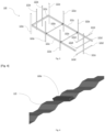
- FIG. 3 illustrates the endoskeleton 120.
- the endoskeleton 120 is arranged inside the shipping container 110. Furthermore, the endoskeleton 120 is designed to reinforce the shipping container 110 from the inside.
- the endoskeleton 120 is made of metal.
- the endoskeleton 120 is made of composite material.
- the composite material may be reinforced with fibers to locally stiffen the endoskeleton 120.
- the endoskeleton 120 may be formed from other materials without requiring substantial modifications to the invention.
- the flexible membrane 130 is designed to be hooked inside the maritime container 110 so as to move from an initial position to a hooking position.
- the flexible membrane 130 is substantially unfolded flat.
- the flexible membrane 130 is substantially folded to take the shape of a hanging pocket which has an upper opening towards the upper wall 113 so as to form a reservoir for storing water.
- the flexible membrane 130 is waterproof. Thus, the attachment position of the flexible membrane 130 prevents any risk of water leaking out of the tank, except through the upper opening.
- the flexible membrane 130 is made of Polyvinyl chloride (PVC).
- the flexible membrane 130 is made of Ethylene Propylene Diene Monomer (EPDM).
- EPDM Ethylene Propylene Diene Monomer
- the flexible membrane 130 may be formed from other materials without requiring substantial modifications of the invention.
- the endoskeleton 120 comprises a main part 121 and a removable part 122.
- the removable part 122 of the endoskeleton 120 is fixed to the main part 121 of the endoskeleton 120 by removable fixing means.
- Removable fixing means means fixing means which allow reversible fastening to be achieved.
- the removable fixing means are known fixing means by bolting bolt/nut assemblies.
- the removable fixing means are known screw fixing means.
- the removable part 122 of the endoskeleton 120 is arranged inside the tank and is configured to absorb all or part of the forces exerted by the pressure of the water on the internal faces of the side walls 115.
- the flexible membrane 130 comprises a plurality of connection holes 131 which are configured to allow the passage of all or part of the removable fixing means through it, when the flexible membrane 130 is in the hooking position.
- connection holes 131 are formed by stitching into the flexible membrane 130.
- the removable fixing means are configured to pass in a sealed manner through the connection holes 131 of the flexible membrane 130.
- sealing is achieved by at least one O-ring which is inserted between the removable fixing means and the flexible membrane 130.
- the main part 121 of the endoskeleton 120 comprises a plurality of first vertical beams 121a and the removable part 122 of the endoskeleton 120 comprises at least one second transverse beam 122a.
- each of the plurality of first vertical beams 121a is fixed to the maritime container 110 by irremovable fixing means so as to arrange the first vertical beams 121a two by two facing each other, on either side of the internal faces of the side walls 115.
- Immovable fixing means means fixing means which enable irreversible attachment to be achieved.
- the irremovable fixing means are known fixing means by welding.
- the irremovable fixing means are known fixing means by gluing.
- FIG. 4 illustrates a side wall 115 on which a first vertical beam 121a has been fixed.
- the side walls 115 have a trapezoidal section so that the first vertical beams 121a can be fixed in the space which separates two adjacent trapezoids, at the level of the large bases of the trapezoidal section.
- each of the plurality of first vertical beams 121a extends toward the inner face of the bottom wall 114 and toward the inner face of the top wall 113.
- all or part of the plurality of first vertical beams 121a comes into contact, at one of its ends, with the internal face of the upper wall 113.
- all or part of the plurality of first vertical beams 121a comes into contact, at one of its ends, with the internal face of the lower wall 114.
- all or part of the plurality of first vertical beams 121a comes into contact, respectively, at one of their ends, with the internal face of the upper wall 113 and the internal face of the lower wall 114.
- each second transverse beam 122a is fixed to the main part 121 of the endoskeleton 120 by the removable fixing means.
- each second transverse beam 122a extends between two first vertical beams 121a which are opposite each other.
- the main part 121 of the endoskeleton 120 further comprises a plurality of third vertical beams 121b.
- each of the plurality of third vertical beams 121b is fixed to the internal faces of the rear wall 112 by irremovable fixing means.
- each of the plurality of third vertical beams 121b extends toward the inner face of the lower wall 114 and towards the inner face of the upper wall 113.
- all or part of the plurality of third vertical beams 121b comes into contact, at one of its ends, with the internal face of the upper wall 113.
- all or part of the plurality of third vertical beams 121b comes into contact, at one of its ends, with the internal face of the lower wall 114.
- all or part of the plurality of third vertical beams 121b comes into contact, respectively, at one of their ends, with the internal face of the upper wall 113 and the internal face of the lower wall 114.
- the main part 121 of the endoskeleton 120 further comprises at least a fourth horizontal beam 121c.
- the fourth horizontal beam 121c is fixed to the first vertical beams 121a and to the third vertical beams 121b by irremovable fixing means, so as to connect the first vertical beams 121a and the third vertical beams 121b together, without being in direct contact with the internal walls of the maritime container 110.
- each second transverse beam 122a is fixed to the fourth horizontal beam 121c by the removable fixing means.
- the fourth horizontal beam 121c and the second transverse beam 122a are arranged substantially halfway up the maritime container 110.
- the main part 121 of the endoskeleton 120 further comprises a plurality of fifth horizontal beams 121d and at least one sixth vertical beam 121e.
- the plurality of fifth horizontal beams 121d and at least one sixth vertical beam 121e are fixed to the internal face of the front wall 111 by irremovable fixing means, so as to reinforce the access door 111a.
- the fire water reserve 100 further comprises a plurality of attachment elements 123, for example hanging hooks, which are fixed in the upper part of the fire water reserve 100.
- the plurality of attachment elements 123 are fixed to the upper part of the internal faces of the front, rear and side walls 111, 112, 115 of the maritime container 110 by irremovable fixing means.
- the plurality of attachment elements 123 are fixed to the internal face of the upper wall 113 of the maritime container 110 by irremovable fixing means.
- the plurality of attachment elements 123 are fixed to the endoskeleton 120, for example to a rod element of the endoskeleton 120 which goes all the way around the inside of the maritime container 110.
- the flexible membrane 130 further comprises a plurality of anchoring elements 132, for example hanging eyelets, which are configured to be hung by the plurality of hanging elements 123.
- the fire water reserve 100 further comprises a suction line 140 and a filling line 150.
- the suction line 140 and the filling line 150 respectively define a sealed passage through at least one of the walls 111, 112, 113, 114, 115 of the maritime container 110, between the flexible membrane 130 and the exterior of the maritime container 110.
- the sealing is achieved by at least one sealing flange and at least one sealing counter-flange which are assembled so as to compress the flexible membrane 130 on either side.
- the suction line 140 is intended to bring water out of the flexible membrane 130 to a device external to the maritime container 110.
- the device is adapted to consume water.
- the filling line 150 is intended to bring water into the flexible membrane 130 from a supply source external to the maritime container 110.
- the supply source is adapted to deliver water.
- the invention also relates to a method of installing 200 the fire water reserve 100 as illustrated in the Figure 5 .
- the method 200 firstly comprises a step 210 of supplying a fire water reserve 100 as described above.
- the method 200 then comprises a step 220 of opening the access door 111a of the front wall 111.
- the method according to the invention makes it possible to carry out the installation with the access doors 111a open, until the installation is finalized and delivered to the site.
- the method 200 comprises a step 230 of removing the removable part 122 of the endoskeleton 120.
- the removal of the removable part 122 of the endoskeleton 120 makes it possible not to be hindered when installing the flexible membrane 130 inside the maritime container 110.
- the method 200 comprises a step 240 of attaching the plurality of anchoring elements 132 of the flexible membrane 130 to the plurality of attachment elements 123 of the main part 121 of the endoskeleton 120.
- the flexible membrane 130 does not obstruct the access door 111a which is left free of access.
- the method 200 comprises a step 250 of replacing the removable part 122 of the endoskeleton 120 on the main part 121 of the endoskeleton 120, so that the removable fixing means pass in a sealed manner through the connection holes 131 of the flexible membrane 130.
- the method 200 comprises a step 260 of placing the suction pipe 140 and the filling pipe 150, so as to define respectively, a sealed passage through at least one of the walls 111, 112, 113, 114, 115 of the maritime container 110, between the flexible membrane 130 and the exterior of the maritime container 110.
- the method 200 comprises a step of closing and sealing 270, from the outside, the access door 111a of the front wall 111.
- the anchoring elements 132 of the flexible membrane 130 are attached, which are associated with the plurality of attachment elements 123 of the main part 121 of the endoskeleton 120 which are located at the level of the internal face of the front wall 111.
- the access door 111a of the front wall 111 is closed by irremovable closing means, for example by welding.
- the method 200 comprises a step 280 of connecting the filling pipe 150 to a power source external to the maritime container 110 and which is adapted to deliver water.
- the invention may be the subject of numerous variants and applications other than those described above within the scope of the appended claims.
- the different structural and functional characteristics of each of the implementations described above should not be considered as combined and/or closely and/or inextricably linked to each other, but on the contrary as simple juxtapositions.
- the structural and/or functional characteristics of the different embodiments described above may be the subject in whole or in part of any different juxtaposition or any different combination.
- the flexible membrane 130 may comprise the plurality of attachment elements 123 while the fire water reserve 100 may comprise the plurality of anchoring elements 132.
- the access door 111a of the front wall 111 can be closed by removable closing means.
Landscapes
- Engineering & Computer Science (AREA)
- Mechanical Engineering (AREA)
- Fire-Extinguishing By Fire Departments, And Fire-Extinguishing Equipment And Control Thereof (AREA)
- Filling Or Discharging Of Gas Storage Vessels (AREA)
- Separation Using Semi-Permeable Membranes (AREA)
Claims (9)
- Mobile Löschwasserreserve (100), umfassend:- einen Seecontainer (110), aufweisend eine Vorderwand (111), eine Rückwand (112), eine obere Wand (113), eine untere Wand (114) und Seitenwände (115), wobei die Außenfläche der unteren Wand (114) dazu vorgesehen ist, auf dem Boden zu lagern,- ein Endoskelett (120), das im Inneren des Seebehälters (110) angeordnet ist und dazu entworfen ist, den Seebehälter (110) vom Inneren zu verstärken, und- eine wasserundurchlässige flexible Membran (130), die dazu entworfen ist, am Inneren des Seebehälters (110) eingehängt zu werden, um aus einer Anfangsposition, in der die Membran im Wesentlichen flach auseinanderfaltet ist, zu einer Aufhängeposition, in der die flexible Membran (130) im Wesentlichen zusammengefaltet ist, um eine Form einer hängenden Tasche anzunehmen, die dazu vorgesehen ist, ein Reservoir zum Aufbewahren von Wasser zu bilden, überzugehen,
wobei- das Endoskelett (120) einen Hauptteil (121) und einen abnehmbaren Teil (122) umfasst, wobei der abnehmbare Teil (122) des Endoskeletts (120) an dem Hauptteil (121) des Endoskeletts (120) durch abnehmbare Befestigungsmittel befestigt ist, und wenn die flexible Membran (130) in der Aufhängeposition ist, der abnehmbare Teil (122) des Endoskeletts (120) dazu konfiguriert ist, alle oder einen Teil von Kräften, die durch den Wasserdruck auf die Innenflächen der Seitenwände (115) ausgeübt werden, zu absorbieren,dadurch gekennzeichnet, dass die flexible Membran (130) eine Vielzahl von Verbindungslöchern (131) umfasst, die dazu konfiguriert sind, den Durchtritt aller oder eines Teils der abnehmbaren Befestigungsmittel durch sie zuzulassen, wenn die flexible Membran (130) in der Aufhängeposition ist,und dadurch gekennzeichnet, dass- die flexible Membran (130) in der Aufhängeposition eine obere Öffnung in Richtung der oberen Wand (113) des Seebehälters (110) aufweist, und- wenn die flexible Membran (130) in der Aufhängeposition ist, der abnehmbare Teil (122) des Endoskeletts (120) im Inneren des Reservoirs angeordnet ist. - Löschwasserreserve (100) nach Anspruch 1, wobei- der Hauptteil (121) des Endoskeletts (120) eine Vielzahl von ersten vertikalen Balken (121a) umfasst und- der abnehmbare Teil (122) des Endoskeletts (120) mindestens einen zweiten Querbalken (122a) umfasst,und wobeijeder der Vielzahl von ersten vertikalen Balken (121a) an dem Seebehälter (110) durch nicht abnehmbare Befestigungsmittel befestigt ist, um die ersten vertikalen Balken (121a) paarweise zueinander beidseitig von den Innenflächen der Seitenwände (115) anzuordnen,jeder zweite Querbalken (122a) an dem Hauptteil (121) des Endoskeletts (120) durch abnehmbare Befestigungsmittel befestigt ist.
- Löschwasserreserve (100) nach Anspruch 2, wobei der Hauptteil (121) des Endoskeletts (120) weiterhin eine Vielzahl von dritten vertikalen Balken (121b) umfasst,
wobei jeder der Vielzahl von dritten vertikalen Balken (121b) an den Innenflächen der Rückwand (112) durch nicht abnehmbare Befestigungsmittel befestigt ist. - Löschwasserreserve (100) nach Anspruch 3, wobei der Hauptteil (121) des Endoskeletts (120) weiterhin mindestens einen vierten horizontalen Balken (121c) umfasst,der an den ersten vertikalen Balken (121a) und an den dritten vertikalen Balken (121b) durch nicht abnehmbare Befestigungsmittel befestigt ist, um die ersten vertikalen Balken (121a) und die dritten vertikalen Balken (121b) miteinander zu verbinden, ohne in direktem Kontakt mit den Innenwänden des Seebehälters (110) zu sein,und wobeijeder zweite Querbalken (122a) an dem vierten horizontalen Balken (121c) durch abnehmbare Befestigungsmittel befestigt ist.
- Löschwasserreserve (100) nach Anspruch 4, wobei der vierte horizontale Balken (121c) und der zweite Querbalken (122a) im Wesentlichen auf halber Höhe des Seebehälters (110) angeordnet sind.
- Löschwasserreserve (100) nach einem der Ansprüche 1 bis 5, wobei die Vorderwand (111) mindestens eine Zugangstür (111a) zum Inneren des Seebehälters (110) umfasst, wobei der Hauptteil (121) des Endoskeletts (120) weiterhin eine Vielzahl von fünften horizontalen Balken (121d) und mindestens einen sechsten vertikalen Balken (121e) umfasst, die an der Innenfläche der Vorderwand (111) durch nicht abnehmbare Befestigungsmittel befestigt sind.
- Löschwasserreserve (100) nach einem der Ansprüche 1 bis 6, weiterhin umfassend eine Vielzahl von Aufhängeelementen (123), beispielsweise Aufhängehaken, die an dem Seebehälter (110) und/oder an dem Endoskelett (120) befestigt sind, und
die flexible Membran (130) weiterhin eine Vielzahl von Verankerungselementen (132), beispielsweise Verankerungsösen, umfasst, die dazu konfiguriert sind, durch die Vielzahl von Aufhängeelementen (123) aufgehängt zu werden. - Löschwasserreserve (100) nach einem der Ansprüche 1 bis 7, weiterhin umfassend eine Saugleitung (140) und eine Füllleitung (150), die jeweils einen dichten Durchtritt durch mindestens eine der Wände (111, 112, 113, 114, 115) des Seebehälters (110) zwischen der flexiblen Membran (130) und der Außenseite des Seebehälters (110) definieren, wobei die Saugleitung (140) dazu vorgesehen ist, Wasser außerhalb der flexiblen Membran (130) zu einer zu dem Seebehälter (110) externen Vorrichtung zu bringen, und die dazu angepasst ist, das Wasser zu verbrauchen, wobei die Füllleitung (150) dazu vorgesehen ist, das Wasser in die flexible Membran (130) von einer zu dem Seebehälter (110) externen Versorgungsquelle zu bringen, und die dazu angepasst ist, das Wasser abzugeben.
- Verfahren zur Installation (200) einer mobilen Löschwasserreserve (100), wobei das Verfahren umfasst:- einen Schritt eines Bereitstellens (210) einer mobilen Löschwasserreserve (100) gemäß einer Kombination der Ansprüche 6, 7 und 8,- einen Schritt eines Öffnens (220) der Zugangstür (111a) der Vorderwand (111),- einen Schritt eines Zurückziehens (230) des abnehmbaren Teils (122) des Endoskeletts (120),- einen Schritt eines Aufhängens (240) der Vielzahl von Verankerungselementen (132) der flexiblen Membran (130) an der Vielzahl von Aufhängeelementen (123) des Hauptteils (121) des Endoskeletts (120),- einen Schritt eines erneuten Platzierens (250) des abnehmbaren Teils (122) des Endoskeletts (120) an dem Hauptteil (121) des Endoskeletts (120), so dass die abnehmbaren Befestigungsmittel abdichtend durch die Verbindungslöcher (131) der flexiblen Membran (130) hindurchtreten,- einen Schritt eines Platzierens (260) der Saugleitung (140) und der Füllleitung (150), um jeweils einen dichten Durchtritt durch mindestens eine der Wände (111, 112, 113, 114, 115) des Seebehälters (110) zwischen der flexiblen Membran (130) und der Außenseite des Seebehälters (110) zu definieren,- einen Schritt eines Schließens und Verschließens (270) der Zugangstür (111a) der Vorderwand (111) zu der Außenseite und- einen Schritt eines Verbindens (280) der Füllleitung (150) mit einer externen Versorgungsquelle an dem Seebehälter (110), und die dazu angepasst ist, das Waser abzugeben.
Applications Claiming Priority (2)
| Application Number | Priority Date | Filing Date | Title |
|---|---|---|---|
| FR2103441A FR3121434B1 (fr) | 2021-04-02 | 2021-04-02 | Réserve d’eau incendie mobile et procédé d’installation associé |
| PCT/EP2022/058910 WO2022207941A1 (fr) | 2021-04-02 | 2022-04-04 | Réserve d'eau incendie mobile et procédé d'installation associé |
Publications (3)
| Publication Number | Publication Date |
|---|---|
| EP4301677A1 EP4301677A1 (de) | 2024-01-10 |
| EP4301677B1 true EP4301677B1 (de) | 2025-06-18 |
| EP4301677C0 EP4301677C0 (de) | 2025-06-18 |
Family
ID=75690625
Family Applications (1)
| Application Number | Title | Priority Date | Filing Date |
|---|---|---|---|
| EP22720449.2A Active EP4301677B1 (de) | 2021-04-02 | 2022-04-04 | Mobile löschwasserreserve und zugehöriges installationsverfahren |
Country Status (3)
| Country | Link |
|---|---|
| EP (1) | EP4301677B1 (de) |
| FR (1) | FR3121434B1 (de) |
| WO (1) | WO2022207941A1 (de) |
Family Cites Families (4)
| Publication number | Priority date | Publication date | Assignee | Title |
|---|---|---|---|---|
| JPS5247628Y2 (de) * | 1972-09-14 | 1977-10-28 | ||
| US4232803A (en) * | 1978-11-06 | 1980-11-11 | A.I.R. Foundation | Bulk material retaining system having plural retainers |
| AU2007101010B4 (en) * | 2007-05-30 | 2007-11-15 | Richard Johannes Cornelis Huisman | Water storage tank in shipping container |
| GB0812703D0 (en) * | 2008-07-11 | 2008-08-20 | Botham Dale M | Container wall reinforcement and flexible tank wall load reduction |
-
2021
- 2021-04-02 FR FR2103441A patent/FR3121434B1/fr active Active
-
2022
- 2022-04-04 WO PCT/EP2022/058910 patent/WO2022207941A1/fr not_active Ceased
- 2022-04-04 EP EP22720449.2A patent/EP4301677B1/de active Active
Also Published As
| Publication number | Publication date |
|---|---|
| WO2022207941A1 (fr) | 2022-10-06 |
| EP4301677A1 (de) | 2024-01-10 |
| FR3121434A1 (fr) | 2022-10-07 |
| FR3121434B1 (fr) | 2023-09-29 |
| EP4301677C0 (de) | 2025-06-18 |
Similar Documents
| Publication | Publication Date | Title |
|---|---|---|
| EP0392894A1 (de) | Unterirdisches rohrförmiges Gebilde und Verfahren zu seiner Herstellung | |
| EP3631283B1 (de) | Abgedichteter und wärmeisolierender tank | |
| EP4301677B1 (de) | Mobile löschwasserreserve und zugehöriges installationsverfahren | |
| FR2912162A1 (fr) | Dispositif pour recuperer les eaux de pluie d'un local | |
| EP1066435B1 (de) | Kompakter filterblock für schwimmbecken | |
| EP2933400A1 (de) | Schutzvorrichtung eines materiellen gutes, und verwendung einer solchen vorrichtung zum schützen eines materiellen gutes | |
| MC200143A1 (fr) | Ecran de protection d'un bâtiment à l'encontre desinondations | |
| FR3025535A1 (fr) | Ensemble de dispositifs de protection pour excavation | |
| FR2752142A1 (fr) | Dispositif de couverture en tissu polyester, tendu a l'interieur d'une cerce ou d'un cadre metallique, et qui est notamment destinee a couvrir les fosses a lisier | |
| EP0465354A1 (de) | Aufblasbares Bauwerk mit flüssigkeitsgefüllten Behältern | |
| FR2707686A1 (fr) | Tente de camping. | |
| FR2923852A1 (fr) | Module de paroi d'un bassin de piscine | |
| EP3735504B1 (de) | Verbesserung an einem deflektor zum schutz der füsse einer struktur | |
| FR2695157A1 (fr) | Système de bâchage de fosse, notamment pour fosse à lisier. | |
| WO2009034260A2 (fr) | Dispositif de stockage intégrant un réservoir monté sur remblai | |
| FR2753340A1 (fr) | Dispositif pour contenir et suspendre une charge d'un materiau, par exemple pot de fleur | |
| JP3778449B2 (ja) | 地下防火貯水槽 | |
| BE1002542A3 (fr) | Reservoir prefabrique, de structure mixte metal-beton, a poser sur le sol. | |
| BE1020157A3 (fr) | Dispositif amovible de retenue des eaux. | |
| FR3091889A1 (fr) | Elément rigide pour un système de couverture de piscine | |
| FR2941716A1 (fr) | Dispositif de chambre de raccordement | |
| EP1553229A1 (de) | Kanalisationsschacht und wasserdichte Dichtung dafür | |
| EP4290015A1 (de) | Flutungssperrsystem | |
| FR2836693A1 (fr) | Caveau funeraire | |
| FR2728926A1 (fr) | Caveau monobloc en materiau composite |
Legal Events
| Date | Code | Title | Description |
|---|---|---|---|
| STAA | Information on the status of an ep patent application or granted ep patent |
Free format text: STATUS: UNKNOWN |
|
| STAA | Information on the status of an ep patent application or granted ep patent |
Free format text: STATUS: THE INTERNATIONAL PUBLICATION HAS BEEN MADE |
|
| PUAI | Public reference made under article 153(3) epc to a published international application that has entered the european phase |
Free format text: ORIGINAL CODE: 0009012 |
|
| STAA | Information on the status of an ep patent application or granted ep patent |
Free format text: STATUS: REQUEST FOR EXAMINATION WAS MADE |
|
| 17P | Request for examination filed |
Effective date: 20231002 |
|
| AK | Designated contracting states |
Kind code of ref document: A1 Designated state(s): AL AT BE BG CH CY CZ DE DK EE ES FI FR GB GR HR HU IE IS IT LI LT LU LV MC MK MT NL NO PL PT RO RS SE SI SK SM TR |
|
| GRAP | Despatch of communication of intention to grant a patent |
Free format text: ORIGINAL CODE: EPIDOSNIGR1 |
|
| STAA | Information on the status of an ep patent application or granted ep patent |
Free format text: STATUS: GRANT OF PATENT IS INTENDED |
|
| DAV | Request for validation of the european patent (deleted) | ||
| DAX | Request for extension of the european patent (deleted) | ||
| INTG | Intention to grant announced |
Effective date: 20240307 |
|
| GRAJ | Information related to disapproval of communication of intention to grant by the applicant or resumption of examination proceedings by the epo deleted |
Free format text: ORIGINAL CODE: EPIDOSDIGR1 |
|
| STAA | Information on the status of an ep patent application or granted ep patent |
Free format text: STATUS: REQUEST FOR EXAMINATION WAS MADE |
|
| INTC | Intention to grant announced (deleted) | ||
| STAA | Information on the status of an ep patent application or granted ep patent |
Free format text: STATUS: EXAMINATION IS IN PROGRESS |
|
| 17Q | First examination report despatched |
Effective date: 20240830 |
|
| GRAP | Despatch of communication of intention to grant a patent |
Free format text: ORIGINAL CODE: EPIDOSNIGR1 |
|
| STAA | Information on the status of an ep patent application or granted ep patent |
Free format text: STATUS: GRANT OF PATENT IS INTENDED |
|
| INTG | Intention to grant announced |
Effective date: 20250217 |
|
| GRAS | Grant fee paid |
Free format text: ORIGINAL CODE: EPIDOSNIGR3 |
|
| GRAA | (expected) grant |
Free format text: ORIGINAL CODE: 0009210 |
|
| STAA | Information on the status of an ep patent application or granted ep patent |
Free format text: STATUS: THE PATENT HAS BEEN GRANTED |
|
| AK | Designated contracting states |
Kind code of ref document: B1 Designated state(s): AL AT BE BG CH CY CZ DE DK EE ES FI FR GB GR HR HU IE IS IT LI LT LU LV MC MK MT NL NO PL PT RO RS SE SI SK SM TR |
|
| REG | Reference to a national code |
Ref country code: GB Ref legal event code: FG4D Free format text: NOT ENGLISH |
|
| REG | Reference to a national code |
Ref country code: CH Ref legal event code: EP |
|
| REG | Reference to a national code |
Ref country code: DE Ref legal event code: R096 Ref document number: 602022016108 Country of ref document: DE |
|
| REG | Reference to a national code |
Ref country code: CH Ref legal event code: EP |
|
| REG | Reference to a national code |
Ref country code: IE Ref legal event code: FG4D Free format text: LANGUAGE OF EP DOCUMENT: FRENCH |
|
| U01 | Request for unitary effect filed |
Effective date: 20250712 |
|
| U07 | Unitary effect registered |
Designated state(s): AT BE BG DE DK EE FI FR IT LT LU LV MT NL PT RO SE SI Effective date: 20250718 |
|
| PG25 | Lapsed in a contracting state [announced via postgrant information from national office to epo] |
Ref country code: NO Free format text: LAPSE BECAUSE OF FAILURE TO SUBMIT A TRANSLATION OF THE DESCRIPTION OR TO PAY THE FEE WITHIN THE PRESCRIBED TIME-LIMIT Effective date: 20250918 Ref country code: GR Free format text: LAPSE BECAUSE OF FAILURE TO SUBMIT A TRANSLATION OF THE DESCRIPTION OR TO PAY THE FEE WITHIN THE PRESCRIBED TIME-LIMIT Effective date: 20250919 |
|
| PG25 | Lapsed in a contracting state [announced via postgrant information from national office to epo] |
Ref country code: HR Free format text: LAPSE BECAUSE OF FAILURE TO SUBMIT A TRANSLATION OF THE DESCRIPTION OR TO PAY THE FEE WITHIN THE PRESCRIBED TIME-LIMIT Effective date: 20250618 |
|
| PG25 | Lapsed in a contracting state [announced via postgrant information from national office to epo] |
Ref country code: RS Free format text: LAPSE BECAUSE OF FAILURE TO SUBMIT A TRANSLATION OF THE DESCRIPTION OR TO PAY THE FEE WITHIN THE PRESCRIBED TIME-LIMIT Effective date: 20250918 |
|
| PG25 | Lapsed in a contracting state [announced via postgrant information from national office to epo] |
Ref country code: IS Free format text: LAPSE BECAUSE OF FAILURE TO SUBMIT A TRANSLATION OF THE DESCRIPTION OR TO PAY THE FEE WITHIN THE PRESCRIBED TIME-LIMIT Effective date: 20251018 |
|
| PG25 | Lapsed in a contracting state [announced via postgrant information from national office to epo] |
Ref country code: SM Free format text: LAPSE BECAUSE OF FAILURE TO SUBMIT A TRANSLATION OF THE DESCRIPTION OR TO PAY THE FEE WITHIN THE PRESCRIBED TIME-LIMIT Effective date: 20250618 |
|
| PG25 | Lapsed in a contracting state [announced via postgrant information from national office to epo] |
Ref country code: CZ Free format text: LAPSE BECAUSE OF FAILURE TO SUBMIT A TRANSLATION OF THE DESCRIPTION OR TO PAY THE FEE WITHIN THE PRESCRIBED TIME-LIMIT Effective date: 20250618 |
|
| PG25 | Lapsed in a contracting state [announced via postgrant information from national office to epo] |
Ref country code: PL Free format text: LAPSE BECAUSE OF FAILURE TO SUBMIT A TRANSLATION OF THE DESCRIPTION OR TO PAY THE FEE WITHIN THE PRESCRIBED TIME-LIMIT Effective date: 20250618 |
|
| PG25 | Lapsed in a contracting state [announced via postgrant information from national office to epo] |
Ref country code: SK Free format text: LAPSE BECAUSE OF FAILURE TO SUBMIT A TRANSLATION OF THE DESCRIPTION OR TO PAY THE FEE WITHIN THE PRESCRIBED TIME-LIMIT Effective date: 20250618 |
|
| PG25 | Lapsed in a contracting state [announced via postgrant information from national office to epo] |
Ref country code: ES Free format text: LAPSE BECAUSE OF FAILURE TO SUBMIT A TRANSLATION OF THE DESCRIPTION OR TO PAY THE FEE WITHIN THE PRESCRIBED TIME-LIMIT Effective date: 20250618 |
|
| PLBE | No opposition filed within time limit |
Free format text: ORIGINAL CODE: 0009261 |
|
| STAA | Information on the status of an ep patent application or granted ep patent |
Free format text: STATUS: NO OPPOSITION FILED WITHIN TIME LIMIT |
|
| REG | Reference to a national code |
Ref country code: CH Ref legal event code: L10 Free format text: ST27 STATUS EVENT CODE: U-0-0-L10-L00 (AS PROVIDED BY THE NATIONAL OFFICE) Effective date: 20260430 |