EP4124508B1 - Dachbox und mit einer solchen dachbox ausgestattetes fahrzeug - Google Patents
Dachbox und mit einer solchen dachbox ausgestattetes fahrzeug Download PDFInfo
- Publication number
- EP4124508B1 EP4124508B1 EP22187040.5A EP22187040A EP4124508B1 EP 4124508 B1 EP4124508 B1 EP 4124508B1 EP 22187040 A EP22187040 A EP 22187040A EP 4124508 B1 EP4124508 B1 EP 4124508B1
- Authority
- EP
- European Patent Office
- Prior art keywords
- box
- vehicle
- cover
- skirt
- trunk
- Prior art date
- Legal status (The legal status is an assumption and is not a legal conclusion. Google has not performed a legal analysis and makes no representation as to the accuracy of the status listed.)
- Active
Links
Images
Classifications
-
- B—PERFORMING OPERATIONS; TRANSPORTING
- B61—RAILWAYS
- B61D—BODY DETAILS OR KINDS OF RAILWAY VEHICLES
- B61D17/00—Construction details of vehicle bodies
- B61D17/04—Construction details of vehicle bodies with bodies of metal; with composite, e.g. metal and wood body structures
- B61D17/12—Roofs
-
- B—PERFORMING OPERATIONS; TRANSPORTING
- B61—RAILWAYS
- B61C—LOCOMOTIVES; MOTOR RAILCARS
- B61C17/00—Arrangement or disposition of parts; Details or accessories not otherwise provided for; Use of control gear and control systems
Definitions
- the present invention relates to a roof box for a public transport vehicle.
- the present invention also relates to a vehicle equipped with such a box.
- Roof boxes are used in many applications to protect equipment located on the roofs of vehicles such as buses, trains, or trams.
- equipment protected include electrical control or transformation equipment designed to receive an electrical current supplied by a catenary from a pantograph, or fuel cell assemblies or thermal control devices such as air conditioners.
- These chests generally include a box, delimiting a reception space, closed by a cover formed of sheets riveted to the box which serves as a support for each of the sheets.
- This cover separates the interior of the chest from the exterior and thus plays a role in protecting the equipment contained in the chest.
- the different sheets of the cover are generally sealed together.
- the invention relates to a roof box according to claim 1.
- the trunk lid according to the invention thus protects the sealant by preventing it from being directly exposed to rain, detergents when cleaning the trunk and/or solar radiation. The risks of deterioration of the sealant, and therefore of water infiltration inside the trunk, are therefore reduced.
- the trunk has one or more of the characteristics of claims 2 to 8 taken in isolation or in all technically possible combinations.
- the vehicle is according to claim 10.
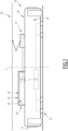
- FIG. 1 An example of a public transport vehicle 10 is shown in the Figure 1 .
- the vehicle 10 is, for example, a train, a tram or even a bus. However, other types of vehicles 10 are also possible.
- the vehicle 10 is, for example, an electric vehicle, that is to say a vehicle designed to be propelled by an electric motor 12.
- an electric vehicle that is to say a vehicle designed to be propelled by an electric motor 12.
- other propulsion modes are likely to be envisaged.
- the vehicle 10 comprises a body 14, a pantograph 16, at least one electrical equipment 18 and a roof box 20 accommodating said equipment 18.
- the vehicle 10 travels on a track, for example a railway track, by means of wheels 22.
- the electric motor 12 is configured to drive the wheels 22 of the vehicle 10 when the motor 12 is supplied with an electric current.
- the body 14 delimits at least one compartment 24 of the vehicle 10.
- the body 14 is configured to separate each compartment 24 from the exterior of the vehicle 10.
- the body 14 comprises, in particular, a roof 26 which delimits each compartment 24 in an elevation direction Z which is substantially vertical when the vehicle 10 is traveling on a horizontal track.
- the compartment 24 is intended to receive passengers, goods and/or equipment of the vehicle 10.
- the pantograph 16 is configured to come into contact with at least one catenary 28 when the vehicle 10 is in motion, and to receive a first electric current from the catenary(s) 28.
- the pantograph 20 is further configured to transmit the first electric current to the equipment 18.
- the equipment 18 is for example configured to convert the first current into a second current, and to transmit the second current to the electric motor 12.
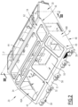
- FIG. 20 An example of a trunk 20 according to the invention is shown in more detail in the Figure 2 .
- the trunk 20 is fixed to the roof 26, for example by screwing.
- the trunk 20 extends in an elevation direction Z' substantially parallel to the elevation direction Z of the vehicle 10 when the trunk 20 is installed on the roof 26 of the vehicle 10.
- the terms "upper”, “lower”, “towards up”, “down”, “above” and “below” will have as reference said elevation direction Z' of the trunk 20.
- the trunk 20 comprises a box 30 and a cover 32 closing the box 30.
- the box 30 and the cover 32 are configured to delimit an internal volume 34 of the trunk 30, and to separate said internal volume 34 from the exterior of the trunk 20.
- the trunk 20 further comprises a mastic 36 disposed between the box 30 and the cover 32.
- the trunk 20 further comprises a support 38 arranged between the roof 26 of the vehicle 10 and the body 30.
- the support 38 thus has a lower face intended to be in contact with the vehicle 10, and an upper face, on which the body 30 rests.
- the support 38 comprises for example a set of feet 39 on which the body 30 rests, each foot 39 being configured to be fixed to the roof 26, for example in a removable manner, and to then be integral with the body 30.
- Each foot 39 is, for example, configured to be screwed to the roof 26.
- the box 30 is configured to support the cover 32.
- the box 30 is configured to maintain the cover 32 in a raised position relative to the body 14 of the vehicle 10 when the trunk 20 is mounted on the vehicle 10.
- the box 30 is preferably made of a metallic material.
- the box 30 is made of metal, for example aluminum, galvanized steel or carbon steel.
- the body 30 comprises a set of side walls 40, 41 each extending along a respective extension plane.
- the box 30 further comprises at least one intermediate wall 44 extending inside the internal volume 34 of the trunk 30 according to a respective extension plane.
- the intermediate wall(s) 44 divide(s) the internal volume 34 into at least two compartments. For example, each compartment is intended to receive a respective piece of equipment 18.
- the box 30 includes a bottom wall 45 intended to support the equipment(s) 18 received in the trunk 20.
- Each side wall 40, 41 rises from the bottom wall 45, according to its extension plane.
- the structure of the body 30, in particular the number, shape and arrangement of the side walls 40, 41 and the intermediate wall(s) 44 is likely to vary.
- the box 30 comprises four side walls 40, 41 whose respective extension planes extend substantially in the direction of extension Z' of the trunk 20.
- each side and/or intermediate wall 40, 41, 44 has a polygonal contour.
- each wall 40, 41, 44 is delimited in its respective extension plane by a closed polygonal contour.
- the box 30 comprises two side walls 40 in the shape of a non-regular hexagon and two side walls 41 in the shape of a rectangular shape.
- each wall 40, 41, 44 is rectangular, square, or even triangular.
- At least one side and/or intermediate wall 40, 41, 44 has a perimeter having at least one non-straight part, in particular an arc-shaped part.
- Each side and/or intermediate wall 40, 41, 44 extends in the elevation direction Z' of the trunk 20 between a lower edge 48 and an upper edge 49.
- At least one side and/or intermediate wall 40, 41, 44 is fixed at its lower edge 48 to said bottom wall 45, for example by riveting, screwing, or even welding.
- the bottom wall 45 has an internal face 50 oriented towards the internal volume 34 of the trunk 20 and an external face (not visible) opposite the internal face 50, the external face being intended to be opposite the roof 26 when the trunk 20 is installed on the vehicle 10.
- the bottom wall 45 also has a peripheral edge (not visible) connecting the internal face 50 and the external face of the bottom wall 45.
- the trunk 20 comprises a support 38
- the bottom wall 45 is fixed to said support, for example by means of rivets.
- At least one side wall 40, 41 extends on either side of the bottom wall 45, forming a so-called "water drop" profile.
- said side wall 40, 41 bears on the edge of the bottom wall 45, a marginal portion of the side wall 40, 41 extending on the side of the external face of the bottom wall 45 in the elevation direction Z'.
- said marginal portion goes below the external face of the bottom wall 45 in the elevation direction Z' over a height greater than 8 mm, for example between 8 mm and 10 mm, to constitute a water drop making it possible to vertically evacuate the residual water on the side walls 40, 41.
- said side wall 40, 41 also preferably extends below the level of the upper face of the support 38 in the elevation direction Z'.
- This overhang allows the water to run off along said side wall 40, 41 before falling towards the roof 26 and/or the ground, preventing the water from flowing along the base of the box 20, and in particular preventing water from stagnating at the level of the bottom wall 45 when the latter is present.
- the cover 32 is configured to close the box 30 and to delimit the internal volume 34 of the trunk 20 according to the elevation direction Z'.
- the cover 32 is supported by the box 30, for example at the level of at least one side wall 40, 41 and/or an intermediate wall 44. In the example shown in the Figure 2 , the cover 32 rests on the four side walls 40, 41 of the box 30.
- the cover 32 is for example welded onto the body 30. Alternatively, the cover 32 is fixed onto the body 30 by means of rivets.
- the cover 32 has an internal face 52A oriented at least in part towards the internal volume 34 of the trunk 20, and an external face 52B opposite the internal face 52A and oriented towards the outside of the trunk 20.
- the cover 32 has a central part 54 of the cover 32, the internal face 52A of which faces the internal volume 34 of the trunk 20.
- the cover 32 further comprises a peripheral skirt 56 located outside the body 30 and forming a rim of the cover 32.
- the cover 32 has at least one opening 58 passing through the central part 54.
- Each opening 58 allows access to the internal volume 34 of the trunk 20, and in particular to the equipment 18 located inside it, for example to carry out maintenance operations.
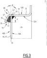
- Each opening 58 also allows access to the internal volume 34 of the trunk 20 during the manufacture of the latter, for example to fix the cover 32 to the body 30 by welding, a weld bead 59 (visible on the Figure 3 ) then extending inside the trunk 20.
- each opening 58 is at least partially closed by a panel (not shown).
- the cover 32 is formed from a set of sheets 62.
- Each sheet 62 has an internal face, forming a portion of the internal face 52A of the cover 32, and an external face, forming a portion of the external face 52B of the cover 32.
- Each sheet 62 is made of a metallic material, preferably aluminum. However, other materials are also possible.
- the sheets 62 are assembled together to form a set of single-piece sheets 62.
- the sheets 62 are welded to each other so as to form a set of single-piece sheets 62.
- the cover 32 is formed from a single sheet 62.
- the peripheral skirt 56 is preferably made in one piece with the sheet(s) 62.
- the peripheral skirt 56 is for example obtained by folding the sheet(s) 62.
- the peripheral skirt 56 extends outside the body 30 by forming a fallen edge around at least a portion of the upper edge 49 of the body 30.
- the peripheral skirt 56 extends downwards towards the roof 26 of the vehicle 10 and/or the ground.
- the peripheral skirt 56 extends over the entire circumference of the upper edge 49 of the body 30.
- the peripheral skirt 56 is here continuous.
- the peripheral skirt 56 surrounds the upper edge 49 of each side wall 40, 41 of the body 30.
- the peripheral skirt 56 covers the upper edge 49 by projecting outwards from the body 39 beyond the upper edge 49 and extending downwards.
- the free edge of the peripheral skirt 56 is located lower than the upper edge 49.
- the peripheral skirt 56 has a proximal portion 66, a distal portion 67 forming the fallen edge and a junction 68 connecting the proximal portion 66 and the distal portion 67.
- the junction 68 is for example an edge or a rounding.
- the proximal portion 66 extends in the continuity of the central part 54 of the cover 32 beyond the edge 47 of the side wall 40, 41, preferably over a length of between 5 mm and 10 mm, this length corresponding to the width of the proximal portion 66.
- the distal portion 67 is the portion of the peripheral skirt 56 which projects outwardly from the body 30 beyond the upper edge 49, extending downwardly.
- the free edge of the distal portion 67 (which defines the free edge of the peripheral skirt 56) is located lower than the upper edge 49.
- the peripheral skirt 56 defines with at least one side wall 40, 41 of the box 30 a chute 70 for receiving the mastic 36.
- the internal face 52A of the cover 32 is located opposite the external face 46B of the box 30.
- the chute 70 is delimited on the one hand by the cover 32, more precisely by the peripheral skirt 56, and on the other hand by the box 30, more precisely by one or more side wall(s) 40, 41.
- the chute 70 has a bottom 72 formed by the internal face 52A of the proximal portion 66 of the skirt 56.
- the bottom 72 has a width substantially equal to the length of the proximal portion 66.
- the chute 70 thus has, according to a section plane normal to the associated side wall 40, 41, a U-shaped or inverted V-shaped profile.
- This design helps prevent the ingress of water or cleaning products by promoting the flow of liquid by gravity.
- the chute 70 has a height H of between 15 mm and 20 mm, the height H being measured along the elevation direction Z' between the bottom 72 of the chute 70 and the free edge of the peripheral skirt 56.
- the chute 70 defines an angle ⁇ between 0° and 75°, preferably between 40° and 50°, advantageously substantially equal to 45°, the angle ⁇ being measured between the internal face 52A of the distal portion 67 of the skirt 56 and the external face 46B of the side wall 40, 41 opposite which said distal portion 67 is located.
- Such an angle ⁇ facilitates the application of the mastic 36 in the chute 70 and guarantees a good seal between the box 30 and the cover 32.
- the mastic 36 bears on the internal face 52A of the peripheral skirt 56, preferably on the internal face 52A of the proximal and distal portions 66, 67 of the skirt 56, and on the external face 46B of the wall 40, 41 which faces said internal face 52A.
- Sealant 36 is for example made of polymeric material, in particular polyurethane or silicone.
- the peripheral skirt 56 the mastic 36 is not directly exposed to solar radiation, in particular to ultraviolet rays. This prevents degradation of the mechanical properties of the mastic 36 and increases its service life.
- the manufacturing method comprises a step of providing the box 30, a step of providing the cover 32, a step of assembling the cover 32 on the box 30 and a step of applying the mastic 36 between the cover 32 and the box 30 to ensure the sealing of the trunk 20.
- the side walls 40, 41 and, optionally, the intermediate wall(s) 44 and the bottom wall 45 are assembled together by welding or by riveting.
- the sheets 62 are assembled together, preferably welded to each other, so as to form a set of single-piece sheets 62.
- At least a portion of the sheets 62 has undergone a folding step so as to form the peripheral skirt 56 of the cover 32.
- the cover 32 is placed on the box 30 so as to close said box 30.
- the cover 32 then rests on the box 30, for example at the level of at least one side wall 40, 41 and/or an intermediate wall 44.
- the cover 32 is then fixed to the body 30.
- the cover 32 is for example welded onto the body 30 or is fixed onto the body 30 by means of rivets.
- the presence of an opening 58 in the cover 32 allows an operator to have access to the interior volume 34 of the trunk 20 to carry out these fixings.
- the cover 32 and the box 30 define between them a chute 70 as described previously.
- the sealant 36 is applied, for example by means of a suitable gun, inside the chute 70.
- the box 30 is then fixed to a support 38.
- One or more electronic devices 18 are then arranged inside the trunk 20 and shutters are installed to close the openings 58.
- the trunk 20 is then fixed, for example screwed, to the roof 26 of the vehicle 10.
- the presence of the peripheral skirt 56 protects the sealant 36 from solar radiation, as well as from rain.
- the sealant 36 is also protected at least in part from the detergents used when cleaning the vehicle 10. The sealant 36 thus retains its mechanical properties for longer, which prevents degradation or partial or total decohesion of the sealant 36.
- the U-shaped or inverted V-shaped profile of the chute 70 promotes the flow of the liquid by gravity and prevents a rise by capillarity to the interior of the box 20, due to the length to be traveled in the chute 70.
- the roof box 20 according to the invention thus presents a very limited risk of water infiltration, and thus has increased durability.
- the peripheral skirt 56 does not extend over the entire circumference of the upper edge 49 of the body 30, but only over a portion of the circumference.
- the peripheral skirt 56 comprises a plurality of skirt portions spaced apart from each other, the peripheral skirt 56 then being discontinuous.
- each skirt portion extends opposite a respective side wall 40, 41.
- peripheral skirt 56 is devoid of a proximal portion 66.
- the junction 68 then directly connects the central part 54 of the cover 32 to the distal portion 67 of the skirt 56.
Landscapes
- Engineering & Computer Science (AREA)
- Mechanical Engineering (AREA)
- Automation & Control Theory (AREA)
- Transportation (AREA)
- Life Sciences & Earth Sciences (AREA)
- Wood Science & Technology (AREA)
- Fittings On The Vehicle Exterior For Carrying Loads, And Devices For Holding Or Mounting Articles (AREA)
- Body Structure For Vehicles (AREA)
- General Details Of Gearings (AREA)
Claims (10)
- Dachbox (20) für ein öffentliches Verkehrsmittel (10), insbesondere ein Schienenfahrzeug, wobei die Box (20) einen Innenraum (34) begrenzt und umfasst:- ein Gehäuse (30) mit einer Anordnung von Seitenwänden (40, 41), die sich jeweils entlang einer jeweiligen Ausdehnungsebene erstrecken, und- eine Abdeckung (32), die das Gehäuse (30) wenigstens teilweise verschließt, dadurch gekennzeichnet, dass die Abdeckung (32) wenigstens eine umlaufende Schürze (56) aufweist, die sich außerhalb des Gehäuses (30) befindet und mit wenigstens einer der Seitenwände (40, 41) eine Rinne (70) bildet, wobei die Box (20) ferner eine in der Rinne (70) angeordnete Dichtmasse (36) umfasst.
- Box (20) nach Anspruch 1, wobei die Schürze (56) einen distalen Abschnitt (67) umfasst, der eine umgeschlagene Kante bildet, wobei die Rinne (70) zwischen der umgeschlagenen Kante und der Seitenwand (40, 41) begrenzt ist, gegenüber der sich der distale Abschnitt (67) befindet.
- Box (20) nach Anspruch 2, wobei die Rinne (70) einen Winkel (α) zwischen 0° und 75°, vorzugsweise zwischen 40° und 50°, vorteilhafterweise im Wesentlichen gleich 45° definiert, wobei der Winkel (α) zwischen einer Innenfläche (52A) des distalen Abschnitts (67) der Schürze (56) und einer Außenfläche (46B) der Seitenwand (40, 41) gemessen wird, gegenüber der sich der distale Abschnitt (67) befindet.
- Box (20) nach Anspruch 2 oder 3, wobei die Schürze (56) ferner einen proximalen Abschnitt (66) umfasst, der sich zwischen dem distalen Abschnitt (67) und einem mittleren Teil (54) der Abdeckung (32) erstreckt, wobei der mittlere Teil (54) eine Innenfläche (52A) aufweist, die dem Innenvolumen (34) der Box (20) zugewandt ist, wobei sich der proximale Abschnitt (66) in der Kontinuität des mittleren Teils (54) erstreckt, wobei der proximale Abschnitt (66) vorzugsweise eine Breite zwischen 5 mm und 10 mm aufweist.
- Box (20) nach einem der vorhergehenden Ansprüche, wobei die Abdeckung (32) mittels einer Schweißnaht (59) und/oder Nieten an dem Gehäuse (30) befestigt ist.
- Box nach einem der vorhergehenden Ansprüche, wobei die Box (20) ferner einen Träger (38) umfasst, der sich zwischen einer Unterseite, die dazu vorgesehen ist, mit dem Fahrzeug (10) in Kontakt zu sein, und einer Oberseite in Kontakt mit dem Gehäuse (30) erstreckt, wobei sich wenigstens eine der Seitenwände (40, 41) des Gehäuses (30) vorzugsweise teilweise unterhalb der Oberseite des Trägers (38) erstreckt.
- Box nach einem der vorhergehenden Ansprüche, wobei die Abdeckung (32) eine Vielzahl von Metallblechen (62) umfasst, die miteinander verbunden, beispielsweise verschweißt sind, um eine einstückige Anordnung von Blechen (62) zu bilden.
- Box nach Anspruch 7, wobei die Schürze (56) mit wenigstens einem der Bleche (62) aus einem Stück gefertigt ist, wobei die Schürze (56) vorzugsweise durch Falten des Blechs (62) erhalten wird.
- Fahrzeug (10) für den öffentlichen Verkehr, insbesondere Schienenfahrzeug, mit wenigstens einer Dachbox (20) nach einem der vorhergehenden Ansprüche.
- Fahrzeug (10) nach Anspruch 9, wobei das Fahrzeug (10) ein Elektrofahrzeug ist, das einen Motor (12) und einen Stromabnehmer (16) umfasst, wobei der Motor (12) dazu ausgebildet ist, das Fahrzeug (10) anzutreiben, wobei der Stromabnehmer (16) dazu ausgebildet ist, einen ersten elektrischen Strom von einer Oberleitung (28) zu empfangen und den ersten Strom auf wenigstens eine Vorrichtung (18) zu übertragen, die im Innenraum (34) der Box (20) untergebracht ist, wobei die Vorrichtung (18) beispielsweise dazu ausgebildet ist, den ersten Strom in einen zweiten Strom umzuwandeln, der sich vom ersten Strom unterscheidet, und den Motor (12) mit dem zweiten Strom zu versorgen.
Applications Claiming Priority (1)
| Application Number | Priority Date | Filing Date | Title |
|---|---|---|---|
| FR2108159A FR3125786B1 (fr) | 2021-07-27 | 2021-07-27 | Coffre de toit et véhicule équipé d’un tel coffre |
Publications (2)
| Publication Number | Publication Date |
|---|---|
| EP4124508A1 EP4124508A1 (de) | 2023-02-01 |
| EP4124508B1 true EP4124508B1 (de) | 2025-05-07 |
Family
ID=77519375
Family Applications (1)
| Application Number | Title | Priority Date | Filing Date |
|---|---|---|---|
| EP22187040.5A Active EP4124508B1 (de) | 2021-07-27 | 2022-07-26 | Dachbox und mit einer solchen dachbox ausgestattetes fahrzeug |
Country Status (3)
| Country | Link |
|---|---|
| EP (1) | EP4124508B1 (de) |
| ES (1) | ES3031165T3 (de) |
| FR (1) | FR3125786B1 (de) |
Family Cites Families (6)
| Publication number | Priority date | Publication date | Assignee | Title |
|---|---|---|---|---|
| US3401647A (en) * | 1966-12-12 | 1968-09-17 | Midland Ross Corp | Hatches for railway covered hopper cars |
| JPS60104458A (ja) * | 1983-11-08 | 1985-06-08 | 株式会社日立製作所 | 箱形車体 |
| US5355806A (en) * | 1993-05-10 | 1994-10-18 | General Electric Company | Monocoque locomotive |
| DE10243091A1 (de) * | 2002-09-16 | 2004-04-01 | Oris Fahrzeugteile Hans Riehle Gmbh | Transportbehälter |
| CN202448994U (zh) * | 2012-02-15 | 2012-09-26 | 南车四方车辆有限公司 | 机车用顶盖及机车 |
| FR3050726B1 (fr) * | 2016-04-29 | 2018-05-25 | Alstom Transport Technologies | Coffre pour equipement electrique et vehicule ferroviaire comprenant un tel coffre |
-
2021
- 2021-07-27 FR FR2108159A patent/FR3125786B1/fr active Active
-
2022
- 2022-07-26 ES ES22187040T patent/ES3031165T3/es active Active
- 2022-07-26 EP EP22187040.5A patent/EP4124508B1/de active Active
Also Published As
| Publication number | Publication date |
|---|---|
| EP4124508A1 (de) | 2023-02-01 |
| ES3031165T3 (en) | 2025-07-04 |
| FR3125786A1 (fr) | 2023-02-03 |
| FR3125786B1 (fr) | 2025-10-24 |
Similar Documents
| Publication | Publication Date | Title |
|---|---|---|
| EP3377347B1 (de) | Landfahrzeug für öffentliches verkehrsmittel mit einem funktionellen oberen dachsystem | |
| FR2932831A1 (fr) | Systeme de montage de modules solaires | |
| FR3135956A1 (fr) | Caisse de vehicule automobile comportant un caisson de batterie électrique de traction | |
| EP4124508B1 (de) | Dachbox und mit einer solchen dachbox ausgestattetes fahrzeug | |
| EP3989688B1 (de) | Dachbox, mit einer solchen dachbox ausgestattetes fahrzeug und entsprechendes herstellungsverfahren | |
| EP3377349B1 (de) | Elektrische landfahrzeug für öffentliche verkehrsmittel, wie ein bus, mit internen stromspeichermodulen | |
| FR3135438A1 (fr) | Véhicule automobile avec déflecteur aéraulique sous plancher | |
| EP1054801A1 (de) | Anordnung des unterteils des innenraums eines kraftfahrzeuges | |
| EP3083372B1 (de) | Kraftfahrzeugkarosserieanordnung mit seitendichtung eines haubenentlüftungsgitters | |
| EP3219850B1 (de) | Verbessertes schwellensystem mit schalung, und schienenabschnitt, der ein solches system umfasst | |
| FR3099421A1 (fr) | Véhicule électrique sans plancher | |
| EP3656633B1 (de) | Waggon eines schienenfahrzeugs | |
| WO2011055078A1 (fr) | Partie avant de vehicule automobile comprenant une traverse inferieure de baie supportant le bord inferieur d'un pare-brise | |
| EP2050607B1 (de) | Lineares Dichtungselement und Kraftfahrzeug, das mit einer solchen Dichtung ausgestattet ist | |
| EP1616735B1 (de) | Vorrichtung zur Verhinderung des Wassereintritts in einem Luftkanal eines Wasserkastens eines Kraftfahrzeuges, und ein selbiger Wasserkasten | |
| FR3067690B1 (fr) | Vehicule automobile equipe d’une console centrale contenant des boitiers electroniques | |
| EP4151493B1 (de) | Fahrzeug mit anordnung mit einer struktur, die eine öffnung und eine verbindungsvorrichtung bildet | |
| EP3735504B1 (de) | Verbesserung an einem deflektor zum schutz der füsse einer struktur | |
| EP2268497B1 (de) | Automobilkarosserie mit einem lager für ein stossfängerformungselement und einem lufteinlasskanal für den motor | |
| FR2852571A1 (fr) | Bac pour roue de secours et structure arriere de vehicule comportant ledit bac. | |
| WO2024194377A1 (fr) | Batterie de traction de vehicule automobile equipee d'un capot de protection de soupapes | |
| FR3145542A1 (fr) | Obturateur pour élément de carénage de véhicule automobile. | |
| FR3142438A1 (fr) | DiSpositif de renfort de la structure du tunnel des VÉHICULEs automobiles vis-à-vis des CHOCS LATÉRAUX | |
| FR3111100A1 (fr) | Dispositif d’étanchéité pour caisse modulaire de véhicule ferroviaire et caisse modulaire de véhicule ferroviaire comprenant un tel dispositif d’étanchéité | |
| FR3140659A1 (fr) | Agencement de fixation d’un reniflard dans un véhicule |
Legal Events
| Date | Code | Title | Description |
|---|---|---|---|
| PUAI | Public reference made under article 153(3) epc to a published international application that has entered the european phase |
Free format text: ORIGINAL CODE: 0009012 |
|
| STAA | Information on the status of an ep patent application or granted ep patent |
Free format text: STATUS: THE APPLICATION HAS BEEN PUBLISHED |
|
| AK | Designated contracting states |
Kind code of ref document: A1 Designated state(s): AL AT BE BG CH CY CZ DE DK EE ES FI FR GB GR HR HU IE IS IT LI LT LU LV MC MK MT NL NO PL PT RO RS SE SI SK SM TR |
|
| STAA | Information on the status of an ep patent application or granted ep patent |
Free format text: STATUS: REQUEST FOR EXAMINATION WAS MADE |
|
| 17P | Request for examination filed |
Effective date: 20230202 |
|
| RBV | Designated contracting states (corrected) |
Designated state(s): AL AT BE BG CH CY CZ DE DK EE ES FI FR GB GR HR HU IE IS IT LI LT LU LV MC MK MT NL NO PL PT RO RS SE SI SK SM TR |
|
| RIN1 | Information on inventor provided before grant (corrected) |
Inventor name: COTTEREAU, YVES Inventor name: PUEL, BERNARD Inventor name: ROUCHE, TONY Inventor name: LEBOT, JEROME Inventor name: ROLL, STEPHANE Inventor name: NARBAIS-JAUREGUY, CATHERINE Inventor name: LAJUS, CHRISTOPHE Inventor name: ETCHEVERRY, BERNARD Inventor name: BARABAN, LUDOVIC |
|
| P01 | Opt-out of the competence of the unified patent court (upc) registered |
Effective date: 20230822 |
|
| GRAP | Despatch of communication of intention to grant a patent |
Free format text: ORIGINAL CODE: EPIDOSNIGR1 |
|
| STAA | Information on the status of an ep patent application or granted ep patent |
Free format text: STATUS: GRANT OF PATENT IS INTENDED |
|
| RIC1 | Information provided on ipc code assigned before grant |
Ipc: B61D 17/12 20060101ALI20241219BHEP Ipc: B61C 17/00 20060101ALI20241219BHEP Ipc: B60R 9/055 20060101AFI20241219BHEP |
|
| INTG | Intention to grant announced |
Effective date: 20250109 |
|
| GRAS | Grant fee paid |
Free format text: ORIGINAL CODE: EPIDOSNIGR3 |
|
| GRAA | (expected) grant |
Free format text: ORIGINAL CODE: 0009210 |
|
| STAA | Information on the status of an ep patent application or granted ep patent |
Free format text: STATUS: THE PATENT HAS BEEN GRANTED |
|
| AK | Designated contracting states |
Kind code of ref document: B1 Designated state(s): AL AT BE BG CH CY CZ DE DK EE ES FI FR GB GR HR HU IE IS IT LI LT LU LV MC MK MT NL NO PL PT RO RS SE SI SK SM TR |
|
| REG | Reference to a national code |
Ref country code: GB Ref legal event code: FG4D Free format text: NOT ENGLISH |
|
| REG | Reference to a national code |
Ref country code: CH Ref legal event code: EP |
|
| REG | Reference to a national code |
Ref country code: DE Ref legal event code: R096 Ref document number: 602022014151 Country of ref document: DE |
|
| REG | Reference to a national code |
Ref country code: IE Ref legal event code: FG4D Free format text: LANGUAGE OF EP DOCUMENT: FRENCH |
|
| REG | Reference to a national code |
Ref country code: ES Ref legal event code: FG2A Ref document number: 3031165 Country of ref document: ES Kind code of ref document: T3 Effective date: 20250704 |
|
| REG | Reference to a national code |
Ref country code: NL Ref legal event code: MP Effective date: 20250507 |
|
| PG25 | Lapsed in a contracting state [announced via postgrant information from national office to epo] |
Ref country code: PT Free format text: LAPSE BECAUSE OF FAILURE TO SUBMIT A TRANSLATION OF THE DESCRIPTION OR TO PAY THE FEE WITHIN THE PRESCRIBED TIME-LIMIT Effective date: 20250908 Ref country code: FI Free format text: LAPSE BECAUSE OF FAILURE TO SUBMIT A TRANSLATION OF THE DESCRIPTION OR TO PAY THE FEE WITHIN THE PRESCRIBED TIME-LIMIT Effective date: 20250507 |
|
| PGFP | Annual fee paid to national office [announced via postgrant information from national office to epo] |
Ref country code: ES Payment date: 20250827 Year of fee payment: 4 |
|
| PGFP | Annual fee paid to national office [announced via postgrant information from national office to epo] |
Ref country code: DE Payment date: 20250722 Year of fee payment: 4 |
|
| REG | Reference to a national code |
Ref country code: LT Ref legal event code: MG9D |
|
| PG25 | Lapsed in a contracting state [announced via postgrant information from national office to epo] |
Ref country code: NO Free format text: LAPSE BECAUSE OF FAILURE TO SUBMIT A TRANSLATION OF THE DESCRIPTION OR TO PAY THE FEE WITHIN THE PRESCRIBED TIME-LIMIT Effective date: 20250807 Ref country code: GR Free format text: LAPSE BECAUSE OF FAILURE TO SUBMIT A TRANSLATION OF THE DESCRIPTION OR TO PAY THE FEE WITHIN THE PRESCRIBED TIME-LIMIT Effective date: 20250808 |
|
| PG25 | Lapsed in a contracting state [announced via postgrant information from national office to epo] |
Ref country code: PL Free format text: LAPSE BECAUSE OF FAILURE TO SUBMIT A TRANSLATION OF THE DESCRIPTION OR TO PAY THE FEE WITHIN THE PRESCRIBED TIME-LIMIT Effective date: 20250507 Ref country code: NL Free format text: LAPSE BECAUSE OF FAILURE TO SUBMIT A TRANSLATION OF THE DESCRIPTION OR TO PAY THE FEE WITHIN THE PRESCRIBED TIME-LIMIT Effective date: 20250507 |
|
| PGFP | Annual fee paid to national office [announced via postgrant information from national office to epo] |
Ref country code: IT Payment date: 20250731 Year of fee payment: 4 |
|
| REG | Reference to a national code |
Ref country code: AT Ref legal event code: MK05 Ref document number: 1792141 Country of ref document: AT Kind code of ref document: T Effective date: 20250507 |
|
| PG25 | Lapsed in a contracting state [announced via postgrant information from national office to epo] |
Ref country code: BG Free format text: LAPSE BECAUSE OF FAILURE TO SUBMIT A TRANSLATION OF THE DESCRIPTION OR TO PAY THE FEE WITHIN THE PRESCRIBED TIME-LIMIT Effective date: 20250507 |
|
| PG25 | Lapsed in a contracting state [announced via postgrant information from national office to epo] |
Ref country code: HR Free format text: LAPSE BECAUSE OF FAILURE TO SUBMIT A TRANSLATION OF THE DESCRIPTION OR TO PAY THE FEE WITHIN THE PRESCRIBED TIME-LIMIT Effective date: 20250507 |
|
| PG25 | Lapsed in a contracting state [announced via postgrant information from national office to epo] |
Ref country code: AT Free format text: LAPSE BECAUSE OF FAILURE TO SUBMIT A TRANSLATION OF THE DESCRIPTION OR TO PAY THE FEE WITHIN THE PRESCRIBED TIME-LIMIT Effective date: 20250507 |
|
| PGFP | Annual fee paid to national office [announced via postgrant information from national office to epo] |
Ref country code: FR Payment date: 20250725 Year of fee payment: 4 |
|
| PGFP | Annual fee paid to national office [announced via postgrant information from national office to epo] |
Ref country code: CH Payment date: 20250801 Year of fee payment: 4 |
|
| PG25 | Lapsed in a contracting state [announced via postgrant information from national office to epo] |
Ref country code: RS Free format text: LAPSE BECAUSE OF FAILURE TO SUBMIT A TRANSLATION OF THE DESCRIPTION OR TO PAY THE FEE WITHIN THE PRESCRIBED TIME-LIMIT Effective date: 20250807 |
|
| PGFP | Annual fee paid to national office [announced via postgrant information from national office to epo] |
Ref country code: IE Payment date: 20250723 Year of fee payment: 4 |
|
| PG25 | Lapsed in a contracting state [announced via postgrant information from national office to epo] |
Ref country code: IS Free format text: LAPSE BECAUSE OF FAILURE TO SUBMIT A TRANSLATION OF THE DESCRIPTION OR TO PAY THE FEE WITHIN THE PRESCRIBED TIME-LIMIT Effective date: 20250907 |
|
| PG25 | Lapsed in a contracting state [announced via postgrant information from national office to epo] |
Ref country code: LV Free format text: LAPSE BECAUSE OF FAILURE TO SUBMIT A TRANSLATION OF THE DESCRIPTION OR TO PAY THE FEE WITHIN THE PRESCRIBED TIME-LIMIT Effective date: 20250507 |
|
| PG25 | Lapsed in a contracting state [announced via postgrant information from national office to epo] |
Ref country code: SM Free format text: LAPSE BECAUSE OF FAILURE TO SUBMIT A TRANSLATION OF THE DESCRIPTION OR TO PAY THE FEE WITHIN THE PRESCRIBED TIME-LIMIT Effective date: 20250507 Ref country code: DK Free format text: LAPSE BECAUSE OF FAILURE TO SUBMIT A TRANSLATION OF THE DESCRIPTION OR TO PAY THE FEE WITHIN THE PRESCRIBED TIME-LIMIT Effective date: 20250507 |
|
| PG25 | Lapsed in a contracting state [announced via postgrant information from national office to epo] |
Ref country code: CZ Free format text: LAPSE BECAUSE OF FAILURE TO SUBMIT A TRANSLATION OF THE DESCRIPTION OR TO PAY THE FEE WITHIN THE PRESCRIBED TIME-LIMIT Effective date: 20250507 |
|
| PG25 | Lapsed in a contracting state [announced via postgrant information from national office to epo] |
Ref country code: EE Free format text: LAPSE BECAUSE OF FAILURE TO SUBMIT A TRANSLATION OF THE DESCRIPTION OR TO PAY THE FEE WITHIN THE PRESCRIBED TIME-LIMIT Effective date: 20250507 |
|
| PG25 | Lapsed in a contracting state [announced via postgrant information from national office to epo] |
Ref country code: SK Free format text: LAPSE BECAUSE OF FAILURE TO SUBMIT A TRANSLATION OF THE DESCRIPTION OR TO PAY THE FEE WITHIN THE PRESCRIBED TIME-LIMIT Effective date: 20250507 |
|
| PG25 | Lapsed in a contracting state [announced via postgrant information from national office to epo] |
Ref country code: RO Free format text: LAPSE BECAUSE OF FAILURE TO SUBMIT A TRANSLATION OF THE DESCRIPTION OR TO PAY THE FEE WITHIN THE PRESCRIBED TIME-LIMIT Effective date: 20250507 |
|
| REG | Reference to a national code |
Ref country code: DE Ref legal event code: R097 Ref document number: 602022014151 Country of ref document: DE |
|
| PLBE | No opposition filed within time limit |
Free format text: ORIGINAL CODE: 0009261 |
|
| STAA | Information on the status of an ep patent application or granted ep patent |
Free format text: STATUS: NO OPPOSITION FILED WITHIN TIME LIMIT |
|
| PG25 | Lapsed in a contracting state [announced via postgrant information from national office to epo] |
Ref country code: LU Free format text: LAPSE BECAUSE OF NON-PAYMENT OF DUE FEES Effective date: 20250726 |
|
| REG | Reference to a national code |
Ref country code: CH Ref legal event code: L10 Free format text: ST27 STATUS EVENT CODE: U-0-0-L10-L00 (AS PROVIDED BY THE NATIONAL OFFICE) Effective date: 20260318 |
|
| REG | Reference to a national code |
Ref country code: BE Ref legal event code: MM Effective date: 20250731 |
|
| 26N | No opposition filed |
Effective date: 20260210 |
|
| PG25 | Lapsed in a contracting state [announced via postgrant information from national office to epo] |
Ref country code: BE Free format text: LAPSE BECAUSE OF NON-PAYMENT OF DUE FEES Effective date: 20250731 |