EP2636801B1 - Löffel eines Löffelbaggers - Google Patents
Löffel eines Löffelbaggers Download PDFInfo
- Publication number
- EP2636801B1 EP2636801B1 EP13158405.4A EP13158405A EP2636801B1 EP 2636801 B1 EP2636801 B1 EP 2636801B1 EP 13158405 A EP13158405 A EP 13158405A EP 2636801 B1 EP2636801 B1 EP 2636801B1
- Authority
- EP
- European Patent Office
- Prior art keywords
- edge
- bucket
- synthetic material
- layer
- flanks
- Prior art date
- Legal status (The legal status is an assumption and is not a legal conclusion. Google has not performed a legal analysis and makes no representation as to the accuracy of the status listed.)
- Active
Links
Images
Classifications
-
- E—FIXED CONSTRUCTIONS
- E02—HYDRAULIC ENGINEERING; FOUNDATIONS; SOIL SHIFTING
- E02F—DREDGING; SOIL-SHIFTING
- E02F3/00—Dredgers; Soil-shifting machines
- E02F3/04—Dredgers; Soil-shifting machines mechanically-driven
- E02F3/28—Dredgers; Soil-shifting machines mechanically-driven with digging tools mounted on a dipper- or bucket-arm, i.e. there is either one arm or a pair of arms, e.g. dippers, buckets
- E02F3/36—Component parts
- E02F3/40—Dippers; Buckets ; Grab devices, e.g. manufacturing processes for buckets, form, geometry or material of buckets
- E02F3/401—Buckets or forks comprising, for example, shock absorbers, supports or load striking scrapers to prevent overload
-
- E—FIXED CONSTRUCTIONS
- E02—HYDRAULIC ENGINEERING; FOUNDATIONS; SOIL SHIFTING
- E02F—DREDGING; SOIL-SHIFTING
- E02F5/00—Dredgers or soil-shifting machines for special purposes
- E02F5/003—Dredgers or soil-shifting machines for special purposes for uncovering conduits
Definitions
- the invention relates to a bucket for a digger, as disclosed in JP-A-11229445 , comprising a bottom terminated at one end by a cutting edge and extended laterally by two substantially vertical sides, the bottom and the sidewalls being made of a metallic material.
- the invention finds an advantageous application in the field of public works and more particularly in the field of the repair of high risk active underground pipes, that is to say, buried pipes in which gas, oil, water, one or more active high or very high voltage electrical lines, a district heating fluid, etc ...
- Repairing a buried pipe means digging at least locally the pipe, inspecting the condition of the pipe, and then necessary to repair it.
- the slightest handling error can lead to serious incidents, or even an explosion that could lead to explosions within 800 m of the pipe.
- a digger is used to dig up to 40 to 50 cm around the pipe to eliminate any risk of damage. These 40 or 50 cm of remaining soil are then removed by hand by trained personnel to the risks of intervention in such situations, which necessarily takes time and is very expensive.
- the present invention has been able to respond to this difficulty, not solved by the documents of the state of the art.
- the invention proposes a new bucket of excavator, making it possible to intervene with a mechanical shovel much closer to a high-risk pipe than the existing buckets.
- the invention provides a bucket for a mechanical shovel, comprising a bottom terminated at one end by a cutting edge, and laterally extended by two substantially vertical flanks, having a junction edge with the bottom and a free edge, the bottom and the flanks being made of a metallic material;
- the bucket according to the invention comprises a layer of synthetic material which is applied on an outer wall of the bottom at least in the vicinity of the cutting edge and an outer wall of the flanks, at least in the vicinity of the edge of junction with the bottom and the free edge this layer of synthetic material extending, forming a protruding ridge beyond the sharp edges of said cutting edge, the joining edge and the free edge.
- the layer of synthetic material may extend from the projecting edges of the cutting edge, the joining edge and / or the free edges of the flanks, for example from 50 to 300 mm on the outer walls of the bottom of the bucket and the flanks of the bucket.
- the layer of synthetic material may cover an entire surface of the outer walls of the bucket. Any risk of damaging a pipe is thus removed.
- the layer of synthetic material can cover the teeth.
- the material used to cover the ends or the walls of the bucket is a hard synthetic material, such as a resin, a resin loaded with fiber, hard polymer type such as polyethylene, polycarbonate or polyurethane.
- a polymeric material such as polytetrafluoroethylene or an elastomer (rubber, etc.) may also be used, but is less resistant to wear, especially when working in hard floors.
- the layer of synthetic material comprises plates of synthetic material fixed, for one, on the outer wall of the bottom in the vicinity of the cutting edge and, for the others, on the outer wall of the flanks in the vicinity of a free edge and a junction edge of the flanks.
- the plates of synthetic material are for example fixed by rivets. They can also be fixed by screws or screw-nut systems, which facilitates their replacement after wear.
- recesses are provided in the plates to allow insertion of the screw or rivet heads into the plates so that the screw or rivet heads can not come into contact with a pipe.
- these plates are subdivided into several sections to allow the replacement of a worn section without having to replace the entirety of a plate.
- similar protection means are associated with the fixing means overcoming the bucket.
- the layer of synthetic material is overmolded on the cutting edge, so as to cover the cutting edge and the inner and outer walls of the bottom in the vicinity of the cutting edge, and / or the layer of synthetic material is overmolded on the free edge of the flanks so as to cover the inner and outer walls of the flanks in the vicinity of the free edges of the flanks.
- the layer of synthetic material adheres perfectly to the walls of the bucket.
- the layer of synthetic material can have a thickness of 5 to 50 mm, depending on the synthetic material chosen and the hardness of the floors to be worked.
- the layer of material resists well enough and is not used prematurely.
- the free edges of the flanks are of curvilinear shape of radius of curvature substantially proportional to the section of the pipe to be released.
- the distance separating the plane perpendicular to the cutting edge of the bottom and the pivot axis of the bucket attachment means and / or the distance separating the plane corresponding to this cutting edge, always with respect to this axis of pivoting of the bucket attachment means is, respectively, are defined substantially proportional to the section of the pipe to be released.
- the present invention relates to a bucket for excavator or the like.
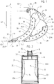
- This bucket 10 shown on Figures 1 and 2 , comprises a bottom 11 terminated at a first end 12 by a cutting edge 13 and laterally extended by two substantially vertical flanks 14, 15.
- the bottom 11 and the flanks 14, 15 are made of a metal material for example a metal sheet thickness of 5 to 10mm. These flanks 14, 15 are for example welded, at their rear connecting edge 16 at the bottom 11.
- a fixing means 18 of the bucket 10 is fixed, for example welded, a fixing means 18 of the bucket 10 to a shovel.
- This means of fastener 18, generally in the form of hooks is of course a function of the excavator on which the bucket 10 is to be mounted.
- fastening means 18 usually define a pivot axis 19 of the bucket 10 with respect to this excavator. This pivot axis 19 is substantially parallel to the cutting edge 13 of the bottom 11.
- the bucket 10 according to the invention is characterized in that an outer wall 20 of the bottom 11 at least in the vicinity of the cutting edge 13 and an outer wall 21 of the flanks 14, 15, at least in the vicinity of the joining edge 16 with the bottom 11 and in the vicinity of the free edge 22, 23 of the sides 14, 15, are covered with a layer 24, 25, 26, 27 of a synthetic material.
- free edge 22, 23 of a flank 14, 15 is meant, of course, the edge opposite the rear junction edge 16.
- a layer of synthetic material 24 to 27 is defined in the form of a plate, preferably made of polyurethane.
- This plate 24 to 27 has a thickness greater than 20 mm, preferably of the order of 30 mm.
- Said layers 24 to 27 in the form of plates can be screwed by screw-nut systems 28 on the bottom 11 and the metal flanks 14, 15 of the cup 10.
- Recesses, in the form of counterbore in the plates 24 to 27, allow a depressing the screw heads, preferably flat, so that they do not move on the surface of said plates 24 to 27.
- stoppers 29 may be formed against which said plates 24 to 27 may immobilize them in position, especially in the working phase of the bucket 10.
- a first plate 24 covers the outer wall 20 of the bottom 11 in the vicinity of the cutting edge 13.
- a second plate 25 covers the outer wall 21 of the sidewall 14 in the vicinity of the free edge 22 of the latter.
- a third plate 26 covers the outer wall 21 of the flank 15 in the vicinity of the free edge 23 of this latest.
- a fourth plate 27 covers the outer wall 21 of the flank 14 in the vicinity of the junction edge 16.
- a fifth plate (not visible in the figures) covers the outer wall 21 of the flank 15, again in the vicinity of the junction edge 16.
- a plate defining a layer of synthetic material 24 to 27 extends from a protruding edge 30 to 33 of about 50 to 300 mm on the outer wall 20; 21 depending on the case of the bottom 11 or flanks 14, 15.
- this layer of synthetic material 24 to 27 extends, forming a protruding flange 24A to 27A, beyond a projecting edge 30 to 33 of the cutting edge 12, the joining edge 16 and / or free edge 22, 23.
- the synthetic material layer 25 to 27 overlaps the free edge 22, 23 and / or the joining edge 16 of the flanks 14, 15 over the entire length of these free edges. 22, 23 and / or junction 16
- said layers of synthetic material 24 to 27 in the form of plates are subject to wear.
- At least one plate 24 to 27 is subdivided into plate sections so as to allow partial replacement of the latter. This subdivision may be provided, as the case may be, parallel or perpendicular to a projecting edge 30 to 33 of the bucket 10.
- the plate 24 coming to cover the cutting edge 13 of the bottom 11 may be subdivided into sections parallel to the projecting edge 30 of this cutting edge 13.
- the plates 25, 26, 27, covering the free edge 22, 23 and the junction edge 16 of the flanks 14 and 15, can be subdivided into sections in a direction perpendicular to the projecting edges 30 to 33 defined by these edges 22, 23, 16.
- similar protective means in the form of a layer of synthetic material 35, 36, are associated with the fastening means 18 over the bucket 10.
- the fixing means 18 are generally in the form of hooks
- the layer of synthetic material 35, 36 may, again, be in the form of a plate that overlaps tabs 37, 38 corresponding to such hooks 19 .
- a bucket 10 according to the invention can be completely covered, at the level of the outer wall 20 of the bottom 11 and / or at the level of the outer wall 21 of the sidewalls 14, 15, by a layer of synthetic material, especially in the form of a plate.
- the layer of synthetic material may be overmolded on the cutting edge 13 so as to cover the latter and the inner and outer walls 20 of the bottom 11 in the vicinity of the cutting edge 13 and / or the layer of material synthetic material can be overmolded on the free edge 22, 23 of a flank 14, 15 so as to cover the inner and outer walls 21 of this sidewall 14, 15 in the vicinity of said free edge 22, 23 and / or the layer of synthetic material may be overmolded on the rear junction edge 16 of a flank 14, 15 so as to cover the outer wall 21 of the sidewalls 14, 15 and the outer wall 20 of the bottom 11 in the vicinity of this free edge 16.
- the free edges 22, 23 of the flanks 14, 15 are of curvilinear shape with a radius of curvature 39 substantially proportional to the section of the pipe to be released.
- the distance 40 separating the plane 41 perpendicular to the edge 30 at the edge cutting edge 13 of the bottom 11 and the pivot axis 19 of the attachment means 18 of the bucket 10 and / or the distance 42 separating the plane 43 corresponding to this cutting edge 13 relative to this pivot axis 19 of the fastening means 18 of the bucket 10 is, respectively, are defined, substantially proportional to the section of the pipe to clear.
- the distance 40 is preferably between 450mm and 570mm, preferably of the order of 520mm for a pipe diameter of between 80mm and 300mm and between 950mm and 12500mm, preferably of the order of 1100mm for a diameter. driving range between 650mm and 1200mm.
- the distance 42 it is, preferably, between 600 mm and 800 mm, preferably of the order of 700 mm for a driving diameter of between 80 mm and 300 mm and between 1200 mm and 1800 mm, preferably of the order of 1500 mm for a pipe diameter of between 650mm and 1200mm.
Landscapes
- Engineering & Computer Science (AREA)
- Mechanical Engineering (AREA)
- Mining & Mineral Resources (AREA)
- Civil Engineering (AREA)
- General Engineering & Computer Science (AREA)
- Structural Engineering (AREA)
- Shovels (AREA)
Claims (11)
- Löffel für Löffelbagger, umfassend einen Boden (11), der an einem Ende (12) in einer Schneidkante (13) endet und seitlich von zwei etwa vertikalen Flanken (14, 5) verlängert wird, aufweisend einen Verbindungsrand (16) mit dem Boden (11) und einen freien Rand (22, 23), wobei der Boden (11) und die Flanke (14, 15) aus einem metallischen Material hergestellt sind, wobei dieser Löffel noch eine Schicht aus synthetischem Material (24, 25, 26, 27) aufweist, die auf einer Außenwand (20) des Bodens (11) mindestens in der Nähe der Schneidkante (13) und auf einer Außenwand (21) der Flanken (14, 15) mindestens in der Nähe des Verbindungsrands (16) mit dem Boden (11) und des freien Rands (22, 23) anliegt, wobei sich diese Schicht aus synthetischem Material (24, 25, 26, 27), indem sie eine über vorspringende Grate (30, 31, 32, 33) der Schneidkante (13), des Verbindungsrands (16) und des freien Rands (22, 23) vorspringende Kante (24A, 25A, 26A, 27A) bildet, erstreckt, dadurch gekennzeichnet, dass die freien Ränder (22, 23) der Flanken (14, 15) mit einem Krümmungsradius (39), der proportional zum Querschnitt der freizumachenden Führung ist, gekrümmt geformt sind.
- Löffel nach Anspruch 1, dadurch gekennzeichnet, dass sich eine Schicht aus synthetischem Material (24 bis 27) ab einem vorspringenden Grat (30 bis 33) über zirka 50 bis 300 mm über die Außenwand (20, 21), je nach Fall, des Bodens (11) oder der Flanken (14, 15) erstreckt.
- Löffel nach einem der vorangehenden Ansprüche, dadurch gekennzeichnet, dass sich eine Schicht aus synthetischem Material (24 bis 27), indem sie eine vorspringende Kante (24A bis 27A) bildet, über einen vorspringenden Grat (30 bis 33) der Schneidkante (12), des Verbindungsrands (16) und/oder des freien Rands (22, 23) über einen Abstand von 5 bis 100 mm erstreckt.
- Löffel nach einem der vorangehenden Ansprüche, dadurch gekennzeichnet, dass die Schicht aus synthetischem Material (25 bis 27) den freien Rand (22, 23) und/oder den Verbindungsrand (16) der Flanken (14, 15) über die gesamte Länge eines freien Rands (22, 23) und/oder eines Verbindungsrands (16) bedeckt.
- Löffel nach einem der vorangehenden Ansprüche, dadurch gekennzeichnet, dass eine Schicht aus synthetischem Material (24 bis 27) von einer Platte definiert ist.
- Löffel nach Anspruch 5, dadurch gekennzeichnet, dass eine Schicht aus synthetischem Material (25 bis 27) in Form einer Platte mit Schraube-Mutter-Systemen (28) auf dem Boden (11) oder einer Flanke (14, 15) befestigt ist.
- Löffel nach einem der Ansprüche 5 und 6, dadurch gekennzeichnet, dass eine Platte, die eine Schicht aus synthetischem Material (24 bis 27) definiert, in Plattenabschnitte unterteilt ist.
- Löffel nach einem der Ansprüche 1 bis 4, dadurch gekennzeichnet, dass die Schicht aus synthetischem Material derart auf der Schneidkante (13) aufgeformt ist, dass diese und die Innen- und Außenwand (20) des Bodens (11) mindestens in der Nähe der Schneidkante (13) und/oder auf dem freien Rand (22, 23) einer Flanke (14, 15) derart bedecken, dass die Innen- und Außenwand (21) der Flanke (14, 15) in der Nähe des freien Rands (22, 23) und/oder auf dem hinteren Verbindungsrand (16) einer Flanke (14, 15) bedeckt sind, um die Außenwand (21) dieser Flanke (14, 15) und die Außenwand (20) des Bodens (11) in der Nähe dieses freien Rands (16) zu bedecken.
- Löffel nach einem der vorangehenden Ansprüche, dadurch gekennzeichnet, dass eine Schicht aus synthetischem Material die Außenwand (20) des Bodens (11) und/oder die Außenwand (21) der Flanken (14, 15) vollständig bedeckt.
- Löffel nach einem der vorangehenden Ansprüche, dadurch gekennzeichnet, dass der Abstand (40), der die Ebene (41) senkrecht zum Grat (30) an der Schneidkante (13) des Bodens (11) von der Schwenkachse (19) des Befestigungsmittels (18) des Löffels (10) und/oder der Abstand (42), der die dieser Schneidkante (13) entsprechende Ebene (43) in Bezug auf diese Schwenkachse (19) des Befestigungsmittels (18) des Löffels (10) trennt, etwa proportional zum Querschnitt der freizumachenden Führung definiert ist beziehungsweise sind.
- Löffel nach einem der vorangehenden Ansprüche, dadurch gekennzeichnet, dass den Befestigungsmitteln (18), die über den Löffel (10) vorspringen, Schutzeinrichtungen in Form einer Schicht aus synthetischem Material (35, 36) zugeordnet sind.
Applications Claiming Priority (1)
| Application Number | Priority Date | Filing Date | Title |
|---|---|---|---|
| FR1252096A FR2987850B1 (fr) | 2012-03-08 | 2012-03-08 | Godet pour pelle mecanique |
Publications (2)
| Publication Number | Publication Date |
|---|---|
| EP2636801A1 EP2636801A1 (de) | 2013-09-11 |
| EP2636801B1 true EP2636801B1 (de) | 2018-08-01 |
Family
ID=47790105
Family Applications (1)
| Application Number | Title | Priority Date | Filing Date |
|---|---|---|---|
| EP13158405.4A Active EP2636801B1 (de) | 2012-03-08 | 2013-03-08 | Löffel eines Löffelbaggers |
Country Status (2)
| Country | Link |
|---|---|
| EP (1) | EP2636801B1 (de) |
| FR (1) | FR2987850B1 (de) |
Families Citing this family (2)
| Publication number | Priority date | Publication date | Assignee | Title |
|---|---|---|---|---|
| CN104775460B (zh) * | 2015-02-12 | 2017-07-28 | 龙岩市海博工程机械有限公司 | 一种挖掘机挖斗耐磨改良结构 |
| CN107989100B (zh) * | 2017-11-14 | 2023-08-08 | 中电建生态环境集团有限公司 | 生态清淤设备属具 |
Family Cites Families (6)
| Publication number | Priority date | Publication date | Assignee | Title |
|---|---|---|---|---|
| US4905386A (en) * | 1988-09-02 | 1990-03-06 | The Dow Chemical Company | Process for unearthing hazardous pipeline |
| JP3030396B2 (ja) * | 1997-11-04 | 2000-04-10 | 克紀 棚田 | 掘削機におけるバケット等の作業具の作動装置 |
| JP3397679B2 (ja) * | 1998-02-19 | 2003-04-21 | 関門港湾建設株式会社 | バケット |
| GB2347921A (en) * | 1999-03-17 | 2000-09-20 | Lee Shearsby Dodd Ltd | Excavator tool with cutting elements arranged on a convex surface |
| SE525518C2 (sv) * | 2002-03-18 | 2005-03-01 | Ulf Hedberg | Balkförstärkning på grävskopa |
| US7797861B2 (en) * | 2006-08-14 | 2010-09-21 | Wright Danny M | Resilient excavation bucket, excavation apparatus, and methods of use and manufacture thereof |
-
2012
- 2012-03-08 FR FR1252096A patent/FR2987850B1/fr not_active Expired - Fee Related
-
2013
- 2013-03-08 EP EP13158405.4A patent/EP2636801B1/de active Active
Also Published As
| Publication number | Publication date |
|---|---|
| FR2987850A1 (fr) | 2013-09-13 |
| FR2987850B1 (fr) | 2014-12-26 |
| EP2636801A1 (de) | 2013-09-11 |
Similar Documents
| Publication | Publication Date | Title |
|---|---|---|
| EP2780178B1 (de) | Vorrichtung zur resonanzrauschunterdrückung für reifen | |
| EP2636801B1 (de) | Löffel eines Löffelbaggers | |
| EP3230090B1 (de) | Vorrichtung zur dämpfung des fahrbahngeräusches für einen reifen | |
| FR3097805A1 (fr) | protection de différentiel d’essieu | |
| FR2952900A1 (fr) | Cle extractible pour joint de vitrage et procede d'extraction s'y rapportant | |
| WO2016188640A1 (fr) | Couverture amovible destinée à être disposée en regard d'une conduite de transport de fluide immergée dans une étendue d'eau, ensemble d'intervention et procédé associés | |
| FR3025164A1 (fr) | Systeme d'etancheite pour un ouvrant comportant un profile recevant un joint d'etancheite verrouille par une cle coulissante | |
| EP2473683B1 (de) | Vorrichtung für abdeckung und schutz von erdverlegten rohren oder kabeln | |
| EP3317164B1 (de) | Kraftfahrzeug mit einem kotflügel mit einer rinne | |
| EP3167129B1 (de) | Vorrichtung zur installation von boden- und wandbelägen in projektionsecken | |
| FR3099083A1 (fr) | Plaque de garde de différentiel d’essieu | |
| FR2939158A1 (fr) | Regard enterre modulaire | |
| EP0794347A1 (de) | Schutzfaltenbalg für einen Antrieb | |
| EP2754623A1 (de) | Gesicherte Zisterne für die Lagerung von flüssigen chemischen Produkten | |
| EP2902555B1 (de) | Anschlussteil von einer Regenwasserkanalisationsleitung, Sichtschacht für Regenwasserkanalisationsleitungen, und gesamte Kanalisationsleitung, die einen solchen Sichtschacht umfasst | |
| EP3592600B1 (de) | Fussstütze mit integrierter verstärkungsstruktur | |
| FR2697094A1 (fr) | Dispositif avertisseur pour le repérage de canalisations ou câbles enterrés. | |
| EP3735504B1 (de) | Verbesserung an einem deflektor zum schutz der füsse einer struktur | |
| FR2924197A1 (fr) | Dispositif de recouvrement et de protection de conduites ou cables enterres | |
| FR2962512A1 (fr) | Dispositif d'avertissement et de protection de conduites ou cables enterres | |
| FR3052225A1 (fr) | Piece de raccord, pour le raccordement d'une conduite de descente de gouttiere a une conduite d'evacuation et procede de raccordement correspondant | |
| WO2012004479A1 (fr) | Dispositif de protection d'embout mâle de tuyauterie | |
| EP3462072B1 (de) | Verbindungsvorrichtung eines rohrs und eines zugangsschacht | |
| FR3060621A1 (fr) | Regard avaloir a tubulure coudee | |
| WO2025061770A1 (fr) | Ensemble de conditionnement pour une paire de balais d'essuie-glace |
Legal Events
| Date | Code | Title | Description |
|---|---|---|---|
| PUAI | Public reference made under article 153(3) epc to a published international application that has entered the european phase |
Free format text: ORIGINAL CODE: 0009012 |
|
| AK | Designated contracting states |
Kind code of ref document: A1 Designated state(s): AL AT BE BG CH CY CZ DE DK EE ES FI FR GB GR HR HU IE IS IT LI LT LU LV MC MK MT NL NO PL PT RO RS SE SI SK SM TR |
|
| AX | Request for extension of the european patent |
Extension state: BA ME |
|
| 17P | Request for examination filed |
Effective date: 20140307 |
|
| RBV | Designated contracting states (corrected) |
Designated state(s): AL AT BE BG CH CY CZ DE DK EE ES FI FR GB GR HR HU IE IS IT LI LT LU LV MC MK MT NL NO PL PT RO RS SE SI SK SM TR |
|
| GRAP | Despatch of communication of intention to grant a patent |
Free format text: ORIGINAL CODE: EPIDOSNIGR1 |
|
| STAA | Information on the status of an ep patent application or granted ep patent |
Free format text: STATUS: GRANT OF PATENT IS INTENDED |
|
| INTG | Intention to grant announced |
Effective date: 20180301 |
|
| GRAS | Grant fee paid |
Free format text: ORIGINAL CODE: EPIDOSNIGR3 |
|
| GRAA | (expected) grant |
Free format text: ORIGINAL CODE: 0009210 |
|
| STAA | Information on the status of an ep patent application or granted ep patent |
Free format text: STATUS: THE PATENT HAS BEEN GRANTED |
|
| AK | Designated contracting states |
Kind code of ref document: B1 Designated state(s): AL AT BE BG CH CY CZ DE DK EE ES FI FR GB GR HR HU IE IS IT LI LT LU LV MC MK MT NL NO PL PT RO RS SE SI SK SM TR |
|
| REG | Reference to a national code |
Ref country code: GB Ref legal event code: FG4D Free format text: NOT ENGLISH |
|
| REG | Reference to a national code |
Ref country code: CH Ref legal event code: EP Ref country code: AT Ref legal event code: REF Ref document number: 1024466 Country of ref document: AT Kind code of ref document: T Effective date: 20180815 |
|
| REG | Reference to a national code |
Ref country code: IE Ref legal event code: FG4D Free format text: LANGUAGE OF EP DOCUMENT: FRENCH |
|
| REG | Reference to a national code |
Ref country code: DE Ref legal event code: R096 Ref document number: 602013041054 Country of ref document: DE |
|
| REG | Reference to a national code |
Ref country code: NL Ref legal event code: MP Effective date: 20180801 |
|
| REG | Reference to a national code |
Ref country code: LT Ref legal event code: MG4D |
|
| REG | Reference to a national code |
Ref country code: AT Ref legal event code: MK05 Ref document number: 1024466 Country of ref document: AT Kind code of ref document: T Effective date: 20180801 |
|
| PG25 | Lapsed in a contracting state [announced via postgrant information from national office to epo] |
Ref country code: GR Free format text: LAPSE BECAUSE OF FAILURE TO SUBMIT A TRANSLATION OF THE DESCRIPTION OR TO PAY THE FEE WITHIN THE PRESCRIBED TIME-LIMIT Effective date: 20181102 Ref country code: SE Free format text: LAPSE BECAUSE OF FAILURE TO SUBMIT A TRANSLATION OF THE DESCRIPTION OR TO PAY THE FEE WITHIN THE PRESCRIBED TIME-LIMIT Effective date: 20180801 Ref country code: BG Free format text: LAPSE BECAUSE OF FAILURE TO SUBMIT A TRANSLATION OF THE DESCRIPTION OR TO PAY THE FEE WITHIN THE PRESCRIBED TIME-LIMIT Effective date: 20181101 Ref country code: NO Free format text: LAPSE BECAUSE OF FAILURE TO SUBMIT A TRANSLATION OF THE DESCRIPTION OR TO PAY THE FEE WITHIN THE PRESCRIBED TIME-LIMIT Effective date: 20181101 Ref country code: RS Free format text: LAPSE BECAUSE OF FAILURE TO SUBMIT A TRANSLATION OF THE DESCRIPTION OR TO PAY THE FEE WITHIN THE PRESCRIBED TIME-LIMIT Effective date: 20180801 Ref country code: NL Free format text: LAPSE BECAUSE OF FAILURE TO SUBMIT A TRANSLATION OF THE DESCRIPTION OR TO PAY THE FEE WITHIN THE PRESCRIBED TIME-LIMIT Effective date: 20180801 Ref country code: LT Free format text: LAPSE BECAUSE OF FAILURE TO SUBMIT A TRANSLATION OF THE DESCRIPTION OR TO PAY THE FEE WITHIN THE PRESCRIBED TIME-LIMIT Effective date: 20180801 Ref country code: PL Free format text: LAPSE BECAUSE OF FAILURE TO SUBMIT A TRANSLATION OF THE DESCRIPTION OR TO PAY THE FEE WITHIN THE PRESCRIBED TIME-LIMIT Effective date: 20180801 Ref country code: FI Free format text: LAPSE BECAUSE OF FAILURE TO SUBMIT A TRANSLATION OF THE DESCRIPTION OR TO PAY THE FEE WITHIN THE PRESCRIBED TIME-LIMIT Effective date: 20180801 Ref country code: IS Free format text: LAPSE BECAUSE OF FAILURE TO SUBMIT A TRANSLATION OF THE DESCRIPTION OR TO PAY THE FEE WITHIN THE PRESCRIBED TIME-LIMIT Effective date: 20181201 Ref country code: AT Free format text: LAPSE BECAUSE OF FAILURE TO SUBMIT A TRANSLATION OF THE DESCRIPTION OR TO PAY THE FEE WITHIN THE PRESCRIBED TIME-LIMIT Effective date: 20180801 |
|
| PG25 | Lapsed in a contracting state [announced via postgrant information from national office to epo] |
Ref country code: AL Free format text: LAPSE BECAUSE OF FAILURE TO SUBMIT A TRANSLATION OF THE DESCRIPTION OR TO PAY THE FEE WITHIN THE PRESCRIBED TIME-LIMIT Effective date: 20180801 Ref country code: LV Free format text: LAPSE BECAUSE OF FAILURE TO SUBMIT A TRANSLATION OF THE DESCRIPTION OR TO PAY THE FEE WITHIN THE PRESCRIBED TIME-LIMIT Effective date: 20180801 Ref country code: HR Free format text: LAPSE BECAUSE OF FAILURE TO SUBMIT A TRANSLATION OF THE DESCRIPTION OR TO PAY THE FEE WITHIN THE PRESCRIBED TIME-LIMIT Effective date: 20180801 |
|
| PG25 | Lapsed in a contracting state [announced via postgrant information from national office to epo] |
Ref country code: IT Free format text: LAPSE BECAUSE OF FAILURE TO SUBMIT A TRANSLATION OF THE DESCRIPTION OR TO PAY THE FEE WITHIN THE PRESCRIBED TIME-LIMIT Effective date: 20180801 Ref country code: EE Free format text: LAPSE BECAUSE OF FAILURE TO SUBMIT A TRANSLATION OF THE DESCRIPTION OR TO PAY THE FEE WITHIN THE PRESCRIBED TIME-LIMIT Effective date: 20180801 Ref country code: CZ Free format text: LAPSE BECAUSE OF FAILURE TO SUBMIT A TRANSLATION OF THE DESCRIPTION OR TO PAY THE FEE WITHIN THE PRESCRIBED TIME-LIMIT Effective date: 20180801 Ref country code: RO Free format text: LAPSE BECAUSE OF FAILURE TO SUBMIT A TRANSLATION OF THE DESCRIPTION OR TO PAY THE FEE WITHIN THE PRESCRIBED TIME-LIMIT Effective date: 20180801 Ref country code: ES Free format text: LAPSE BECAUSE OF FAILURE TO SUBMIT A TRANSLATION OF THE DESCRIPTION OR TO PAY THE FEE WITHIN THE PRESCRIBED TIME-LIMIT Effective date: 20180801 |
|
| REG | Reference to a national code |
Ref country code: DE Ref legal event code: R097 Ref document number: 602013041054 Country of ref document: DE |
|
| PG25 | Lapsed in a contracting state [announced via postgrant information from national office to epo] |
Ref country code: SK Free format text: LAPSE BECAUSE OF FAILURE TO SUBMIT A TRANSLATION OF THE DESCRIPTION OR TO PAY THE FEE WITHIN THE PRESCRIBED TIME-LIMIT Effective date: 20180801 Ref country code: DK Free format text: LAPSE BECAUSE OF FAILURE TO SUBMIT A TRANSLATION OF THE DESCRIPTION OR TO PAY THE FEE WITHIN THE PRESCRIBED TIME-LIMIT Effective date: 20180801 Ref country code: SM Free format text: LAPSE BECAUSE OF FAILURE TO SUBMIT A TRANSLATION OF THE DESCRIPTION OR TO PAY THE FEE WITHIN THE PRESCRIBED TIME-LIMIT Effective date: 20180801 |
|
| PLBE | No opposition filed within time limit |
Free format text: ORIGINAL CODE: 0009261 |
|
| STAA | Information on the status of an ep patent application or granted ep patent |
Free format text: STATUS: NO OPPOSITION FILED WITHIN TIME LIMIT |
|
| 26N | No opposition filed |
Effective date: 20190503 |
|
| PG25 | Lapsed in a contracting state [announced via postgrant information from national office to epo] |
Ref country code: SI Free format text: LAPSE BECAUSE OF FAILURE TO SUBMIT A TRANSLATION OF THE DESCRIPTION OR TO PAY THE FEE WITHIN THE PRESCRIBED TIME-LIMIT Effective date: 20180801 |
|
| PG25 | Lapsed in a contracting state [announced via postgrant information from national office to epo] |
Ref country code: MC Free format text: LAPSE BECAUSE OF FAILURE TO SUBMIT A TRANSLATION OF THE DESCRIPTION OR TO PAY THE FEE WITHIN THE PRESCRIBED TIME-LIMIT Effective date: 20180801 |
|
| PGFP | Annual fee paid to national office [announced via postgrant information from national office to epo] |
Ref country code: DE Payment date: 20190828 Year of fee payment: 7 |
|
| REG | Reference to a national code |
Ref country code: CH Ref legal event code: PL |
|
| GBPC | Gb: european patent ceased through non-payment of renewal fee |
Effective date: 20190308 |
|
| PG25 | Lapsed in a contracting state [announced via postgrant information from national office to epo] |
Ref country code: LU Free format text: LAPSE BECAUSE OF NON-PAYMENT OF DUE FEES Effective date: 20190308 |
|
| REG | Reference to a national code |
Ref country code: BE Ref legal event code: MM Effective date: 20190331 |
|
| PG25 | Lapsed in a contracting state [announced via postgrant information from national office to epo] |
Ref country code: LI Free format text: LAPSE BECAUSE OF NON-PAYMENT OF DUE FEES Effective date: 20190331 Ref country code: CH Free format text: LAPSE BECAUSE OF NON-PAYMENT OF DUE FEES Effective date: 20190331 Ref country code: IE Free format text: LAPSE BECAUSE OF NON-PAYMENT OF DUE FEES Effective date: 20190308 Ref country code: GB Free format text: LAPSE BECAUSE OF NON-PAYMENT OF DUE FEES Effective date: 20190308 |
|
| PG25 | Lapsed in a contracting state [announced via postgrant information from national office to epo] |
Ref country code: BE Free format text: LAPSE BECAUSE OF NON-PAYMENT OF DUE FEES Effective date: 20190331 |
|
| PG25 | Lapsed in a contracting state [announced via postgrant information from national office to epo] |
Ref country code: TR Free format text: LAPSE BECAUSE OF FAILURE TO SUBMIT A TRANSLATION OF THE DESCRIPTION OR TO PAY THE FEE WITHIN THE PRESCRIBED TIME-LIMIT Effective date: 20180801 |
|
| PG25 | Lapsed in a contracting state [announced via postgrant information from national office to epo] |
Ref country code: PT Free format text: LAPSE BECAUSE OF FAILURE TO SUBMIT A TRANSLATION OF THE DESCRIPTION OR TO PAY THE FEE WITHIN THE PRESCRIBED TIME-LIMIT Effective date: 20181201 Ref country code: MT Free format text: LAPSE BECAUSE OF FAILURE TO SUBMIT A TRANSLATION OF THE DESCRIPTION OR TO PAY THE FEE WITHIN THE PRESCRIBED TIME-LIMIT Effective date: 20180801 |
|
| REG | Reference to a national code |
Ref country code: DE Ref legal event code: R119 Ref document number: 602013041054 Country of ref document: DE |
|
| PG25 | Lapsed in a contracting state [announced via postgrant information from national office to epo] |
Ref country code: DE Free format text: LAPSE BECAUSE OF NON-PAYMENT OF DUE FEES Effective date: 20201001 |
|
| PG25 | Lapsed in a contracting state [announced via postgrant information from national office to epo] |
Ref country code: CY Free format text: LAPSE BECAUSE OF FAILURE TO SUBMIT A TRANSLATION OF THE DESCRIPTION OR TO PAY THE FEE WITHIN THE PRESCRIBED TIME-LIMIT Effective date: 20180801 |
|
| PG25 | Lapsed in a contracting state [announced via postgrant information from national office to epo] |
Ref country code: HU Free format text: LAPSE BECAUSE OF FAILURE TO SUBMIT A TRANSLATION OF THE DESCRIPTION OR TO PAY THE FEE WITHIN THE PRESCRIBED TIME-LIMIT; INVALID AB INITIO Effective date: 20130308 |
|
| PG25 | Lapsed in a contracting state [announced via postgrant information from national office to epo] |
Ref country code: MK Free format text: LAPSE BECAUSE OF FAILURE TO SUBMIT A TRANSLATION OF THE DESCRIPTION OR TO PAY THE FEE WITHIN THE PRESCRIBED TIME-LIMIT Effective date: 20180801 |
|
| PGFP | Annual fee paid to national office [announced via postgrant information from national office to epo] |
Ref country code: FR Payment date: 20260312 Year of fee payment: 14 |