EP3730218B1 - Dispersion plate and coating device including it - Google Patents
Dispersion plate and coating device including it Download PDFInfo
- Publication number
- EP3730218B1 EP3730218B1 EP19851149.5A EP19851149A EP3730218B1 EP 3730218 B1 EP3730218 B1 EP 3730218B1 EP 19851149 A EP19851149 A EP 19851149A EP 3730218 B1 EP3730218 B1 EP 3730218B1
- Authority
- EP
- European Patent Office
- Prior art keywords
- region
- dispersion plate
- chamber
- opening ratio
- diameter
- Prior art date
- Legal status (The legal status is an assumption and is not a legal conclusion. Google has not performed a legal analysis and makes no representation as to the accuracy of the status listed.)
- Active
Links
Images


Classifications
-
- B—PERFORMING OPERATIONS; TRANSPORTING
- B01—PHYSICAL OR CHEMICAL PROCESSES OR APPARATUS IN GENERAL
- B01J—CHEMICAL OR PHYSICAL PROCESSES, e.g. CATALYSIS OR COLLOID CHEMISTRY; THEIR RELEVANT APPARATUS
- B01J19/00—Chemical, physical or physico-chemical processes in general; Their relevant apparatus
- B01J19/0053—Details of the reactor
- B01J19/006—Baffles
-
- B—PERFORMING OPERATIONS; TRANSPORTING
- B01—PHYSICAL OR CHEMICAL PROCESSES OR APPARATUS IN GENERAL
- B01J—CHEMICAL OR PHYSICAL PROCESSES, e.g. CATALYSIS OR COLLOID CHEMISTRY; THEIR RELEVANT APPARATUS
- B01J2/00—Processes or devices for granulating materials, e.g. fertilisers in general; Rendering particulate materials free flowing in general, e.g. making them hydrophobic
- B01J2/006—Coating of the granules without description of the process or the device by which the granules are obtained
-
- B—PERFORMING OPERATIONS; TRANSPORTING
- B01—PHYSICAL OR CHEMICAL PROCESSES OR APPARATUS IN GENERAL
- B01J—CHEMICAL OR PHYSICAL PROCESSES, e.g. CATALYSIS OR COLLOID CHEMISTRY; THEIR RELEVANT APPARATUS
- B01J2/00—Processes or devices for granulating materials, e.g. fertilisers in general; Rendering particulate materials free flowing in general, e.g. making them hydrophobic
- B01J2/16—Processes or devices for granulating materials, e.g. fertilisers in general; Rendering particulate materials free flowing in general, e.g. making them hydrophobic by suspending the powder material in a gas, e.g. in fluidised beds or as a falling curtain
-
- B—PERFORMING OPERATIONS; TRANSPORTING
- B01—PHYSICAL OR CHEMICAL PROCESSES OR APPARATUS IN GENERAL
- B01J—CHEMICAL OR PHYSICAL PROCESSES, e.g. CATALYSIS OR COLLOID CHEMISTRY; THEIR RELEVANT APPARATUS
- B01J8/00—Chemical or physical processes in general, conducted in the presence of fluids and solid particles; Apparatus for such processes
- B01J8/18—Chemical or physical processes in general, conducted in the presence of fluids and solid particles; Apparatus for such processes with fluidised particles
- B01J8/24—Chemical or physical processes in general, conducted in the presence of fluids and solid particles; Apparatus for such processes with fluidised particles according to "fluidised-bed" technique
- B01J8/44—Fluidisation grids
-
- B—PERFORMING OPERATIONS; TRANSPORTING
- B01—PHYSICAL OR CHEMICAL PROCESSES OR APPARATUS IN GENERAL
- B01J—CHEMICAL OR PHYSICAL PROCESSES, e.g. CATALYSIS OR COLLOID CHEMISTRY; THEIR RELEVANT APPARATUS
- B01J2219/00—Chemical, physical or physico-chemical processes in general; Their relevant apparatus
- B01J2219/00761—Details of the reactor
- B01J2219/00763—Baffles
Definitions
- the present invention relates to a dispersion plate and a coating device comprising the same, and particularly, relates to a dispersion plate used in a fluidized bed coating device and a fluidized bed coating device comprising the same.
- a fluidized bed coating device is a device that sprays gas from a dispersion plate to coat fluidized particles with a polymer solution or the like and dries them.
- the dispersion plate is perforated with gas injection holes to prevent particle retention, and comprises spout nozzles disposed at certain portions of the dispersion plate. Relatively large holes are clustered in each spout nozzle.
- Spout regions with a low particle ratio in a bed are formed by the gas injection of the spout nozzles, and the coating of the particles is performed by a polymer droplet injection nozzle located therein.
- the coated particles are ejected to the top of the bed and then dried while descending.
- the particle flow in the spout regions is smooth, so that there should be no coating interference phenomenon between particles.
- the pitch (interval) of the gas injection holes is widened, so that there is a possibility of generating particle flow dead zones and there is a possibility of occurrence of a particle falling-out phenomenon by the widened holes. Therefore, the size of holes must be smaller than the size of particles to be produced.
- the present invention provides a dispersion plate as defined in claim 1, comprising: a plurality of gas injection holes over the entire region of the dispersion plate, wherein the plurality of gas injection holes are positioned in the dispersion plate such that a plurality of spout nozzles are formed by dense groupings of the gas injection holes, wherein the spout nozzle means a region of the dispersion plate in which the density of the gas injection holes is higher than that of the other region of the dispersion plate except for the spout nozzle, wherein one of the plurality of spout nozzles is disposed at a center of the dispersion plate, and other ones of the plurality of spout nozzles are arranged along a plurality of virtual concentric circles distributed from the center of the dispersion plate to a peripheral edge of the dispersion plate, and wherein with respect to two adjacent ones of the virtual concentric circles, a number of spout nozzles arranged along an
- a radial distance between respective ones of the virtual concentric circles may be the same, and a circumferential distance between respective ones of the spout nozzles disposed in a same one of the virtual concentric circles may be the same.
- a diameter of each spout nozzle may be 2 to 20% of a diameter of the dispersion plate, and the radial distance between respective ones of the virtual concentric circles may be 5 to 40% of the diameter of the dispersion plate and 50 to 400% of the diameter of the spout nozzles.
- opening ratios of the gas injection holes may be different within each region of the dispersion plate between the virtual concentric circles, wherein opening ratio means a ratio of the area (total area of the gas injection holes) occupied by a number of gas injection holes formed in the relevant regions based on the total area of the relevant regions including the gas injection holes.
- the opening ratio of a first region outside of an outermost concentric circle may be smaller than the opening ratio of a second region adjacent to the first region, the opening ratio of the first region may be smaller than the opening ratio of a third region inside of an innermost concentric circle, and the opening ratio of the second region may be greater than or equal to the opening ratio of the third region.
- the opening ratio of the second region may be 2 to 5 times the opening ratio of the first region
- the opening ratio of the third region may be 1.5 to 4 times the opening ratio of the first region
- the opening ratio of the second region may be 0.5 to 2 times the opening ratio of the third region.
- the present invention provides a coating device comprising a chamber; and the above-described dispersion plate installed inside the chamber.
- the coating device according to the invention may further comprise structures disposed in a wind box portion of the chamber, the structures disposed beneath a bottom of the dispersion plate, the structures being configured to guide a gas flow within the chamber.
- the structures may comprise: a first structure extending across a diameter of the chamber and having a hole at a center thereof, the hole being configured to induce the gas flow toward a center of the chamber; and a second structure disposed concentrically with the first structure and disposed above the first structure, the second structure extending across a central region of the chamber, a peripheral edge of the second structure being spaced apart from a wall of the chamber by a circumferential gap configured to induce the gas flow toward the wall of the chamber.
- the first structure may be disposed in a tapered region of the chamber in which a diameter of the chamber decreases towards a bottom of the chamber, a diameter of the second structure may be 20 to 50% of the diameter of the chamber and 50 to 150% of a diameter of the hole of the first structure, and a radial distance between an inner edge of the first structure and the peripheral edge of the second structure may be 20 to 150% of the diameter of the second structure.
- the coating device according to the present invention may be a fluidized bed coating device that sprays gas from a dispersion plate to coat fluidized particles with a coating liquid and dries them.
- the kind of particles is not particularly limited, which may be, for example, fertilizer particles.
- the size and the input of the particles are not particularly limited, which may be appropriately set.
- the kind of the coating liquid is not particularly limited, which may be, for example, a polymer solution.
- the injection velocity and the coating amount of the coating liquid are not particularly limited, which may be appropriately set.
- the kind of the gas is not specifically limited, and for example, air, hot air, etc. may be used.
- the flow velocity of the gas or the like is not particularly limited, which may be appropriately set.
- the dispersion plate according to the present invention is applicable to other fluidized bed reactors in addition to the coating device.
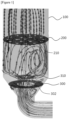
- Figure 1 is a configuration diagram of a coating device according to the present invention, where the coating device may be composed of a chamber (100), a dispersion plate (200), spout nozzles (210), wind box structures (300, 310) and the like.
- the chamber (100) is a coating device body, which may be configured in a cylindrical shape or the like and may comprise a taper region, the diameter of which decreases downward, at the bottom.
- the chamber (100) may be equipped with a particle inlet through which particles to be coated are introduced, a particle outlet through which coated particles are discharged, a gas inlet through which gas is introduced, and a gas outlet through which gas is discharged.
- the size, material, etc. of the chamber (100) are not specifically limited, which may be appropriately set.
- the dispersion plate (200) may be installed throughout the cross-section of the chamber (100) inside the chamber (100), for example, in the horizontal direction.
- the dispersion plate (200) may be composed of a disc.
- the diameter of the dispersion plate (200) may be the same as the inner diameter of the chamber (100).
- the position and the number of the dispersion plates (200) in the chamber are not particularly limited, and for example, one or two or more dispersion plates may be disposed in the lower or middle region of the chamber (100).
- the diameter, thickness, material, and the like of the dispersion plate (200) are not particularly limited, which may be appropriately set.
- the dispersion plate (200) may be mounted or fixed to the chamber (100) by a supporting member, screwing, welding or the like.
- the dispersion plate (200) comprises a plurality of gas injection holes over the entire region of the dispersion plate (200).
- the dispersion plate (200) includes a plurality of spout nozzles (210) formed by a dense arrangement of the gas injection holes. Since the size of the gas injection holes is very fine and the number is also very large, they have been not separately shown or indicated in the drawings.
- the spout nozzle (210) may mean a region of the dispersion plate (200) that may be visually distinguished from the other region of the dispersion plate (200) except for the spout nozzle (210) due to the difference in the density of the gas injection holes.
- the spout nozzle (210) may mean a region of the dispersion plate (200) in which the density of the gas injection holes is higher than that of the other region of the dispersion plate (200) except for the spout nozzle (210).
- the difference in density between two regions (inner region and outer region of spout nozzle) is not particularly limited, which may be appropriately set.
- the gas injection holes may be formed through the dispersion plate (200) in the thickness direction of the dispersion plate (200), and the gas is introduced from the bottom of the dispersion plate (200) and then injected above the dispersion plate (200) while passing through a number of gas injection holes.
- the diameter, number and interval of the gas injection holes are not particularly limited, which may be appropriately set, but the diameter of the gas injection holes should be smaller than the particle diameter.
- the diameter of the gas injection holes formed in the inner region of the spout nozzle (210) is preferably larger than the diameter of the gas injection holes formed in the outer region of the spout nozzle (210), but may also be the same or smaller.
- Figure 2 is a configuration diagram of a dispersion plate according to the present invention, which illustrates the optimum arrangement of the spout nozzles.
- the number of the gas injection holes has been increased by the increased area of the dispersion plate while maintaining their original size, in order to suppress the occurrence of flow dead zones.
- the optimum arrangement of the spout nozzles capable of covering the increased area has been made.
- the concentric circle arrangement has been found to be the best.
- the optimal arrangement of the spout nozzles is a concentric circle arrangement, which is characterized in that one spout nozzle (212) is disposed at the center of the dispersion plate (200), and a plurality of spout nozzles (214, 216) are disposed along a plurality of virtual concentric circles (201, 202) from the center of the dispersion plate (200) to the edge of the dispersion plate (200), where with respect to two adjacent virtual concentric circles (201, 202), the number of the spout nozzles (216) disposed along an outer concentric circle (202) based on the center of the dispersion plate (200) is twice the number of the spout nozzles (214) disposed along an inner concentric circle (201) and the arrangement interval of the spout nozzles (216) disposed along the outer concentric circle (202) is half (that is, 1/2 or 0.5 times) of the arrangement interval of the spout nozzles (214)
- one spout nozzle (212) is disposed at the center of the dispersion plate (200)
- 6 spout nozzles (214) are disposed at intervals of 60 degrees in the first concentric circle (201) near the center of the dispersion plate (200)
- 12 spout nozzles (216) are disposed at intervals of 30 degrees in the second concentric circle (202) positioned outside the first concentric circle (201) and having a larger diameter than that of the first concentric circle (201).
- one spout nozzle (212) is located at the center, 6 spout nozzles (214) are located at intervals of 60 degrees in the next concentric circle (201), and then 12 spout nozzles (216) are located at intervals of 30 degrees in the next concentric circle (202).
- the spout nozzle arrangement begins from one at the center and extends to larger concentric circles.
- the spout nozzles (216) of the outer concentric circle (202) have a characteristic that they are disposed so that the angle is half and the number is doubled, as compared with the arrangement of the spout nozzles (214) of the inner concentric circle (201).
- the particle coating may be smooth by maintaining the independence of each spout region, and it may be advantageous to suppress an agglomeration phenomenon by particle surface stickiness due to the development of the dry region on the particle bed.
- the arrangement of more concentric circles such as a third concentric circle and a fourth concentric circle may be performed according to the sizes of the chamber (100) and the dispersion plate (200).
- 24 spout nozzles may be disposed at intervals of 15 degrees.
- the number of spout nozzles (214) may start with 2 to 5, which is less than 6, or may also start with 7 or more, which is more than 6, or the like, instead of 6.
- the respective concentric circles (201, 202) are arranged concentrically while sharing the center of the dispersion plate (200).
- the interval between the respective concentric circles (201, 202), that is, the radius difference between the respective concentric circles (201, 202) is preferably the same for the respective concentric circles (201, 202), but may also be different.
- the interval between the respective spout nozzles (214, 216) disposed in the same concentric circles (201, 202) is preferably the same, but may also be different.
- the diameters of the respective spout nozzles (212, 214, and 216) are not particularly limited, which may each independently be, for example, 2 to 20%, 5 to 15% or 8 to 12% relative to the diameter of the dispersion plate (200).
- the interval between the respective concentric circles (201, 202) is not particularly limited, which may each independently be, for example, 5 to 40%, 10 to 30% or 15 to 25% relative to the diameter of the dispersion plate (200).
- the interval between the respective concentric circles (201, 202) may each independently be, for example, 50 to 400% (that is, 0.5 to 4 times), 100 to 300% (that is, 1 to 3 times) or 150 to 250% (that is, 1.5 to 2.5 times), relative to the diameter of the spout nozzles (212, 214, and 216).
- the spout nozzles may be provided with atomizers in the form of holes or nozzles capable of spraying the coating liquid.
- One atomizer may be formed in the center of the spout nozzle, and a plurality of atomizers may also be formed in the center region.
- the diameter of the atomizer is preferably larger than the diameter of the gas injection hole, but is not limited thereto.
- one or more gas injection holes formed inside the spout nozzle may also be used as atomizers.
- the coating liquid may be moved and sprayed through a carrier gas (air, etc.).
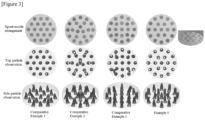
- Figure 3 compares particle observations for each spout nozzle arrangement, which is based on a particle volume ratio of 0.3.
- 19 spout nozzles which are the same as in Example 1, are disposed, and one spout nozzle is disposed at the center of the dispersion plate, but the outermost spout nozzles are not disposed on the concentric circle.
- the opening ratios of the gas injection holes may be different for each region (205, 206, and 207) between the respective concentric circles (201, 202) except for the spout nozzles (212, 214, and 216).
- the opening ratio may mean a ratio of the area (total area of the gas injection holes) occupied by a number of gas injection holes formed in the relevant regions based on the total area of the relevant regions including the gas injection holes.
- the areas of the spout nozzles (212, 214, and 216) may be excluded from the calculation.
- the opening ratio of a first region (205) corresponding to the outer side of the outermost concentric circle (202) may be smaller than the opening ratio of a second region (206) adjacent to the first region (205), and the opening ratio of the first region (205) may be smaller than the opening ratio of a third region (207) corresponding to the inside of the innermost concentric circle (201). That is, the opening ratio of the first region (205) may be the smallest.
- the opening ratio of the second region (206) may be greater than or equal to the opening ratio of the third region (207).
- the number of gas injection holes may be set differently, or the number may be set the same, but the diameter of the gas injection holes may be set differently. That is, the opening ratio may be adjusted by adjusting the number and/or the diameter of the gas injection holes.
- the opening ratio of the second region (206) may be 2 to 5 times or 3 to 4 times the opening ratio of the first region (205), and the opening ratio of the third region (207) may be 1.5 to 4 times or 2 to 3 times the opening ratio of the first region (205), and the opening ratio of the second region (206) may be 0.5 to 2 times or 1 to 1.5 times the opening ratio of the third region (207), without being limited thereto.
- Figure 4 compares particle distribution effects according to opening ratio change for each dispersion plate region, where the region with the greater distance between the spout nozzles can be perforated more largely, thereby suppressing particle aggregation there and improving retention of the particles in the dispersion plate.
- the size of the perforations should not exceed the particle size.
- Example 2 Compared with Example 2, in Examples 3 and 4, the high density particle region was not present or reduced.
- the hole (302) of the first structure (300) may be formed through the first structure (300) in the thickness direction of the first structure (300) in the central region of the first structure (300).
- the hole (302) may be formed in a circular shape and may be formed concentrically with the center of the first structure (300).
- One or a plurality of holes (302) may be formed in the central region.
- the diameter of the hole (302) is not particularly limited, which may be, for example, 20 to 80%, 30 to 70% or 40 to 60% relative to the diameter of the first structure (300).
- a hole may also be formed in the second structure (310).
- the gas flow may be induced not only toward the inner wall of the chamber (100) but also toward the center of the chamber (100).
- the position, shape, number, diameter, and the like of the hole are not particularly limited, which may be appropriately set.
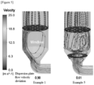
- Example 1 in the case of Example 1 without any wind box structure, the gas flow was deflected toward one side (left) inner wall of the chamber in the wind box region below the dispersion plate, whereby the dispersion plate flow velocity deviation was large as 0.90. Accordingly, the gas flow was uneven even on the top of the dispersion plate.
- Example 5 with the wind box structures, the gas flow in the first structure was induced toward the center of the chamber and then evenly dispersed throughout the entire region of the chamber as it struck the second structure, whereby the flow velocity deviation was significantly reduced as 0.61. Accordingly, the gas flow was uniform even on the top of the dispersion plate.
Landscapes
- Chemical & Material Sciences (AREA)
- Organic Chemistry (AREA)
- Chemical Kinetics & Catalysis (AREA)
- Engineering & Computer Science (AREA)
- Combustion & Propulsion (AREA)
- Nozzles (AREA)
- Glanulating (AREA)
- Devices And Processes Conducted In The Presence Of Fluids And Solid Particles (AREA)
Applications Claiming Priority (2)
| Application Number | Priority Date | Filing Date | Title |
|---|---|---|---|
| KR1020180099107A KR102329735B1 (ko) | 2018-08-24 | 2018-08-24 | 코팅기 |
| PCT/KR2019/010676 WO2020040559A1 (ko) | 2018-08-24 | 2019-08-22 | 분산판 및 이를 포함하는 코팅 장치 |
Publications (3)
| Publication Number | Publication Date |
|---|---|
| EP3730218A1 EP3730218A1 (en) | 2020-10-28 |
| EP3730218A4 EP3730218A4 (en) | 2021-04-07 |
| EP3730218B1 true EP3730218B1 (en) | 2025-07-02 |
Family
ID=69592010
Family Applications (1)
| Application Number | Title | Priority Date | Filing Date |
|---|---|---|---|
| EP19851149.5A Active EP3730218B1 (en) | 2018-08-24 | 2019-08-22 | Dispersion plate and coating device including it |
Country Status (6)
| Country | Link |
|---|---|
| US (1) | US12042776B2 (enExample) |
| EP (1) | EP3730218B1 (enExample) |
| JP (1) | JP7117384B2 (enExample) |
| KR (1) | KR102329735B1 (enExample) |
| CN (1) | CN111565856B (enExample) |
| WO (1) | WO2020040559A1 (enExample) |
Families Citing this family (1)
| Publication number | Priority date | Publication date | Assignee | Title |
|---|---|---|---|---|
| GB202016253D0 (en) * | 2020-10-13 | 2020-11-25 | Ucl Business Plc | Particle processing |
Citations (2)
| Publication number | Priority date | Publication date | Assignee | Title |
|---|---|---|---|---|
| CN101061988A (zh) * | 2006-04-28 | 2007-10-31 | 邹龙贵 | 流化床包衣机 |
| KR101149825B1 (ko) * | 2011-03-11 | 2012-05-24 | 주식회사 영일이엔지 | 균일한 유동층 분포를 가지는 유동층코팅건조기용 다공판 |
Family Cites Families (27)
| Publication number | Priority date | Publication date | Assignee | Title |
|---|---|---|---|---|
| JP2595072Y2 (ja) * | 1992-02-28 | 1999-05-24 | 株式会社大川原製作所 | 流動層処理装置における多孔板ユニット |
| US5328720A (en) * | 1992-10-23 | 1994-07-12 | Carbon Implants, Inc. | Coating-fluidizing gas supply system and method for flat bottom coater |
| FI96867C (fi) * | 1993-12-27 | 1996-09-10 | Borealis Polymers Oy | Leijupetireaktori |
| US5891401A (en) * | 1997-02-05 | 1999-04-06 | Kinetics Technology International Corporation | Porous tuyere for fluid bed apparatus |
| US5904119A (en) * | 1997-06-26 | 1999-05-18 | Brifer International Ltd. | Furnace apparatus for fluidized bed processes |
| CN2351188Y (zh) * | 1997-10-15 | 1999-12-01 | 天津市远昌化工技术开发有限责任公司 | 新型流化造粒炉 |
| US6126753A (en) * | 1998-05-13 | 2000-10-03 | Tokyo Electron Limited | Single-substrate-processing CVD apparatus and method |
| KR100510880B1 (ko) * | 1998-12-18 | 2006-01-27 | 삼성엔지니어링 주식회사 | 분산 노즐 및 이를 이용한 유동층 반응기 |
| US7429407B2 (en) * | 1998-12-30 | 2008-09-30 | Aeromatic Fielder Ag | Process for coating small bodies, including tablets |
| US6247657B1 (en) * | 1999-05-28 | 2001-06-19 | Delphi Technologies, Inc. | Power gun spray nozzle and method |
| JP2003529926A (ja) * | 2000-03-30 | 2003-10-07 | 東京エレクトロン株式会社 | プラズマ処理システム内への調整可能なガス注入のための方法及び装置 |
| EP1282470B1 (en) * | 2000-05-16 | 2008-08-20 | Regents Of The University Of Minnesota | High mass throughput particle generation using multiple nozzle spraying |
| KR100431863B1 (ko) * | 2000-11-16 | 2004-05-20 | 주식회사 포스코 | 유동층 환원로의 분산판 크리닝장치 |
| KR100362684B1 (ko) * | 2000-12-20 | 2002-11-29 | 주식회사 포스코 | 유동층반응로의 분산판 차압조절장치 |
| JP4053379B2 (ja) * | 2002-09-04 | 2008-02-27 | 株式会社パウレック | 流動層装置 |
| CN2649171Y (zh) * | 2003-02-26 | 2004-10-20 | 浙江大学 | 流化床反应装置 |
| CN2708992Y (zh) * | 2004-07-15 | 2005-07-13 | 云南驰宏锌锗股份有限公司 | 一种经济环保型沸腾炉空气分布板 |
| KR101309334B1 (ko) | 2004-08-02 | 2013-09-16 | 비코 인스트루먼츠 인코포레이티드 | 화학적 기상 증착 반응기용 멀티 가스 분배 인젝터 |
| AT503349B1 (de) * | 2005-12-23 | 2008-09-15 | Siemens Vai Metals Tech Gmbh | Verteilerboden |
| KR100847199B1 (ko) * | 2006-01-31 | 2008-07-17 | 주식회사 엘지화학 | 열전달 성능이 향상된 반응기, 이 반응기를 이용한 산화물 제조방법, 및 평행류의 열매체 유속 증가 방법 |
| GB0616131D0 (en) | 2006-08-14 | 2006-09-20 | Oxford Instr Plasma Technology | Surface processing apparatus |
| FI120661B (fi) * | 2008-06-11 | 2010-01-15 | Yit Teollisuus Ja Verkkopalvel | Leijupetikattilan petimateriaalin ohjaussuppilo, leijupetikattila, menetelmä leijupetikattilassa, sisäsuppilo ja sen käyttö |
| KR101134001B1 (ko) | 2008-12-31 | 2012-04-05 | 제일모직주식회사 | 사구역을 최소화하기 위한 유동층 반응기용 송풍구형 분산판 |
| US9427512B2 (en) * | 2012-06-08 | 2016-08-30 | Pall Corporation | Filter device |
| US10071390B2 (en) * | 2012-10-12 | 2018-09-11 | Spraying Systems Co. | Fluidized bed coating apparatus |
| CN204602474U (zh) * | 2015-02-13 | 2015-09-02 | 北京京诚之星科技开发有限公司 | 用于静电粉末喷射装置的压缩空气装置 |
| CN207012954U (zh) * | 2017-07-19 | 2018-02-16 | 南通科恩化工技术有限公司 | 一种气体分布器及有机硅流化床 |
-
2018
- 2018-08-24 KR KR1020180099107A patent/KR102329735B1/ko active Active
-
2019
- 2019-08-22 CN CN201980007640.6A patent/CN111565856B/zh active Active
- 2019-08-22 JP JP2020537194A patent/JP7117384B2/ja active Active
- 2019-08-22 EP EP19851149.5A patent/EP3730218B1/en active Active
- 2019-08-22 US US16/963,654 patent/US12042776B2/en active Active
- 2019-08-22 WO PCT/KR2019/010676 patent/WO2020040559A1/ko not_active Ceased
Patent Citations (2)
| Publication number | Priority date | Publication date | Assignee | Title |
|---|---|---|---|---|
| CN101061988A (zh) * | 2006-04-28 | 2007-10-31 | 邹龙贵 | 流化床包衣机 |
| KR101149825B1 (ko) * | 2011-03-11 | 2012-05-24 | 주식회사 영일이엔지 | 균일한 유동층 분포를 가지는 유동층코팅건조기용 다공판 |
Also Published As
| Publication number | Publication date |
|---|---|
| KR20200022898A (ko) | 2020-03-04 |
| KR102329735B1 (ko) | 2021-11-22 |
| US12042776B2 (en) | 2024-07-23 |
| JP7117384B2 (ja) | 2022-08-12 |
| WO2020040559A1 (ko) | 2020-02-27 |
| CN111565856B (zh) | 2022-05-24 |
| US20210060513A1 (en) | 2021-03-04 |
| EP3730218A4 (en) | 2021-04-07 |
| EP3730218A1 (en) | 2020-10-28 |
| JP2021509357A (ja) | 2021-03-25 |
| CN111565856A (zh) | 2020-08-21 |
Similar Documents
| Publication | Publication Date | Title |
|---|---|---|
| CA3013091C (en) | Fluidized bed apparatus and method for particle-coating or granulating | |
| JPH0763609B2 (ja) | 粒状物のペレツト化又はそれに類似した処理をする装置及び前記処理を実施する方法 | |
| US20140310980A1 (en) | Device for the continuous treatment of solids in a fluidized bed apparatus | |
| EP3730218B1 (en) | Dispersion plate and coating device including it | |
| US7992805B2 (en) | Feed nozzle assembly | |
| GB2271727A (en) | Gas distributor plate for fluidized bed reactors | |
| CN104815606B (zh) | 气相聚合系统及其喷嘴装置 | |
| US7802376B2 (en) | Apparatus for treating particulate material | |
| JPH05309201A (ja) | 噴霧乾燥装置 | |
| JP7611160B2 (ja) | 気固接触デバイス | |
| RU2623413C2 (ru) | Вращающийся распылитель и способ напыления вещества покрытия | |
| US20100126621A1 (en) | High Velocity Low Impact Liquid Feed Distributor | |
| US12072145B2 (en) | Gas disperser for a spray dryer and methods | |
| EP2408547A2 (en) | Device for coating particles via an airflow vortex generator | |
| CN110976114B (zh) | 一种单路多旋可调的离心流体喷射装置 | |
| RU2394638C2 (ru) | Устройство для обработки порошкообразного материала | |
| JP2020022970A (ja) | 流体の噴出方法および流体の成膜方法 | |
| HK1104250A1 (zh) | 处理颗粒材料的装置 | |
| HK1104250B (en) | Device for treating particulate material | |
| WO2012026890A2 (en) | Processing device for granulating and coating of solid particles |
Legal Events
| Date | Code | Title | Description |
|---|---|---|---|
| STAA | Information on the status of an ep patent application or granted ep patent |
Free format text: STATUS: THE INTERNATIONAL PUBLICATION HAS BEEN MADE |
|
| PUAI | Public reference made under article 153(3) epc to a published international application that has entered the european phase |
Free format text: ORIGINAL CODE: 0009012 |
|
| STAA | Information on the status of an ep patent application or granted ep patent |
Free format text: STATUS: REQUEST FOR EXAMINATION WAS MADE |
|
| 17P | Request for examination filed |
Effective date: 20200723 |
|
| AK | Designated contracting states |
Kind code of ref document: A1 Designated state(s): AL AT BE BG CH CY CZ DE DK EE ES FI FR GB GR HR HU IE IS IT LI LT LU LV MC MK MT NL NO PL PT RO RS SE SI SK SM TR |
|
| AX | Request for extension of the european patent |
Extension state: BA ME |
|
| REG | Reference to a national code |
Ref legal event code: R079 Ref country code: DE Ref legal event code: R079 Ref document number: 602019072074 Country of ref document: DE Free format text: PREVIOUS MAIN CLASS: B05B0007140000 Ipc: B01J0002160000 |
|
| A4 | Supplementary search report drawn up and despatched |
Effective date: 20210310 |
|
| RIC1 | Information provided on ipc code assigned before grant |
Ipc: B05B 1/14 20060101ALI20210303BHEP Ipc: B01J 19/00 20060101ALI20210303BHEP Ipc: B05B 7/14 20060101ALI20210303BHEP Ipc: B01J 2/16 20060101AFI20210303BHEP Ipc: B01J 8/24 20060101ALI20210303BHEP Ipc: B01J 8/44 20060101ALI20210303BHEP Ipc: B05B 1/02 20060101ALI20210303BHEP |
|
| DAV | Request for validation of the european patent (deleted) | ||
| DAX | Request for extension of the european patent (deleted) | ||
| GRAP | Despatch of communication of intention to grant a patent |
Free format text: ORIGINAL CODE: EPIDOSNIGR1 |
|
| STAA | Information on the status of an ep patent application or granted ep patent |
Free format text: STATUS: GRANT OF PATENT IS INTENDED |
|
| INTG | Intention to grant announced |
Effective date: 20250402 |
|
| GRAS | Grant fee paid |
Free format text: ORIGINAL CODE: EPIDOSNIGR3 |
|
| GRAA | (expected) grant |
Free format text: ORIGINAL CODE: 0009210 |
|
| STAA | Information on the status of an ep patent application or granted ep patent |
Free format text: STATUS: THE PATENT HAS BEEN GRANTED |
|
| AK | Designated contracting states |
Kind code of ref document: B1 Designated state(s): AL AT BE BG CH CY CZ DE DK EE ES FI FR GB GR HR HU IE IS IT LI LT LU LV MC MK MT NL NO PL PT RO RS SE SI SK SM TR |
|
| REG | Reference to a national code |
Ref country code: GB Ref legal event code: FG4D |
|
| REG | Reference to a national code |
Ref country code: CH Ref legal event code: EP |
|
| REG | Reference to a national code |
Ref country code: DE Ref legal event code: R096 Ref document number: 602019072074 Country of ref document: DE |
|
| REG | Reference to a national code |
Ref country code: IE Ref legal event code: FG4D |
|
| PGFP | Annual fee paid to national office [announced via postgrant information from national office to epo] |
Ref country code: DE Payment date: 20250721 Year of fee payment: 7 |
|
| PGFP | Annual fee paid to national office [announced via postgrant information from national office to epo] |
Ref country code: GB Payment date: 20250722 Year of fee payment: 7 |
|
| PGFP | Annual fee paid to national office [announced via postgrant information from national office to epo] |
Ref country code: FR Payment date: 20250725 Year of fee payment: 7 |
|
| REG | Reference to a national code |
Ref country code: NL Ref legal event code: MP Effective date: 20250702 |
|
| PG25 | Lapsed in a contracting state [announced via postgrant information from national office to epo] |
Ref country code: PT Free format text: LAPSE BECAUSE OF FAILURE TO SUBMIT A TRANSLATION OF THE DESCRIPTION OR TO PAY THE FEE WITHIN THE PRESCRIBED TIME-LIMIT Effective date: 20251103 |