EP3729541B1 - Separator mit einer keramikhaltigen separatorschicht - Google Patents
Separator mit einer keramikhaltigen separatorschicht Download PDFInfo
- Publication number
- EP3729541B1 EP3729541B1 EP18892173.8A EP18892173A EP3729541B1 EP 3729541 B1 EP3729541 B1 EP 3729541B1 EP 18892173 A EP18892173 A EP 18892173A EP 3729541 B1 EP3729541 B1 EP 3729541B1
- Authority
- EP
- European Patent Office
- Prior art keywords
- around
- separator
- fibers
- ceramic
- small
- Prior art date
- Legal status (The legal status is an assumption and is not a legal conclusion. Google has not performed a legal analysis and makes no representation as to the accuracy of the status listed.)
- Active
Links
Images


Classifications
-
- H—ELECTRICITY
- H01—ELECTRIC ELEMENTS
- H01G—CAPACITORS; CAPACITORS, RECTIFIERS, DETECTORS, SWITCHING DEVICES, LIGHT-SENSITIVE OR TEMPERATURE-SENSITIVE DEVICES OF THE ELECTROLYTIC TYPE
- H01G11/00—Hybrid capacitors, i.e. capacitors having different positive and negative electrodes; Electric double-layer [EDL] capacitors; Processes for the manufacture thereof or of parts thereof
- H01G11/04—Hybrid capacitors
- H01G11/06—Hybrid capacitors with one of the electrodes allowing ions to be reversibly doped thereinto, e.g. lithium ion capacitors [LIC]
-
- H—ELECTRICITY
- H01—ELECTRIC ELEMENTS
- H01G—CAPACITORS; CAPACITORS, RECTIFIERS, DETECTORS, SWITCHING DEVICES, LIGHT-SENSITIVE OR TEMPERATURE-SENSITIVE DEVICES OF THE ELECTROLYTIC TYPE
- H01G11/00—Hybrid capacitors, i.e. capacitors having different positive and negative electrodes; Electric double-layer [EDL] capacitors; Processes for the manufacture thereof or of parts thereof
- H01G11/22—Electrodes
- H01G11/30—Electrodes characterised by their material
- H01G11/32—Carbon-based
-
- H—ELECTRICITY
- H01—ELECTRIC ELEMENTS
- H01G—CAPACITORS; CAPACITORS, RECTIFIERS, DETECTORS, SWITCHING DEVICES, LIGHT-SENSITIVE OR TEMPERATURE-SENSITIVE DEVICES OF THE ELECTROLYTIC TYPE
- H01G11/00—Hybrid capacitors, i.e. capacitors having different positive and negative electrodes; Electric double-layer [EDL] capacitors; Processes for the manufacture thereof or of parts thereof
- H01G11/52—Separators
-
- H—ELECTRICITY
- H01—ELECTRIC ELEMENTS
- H01G—CAPACITORS; CAPACITORS, RECTIFIERS, DETECTORS, SWITCHING DEVICES, LIGHT-SENSITIVE OR TEMPERATURE-SENSITIVE DEVICES OF THE ELECTROLYTIC TYPE
- H01G11/00—Hybrid capacitors, i.e. capacitors having different positive and negative electrodes; Electric double-layer [EDL] capacitors; Processes for the manufacture thereof or of parts thereof
- H01G11/84—Processes for the manufacture of hybrid or EDL capacitors, or components thereof
-
- H—ELECTRICITY
- H01—ELECTRIC ELEMENTS
- H01G—CAPACITORS; CAPACITORS, RECTIFIERS, DETECTORS, SWITCHING DEVICES, LIGHT-SENSITIVE OR TEMPERATURE-SENSITIVE DEVICES OF THE ELECTROLYTIC TYPE
- H01G9/00—Electrolytic capacitors, rectifiers, detectors, switching devices, light-sensitive or temperature-sensitive devices; Processes of their manufacture
- H01G9/004—Details
- H01G9/02—Diaphragms; Separators
-
- H—ELECTRICITY
- H01—ELECTRIC ELEMENTS
- H01M—PROCESSES OR MEANS, e.g. BATTERIES, FOR THE DIRECT CONVERSION OF CHEMICAL ENERGY INTO ELECTRICAL ENERGY
- H01M10/00—Secondary cells; Manufacture thereof
- H01M10/04—Construction or manufacture in general
-
- H—ELECTRICITY
- H01—ELECTRIC ELEMENTS
- H01M—PROCESSES OR MEANS, e.g. BATTERIES, FOR THE DIRECT CONVERSION OF CHEMICAL ENERGY INTO ELECTRICAL ENERGY
- H01M10/00—Secondary cells; Manufacture thereof
- H01M10/04—Construction or manufacture in general
- H01M10/0422—Cells or battery with cylindrical casing
-
- H—ELECTRICITY
- H01—ELECTRIC ELEMENTS
- H01M—PROCESSES OR MEANS, e.g. BATTERIES, FOR THE DIRECT CONVERSION OF CHEMICAL ENERGY INTO ELECTRICAL ENERGY
- H01M10/00—Secondary cells; Manufacture thereof
- H01M10/05—Accumulators with non-aqueous electrolyte
- H01M10/054—Accumulators with insertion or intercalation of metals other than lithium, e.g. with magnesium or aluminium
-
- H—ELECTRICITY
- H01—ELECTRIC ELEMENTS
- H01M—PROCESSES OR MEANS, e.g. BATTERIES, FOR THE DIRECT CONVERSION OF CHEMICAL ENERGY INTO ELECTRICAL ENERGY
- H01M10/00—Secondary cells; Manufacture thereof
- H01M10/05—Accumulators with non-aqueous electrolyte
- H01M10/058—Construction or manufacture
-
- H—ELECTRICITY
- H01—ELECTRIC ELEMENTS
- H01M—PROCESSES OR MEANS, e.g. BATTERIES, FOR THE DIRECT CONVERSION OF CHEMICAL ENERGY INTO ELECTRICAL ENERGY
- H01M10/00—Secondary cells; Manufacture thereof
- H01M10/05—Accumulators with non-aqueous electrolyte
- H01M10/058—Construction or manufacture
- H01M10/0587—Construction or manufacture of accumulators having only wound construction elements, i.e. wound positive electrodes, wound negative electrodes and wound separators
-
- H—ELECTRICITY
- H01—ELECTRIC ELEMENTS
- H01M—PROCESSES OR MEANS, e.g. BATTERIES, FOR THE DIRECT CONVERSION OF CHEMICAL ENERGY INTO ELECTRICAL ENERGY
- H01M10/00—Secondary cells; Manufacture thereof
- H01M10/42—Methods or arrangements for servicing or maintenance of secondary cells or secondary half-cells
- H01M10/4235—Safety or regulating additives or arrangements in electrodes, separators or electrolyte
-
- H—ELECTRICITY
- H01—ELECTRIC ELEMENTS
- H01M—PROCESSES OR MEANS, e.g. BATTERIES, FOR THE DIRECT CONVERSION OF CHEMICAL ENERGY INTO ELECTRICAL ENERGY
- H01M4/00—Electrodes
- H01M4/02—Electrodes composed of, or comprising, active material
- H01M4/04—Processes of manufacture in general
- H01M4/0471—Processes of manufacture in general involving thermal treatment, e.g. firing, sintering, backing particulate active material, thermal decomposition, pyrolysis
-
- H—ELECTRICITY
- H01—ELECTRIC ELEMENTS
- H01M—PROCESSES OR MEANS, e.g. BATTERIES, FOR THE DIRECT CONVERSION OF CHEMICAL ENERGY INTO ELECTRICAL ENERGY
- H01M50/00—Constructional details or processes of manufacture of the non-active parts of electrochemical cells other than fuel cells, e.g. hybrid cells
- H01M50/40—Separators; Membranes; Diaphragms; Spacing elements inside cells
- H01M50/403—Manufacturing processes of separators, membranes or diaphragms
- H01M50/406—Moulding; Embossing; Cutting
-
- H—ELECTRICITY
- H01—ELECTRIC ELEMENTS
- H01M—PROCESSES OR MEANS, e.g. BATTERIES, FOR THE DIRECT CONVERSION OF CHEMICAL ENERGY INTO ELECTRICAL ENERGY
- H01M50/00—Constructional details or processes of manufacture of the non-active parts of electrochemical cells other than fuel cells, e.g. hybrid cells
- H01M50/40—Separators; Membranes; Diaphragms; Spacing elements inside cells
- H01M50/409—Separators, membranes or diaphragms characterised by the material
- H01M50/411—Organic material
- H01M50/414—Synthetic resins, e.g. thermoplastics or thermosetting resins
-
- H—ELECTRICITY
- H01—ELECTRIC ELEMENTS
- H01M—PROCESSES OR MEANS, e.g. BATTERIES, FOR THE DIRECT CONVERSION OF CHEMICAL ENERGY INTO ELECTRICAL ENERGY
- H01M50/00—Constructional details or processes of manufacture of the non-active parts of electrochemical cells other than fuel cells, e.g. hybrid cells
- H01M50/40—Separators; Membranes; Diaphragms; Spacing elements inside cells
- H01M50/409—Separators, membranes or diaphragms characterised by the material
- H01M50/431—Inorganic material
- H01M50/434—Ceramics
-
- H—ELECTRICITY
- H01—ELECTRIC ELEMENTS
- H01M—PROCESSES OR MEANS, e.g. BATTERIES, FOR THE DIRECT CONVERSION OF CHEMICAL ENERGY INTO ELECTRICAL ENERGY
- H01M50/00—Constructional details or processes of manufacture of the non-active parts of electrochemical cells other than fuel cells, e.g. hybrid cells
- H01M50/40—Separators; Membranes; Diaphragms; Spacing elements inside cells
- H01M50/409—Separators, membranes or diaphragms characterised by the material
- H01M50/44—Fibrous material
-
- H—ELECTRICITY
- H01—ELECTRIC ELEMENTS
- H01M—PROCESSES OR MEANS, e.g. BATTERIES, FOR THE DIRECT CONVERSION OF CHEMICAL ENERGY INTO ELECTRICAL ENERGY
- H01M50/00—Constructional details or processes of manufacture of the non-active parts of electrochemical cells other than fuel cells, e.g. hybrid cells
- H01M50/40—Separators; Membranes; Diaphragms; Spacing elements inside cells
- H01M50/409—Separators, membranes or diaphragms characterised by the material
- H01M50/446—Composite material consisting of a mixture of organic and inorganic materials
-
- H—ELECTRICITY
- H01—ELECTRIC ELEMENTS
- H01M—PROCESSES OR MEANS, e.g. BATTERIES, FOR THE DIRECT CONVERSION OF CHEMICAL ENERGY INTO ELECTRICAL ENERGY
- H01M50/00—Constructional details or processes of manufacture of the non-active parts of electrochemical cells other than fuel cells, e.g. hybrid cells
- H01M50/40—Separators; Membranes; Diaphragms; Spacing elements inside cells
- H01M50/409—Separators, membranes or diaphragms characterised by the material
- H01M50/449—Separators, membranes or diaphragms characterised by the material having a layered structure
-
- H—ELECTRICITY
- H01—ELECTRIC ELEMENTS
- H01M—PROCESSES OR MEANS, e.g. BATTERIES, FOR THE DIRECT CONVERSION OF CHEMICAL ENERGY INTO ELECTRICAL ENERGY
- H01M50/00—Constructional details or processes of manufacture of the non-active parts of electrochemical cells other than fuel cells, e.g. hybrid cells
- H01M50/40—Separators; Membranes; Diaphragms; Spacing elements inside cells
- H01M50/46—Separators, membranes or diaphragms characterised by their combination with electrodes
-
- H—ELECTRICITY
- H01—ELECTRIC ELEMENTS
- H01M—PROCESSES OR MEANS, e.g. BATTERIES, FOR THE DIRECT CONVERSION OF CHEMICAL ENERGY INTO ELECTRICAL ENERGY
- H01M50/00—Constructional details or processes of manufacture of the non-active parts of electrochemical cells other than fuel cells, e.g. hybrid cells
- H01M50/40—Separators; Membranes; Diaphragms; Spacing elements inside cells
- H01M50/489—Separators, membranes, diaphragms or spacing elements inside the cells, characterised by their physical properties, e.g. swelling degree, hydrophilicity or shut down properties
- H01M50/491—Porosity
-
- H—ELECTRICITY
- H01—ELECTRIC ELEMENTS
- H01M—PROCESSES OR MEANS, e.g. BATTERIES, FOR THE DIRECT CONVERSION OF CHEMICAL ENERGY INTO ELECTRICAL ENERGY
- H01M50/00—Constructional details or processes of manufacture of the non-active parts of electrochemical cells other than fuel cells, e.g. hybrid cells
- H01M50/40—Separators; Membranes; Diaphragms; Spacing elements inside cells
- H01M50/489—Separators, membranes, diaphragms or spacing elements inside the cells, characterised by their physical properties, e.g. swelling degree, hydrophilicity or shut down properties
- H01M50/494—Tensile strength
-
- H—ELECTRICITY
- H01—ELECTRIC ELEMENTS
- H01M—PROCESSES OR MEANS, e.g. BATTERIES, FOR THE DIRECT CONVERSION OF CHEMICAL ENERGY INTO ELECTRICAL ENERGY
- H01M10/00—Secondary cells; Manufacture thereof
- H01M10/05—Accumulators with non-aqueous electrolyte
- H01M10/052—Li-accumulators
-
- H—ELECTRICITY
- H01—ELECTRIC ELEMENTS
- H01M—PROCESSES OR MEANS, e.g. BATTERIES, FOR THE DIRECT CONVERSION OF CHEMICAL ENERGY INTO ELECTRICAL ENERGY
- H01M10/00—Secondary cells; Manufacture thereof
- H01M10/05—Accumulators with non-aqueous electrolyte
- H01M10/052—Li-accumulators
- H01M10/0525—Rocking-chair batteries, i.e. batteries with lithium insertion or intercalation in both electrodes; Lithium-ion batteries
-
- H—ELECTRICITY
- H01—ELECTRIC ELEMENTS
- H01M—PROCESSES OR MEANS, e.g. BATTERIES, FOR THE DIRECT CONVERSION OF CHEMICAL ENERGY INTO ELECTRICAL ENERGY
- H01M4/00—Electrodes
- H01M4/02—Electrodes composed of, or comprising, active material
- H01M4/13—Electrodes for accumulators with non-aqueous electrolyte, e.g. for lithium-accumulators; Processes of manufacture thereof
- H01M4/134—Electrodes based on metals, Si or alloys
-
- H—ELECTRICITY
- H01—ELECTRIC ELEMENTS
- H01M—PROCESSES OR MEANS, e.g. BATTERIES, FOR THE DIRECT CONVERSION OF CHEMICAL ENERGY INTO ELECTRICAL ENERGY
- H01M4/00—Electrodes
- H01M4/02—Electrodes composed of, or comprising, active material
- H01M4/36—Selection of substances as active materials, active masses, active liquids
- H01M4/38—Selection of substances as active materials, active masses, active liquids of elements or alloys
- H01M4/386—Silicon or alloys based on silicon
-
- Y—GENERAL TAGGING OF NEW TECHNOLOGICAL DEVELOPMENTS; GENERAL TAGGING OF CROSS-SECTIONAL TECHNOLOGIES SPANNING OVER SEVERAL SECTIONS OF THE IPC; TECHNICAL SUBJECTS COVERED BY FORMER USPC CROSS-REFERENCE ART COLLECTIONS [XRACs] AND DIGESTS
- Y02—TECHNOLOGIES OR APPLICATIONS FOR MITIGATION OR ADAPTATION AGAINST CLIMATE CHANGE
- Y02E—REDUCTION OF GREENHOUSE GAS [GHG] EMISSIONS, RELATED TO ENERGY GENERATION, TRANSMISSION OR DISTRIBUTION
- Y02E60/00—Enabling technologies; Technologies with a potential or indirect contribution to GHG emissions mitigation
- Y02E60/10—Energy storage using batteries
-
- Y—GENERAL TAGGING OF NEW TECHNOLOGICAL DEVELOPMENTS; GENERAL TAGGING OF CROSS-SECTIONAL TECHNOLOGIES SPANNING OVER SEVERAL SECTIONS OF THE IPC; TECHNICAL SUBJECTS COVERED BY FORMER USPC CROSS-REFERENCE ART COLLECTIONS [XRACs] AND DIGESTS
- Y02—TECHNOLOGIES OR APPLICATIONS FOR MITIGATION OR ADAPTATION AGAINST CLIMATE CHANGE
- Y02P—CLIMATE CHANGE MITIGATION TECHNOLOGIES IN THE PRODUCTION OR PROCESSING OF GOODS
- Y02P70/00—Climate change mitigation technologies in the production process for final industrial or consumer products
- Y02P70/50—Manufacturing or production processes characterised by the final manufactured product
-
- Y—GENERAL TAGGING OF NEW TECHNOLOGICAL DEVELOPMENTS; GENERAL TAGGING OF CROSS-SECTIONAL TECHNOLOGIES SPANNING OVER SEVERAL SECTIONS OF THE IPC; TECHNICAL SUBJECTS COVERED BY FORMER USPC CROSS-REFERENCE ART COLLECTIONS [XRACs] AND DIGESTS
- Y02—TECHNOLOGIES OR APPLICATIONS FOR MITIGATION OR ADAPTATION AGAINST CLIMATE CHANGE
- Y02T—CLIMATE CHANGE MITIGATION TECHNOLOGIES RELATED TO TRANSPORTATION
- Y02T10/00—Road transport of goods or passengers
- Y02T10/60—Other road transportation technologies with climate change mitigation effect
- Y02T10/70—Energy storage systems for electromobility, e.g. batteries
Definitions
- Embodiments of the present disclosure relates generally to the design and fabrication of separators with a ceramic-comprising separator layer and their use in electrochemical energy storage devices and other applications as well as the design and fabrication of improved energy storage devices comprising separators with a ceramic-comprising separator layer.
- electrochemical capacitors and rechargeable batteries such as rechargeable metal and metal-ion batteries (such as rechargeable Li and Li-ion batteries, rechargeable Na and Na-ion batteries, rechargeable Mg and Mg-ion batteries, rechargeable K and K-ion batteries, etc.), rechargeable alkaline batteries, rechargeable metal hydride batteries, rechargeable lead acid batteries, other rechargeable aqueous batteries, double layer capacitors, hybrid supercapacitors and other devices.
- rechargeable metal and metal-ion batteries such as rechargeable Li and Li-ion batteries, rechargeable Na and Na-ion batteries, rechargeable Mg and Mg-ion batteries, rechargeable K and K-ion batteries, etc.
- rechargeable alkaline batteries such as rechargeable Li and Li-ion batteries, rechargeable Na and Na-ion batteries, rechargeable Mg and Mg-ion batteries, rechargeable K and K-ion batteries, etc.
- rechargeable alkaline batteries such as rechargeable Li and Li-ion batteries, rechargeable Na and Na-ion batteries, rechargeable
- Separator membranes for many of these primary and rechargeable electrochemical energy storage devices such as lithium ion (Li-ion) batteries, various aqueous batteries and electrochemical capacitors, are commonly produced from porous polymeric materials. These membranes need to electrically isolate anode and cathode in a cell to prevent self-discharge, while allowing transport of electrolyte ions between these electrodes.
- polymeric materials used in the fabrication of such membranes include olefins (such as polypropylene or polyethylene), cellulose, aramids, nylon, polytetrafluoroethylene and others.
- a polymer for a given membrane application may depend on its electrochemical and chemical stability in contact with both electrodes (anode and cathode) and electrolyte during device fabrication and operation, wetting by the electrolyte of choice, price reasonableness, porosity and pore tortuosity, mechanical properties, thermal properties and other factors.
- Typical thicknesses of such separator membranes in energy storage devices range from as little as 6 microns to as large as 50 microns. Substantially thinner polymer membranes become unsafe to use, while substantially thicker membranes typically reduce energy density and specific energy as well as power density and specific power of energy storage devices to undesirable levels.
- Typical porosities of such polymer membranes range from around 30 % to around 50 %, with the most typical being around 40% in the case of separator membranes used in certain conventional Li-ion batteries.
- polymer-based separator membranes can be produced in mass quantities and are thin and flexible, they suffer from multiple limitations, such as limited thermal stability, limited strength and toughness (particularly if produced sufficiently thin), poor resistance to dendrite penetration, poor wetting by some electrolytes, limited electrolyte permeability, among others. Such limitations become particularly problematic when energy storage devices are pushed to their limits, such as when such devices require faster charging, better stability at higher temperatures and at higher stresses, longer cycle stability, and longer calendar life, among others.
- cathode materials utilized in Li-ion batteries may be of an intercalation-type, whereby metal ions are intercalated into and occupy the interstitial positions of such materials during the charge or discharge of a battery.
- Such cathodes experience very small volume changes when used in electrodes.
- Such conventional cathode materials also typically exhibit high density (e.g., 3.8 - 6 g/cm 3 , at the active material level) and are relatively easy to mix in slurries.
- Such cathodes exhibit relatively small gravimetric and volumetric capacities (e.g., less than around 220 mAh/g and less than around 800 mAh/cm 3 , respectively).
- Conversion -type cathode materials for rechargeable Li-ion or Li batteries may offer higher energy density, higher specific energy, or higher specific or volumetric capacities compared to intercalation-type cathode materials.
- fluoride-based cathodes may offer outstanding technological potential due to their very high capacities, in some cases exceeding 300 mAh/g (greater than 1200 mAh/cm 3 at the electrode level).
- FeF 3 offers a theoretical specific capacity of 712 mAh/g; FeF 2 offers a theoretical specific capacity of 571 mAh/g; MnF 3 offers a theoretical specific capacity of 719 mAh/g; CuF 2 offers a theoretical specific capacity of 528 mAh/g; NiF 2 offers a theoretical specific capacity of 554 mAh/g; PbF 2 offers a theoretical specific capacity of 219 mAh/g; BiF 3 offers a theoretical specific capacity of 302 mAh/g; BiF 5 offers a theoretical specific capacity of 441 mAh/g; SnF 2 offers a theoretical specific capacity of 342 mAh/g; SnF 4 offers a theoretical specific capacity of 551 mAh/g; SbF 3 offers a theoretical specific capacity of 450 mAh/g; SbF 5 offers a theoretical specific capacity of 618 mAh/g; CdF 2 offers a theoretical specific capacity of 356 mAh/g; and ZnF 2 offers a theoretical specific capacity of 519 mAh
- Mixtures (for example, in the form of alloys) of fluorides may offer a theoretical capacity approximately calculated according to the rule of mixtures.
- the use of mixed metal fluorides may sometimes be advantageous (e.g., may offer higher rates, lower resistance, higher practical capacity, or longer stability).
- metal fluorides convert to a composite comprising a mixture of metal and LiF clusters (or nanoparticles).
- Examples of the overall reversible reactions of the conversion-type metal fluoride cathodes may include 2Li+CuF 2 -2LiF+Cu for CuF 2 -based cathodes or 3Li+FeF 3 ⁇ 3LiF+Fe for FeF 3 -based cathodes).
- metal fluoride-based cathodes may be prepared in both Li-free or partially lithiated or fully lithiated states.
- Another example of a promising conversion-type cathode (or, in some cases, anode) material is sulfur (S) (in a Li-free state) or lithium sulfide (Li 2 S, in a fully lithiated state).
- S sulfur
- Li 2 S lithium sulfide
- one may utilize formation of porous S, Li 2 S, porous S-C composites, Li 2 S-C composites, porous S-polymer composites, or other composites comprising S or Li 2 S, or both.
- conversion-type cathodes used in Li-ion batteries suffer from various performance limitations in conventional cell designs.
- such electrodes may change volume during cycling, inducing stresses within a separator, which may eventually fail, particularly if the separator is made of a polymer (which becomes even more problematic if the cell is operated at elevated temperatures).
- the use of a more robust ceramic separator layer e.g., a standalone separator membrane or separator coating
- such cathodes may start leaching some ions that may travel through the separator to the anode, where they may induce damage in the solid electrolyte interphase (SEI) layer, which can lead to capacity fading and resistance growth.
- SEI solid electrolyte interphase
- Polymer separators typically fail to capture such ions, thereby allowing cell to fail.
- the use of ceramic separators may be advantageous because their polar nature may lead to adsorption of such ions, thereby improving cell stability.
- dissolution of some portion of the conversion-type cathode may induce re-precipitation of the dissolution products (e.g., polysulfides in case of S-comprising cathodes) at the electrode-polymer separator interface, blocking ion transport.
- conversion-type active material may require cell operation at elevated temperatures (e.g., between about 30°C to about 300 °C; for example, in order to improve charge or discharge kinetics, etc.) where polymer separators may fail.
- elevated temperatures e.g., between about 30°C to about 300 °C; for example, in order to improve charge or discharge kinetics, etc.
- ceramic separators may operate effectively at such elevated temperatures.
- anode materials utilized in Li-ion batteries may also be of an intercalation -type, whereby metal ions are intercalated into and occupy the interstitial positions of such materials during the charge or discharge of a battery.
- Such anodes experience very small volume changes when used in electrodes.
- such anodes exhibit relatively small gravimetric and volumetric capacities (e.g., less than 370 mAh/g rechargeable specific capacity in the case of graphite- or hard carbon-based anodes and less than 600 mAh/cm 3 rechargeable volumetric capacity). Alloying -type anode materials for use in Li-ion batteries offer higher gravimetric and volumetric capacities compared to intercalation-type anodes.
- silicon offers approximately 10 times higher gravimetric capacity and approximately 3 times higher volumetric capacity compared to an intercalation-type graphite (or graphite-like) anode.
- Si intercalation-type graphite
- anodes comprising alloying -type active materials
- other interesting types of high capacity anodes may comprise conversion-type anode materials such as metal oxides (including silicon oxide, lithium oxide, etc.), metal nitrides, metal phosphides (including lithium phosphide), metal hydrides, and others.
- alloying-type or conversion-type anodes are used in Li-ion batteries that are designed to achieve faster charging because their smaller thickness (compared to graphite) allows cell to withstand higher charging currents without failure.
- conventional polymer membranes may substantially resist fast charging and may induce undesirably high voltage drop in a cell, leading to the anode or cathode potential exceeding the safe limits.
- the use of ceramic (or ceramic-comprising) separator layer e.g., a standalone separator membrane or separator coating
- the polymer membranes may allow faster ion transport (e.g., a smaller voltage drop) and thus may be particularly advantageous for use in such cells (particularly for cells designed for charging in less than about 30-40 min from a discharged state (or about 0-10% of their full capacity) to about 80-90% of their full capacity, including cells comprising high capacity alloying-type or conversion-type anode materials).
- the use of a thin (e.g., from around 0.5 micron to around 10 micron) ceramic separator layer (e.g., a standalone separator membrane or separator coating) with high (e.g., about 40-90 %) internal porosity is advantageous for fast-charging cells (cells designed or capable for charging in less than about 30-40 min (and even more so in less than 20 min) from a discharged state (or about 0% of their full capacity) to about 80% of their full capacity).
- alloying-type or conversion-type anodes are used in Li-ion batteries that are designed to achieve the highest possible specific energy or high energy density.
- conventional polymer membranes are typically rather thick (e.g., because thinner polymer membranes may become unsafe) and may limit attainable energy storage characteristics.
- the use of thin (e.g., from around 0.5 micron to around 10 micron) yet safe ceramic separator layer (e.g., a standalone separator membrane or separator coating as described herein) instead of the polymer membranes may result in higher energy storage characteristics and thus may be particularly advantageous for use in such high specific energy or high energy density cells.
- separator layers are particularly advantageous in cells with specific energy exceeding about 270 Wh/kg (e.g., and even more so for cells with specific energy exceeding about 350-400 Wh/kg) or in cells with energy density exceeding about 650 Wh/L (e.g., and even more so for cells with energy density exceeding about 750-850 Wh/L). Because energy-dense cells may also release more energy internally during a self-discharge event in some designs, the use of more thermally and mechanically stable ceramic separator layers (e.g., standalone separator membranes or separator coatings) may also be advantageous from an improved safety point of view.
- high power, fast charging or high energy cells may benefit when a ceramic separator membrane (or a ceramic separator layer) is used in their construction in some designs.
- specialized cell(s) operating at elevated temperatures may benefit from comprising a thin (and, in some cases, flexible), thermally more stable and porous ceramic (or ceramic-comprising) separator layer (e.g., a standalone separator membrane or separator coating), particularly those comprising small ceramic fibers or small ceramic flakes, as described herein.
- suitable electrically isolative ceramic separator membranes for energy storage devices may be produced from small fibers of suitable size and aspect ratios.
- small ceramic flakes may be used instead of or in addition to small ceramic fibers (e.g., to provide more robust electrical separation between the electrodes or to enhance separator mechanical properties since flakes may exhibit larger contact area with fibers than fibers do with other fibers in case of randomly arranged fibers, which may allow for stronger bonding).
- nanoparticles may be used in addition to small ceramic flakes and/or small ceramic fibers.
- flakes are oriented parallel to the plane of the separator layer, their presence may increase separator pore tortuosity, and thus slow down the ion transport rate in the separator of a given thickness. This is one reason why it may be advantageous for the flake-shaped particles not to take more than around 90.0 wt.% of the final layer composition (in some designs, preferably not more than 50.0 wt. %) and more than around 40.0 % of the total separator layer volume (in some designs, preferably, no more than around 20.0 vol.%). In some designs, it may similarly be advantageous to use smaller size of the flakes (e.g., those with lateral dimensions in the range from around 10 nm to around 10 micron).
- the use of the flake-shaped particles may be highly advantageous in terms of ability of the strained and stressed separator layer to prevent fracturing and/or forming internal shorts during the cell operation, although somewhat counterintuitive to people in the field.
- such pores may be oriented substantially perpendicular to the flat area of the flake.
- characteristic dimensions of the pores e.g., width in case of slit-shaped pores or diameter in case of cylindrical pores may range from around 0.5 nm to around 500 nm.
- smaller pores may not provide sufficiently fast ion transport, while larger pores (e.g., above the first characteristic dimension threshold or a second characteristic dimension threshold that is higher than the first characteristic dimension threshold) may not provide sufficient electrical separation between the anode and cathode within a cell.
- small fibers of different sizes in the membrane may be advantageous to combine small fibers of different sizes in the membrane (e.g., have different subsets of the small fibers with average diameters that vary by about 10-100 times or having length of small fibers vary by about 10-1000,000 times) in order to achieve a combination of good mechanical properties, good transport properties and good and reliable separation.
- small fibers may be combined with larger fibers (e.g., fibers with diameter larger than around 1 micron or length larger than around 100 micron) in order to achieve a good combination of mechanical and transport properties in a membrane.
- the above-described desired variations in fiber size may also be calculated when comparing the average diameter of the thinnest 10 % and the average diameter of the thickest 2 % of the fibers or when comparing the average length of the shortest 10 % and the average length of the longest 2 % of the fibers.
- small flakes of different sizes in the membrane e.g., have small flakes with thickness that vary by about 3-30 times or having lateral dimensions of small flakes vary by about 3-300 times
- small flakes may be combined with larger flakes in order to achieve a good combination of mechanical and transport properties in a membrane.
- porous flakes may be combined with nonporous flakes (e.g., for similar reasons).
- oxide e.g., comprising of aluminum oxide or aluminum lithium oxide, magnesium oxide, aluminum magnesium oxide, aluminum magnesium lithium oxide, zirconium oxide, among other compositions
- a ceramic separator layer e.g., a standalone separator membrane or separator coating
- Na-ion or Li-ion batteries as well as other types of batteries and electrochemical capacitors
- organic, polymer, ionic liquid or molten salt or melt-infiltrated solid electrolytes.
- the advantages of using oxide fibers (particularly small fibers) with aspect ratios in the range from around 4-10 to around 1,000,000 over "regular" oxide particles with aspect ratios in the range from around 1 to around 2-4) in the ceramic separator layer may include high fiber flexibility, high fiber strength, high fiber toughness, the ability to achieve very high porosity upon random packing of the fibers (e.g., over about 70%, which may be important for high permeability), stronger interactions (e.g., via larger area bonding or entanglement) possible between the fibers (compared to that between low aspect ratio particles), enhanced robustness (or resistance to crack formation or propagation) in case of electrode thickness changes, enhanced robustness (or resistance to crack formation or propagation) in case of some areal expansion of the electrode (e.g., within about 0.1-20%), the ability to achieve a smaller pore size (e.g., which may be important for the prevention of potential Li dendrite penetration or internal short upon electrical contact
- porous small ceramic fibers e.g., a porosity from around 0.05 vol. % up to around 90 vol. %, preferably from around 5 vol. % to around 40 vol. %) over dense small ceramic fibers (and porous small flakes over dense small flakes) is higher porosity (and thus higher permeation) for the same particle packing density.
- porous small fibers and in some cases small flakes may pack less densely compared with regular wires due to their higher surface roughness and lower density, which further increases separator layer (e.g., a standalone separator membrane or separator coating) permeation.
- porous ceramic fibers or flakes are lighter than dense (e.g., substantially non-porous) ceramic fibers or flakes, which is advantageous from the point of increasing gravimetric energy density of the cells.
- porous ceramic fibers or flakes may offer higher surface area (e.g., if needed to neutralize some side-reaction products) and may be filled with functional (nano)particles or coatings.
- small ceramic fibers and small ceramic flakes
- large ceramic fibers and large ceramic flakes
- higher strength, higher toughness and higher flexibility e.g., each of which is important for improved mechanical stability during battery cycling
- higher level of surface smoothness achievable in the separator layer e.g., a standalone separator membrane or separator coating
- smaller pore size and thus more robust protection against accidental internal shorts or permeation by small particles
- smaller membrane thickness and thus faster ion transport
- the separator membrane layer may be advantageous (e.g., for improved cell stability or increased cell assembling yield, among other advantages) for individual small ceramic (e.g., oxide) fibers (or flakes) in the separator membrane layer to exhibit an average tensile strength in the range from around 50 MPa to around 50 GPa (e.g., in the range from around 100 MPa to around 50 GPa). In some designs, from around 0.5 GPa to around 50 GPa.
- individual small ceramic (e.g., oxide) fibers (or flakes) in the separator membrane layer may be advantageous (e.g., for improved cell stability or increased cell assembling yield, among other advantages) for individual small ceramic (e.g., oxide) fibers (or flakes) in the separator membrane layer to exhibit an average tensile strength in the range from around 50 MPa to around 50 GPa (e.g., in the range from around 100 MPa to around 50 GPa). In some designs, from around 0.5 GPa to around 50 GPa.
- ceramic-comprising separator layers e.g., standalone separator membrane or separator coatings
- ceramic-comprising separator layers to additionally comprise about 0.1-50 wt. % polymer or about 0.01-50 wt. % of another type of ceramic particles (referred to below as 'secondary' ceramic particles) of various shapes and dimensions or both (e.g., for enhancing mechanical properties or for shutting the cell upon overheating or for improved adhesion or improved electrochemical stability on the anode, etc.).
- the polymer composition or the secondary ceramic particle composition may be located within a distinct separate layer within such a separator layer (e.g., a standalone separator membrane or separator coating).
- the ceramic-based separator layer may be prepared as a standalone membrane, while in other designs the ceramic-based separator layer may be implemented as a coating on at least one of the electrodes (e.g., on the anode or on the cathode or on both) or may be used as both the membrane and the coating for the optimal performance (e.g., most superior reliability). In some designs, the ceramic-based separator layer may be implemented as a coating on one or both sides of a polymer separator membrane (e.g., an aramid separator membrane).
- a polymer separator membrane e.g., an aramid separator membrane
- one electrode may be coated with one type of separator layer (e.g., a polymer separator layer, or a separator layer comprising one type/composition of ceramic material or one size distribution or aspect ratio distribution of ceramic material or one shape of ceramic material, or a separator layer comprising a mixture of one type of a polymer and one type of ceramic material or mixture of ceramic materials, including bonded or porous particles, etc.), while another electrode may be coated with another type of separator layer (e.g., a separator layer comprising another type/composition of ceramic material or mixture of ceramic materials or another size distribution or aspect ratio distribution of ceramic material or another shape of ceramic material, or a separator layer comprising a different polymer/ceramic mixture, etc.), in order to achieve desired performance characteristics.
- separator layer e.g., a polymer separator layer, or a separator layer comprising one type/composition of ceramic material or one size distribution or aspect ratio distribution of ceramic material or one shape of ceramic material, or a separator layer comprising a mixture of
- performance improvements may be achieved based on the different sizes of particles in the electrodes or based on the different requirements for electrochemical stability in the anode and the cathode or based on the advantages matching or controlling mechanical properties of different layers to reduce or prevent formation of cracks or defects that may lead to cell failure, based on suppression of the different side reactions on the electrodes, and/or based on other reasons.
- electrodes may be coated with polymer, ceramic or hybrid polymer/ceramic nanoparticles (of various shapes and sizes) in order to level and flatten the electrodes better.
- a coating may be deposited before an additional coating with a layer comprising small ceramic (e.g., oxide) fibers or small ceramic flakes.
- a self-leveling dispersion e.g., with a target average thickness of about 3 ⁇ m
- a self-leveling dispersion may be coated onto an electrode with a known thickness of about 80 ⁇ m (one side) and a largest particle (or agglomerate) size of around 10 ⁇ m to achieve an electrode with less than +/- about 1 ⁇ m thickness variation.
- the wet thickness may be adjusted to make sure that any surface imperfections are substantially covered (buffed out) by the separator layer coating.
- a suitable porosity in the separator layer may range from around 5 vol. % up to around 99.9 vol. % (more preferably, from around 20.0 vol. % to around 85.0 vol. %), where higher porosities may be desired for thicker separator membranes or for applications requiring faster ion transport.
- porous and flexible ceramic separator layers comprise small fibers, at least some of which are bonded to each other (e.g., locally sintered or locally attached to each other by chemical (primary) bonds or by using a ceramic or polymer or hybrid ceramic/polymer bonding layer) and/or to other types of particles (e.g., flakes or particles with low aspect ratio).
- a bonding may include secondary bonds (e.g., hydrogen or van der Waals bonds) in addition to or instead of chemical bonds.
- porous and flexible ceramic separator layers may comprise small flakes, at least some of which are bonded to each other (e.g., locally sintered or locally attached to each other by chemical bonds or by using a ceramic or polymer or hybrid ceramic/polymer bonding layer) and/or to other types of particles (e.g., fibers or particles with low aspect ratio).
- a bonding may include hydrogen or van der Waals bonding in addition to or instead of chemical bonds.
- porous and flexible ceramic separator layers may comprise both small flakes or small fibers, at least some of which are bonded to each other (e.g., locally sintered or locally attached to each other by chemical bonds or by using a ceramic or polymer or hybrid ceramic/polymer bonding layer). In some designs, such a bonding may include hydrogen or van der Waals bonding in addition to or instead of chemical bonds. In some designs, porous and flexible ceramic separator layers (e.g., standalone separator membranes or separator coatings) comprise fibers or flakes of different sizes.
- the average bond strength (e.g., average tensile strength) of the bonded area ranges from around 0.01 % to over around 100.0% (e.g., from around 1 % to over around 100%) of the average strength (e.g., average tensile strength) of the individual small fibers (or small flakes).
- Higher bonding strength is generally advantageous for achieving high strength of the membranes.
- some small fibers are used in combination with other (e.g., still small) fibers (or flakes), but those that exhibit substantially larger diameter or thickness (e.g., by 3 to 50 times) or substantially larger length (e.g., by 3 to 1,000 times) or substantially larger aspect ratio (e.g., by 3 to 1,000 times) or substantially different (e.g., by 3 to 1,000 times) elasticity (maximum strain) or stiffness (elastic modulus) or substantially different (e.g., by about 2 to about 1,000 times) bending radius to achieve desired mechanical properties.
- substantially larger diameter or thickness e.g., by 3 to 50 times
- substantially larger length e.g., by 3 to 1,000 times
- substantially larger aspect ratio e.g., by 3 to 1,000 times
- substantially different e.g., by 3 to 1,000 times
- elasticity maximum strain
- stiffness elastic modulus
- separator membrane layer strength e.g., in both tensile and compressive tests
- separator membrane layer strength may range from around 1.0 MPa to around 2,000.0 MPa (in some designs, from around 10.0 MPa to around 500.0 MPa).
- Higher strength may help to reduce layer thickness as well as cell manufacturing defects during assembling.
- higher strength may improve cell robustness during operation.
- Good bonding between individual fibers e.g., small fibers) may help to achieve such strength values.
- small fibers are used in combination with large fibers (e.g., fibers with a diameter larger than around 1 micron, but smaller than around 10 micron) or large flakes (e.g., flakes with an average thickness in excess of around 0.6 micron be less than around 3 micron) in order to improve membrane properties or manufacturability.
- large fibers e.g., fibers with a diameter larger than around 1 micron, but smaller than around 10 micron
- large flakes e.g., flakes with an average thickness in excess of around 0.6 micron be less than around 3 micron
- at least some of the small fibers (or small flakes) are bonded to large fibers (or large flakes). Such an arrangement may allow enhanced mechanical stability in some designs.
- the fibers may be entangled.
- the aspect ratio of at least some portion of the fibers e.g., about 0.1-100%) may exceed 100.
- the length of at least some of the fibers exceed one or more average linear dimensions (e.g., an average diameter) of the active electrode particles. In some designs, the length of at least some of the fibers (e.g., about 0.1-100%) exceed the one or more average linear dimensions (e.g., an average diameter) of the active electrode particles by about 2 to about 20,000 times.
- a porous and flexible ceramic separator layer e.g., standalone separator membranes or separator coatings that comprise small fibers
- a sufficiently low bending radius may depend on the membrane mechanical properties (e.g., area and strength of bonding between fibers, average fiber length, etc.), porosity, level of fiber entanglements, thickness of the membrane, and the particular requirement may depend on the cell assembling technique, cell size and shape (e.g., cylindrical vs. pouch cells), whether the separator is standalone or in the form of the coating on the electrode or another membrane and/or other parameters.
- a separator layer with a minimum bending radius in the range from around 0.005 cm to around 20 cm (in some designs, from around 0.1 mm to around 3 cm, and in other designs, from around 0.2 cm to around 2 cm).
- a typical calculating unit of a battery cell typically comprises a unit area of half of the anode current collector foil, one side of the anode coating, a separator layer, one side of the cathode coating and half of the cathode current collector foil.
- porous and flexible ceramic separator layers deposited (as a coating) either on one of the electrode (or both electrodes) or on one (or both) surface of the separator membrane may comprise small fibers or small flakes that are not strongly bonded to each other or to larger fibers or flakes using strong chemical bonds.
- the small fibers or small flakes may be bonded to each other or to larger fibers or flakes using electrostatic or van der Waals forces or hydrogen bonding or by using a small amount (e.g., about 0.01-30 wt. %) of a polymer binder.
- a small amount e.g. 0.01-30 wt. % of a polymer binder.
- the small fibers or flakes within such layer(s) may advantageously move relative to each other without forming cracks or other undesirable defects that may lead to cell failure.
- using two or more separator coatings in a calculating unit of a battery cell may be advantageous in terms of reducing probability of forming internal shorts, improving yield of high quality cells and improving cell robustness.
- separating coating layers comprising small ceramic (e.g., oxide) fibers or flakes to exhibit thickness in the range from around 3.0 micron to around 60.0 micron (in some designs, from around 5.0 micron to around 15.0 micron).
- too large membrane thickness may reduce energy and power density of the battery to the undesirably low levels, while too small membrane thickness may make it difficult to handle, achieve high cell production yield and prevent defects during cell operation (e.g., formation of internal shorts, etc.).
- At least one of the electrodes may be coated with a separator layer.
- a separator layer there may be no additional standalone separator membrane used in a cell.
- such a separator layer fabrication process may require formation of a stable dispersion of small ceramic (e.g., oxide) fibers (or flakes or other suitable particles).
- small ceramic e.g., oxide
- standalone sheets of polymer separators are fabricated and sold in large rolls to cell manufacturing facilities. These sheets are cut up into form factors for the desired cell builds or kept as a sheet to be wound into a multilayer cell.
- a coatable dispersion of small ceramic (e.g., oxide) fibers may enable coating directly on the surface of the electrode, while the electrode is still on the roll (for example, by using a roll-to-roll process).
- formation of a suitable separator coating layer may enable one to reduce the volume fraction of inactives in a cell (e.g., because such a layer may configured to be thinner than a standalone separator; for example, be advantageously from around 0.5 micron to around 5.0 micron in thickness) and may additionally simplify cell construction and reduce cell fabrication cost.
- various polar solvents may be effectively utilized for the formation of suitable dispersion of small ceramic (e.g., oxide) fibers (or flakes or other suitable particles).
- suitable examples of such solvents include, but are not limited to water, various alcohols (ethanol, methanol, acetone, propanol, many others), various glycols, various glycol ethers, various ethers, N-Methyl-2-pyrrolidone (NMP), dimethylformamide (DMF), methyl ethyl ketone (MEK), hexamethylphos-phoramide, cyclopentanone, acetonitrile, tetramethylene sulfoxide, e-caprolactone and many others (depending on the polymer use, facilities available, costs and other factors).
- NMP N-Methyl-2-pyrrolidone
- DMF dimethylformamide
- MEK methyl ethyl ketone
- cyclopentanone acetonitrile
- suitable viscosities of the dispersion (colloid) of small ceramic (e.g., oxide) fibers (or flakes or other suitable particles) may range from around 1 to around 10,000 cp (e.g., depending on the coating method used) and may be adjusted by adjusting weight % solids and/or additives.
- high tensile strength requirements established for traditional standalone separators (which are established to enable the processing of wound rolls of separator membranes) may be substantially reduced or even completely eliminated.
- suitable dispersion may also comprise a polymer binder or a surfactant or both. For example, such a polymer may help to produce a more uniform dispersion of the small fibers (or small flakes or small particles) and achieve better mechanical properties.
- a plasticizer may be used in conjunction with a polymer to enhance separator coating properties.
- the suitable fraction of the polymer binder in the final coating layer may range from around 0 to around 50 wt. % (e.g., from around 0.5 wt % to around 50 wt. %).
- the suitable porosity of the final coating separator layer may range from around 10 vol. % to around 90 vol. % (e.g., more preferably, from around 25 vol. % to around 80 vol. %).
- such a coating separator layer may be deposited using pre-metered coating means (such as a spray coating or a slot-die (or gravure) coating methods) or self-metered coating means (such as dip-coating, roller-coating, knife-edge coating, among others).
- the coating layer be advantageously deposited using a solvent-free (solvent-less) method.
- suitable coatings may include but are not limited to a magnetic assisted impaction coating, supercritical fluid spray coating, electrostatic coating, dry powder coating, photo-curable coating, to name a few.
- small fiber (or small flake)-comprising suspension compositions like those disclosed in this application for the preparation of the coating separator layer may also be effectively used for the preparation of standalone membranes.
- the same or similar methods may also be used for the preparation of standalone membranes as described herein for the preparation of the coating separator layer.
- a slot die coating may be particularly advantageously used to form a separator layer coating (e.g., on the surface of one or both electrodes) from a suitable dispersion of small ceramic (e.g., oxide) fibers and other suitable particles or their mixtures.
- this dispensing process may be particularly valuable in scenarios where the electrode surface has imperfections. For example, if it is known that the surface of the electrode has substantial thickness variance (e.g., +/- about 1 ⁇ m or +/about 3 ⁇ m), then that uncertainty may be added to the target thickness of the separator. In this manner, valleys in the electrode would be filled in, while peaks in the electrode may have an additional buffer of a separator layer.
- the small fibers may have length dimensions on the same order as the uncertainty in the electrode coating, in some designs, dispensing a coating of such fibers at a thickness which includes the desired thickness of the separator plus twice the uncertainty of the coating layer should typically be sufficient to cover any peaks.
- Ceramic-based separator layers e.g., standalone separator membranes or separator coatings
- energy storage devices e.g., batteries including Li and Li-ion batteries, Na and Na-ion batteries, Mg and Mg-ion batteries, electrochemical capacitors, hybrid devices, etc.
- the surface layer on the small ceramic fibers (or flakes) may be a polymer, carbon, dielectric, or ceramic material.
- suitable ceramic surface layers include, but are not limited to, various oxides, various chalcogenides (e.g., sulfides) and oxi-chalcogenides, various halides (e.g., fluorides) and oxi-halides, various nitrides and oxi-nitrides, various carbides and oxi-carbides, various borides, their mixtures, and others.
- the surface layer on the small ceramic fibers (or flakes) may also be advantageous to form a composite surface layer coating.
- the surface layer on the small ceramic fibers (or flakes) may also be advantageous to form a porous coating layer.
- the pores in the coating layer may be filled with another functional material.
- the coating layer may leave closed pores within the porous oxide fibers. In some applications, these closed pores may be filled (pre-filled) with another functional material. In some applications, the pores may also be open. In some applications, the coating layer may include one or more closed and filled (pre-filled) pores along with one or more open pores (or surface pores).
- the inner layer of the coating may have smaller pores and the outer layer of the coating may have no pores thus forming closed pores within the small fibers or flakes.
- Such pores may be filled with another useful material that may advantageously diffuse out of the membrane during device (e.g., Li-ion battery) operation (e.g., electrolyte additive).
- different methods may be suitable for the formation of surface layers. These include but are not limited to: conversion and deposition reactions conducted in gaseous or liquid environments and their combinations.
- suitable deposition methods in a gaseous phase include, but are not limited to, various types of chemical vapor deposition (CVD) (including plasma enhanced deposition), atomic layer deposition (ALD), physical vapor deposition (PVD, such as sputtering, pulsed laser deposition, thermal evaporation, etc.), and their various combinations.
- CVD and ALD may be preferable in some applications requiring more conformal and more uniform (yet relatively economical) deposition.
- suitable liquid phase depositions include, but are not limited to: electrodeposition, plating, electrophoretic deposition, layer-by-layer deposition, sol-gel, chemical solution deposition or chemical bath deposition (CSD or CBD), and others.
- some synthesis techniques are particularly advantageous for the formation of suitable ceramic small fibers (or small flakes) for the separator layer (e.g., standalone separator membrane or separator coating) compositions.
- techniques for synthesis of small ceramic fibers and flakes include catalyst-assisted chemical vapor deposition (CVD), cylindrical template-based synthesis, hydrothermal synthesis, electrospinning, formation of small rolls from platelets and others.
- CVD catalyst-assisted chemical vapor deposition
- hydrothermal synthesis hydrothermal synthesis
- electrospinning formation of small rolls from platelets and others.
- small fibers and small flakes produced by such techniques may be difficult or expensive (or unsafe) to incorporate into separator layer (e.g., standalone separator membrane or separator coating) compositions.
- small ceramic fibers (and/or small ceramic flakes) produced by certain techniques may be particularly advantageous for use in the formation of suitable ceramic separator layer (e.g., standalone separator membrane or separator coating) compositions.
- suitable ceramic separator layer e.g., standalone separator membrane or separator coating
- small metal oxide fibers may be produced by controlled oxidation of liquid aluminum or aluminum alloys or liquid magnesium or magnesium alloys (in some designs by using certain additives in these aluminum or magnesium alloys, such as vanadium, chromium, manganese, iron, cobalt, nickel, copper, zinc, selenium, sulfur, silicon, germanium, tellurium, cerium, praseodymium, neodymium, cerium, promethium, samarium, europium, gadolinium, gallium, terbium, dysprosium, holmium, erbium, thulium, ytterbium, among others).
- the small ceramic fibers produced by this technique may exhibit diameters in the range from around 3 nm to around 20 nm and very high aspect ratio (e.g., in the range from around 50 to around 500,000), and may further comprise a total open pore volume among the small ceramic fibers (e.g., encompassing open pore volume in the individual fibers, such as surface pores, as well as any intervening pore space in-between the fibers when deployed in a ceramic-comprising separator layer) in the range from around 0.01 cm 3 /g to around 1 cm 3 /g.
- the length of the ceramic (e.g., oxide) fibers produced by such a technique may exceed about 1 cm and in some cases may exceed even about 10 cm (in some special cases, the length may even exceed about 100 cm).
- such small ceramic fibers e.g., aluminum oxide fibers
- these bulk pieces of weakly bonded small fibers may be broken apart and processed in order to produce a suitable separator layer (e.g., a standalone separator membrane or a separator coating).
- the small ceramic (e.g., oxide) fibers may also be produced via controlled oxidation of solid metal alloy(s) of suitable composition(s) at suitable temperatures (e.g., when the passivation oxidized layer does not form and the transformation of the material into a fiber-shape is energetically preferable during the oxidation process).
- small ceramic fibers may involve intermediate formation of small organometallic fibers (e.g., metal alkoxide fibers, such as aluminum ethoxide or lithium-aluminum-ethoxide or aluminum-magnesium ethoxide or aluminum-magnesium-lithium ethoxide, among others), followed by their conversion into small ceramic (e.g., oxide) fibers.
- small organometallic fibers e.g., metal alkoxide fibers, such as aluminum ethoxide or lithium-aluminum-ethoxide or aluminum-magnesium ethoxide or aluminum-magnesium-lithium ethoxide, among others
- small ceramic fibers e.g., oxide
- Such intermediate formation of small organometallic fibers may be effectively used for the fabrication of porous small ceramic (e.g., oxide) fibers with controlled porosity and degree of crystallinity (such fibers could be made, for example, X-ray amorphous or be produced as polycrystalline with
- amorphous (or polycrystalline with an average grain size in the range below around 20.0 nm, such as between around 0.5 nm to around 20.0 nm) small fibers may be particularly attractive (e.g., these amorphous or nanocrystalline fibers could be less brittle, exhibit higher strength or other positive attributes).
- such a technique may involve (i) formation of suitable bimetallic alloy(s) (e.g., Al-Li, Mg-Li, Al-Mg-Li, etc.) of suitable composition(s) (e.g., lithium-comprising metal alloys with Li content in the range from around 4 at. % to around 50 at.
- Such bimetallic alloy(s) to suitable solvent(s) (e.g., suitable alcohols such as ethanol, isopropanol, etc.) in order to preferentially dissolve the more reactive metal (e.g., Li from the Al-Li or Mg-Li or Al-Mg-Li alloys) and simultaneously form small organometallic fibers of the less reactive metal(s) (e.g., Al or Mg or mixed metal alkoxides, such as ethoxide, isopropoxide, methoxide and other related compounds) while preventing passivation of the less reactive metal, (iii) exposing the small organometallic fibers to an oxygen-comprising environment (e.g., dry air) to transform the small organometallic into small oxide fibers (e.g., aluminum oxide (e.g., Al 2 O 3 ) or magnesium oxide (e.g., MgO) or mixed aluminum-magnesium oxide or mixed aluminum-lithium oxide or
- suitable solvent(s)
- small alkoxide (e.g., ethoxide) fibers may also be formed from alkoxide (e.g., ethoxide) powders via solution growth in an alcohol (e.g., ethanol) at elevated temperatures (e.g., 50-200 °C).
- alcohol e.g., ethanol
- elevated temperatures e.g., 50-200 °C
- the small oxide (or oxyhydroxide or oxyfluoride or oxynitride or, more generally, oxygen-containing) fibers or small oxide (or oxyhydroxide or oxyfluoride or oxynitride or, more generally, oxygen-containing) flakes to comprise from around 2.0 at. % to around 50.0 at.
- % aluminum (Al) atoms e.g., in some designs, from around 2.0 at. % to around 40.0 at. % aluminum (Al) atoms.
- the small oxide (or, more generally, oxygen-containing) fibers or small oxide (or, more generally, oxygen-containing) flakes may comprise from around 0.1 at. % to around 35.0 at. % silicon (Si) atoms.
- the produced small organometallic fibers may form agglomerates (bunches), which may be at least partially separated (exfoliated) into individual fibers or smaller bunches by heat-treatment in a solvent (e.g., alcohol, such as ethanol, methanol, propanol, isopropanol, etc.) at temperatures in the range from around room temperature to around 200 °C (depending on a particular chemistry and solvent properties, including vaporization point and vapor pressure at different temperatures).
- a solvent e.g., alcohol, such as ethanol, methanol, propanol, isopropanol, etc.
- the produced small oxide fibers may comprise significant amount of residual lithium (e.g., about 0.01 - 20 at. %), this forming lithium-aluminum oxide or lithium magnesium oxide or lithium aluminum magnesium oxide, among other suitable compositions.
- Li-ion batteries such presence of Li may be advantageous for cell stability.
- water or aqueous solutions of the desired pH e.g., basic
- the organometallic fibers may be at least partially converted into hydroxide fibers prior to conversion into oxide (or other ceramic) fibers.
- the small ceramic fibers produced via the above-noted synthesis process may exhibit average diameters in the range from around 20 nm to around 2,000 nm (depending on synthesis conditions) and high aspect ratios (e.g., from around 20 to around 100,000 in one example, from around 50 to around 100,000 in another example).
- the length of the ceramic (e.g., oxide) fibers produced via the above-noted synthesis process may exceed about 10 microns. In some synthesis designs, the length of the small ceramic (e.g., oxide) fibers produced via the above-noted synthesis process may exceed about 1 mm. In some designs, the small ceramic (e.g., oxide) fibers may form large aggregates or blocks (bulk pieces) when separated from a solvent and dried.
- Another favorable exemplary technique for formation of small ceramic fibers (or flakes) that also involve intermediate formation of small organometallic (precursor) fibers is based on blow-spinning (e.g., melt spinning or solution spinning) of the organometallic (precursor) fibers and their subsequent transformation into oxide (or other ceramic) fibers (including porous fibers) by heat-treatment in a controlled gaseous environment (e.g., dry air or oxygen containing environment).
- a controlled gaseous environment e.g., dry air or oxygen containing environment.
- conversion to oxide (or other ceramic) fibers from the processor may take place during the blow-spinning when the process is conducted at elevated temperatures in a proper (e.g., oxygen containing) gaseous environment.
- flame pyrolysis may be effectively utilized.
- a polymer and/or other materials may be added into the blow-spinning precursor solution to control its viscosity, (nano)fiber morphology and porosity of the final product (small fibers).
- the polymer may be burned or oxidized or otherwise (at least partially) removed in the final product (small fibers).
- a dispersion of small ceramic (e.g., oxide) fibers (or small or large flakes) produced via the above-noted synthesis process (or by other suitable synthesis processes) may be formed by taking block(s) (or bundle(s) or aggregate(s)) of small ceramic fibers (or small or large flakes), adding a solvent (such as an alcohol or water or others), and then using physical agitation (e.g., milling, sonication, ultrasonication, various other mixing techniques, etc.) to break up the bundle to enable individual small ceramic fibers or flakes (or small bundles of less than about 10-20 fibers or flakes) to float freely in the solvent.
- a solvent such as an alcohol or water or others
- heating to elevated temperatures e.g., about 50-200 °C
- elevated pressure e.g., about 1-1000 atm.
- surfactants may be added to achieve a better (e.g., more stable or comprising a larger portion of individual fibers or flakes) suspension.
- blocks (bulk pieces) of as-produced small ceramic (e.g., oxide such as aluminum oxide or magnesium oxide or other suitable oxide) fibers (or flakes) may be physically or chemically attached to each other in a manner, which is substantially weaker than the chemical bonds which form the atomic structure of the material into a fiber (or flake).
- Such weak bonds between individual fibers or flakes may be broken using an appropriate form of mechanical processing without significant breakage (or at least without excessive breakage) of the individual fibers or flakes.
- suitable mechanical processing include but are not limited to: ball milling (including high impact or high energy ball milling), shaker milling, planetary milling, roller milling, agitator bead mills, sonication and ultrasonication.
- the length of the as-produced individual ceramic fibers (or flakes) may be too long to form stable suspensions and/or to be used in the separator membranes or separator coating layers. While the optimal length of the individual ceramic fibers (or flakes) depends on a particular application, a particular solvent and particular characteristics of the separator layer (e.g., a standalone separator membrane or a separator coating) designed or other factors, when produced in accordance with the above-noted synthesis process, the maximum small fiber length (or maximum small flake diameter) may rarely exceed 500 microns.
- the suitable conditions for the formation of stable dispersions of small ceramic e.g., oxide such as aluminum oxide or magnesium oxide or other suitable oxide
- small ceramic e.g., oxide such as aluminum oxide or magnesium oxide or other suitable oxide
- fibers particularly with the particles produced by oxidation of the metal or alloy melt
- flakes particularly flakes with thickness below around 50 nm
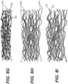
- FIG. 2 illustrates an example image of a standalone Al 2 O 3 nanofiber separator membrane 201.
- the membrane in this example was prepared by coating a Al 2 O 3 nanofiber dispersion on a substrate, drying the coating and removing from a substrate.
- the Al 2 O 3 nanofiber dispersion was prepared from blocks (bulk pieces) of as-produced Al 2 O 3 nanofibers by suitable wet milling conditions.
- FIG. 3 illustrates an example scanning electron microscopy (SEM) cross-sectional micrograph of a separator membrane 301 made from Al 2 O 3 nanofibers produced by oxidation of an aluminum alloy melt.
- the membrane in this example was prepared from a Al 2 O 3 nanofiber dispersion, which, in turn, was prepared from blocks (bulk pieces) of as-produced Al 2 O 3 nanofibers by suitable wet milling (milling in a liquid media) conditions.
- milling conditions such as speed, media size or diameter, media mass, vessel geometry, type of milling, etc.
- dispersion characteristics such as final aspect ratio and final size distribution of small fibers or their small bundles.
- a roller mill may be used to disperse a bulk of small fibers (or flakes) to achieve final fiber (or flake) aspect ratios in excess of 10,000. In some examples a roller mill may be used to disperse a bulk of small fibers (or flakes) to achieve final aspect ratios in excess of about 5,000. In some examples, a roller mill may be used to disperse a bulk of small fibers (or flakes) to achieve final aspect ratios in excess of about 1,000.
- the milling media diameter may be selected in between around 0.01 cm and around 0.1 cm. In some examples, the milling media diameter may be selected in between around 0.1 cm and around 1 cm. In some examples, the milling media diameter may be selected in between around 1 cm and around 5 cm. In some designs, milling media of different sizes (e.g., diameters) and/or compositions may be combined to achieve the most desirable dispersion.
- the optimal size (e.g., diameter) of the milling media may depend on the fiber (or flake) dimensions and properties, speed of mechanical agitation, size of the vessel, density of the milling media and/or other conditions.
- a milling media diameter e.g., below around 0.01 cm
- Such a dispersion may have poor coating qualities, such as non-wetting to the substrate, nonuniform coating thickness, and macro-porosity (vacant spaces of disconnected film within the coating), among others.
- a separator film or membrane made from a dispersion with poor coating qualities may have a weakened puncture and tensile strength, may be more susceptible to shorting during cell fabrication or during cycling, and may exhibit inferior ion transport properties.
- the resulting dispersion may consist of many bundles of large aspect ratio wires, as a media with a diameter much larger than the width of the nanowire may not be able to efficiently interact.
- Such a dispersion may create a coating film or separator membrane with poor surface uniformity and micro-porosity (vacant spaces between the large fiber bundles of an undesirable large size).
- a film made from a dispersion with poor coating qualities would have weakened puncture and tensile strength, and is more susceptible to shorting.
- the suitable milling media material may be yttria (Y 2 O 3 ) stabilized zirconia oxide (YZT), corundum (Al 2 O 3 ), steel, tungsten carbide, etc., to provide a few examples.
- the milling media material may have a large effect on the properties of the dispersion. For example, if the media is not sufficiently dense, the media may not have enough inertia to break up and disperse large bundles of nanowires at a given milling speed. Conversely, if the milling media has a density greater than desired it may cause fracturing of the fibers (or flakes) perpendicular to their "long axis", resulting in the particles with an undesirably small aspect ratio.
- polymer(s) in some designs with plasticizers
- surfactant(s) may be added to the slurry during milling to assist in the formation of stable colloids comprising individual small fibers (or flakes) or agglomerates of only a relatively small number of small fibers or flakes (e.g., about 2 to about 2,000).
- the suitable loading of small ceramic (e.g., oxide) fibers (or flakes) in the milling vessel may be between about 0.01 and about 1 wt. % of the total dispersion (e.g., flakes/fibers + media + solvent + additives) mass. In some examples, the suitable loading of the small ceramic (e.g., oxide) fibers (or flakes) in the milling vessel may be between about 1 and about 10 wt. % of the total mass of the dispersion. In some designs, if the weight percent is too high, then the milling may take an excessively long time, or the media may not impact the small fibers (or flakes) in the desired fashion needed to create a substantially uniform and stable dispersion.
- the loading of the small fibers (or flakes) may have a direct effect on the final viscosity of the dispersion, which may be a critical parameter for the final separator coating (or separator membrane) quality. For example, if the weight percent is too low, then the milling media may undesirably wear excessively due to media-media impacts/interactions during milling and the dispersion viscosity may be lower than desired.
- the loading of milling media in the milling vessel may be between about 1 and about 50 wt. % of the total mass/weight of (flakes/fibers, solvent and additives) combined. In some examples, the loading of milling media in the milling vessel may be between about 50 and about 100 wt.
- the loading of milling media in the milling vessel may be between about 100 and about 200 wt. % of the total mass/weight of (flakes/fibers, solvent and additives) combined. In some examples, the loading of milling media in the milling vessel may be between about 200 and about 300 wt. % of the total mass/weight of (flakes/fibers, solvent and additives) combined. In an example, if the weight percent of the milling media is too low, then the milling may take an excessively long time, or the media may not impact the nanowires in the desired fashion needed to create a substantially uniform and stable dispersion.
- the loading of the milling media may have a direct effect on the final viscosity of the dispersion, which may be a critical parameter for final separator film / membrane quality.
- the weight percent of the media is too high, then the milling media may wear excessively due to media-media impact and the dispersion viscosity may be lower than desired.
- the rotational speed of the milling vessel may have a significant impact on the quality of the dispersions and may depend on the size and density of the milling media, the density and mechanical properties of the small fibers (or flakes), the difference in density of the fibers and solvent, the size of the milling vessel, and/or other parameters.
- a suitable rotational speed of the milling vessel may be between about 50 and about 100 rpm. In some examples, the suitable rotational speed of the milling vessel may be between about 100 and about 200 rpm. In some examples, the suitable rotational speed of the milling vessel may be between about 200 and about 300 rpm. In some examples, the suitable rotational speed of the milling vessel may be between about 300 and about 400 rpm.
- the suitable rotational speed of the milling vessel may be between about 400 and about 600 rpm. In some examples, the suitable rotational speed of the milling vessel may be between about 600 and about 2000 rpm. In some examples, the suitable speed of the milling vessel may be between about 0.3 and about 1 m/sec. In some examples, the suitable speed of the milling vessel may be between about 1 and about 2 m/sec. In some examples, the suitable speed of the milling vessel may be between about 2 and about 3 m/sec. In some examples, the suitable speed of the milling vessel may be between about 3 and about 6 m/sec. In some examples, the suitable speed of the milling vessel may be between about 6 and about 14 m/sec.
- the resulting dispersion may comprise small fibers of an undesirably low aspect ratio (e.g., all the way down to near-spherical nanoparticles).
- a separator layer e.g., a standalone separator membrane or a separator coating film
- a separator layer made from such an undesirable dispersion may be prone to brittleness and cracking and may have poor mechanical properties, such as weakened puncture and tensile strength and be more susceptible to shorting (e.g., during fabrication and/or cycling).
- the resulting dispersion may consist of a heterogeneous mixture of small fibers (or flakes) with undesirably board distribution of aspect ratios, as the rotational speed of the mill may not give the media sufficient energy to break up large bundles of fibers (flakes).
- Such a dispersion may create a film with poor surface uniformity and micro-porosity (e.g., vacant spaces between the large fiber bundles of an undesirably large size).
- a separator layer (e.g., a standalone separator membrane or a separator coating film) made from such an undesirable dispersion may exhibit poor qualities (such as weakened puncture and tensile strength and be more susceptible to shorting during cell construction or operation).
- the suitable milling time may range from around 10 to around 30 minutes. In some examples the suitable milling time may range from around 30 to around 60 minutes. In some examples the suitable milling time may range from around 60 to around 120 minutes. In some examples the suitable milling time may range from around 120 to around 240 min. In some examples the suitable milling time may range from around 240 to around 480 minutes. In some examples the suitable milling time may range from around 480 minutes to five days.
- the resultant milled product (e.g., a milled mixture of small ceramic fibers or flakes with solvent and/or additives, etc.) may be characterized as a slurry.
- the suitable final slurry viscosity may range from around 50 to around 500 centipoises. In some examples, the suitable final slurry viscosity may range from around 500 to around 1000 centipoises. In some examples, the suitable final slurry viscosity may range from around 1000 to around 2000 centipoises. In some examples, the suitable final slurry viscosity may range from around 2000 to around 10,000 centipoises.
- the final slurry viscosity when creating a stable and functional dispersion of ceramic small fibers (or flakes), the final slurry viscosity may be a critical parameter which may be controlled by loading of milling media, loading of small ceramic fibers (or flakes), solvent composition, additive composition and/or processing conditions.
- the above-noted conditions that can be used to control the final slurry viscosity containing the small ceramic fibers (or flakes) may be quite distinct from the conditions that may be used to make a dispersion of nanoparticles with a similar viscosity.
- a desirable dispersion may have a certain viscosity, but not all dispersions with a certain viscosity are desirable.
- a suitable slurry formulation 8 g of bulk small Al 2 O 3 fibers produced by oxidation of an Al alloy melt were broken into approximately 0.05 g pieces and placed in an 8 oz jar. Then, 16 pieces of 1 ⁇ 2" diameter steel media were added to a jar together with 200 ml of ethanol and no additives (no salts and no solvent additives). The sample was mixed on a roller milled at 160 rpm for 12 hours to achieve a good quality of the dispersion with the desirable uniformity and individuality of the small fibers and desirable aspect ratio.
- the milling conditions that are optimal for achieving good dispersion of small fibers (or flakes) from the bulk may be distinctly different from those conditions that are optimal for nanoparticles or large particles.
- a media of size of about 0.1 mm or smaller should preferably be used.
- the speed of the mill and loading ratio should preferably be further optimized to the type of particle being milled, as well as the solvent and milling time.
- dispersion of small fibers with about 100 nm diameter it may be preferred to use media size of about 1 mm or larger.
- particles with dimensions on the order of approximately 100 ⁇ m may be size reduced by milling with a media sized on the order of about 10 mm to an average longest dimension (e.g., length of fibers or width of flakes) of approximately 10 ⁇ m.
- the media size can be chosen to target the largest dimension (length) of the fiber for size reduction. For example, if the fibers are on the order of about 100 ⁇ m long and about 100 nm in diameter, then choosing a large media diameter such as about 10 mm may preferentially size-reduce the length of the fibers to approximately 10 ⁇ m.
- the nanofibers may be broken up by the milling media to a maximum size of about 10 ⁇ m, but the majority will be even smaller as the bundles may preferentially fracture into about 100 nm diameter single fibers with an average length below approximately 10 ⁇ m.
- the aspect ratio of the small fibers (or flakes) in a final dispersion may preferably be in the range from around 1:4 to around 1:1,000,000.
- the aspect ratios may range from around 1:50 to around 1:500.
- the aspect ratios may range from around 1:500 to around 1:5,000.
- the aspect ratios may range from around 1:5,000 to around 1:50,000.
- the aspect ratio may affect separator layer (e.g., a standalone separator membrane or a separator coating) mechanical properties (including flexibility, strength and toughness) as well as pore size distribution and density.
- larger fibers may preferably exhibit smaller average aspect ratio (e.g., by about 2 times or by about 4 times or even more) compared to small fibers or small flakes (if flakes are used instead of or in addition to fibers).
- a dispersion of small fibers (e.g., with an average diameter between about 5-8 nm) with an average aspect ratio of around 1,000 may be mixed in at about 2:1 wt. ratio with another dispersion of larger fibers (e.g., with an average diameter between about 40-60 nm) with an average aspect ratio of around 250.
- This dispersion mixture can be characterized by having a bi-modal aspect ratio distribution characteristic of the two parent dispersions.
- This mixed suspension may then be utilized for the preparation of an effective separator layer (e.g., a standalone separator membrane or a separator coating).
- a dispersion of small fibers e.g., average diameter between about 5-8 nm
- another dispersion of larger fibers e.g., average diameter between about 40-60 nm
- This dispersion mixture can be characterized by having a bi-modal aspect ratio distribution characteristic of the two parent dispersions.
- This mixed suspension may then be utilized for the preparation of another effective separator layer (e.g., a standalone separator membrane or a separator coating).
- a dispersion of small fibers e.g., average diameter between about 5-8 nm
- an average aspect ratio of around 1,000 may be mixed in at about 4:1 wt. ratio with another dispersion of small porous flakes (e.g., average thickness between about 3-6 nm) with an average aspect ratio of around 200.
- This dispersion mixture can be characterized by having a bi-modal aspect ratio distribution characteristic of the two parent dispersions.
- This mixed suspension may then be utilized for the preparation of another effective separator layer (e.g., a standalone separator membrane or a separator coating).
- separator layer e.g., a standalone separator membrane or a separator coating
- nanostars, nanorings, planar and three-dimensional dendritic nanostructures, among others may be utilized for the preparation of the separator layer (e.g., a standalone separator membrane or a separator coating) in other embodiments of the disclosure.
- the additive(s) may also be sprayed onto the separator layer (e.g., a standalone separator membrane or a separator coating) (or the dried fibers or flakes), deposited on the top of the separator coating (or a separator membrane), or be introduced as a gaseous media (vapor), among other ways of additions.
- the separator layer e.g., a standalone separator membrane or a separator coating
- the dried fibers or flakes deposited on the top of the separator coating (or a separator membrane)
- vapor gaseous media
- oxide fibers or flakes e.g., small Al 2 O 3 fibers or flakes
- fibers may require high temperatures (e.g., above around 800 °C) to induce bonding to each other (e.g., via sintering) and may undesirably coarsen during the heat-treatment process.
- Coarsening may cause an undesirable reduction in porosity and flexibility and may increase brittleness and fracture toughness. Therefore, in some designs, it may be desirable to utilize anti-coarsening agents to either achieve bonding (e.g., sintering) at low temperatures where no substantial coarsening takes place or to reduce (minimize) coarsening at high temperatures.
- suitable additives may take the form of alkali hydroxides (such as LiOH, NaOH, KOH, etc.). Such hydroxides may transform into oxides upon heating and may form eutectics with small oxide (e.g., Al 2 O 3 , MgO, ZrO 2 , etc.) fibers (or flakes), thereby enabling lower sintering temperatures.
- alkali hydroxides such as LiOH, NaOH, KOH, etc.
- Such hydroxides may transform into oxides upon heating and may form eutectics with small oxide (e.g., Al 2 O 3 , MgO, ZrO 2 , etc.) fibers (or flakes), thereby enabling lower sintering temperatures.
- such additives are introduced into either the dispersion (suspension) of fibers (or flakes) or into the pre-formed separator layer (e.g., a standalone separator membrane or a separator coating), heat-treated at temperatures sufficiently high to provide moderate mobility but sufficiently small to induce transformation to oxide to be primarily located at the areas where neighboring fibers (or flakes) touch each other.
- the pre-formed separator layer e.g., a standalone separator membrane or a separator coating
- separator membranes may first be formed not from the small elongated ceramic (e.g., oxide) particles of suitable shape and size (e.g., small fibers or small flakes, etc.), but rather from the small elongated particles (e.g., small or large fibers or small flakes or their mixtures, etc.) of organometallic compounds (e.g., metal alkoxides, such as aluminum alkoxides, such as aluminum ethoxide, among many others).
- suitable shape and size e.g., small fibers or small flakes, etc.
- organometallic compounds e.g., metal alkoxides, such as aluminum alkoxides, such as aluminum ethoxide, among many others.
- a small amount of concentrated solution of LiOH in one solvent (“solvent A”) (dry butanol in this example) may be added to a suspension of small aluminium (or magnesium or other suitable metal) alkoxide (e.g., aluminum ethoxide or magnesium isopropoxide, etc.) fibers (e.g., about 50-100 nm in diameter) dispersed in another solvent (“solvent B”) (dry ethanol in this example).
- solvent A dry butanol in this example
- solvent B dry ethanol in this example
- the mixture may then be coated on a substrate to form a thin (e.g., approximately 20 micron thick) film. Once a dry film is left, the hydroxide and alkoxide phases may be converted to oxide phases by heating the samples in an oxidizing environment (e.g., dry air) at elevated temperatures (e.g., at about 300-1100 °C).
- an oxidizing environment e.g., dry air
- the heat-treatment of the deposited membrane in a controlled environment may soften the organometallic particles (e.g., small alkoxide fibers), while the ceramic particles (e.g., small oxide fibers) help the mixture to retain a desired shape.
- the heat-treatment may then bond the small oxide fibers to small alkoxide fibers, whereby the oxide fibers bond (link) the alkoxide fibers together.
- Further heat-treatment of the membrane in an oxidizing environment may convert the alkoxide into oxide forming an oxide membrane with the desired properties (e.g., sufficient strength, flexibility, porosity, etc.).
- Similar additives may also be used for the mixture of the alkoxides and oxides as for the pure oxide particles (e.g., fibers, flakes, etc.).
- suitable additives may take the form of alkali nitrate salts (such as LiNO 3 , NaNO 3 , KNO 3 , CsNO 3 , among others), which may also decompose and react with ceramic (e.g., oxide) or organometallic (e.g., alkoxide) fibers or flakes or other particles in the original dispersion.
- ceramic e.g., oxide
- organometallic e.g., alkoxide
- a small amount of concentrated solution of lithium nitrate in a solvent A may be added to a solution of aluminium alkoxide (ethoxide, in this example) nanowires dispersed in a solvent B.
- suitable additives may also take the form of alkali alkoxides, including LiOR, NaOR, KOR, CsOR, where R is an alkane with carbons numbering from 1 to 10.
- lithium alkoxides to small alkoxide fibers (or flakes) (e.g., to aluminum or magnesium alkoxides) in various organic solvents in order to control the relative solubility of the alkoxides (e.g., to enable the precipitation of Li alkoxide within the small metal alkoxide fibers to later be used as a sintering agent).
- a small amount of concentrated solution of lithium alkoxide in a solvent A may be added to a solution of small aluminum alkoxide fibers dispersed in a solvent B. The mixture is then coated on a substrate as a thin film (e.g., between about 3-50 micron).
- solvent B has a higher vapor pressure than solvent A, as solvent B evaporates, lithium alkoxide will begin to precipitate, nucleating at the junctions of the aluminum alkoxide nanowires where the most surface area is available.
- solvent A may be a dry alcohol like butanol or another suitable solvent
- solvent B may be a dry alcohol like methanol or another suitable solvent.
- At least a portion of the organometallic (e.g., alkoxide) fibers (or flakes or other suitable particles) may be at least partially converted into hydroxide or oxyhydroxide fibers (or flakes or other suitable particles) prior to transformation to ceramic (e.g., oxide) fibers (or flakes or other suitable particles).
- ceramic e.g., oxide
- such an intermediate phase may assist in bonding these fibers (or flakes or other suitable particles) to form a mechanically robust porous membrane with desired flexibility and porosity.
- a box furnace, tube furnace, belt furnace, inductive heater or other device may be utilized for heat-treatment.
- the suitable processing temperature may range from between around 100 °C and around 1100 °C in case of the formation of the Al 2 O 3 separator membrane and between around 100 °C and around 2000 °C in case of the formation of the MgO separator membrane.
- the suitable processing temperature may range from between around 100 °C and around 2000 °C.
- the sintering temperature may preferably be optimized to match the chemistry of the additive, such that the melting point or chemical reaction (i.e., a phase transformation or eutectic melt) enabling the sintering of the small (e.g., oxide) fibers is at a lower temperature than required without an additive.
- the melting point or chemical reaction i.e., a phase transformation or eutectic melt
- the gaseous environment e.g., H 2 O, among others
- the gaseous environment may significantly enhance surface diffusion (relatively to the bulk diffusion) of species on the surface of small fibers so that the bonding may take place at sufficiently low temperatures where undesirable coarsening does not proceed at an undesirably fast rate.
- reactive gas may be applied with heat to the small ceramic (e.g., oxide) or organometallic (e.g., alkoxide) fibers (or flakes or other suitable particles).
- a heating rate and a ratio of reactive gas flow to non-reactive gas flow may be optimized for the most favorable membrane formation.
- reactive to non-reactive gas ratios may range from around 0.1 to 0.990 and temperature ramp rates may generally range from around 0.1 °C/min to around 1000 °C/min, depending on the composition and chemistry of the mixture, pressure and environment (e.g., atmosphere).
- reactive gases include but are not limited to CO 2 , H 2 O, NH 4 OH, NH 3 , O 2 , H 2 , and NF 3 .
- non-reactive gases include Ar, N 2 , and other noble gases.
- laser treatment or plasma treatment may be used to induce bonding between the small ceramic (e.g., oxide) or organometallic (e.g., alkoxide) fibers.
- small ceramic e.g., oxide
- organometallic e.g., alkoxide
- mechanical (or hydrostatic) pressure may be advantageously applied during sintering (bonding) to increase the surface area contact between the fibers during the sintering (bonding) process.
- pressure may be applied by hot press, pressure by gravity, negative pressure by dynamic vacuum.
- the heat applied to the small ceramic (e.g., oxide) or organometallic (e.g., alkoxide) fibers (or flakes or other suitable particles) may use a particular ramp rate during heating stage(s) for the most favorable membrane formation.
- suitable ramp rates may generally range from around 0.1 °C/min to around 1000 °C/min, depending on the composition and chemistry of the mixture, pressure and environment (e.g., atmosphere).
- a polymer separator may comprise oxide particles incorporated within pores or on one of its surfaces.
- the primary function of the polymer separator is to electrically separate the anode and cathode, while the oxide particles are added to provide an extra level of safety at elevated temperatures where the polymer membrane may shrink and fail.
- the overall thermal stabilities of such composite membranes may be rather poor, the adhesion of the particles to the membrane may not be very good (e.g., ceramic particles may fall off the membrane during handling) and overall thickness of such composite membranes is typically rather larger (e.g., about 1-30 microns in some designs, and within about 15-30 microns in other designs).
- One or more embodiments of the present disclosure provide for the addition of polymeric additive(s) to serve primarily as an improved mechanical support or as binder that bonds (or helps to bond) small ceramic (e.g., oxide) fibers (or other suitable particles such as flakes or their mixtures) together (or, in some designs, to the electrode or to another membrane).
- polymeric additive(s) to serve primarily as an improved mechanical support or as binder that bonds (or helps to bond) small ceramic (e.g., oxide) fibers (or other suitable particles such as flakes or their mixtures) together (or, in some designs, to the electrode or to another membrane).
- the addition of a polymer enhances mechanical properties of the small fiber-comprising separator membranes or separator membrane layer (e.g., strength, flexibility, adhesion, fracture toughness, etc.).
- the addition of the polymer to the membrane may reduce or prevent electrochemical reduction of the small ceramic (e.g., oxide) fibers (or other suitable particles such as flakes or their mixtures) if the separator membrane directly contacts the anode at potentials where electrochemical reduction may generally take place.
- the small ceramic e.g., oxide
- the separator membrane directly contacts the anode at potentials where electrochemical reduction may generally take place.
- lithium or graphite or Sn or Si-comprising anode in a Li-ion battery may be exposed to sufficiently low potentials that may induce undesirable electrochemical reduction of the oxide (or ceramic) fibers in direct contact with it, leading to irreversible Li losses.
- a thin layer of a polymer binder between the anode and the membrane or the addition of small amount of a polymer binder into the membrane may prevent such an undesirable outcome.
- the polymer component of the membrane may be in the form of polymer fibers (including porous fibers and small fibers) or polymer flakes (including small flakes and porous flakes) or polymer comprising composite fibers or polymer-comprising composite flakes.
- Such polymer fibers (or flakes) may bond with or/and entangle with the small ceramic fibers (flakes) to enhance mechanical properties or processability of the separator membrane. Due to higher elasticity (and deformability) of the polymer component, the polymer component may help to form bonds with ceramic particles over a larger contact area and thus may enhance the overall strength of the membrane.
- the polymer component may enhance overall elasticity of the membrane and the overall toughness of the membrane.
- the polymer component e.g., fibers or flakes
- the polymer component may help to form more stable suspension of ceramic particles for more uniform separation layer formation.
- the polymer fibers or flakes may have smaller dimensions or aspect ratio than ceramic fibers or flakes (e.g., the polymer fibers or flakes may be in the range from around 1 nm to around 200 nm in diameter or thickness).
- a smaller polymer fiber diameter may allow higher fraction of chemical groups (relative to the total polymer mass) and, additionally, may allow the polymer fibers or flakes to be more easily deformable (e.g., curve around ceramic particles) and thus potentially form more bonds with the ceramic particles.
- smaller polymer fibers (or flakes) may exhibit higher (cross-area normalized) strength (relative to larger polymer fibers or flakes).
- larger fiber dimensions may lead to higher fiber strength on an absolute basis and thus may be advantageous in some designs. So, in other designs, polymer fibers or flakes may have larger dimensions or aspect ratio that ceramic fibers or flakes (e.g., be in the range from around 200 nm to around 10 microns in diameter or thickness).
- polymer fibers or flakes may form primary (chemical) bonds with ceramic particles in the membrane.
- polymer fibers or flakes may form secondary bonds with ceramic particles (the advantageous of which have been already discussed).
- the aspect ratio of the polymer fibers or polymer flakes may range from around 10 to around 10,000,000.
- the individual polymer flakes or fibers may exhibit tensile strength in the range from around 10 MPa to around 10 GPa.
- polymer fibers (or nanofibers) with such thermal and mechanical properties include, but are not limited to various cellulose fibers (or nanofibers), various chitin fibers (or nanofibers), various aramid fibers (or nanofibers), among many others.
- the individual polymer flakes or fibers may comprise functional groups that may for primary or secondary bonds with ceramic fibers (including small fibers) or flakes (including small flakes).
- the ceramic-comprising separator layer may exhibit a tensile strength (measured at room temperature in air) in the range from around 1 MPa to around 1,000 MPa. In some designs, it may be advantageous for the ceramic-comprising separator layer to exhibit a tensile strength in the range from around 1MPa to around 1,000 MPa in the operating temperature range (particular temperature range may depend on the application; in some designs, it may range, for example, from as low as - 70 °C to as high as + 200 °C).
- the ceramic-comprising separator layer may exhibit a room-temperature tensile strength in the range from around 1 MPa to around 1,000 MPa when immersed into electrolyte or electrolyte solvent mixture.
- the ceramic-comprising separator layer may exhibit a compressive strength (in air, measured at room temperature) in the range from around 1 MPa to around 2,000 MPa. In some designs, it may be advantageous for the ceramic-comprising separator layer to exhibit a compressive strength in the range from around 1MPa to around 2,000 MPa in the operating temperature range (particular temperature range may depend on the application; in some designs, it may range, for example, from as low as - 70 °C to as high as + 200 °C).
- the ceramic-comprising separator layer may exhibit a room-temperature tensile strength in the range from around 1 MPa to around 1,000 MPa when immersed into electrolyte or electrolyte solvent mixture.
- the ceramic-comprising separator layer may exhibit air permeability from around 1 L/m 2 sec to around 50,000 L/m 2 at 200 Pa (applied pressure difference across the membrane), depending on the application and the permeability of the support electrode or membrane (if present). Higher air permeability may be advantageous for high-rate applications in batteries and supercapacitors.
- the ceramic-comprising separator layer may exhibit pore exclusion size of no more than around 1 micron (e.g., from around 10 nm to around 1,000 nm). That is even if larger pores may exist in the separator layer they may be connected only with sub-micron pores so that no particles larger than, say, 1 micron (or a particular pore exclusion size) may penetrate through the membrane.
- polymer-ceramic membranes may be advantageously heat-treated (including heat-treatment under applied pressure) at temperatures in the range from around 40 to around 300 °C (depending on the polymer composition and properties, such as glass transition temperature, decomposition temperature, thermal expansion and others) to enhance membrane mechanical properties or purity.
- the polymer-comprising composite membrane that comprises small ceramic (e.g., oxide) fibers (or other suitable particles such as flakes or their mixtures) may comprise composite fibers that comprise both smaller ceramic (e.g., oxide) fibers and polymer(s).
- the fraction of such composite fibers in the separation membrane may range from around 1 to around 100 wt. %.
- Such composite fibers may be produced by various spinning techniques, such as blow-spinning (e.g., melt spinning or solution spinning), electrospinning and more traditional spinning techniques (e.g., wet spinning, dry-jet spinning, dry spinning, etc.).
- blow-spinning e.g., melt spinning or solution spinning
- electrospinning e.g., wet spinning, dry-jet spinning, dry spinning, etc.
- blow spinning and electrospinning may produce much smaller diameter composite fibers (down to 10 nm, provided small ceramic fibers are 10 nm or smaller). During spinning, in some designs, most of the small ceramic fibers may orient parallel to the fiber length.
- the relative weight, distribution and volume fractions of the polymer in various (such as those described above) polymer-small ceramic fiber (or polymer-small ceramic flakes or, more generally, polymer-ceramic particle) composite membranes will determine their thermal, physical and chemical properties and may be optimized for specific applications. For example, a higher fraction of the polymer component may lead to reduced polarity, reduced thermal stability, increased thermal expansion, lower strength, higher flexibility, higher maximum elongation, easier processability and/or reduced oxidation stability.
- a higher fraction of the small ceramic (e.g., oxide) fibers may lead to better electrolyte wetting, higher average dielectric constant, surface dipoles and electrostatic interactions with particles, higher mechanical strength (particularly under compression), higher abrasive resistance, lower thermal expansion coefficient, and/or better thermal stability.
- the highest fracture toughness or modulus of toughness for such membranes may be achieved for some optimum weight fractions of the components (depending on the processing conditions, size, properties and shape of the small ceramic fibers, properties and shape of the polymer components, bonding between the polymer and ceramic particles, contact area between the polymer and ceramic particles, etc.).
- a suitable amount of the polymer component (or binder) in the separator membrane may generally range from around 0.0 wt.% to around 80.0 wt. % (depending on the application, preparation conditions and the desired separator membrane properties).
- an excessive fraction of the polymer component may lead to reduced membrane permeability and porosity and reduced wetting by electrolyte, reduced thermal stability, among other undesirable membrane properties.
- small ceramic (e.g., oxide) fibers may provide most of the electrical separation between anode and cathode, although the polymeric additive(s) may still provide some level of increased electrical separation between the anode and cathode.
- the relatively small wt. % of the added polymer e.g., about 0.1-20 wt. % relative to the total dry composite membrane weight
- the small ceramic (e.g., oxide) fibers (or other suitable particles such as flakes or their mixtures) may be targeted to bind the small ceramic (e.g., oxide) fibers (or other suitable particles such as flakes or their mixtures) together at their junctions or to the electrode layers themselves to better accommodate any changes in the size of the electrode(s) during cycling.
- polymer binders may be added to small ceramic (e.g., oxide) fiber (or flakes or other particle types) dispersion in the amount of about 0.001-0.01 wt. % (relative to the total mass of the oxide fibers or other oxide particles and solvent) loadings.
- binders are added to small fiber dispersions in about 0.01 - 0.1 wt. % loadings (relative to the total mass of the oxide fibers or other oxide particles and solvent) and in yet other examples, the binders may be added to the dispersions in about 0.1-50 wt.
- the relative fraction of the small ceramic (e.g., oxide) fibers in the polymer-ceramic composite membranes may range rather broadly, from around 5 wt. % to around 99.9 wt. %.
- the polymer component may also help to achieve uniform distribution of the ceramic particles in the membrane layer.
- the polymer component may form primary (chemical) bonds with ceramic particles.
- the polymer component may form secondary (e.g., hydrogen or van der Waals) bonds with ceramic particles.
- both primary and secondary bonds between the polymer component and ceramic particles may exist.
- a polymer component in the composite polymer-small ceramic fiber (or polymer-small ceramic flake or, more generally, polymer-ceramic) membranes may comprise thermoset or thermoplastic polymers (either standalone or as a mixture or as a co-polymer component), including but not limited to: various polysaccharides and mixture of polysaccharides with other polymers including but not limited to proteins (e.g., arabinoxylans, gum arabic, xantham gum, pectins, chitin and chitin derivatives, cellulose and cellulose derivatives including various modified natural polymers, such as cellulose acetate (CA), cellulose acetate butyrate (CBA), carboxymethylcellulose (CMC), cellulose nitrate (CN), ethyl cellulose (EC), among others cellulose derivatives, alginates including alginic acids and its salts, etc.); acrylonitrile-butadiene-st
- polymers and co-polymers of the composite polymer-small ceramic fiber membranes may comprise at least one of the following monomer constituents: acrylates and modified acrylates (methylacrylate, methylmethacrylate, etc.), diallylphthalates, dianhydrides, amines, alcohols, anhydrides, epoxies, dipodals, imides (polyimides), furans, melamines, parylenes, phenol-formaldehydes, polyesters, urea-formaldehydes, urethanes, acetals, amides, butylene terephthalates, carbonates, ether ketones, ethylenes, phenylene sulfides, propylenes, styrene, sulfones, vinyl, vinyl butyrals, vinyl chlorides, butylenes, chlorobutyls, fluorobutyls, bromobutyls, epichlorohydrins, fluorocarbons
- silane coupling agents may be used to produce robust bonds between polymer and ceramic (e.g., oxide) interfaces. These molecules may be able to link typically unreactive surfaces as they have both a functional organic group and a functional silane group (R-Si-X3 where R is an organic ligand and X is typically alkoxy, acyloxy, halogen, or amine). These groups may covalently bond or physically interact with the polymer and inorganic (ceramic, such as oxide) surfaces.
- Three main example structures of silane coupling agents include trialkoxysilane, monoalkoxysilane, dipodal silane. Bonding may proceed through hydrolysis of the silane group, creating hydroxy functional groups.
- Independent silane monomers then able to polymerize through condensation reactions.
- the hydroxy groups bound to the silicon may then able to hydrogen bond to the hydroxy bonds of the inorganic substrate, followed by a covalent linkage using oxygen as a bridge to the siloxane polymer.
- the organofunctional group that is also connected to siloxane polymers may acts as a site for organic molecules to bind chemically (e.g., covalently) or through secondary bonds / physical interactions (e.g. van der Waals, ionic interaction, hydrogen bonding, etc.).
- Anhydrous bonding may also be possible wherein monomer silane groups covalently bond via an oxane bond to the inorganic substrate.
- silane coupling agents may be used to provide more robust linking of inorganic (e.g., ceramic) to organic (e.g., polymer) components in the composite separator layer materials.
- Composite separator layers that include silane coupling agents may have increased mechanical stability, better thermal stability, higher ionic conductivity, and other enhanced properties.
- a wider range of polymer materials may also be available to use with normally incompatible (or not bonding) ceramics with the help of silane coupling agents.
- ceramic materials e.g., ceramic fibers or flakes
- Dipodal silanes may be used to increase the hydrolytic stability of ceramic-polymer matrixes.
- silane coupling agents may be introduced as a monomer constituent of a copolymer to improve mechanical strength, thermal stability, and bonding ability.
- Some examples of silane coupling agents that may be used to cross-link ceramic composite materials include but are not limited to: acrylate, methacrylate, aldehyde, amino, anhydride, azide, carboxylate, phosphonate, sulfonate, epoxy, ester, halogen, hydroxyl, isocyanate, masked isocyanate, phosphine, phosphate, sulfur, vinyl, olefin, polymeric, UV active, fluorescent, chiral, trihydro, dipodal, among other functional silanes.
- the composite membranes may be advantageous for the composite membranes to utilize thermally stable polymers that maintain at least 50% of their room-temperature tensile strength at elevated temperatures in the range from about 120.0 °C to about 450.0 °C in either an inert environment or in air (in some designs it may be preferred for such thermal stability temperature to exceed 150 °C or even 200 °C).
- such polymers may advantageously comprise nitrogen (N) and/or fluorine (F) in their atomic composition.
- the atomic fraction of either N or F or both (N+F) may range from around 5 at. % to around 70 at. %.
- polymers include, but are not limited to viton (chemical structure (C 3 F 6 ) n (C 2 H 2 F 2 ) m ) and various polyimides (particularly semi-aromatic and aromatic polyimides) (e.g., polyimide (III) of pyromellitic anhydride and p,p'-diaminodiphenyl ether, poly-oxydiphenylene-pyromellitimide, among many others).
- polyimides particularly semi-aromatic and aromatic polyimides
- the composite polymer-small particles e.g., small ceramic fibers, small ceramic flakes, etc.
- UV ultraviolet
- a metal salt or salt mixture may be added to the suspension (dispersion) of small alkoxide or oxide fibers (e.g., flakes or other suitable particles or particle mixtures) either prior to forming a separator membrane or infiltrated into the membrane after its pre-formation and drying.
- a salt or salt mixture may comprise various anions (e.g., F - , Cl - , Br - , I - , NO 3 - , SO 4 - , CO 3 2- , C 2 O 4 2- , ClO 4 - , BF 4 - , PF 6 - as well as the hydrated forms of these and other compounds).
- suitable organic anions in suitable salts may include (but are not limited to) acetate and substituted acetates, 2-ethylhexanoate and substituted carboxcylic acids, cyclopentadienide, substituted cyclopentadienide, cyclooctadienide and substituted cyclooctadienide, trifenylphosphine and substituted trifenylphonephine, acetylacetonate and substituted acetylacetonates, diketimines and substituted diketimines, bipyridene and substituted bipyridene, Bis[1-N,N-dimethylamino)-2-propanolato (DMAP), acetonitrile dihalides, carbonyl and substituted carbonyls, cyclohexanes and substituted cyclohexanes, stearates and substituted stearates, porphyrins and substituted porphyrins
- Examples of cations (or their mixtures) in suitable salts include, but are not limited to Al 3+ , Li + , Na + , Mg 2+ , Ca 2+ , Cr 3+ , Cr 4+ , Cr 5+ , Cr 6+ , K + , Zr 4+ , Zn 2+ , Sr 2+ , Ti 4+ , Sc 3+ , Fe 2+ , Fe 3+ , Cu 2+ , among others.
- Rb + , Co 2+ Co 3+ , Ni 2+ , Mn + , Mn 2+ , Mn 3+ , Mn 4+ , Mn 5+ , Mn 6+ , Mn 7+ , Ta 3+ , Ta 4+ , Ta 5+ , Si 4+ , Ge 4+ , La 3+ , V 5+ , V 3+ , Cs + , Ba 2+ , Sr 2+ and others may also be utilized.
- Such a salt or salt mixture may be dissolved in a compatible solvent prior to its addition. These metal salts may then be transformed into oxides by exposure to UV light and bond neighboring particles (e.g., small fibers or flakes, etc.) to form a robust yet flexible separator layer (e.g., a standalone separator membrane or a separator coating).
- a robust yet flexible separator layer e.g., a standalone separator membrane or a separator coating.
- metal alkoxides such as Ga(OR) 3 , Ti(OR) 4 , Zr(OR) 4 , V(OR) 5 , Ni(OR) 2 , CuOR, Zn(OR) 2 , LiOR, NaOR, KOR, Mg(OR) 2 , Ca(OR) 2 and others may be added to the dispersion of ceramic (e.g., oxide) small fibers and other particles for conversion into an oxide by exposure to UV light and oxygen containing atmosphere (such as ambient atmosphere).
- ceramic e.g., oxide
- the low temperature of this process makes it particularly attractive as it minimizes thermal stresses and makes it compatible with thermally sensitive substrates (e.g., makes it very attractive for the formation of separator layer as a coating on the surface of electrodes or separator).
- siloxane may be used as a bonding additive, which may be converted to SiO 2 .
- O 2 may be converted to O 3- with 185 nm UV light, then O 3- may photo-dissociate under exposure to 254 nm UV light to form molecular oxygen and atomic oxygen. Atomic oxygen may then react with siloxane (or metal alkoxides) to form SiO 2 (or metal oxides).
- an SiO 2 bonding agent may be formed by the vapor-phase chemisorption of organosilane and subsequent photooxidation using 172-nm vacuum ultraviolet (VUV) light.
- VUV vacuum ultraviolet
- the UV exposure may take place at elevated temperatures.
- such an elevated temperature may range from around +30 °C to around 1200 °C.
- extra-thin e.g., less than about 5-10 ⁇ m
- highly porous e.g., porosity greater than about 75 % total porosity
- aluminum oxide or other suitable oxide and suitable ceramic
- membranes may allow for noticeably increased rate capability and energy density of Li and Li-ion batteries as well as that of other batteries, while increasing or maintaining a required level of safety.
- This level of porosity beneficial for high rate capabilities, in combination with mechanical integrity and flexibility may be attainable using small fiber-like or flake-like structures.
- 'regular' (e.g., near-spherical) particle-based ceramic structures by contrast require substantially denser packing to produce a mechanical network and are typically not very flexible.
- such membranes may be used in combination with high voltage cathodes (e.g., cathodes having an average lithiation potential from around 3.9 to around 5.6 V vs. Li/Li+) in Li and Li-ion battery cells.
- high voltage cathodes e.g., cathodes having an average lithiation potential from around 3.9 to around 5.6 V vs. Li/Li+
- small fibers or flakes may be directly deposited on at least one of the electrodes (or on another membrane) by using casting (e.g., slot-die casting or blade casting) or by spray deposition or by field-assisted deposition or by dip coating, or by another suitable method.
- such deposited fibers may serve as an integrated (thin and flexible) membrane separating anodes and cathodes from direct electrical contact, while providing small resistance to ion transport and occupying a relatively small space.
- the separator may be dried (after casting / spray drying) at temperatures in the range from around 40 °C to around 400 °C.
- FIG. 4 Illustrates an example of a small Al 2 O 3 fiber coating 403 on an electrode to produce a separator layer as a coating on a Si-based Li-ion battery anode 402 coated on a Cu foil 401.
- FIG. 5 illustrates a comparison of select performance characteristics of four full cells with a high voltage lithium cobalt oxide (LCO) cathode and a Si-based Li-ion battery anode built either with small Al 2 O 3 fiber separator of two thicknesses coated directly on the Si anode (thickSSAnode and thinSSAnode) vs. a conventional commercial polymer (PP) separator (control 4 and control 5). All tested cells were built with identical anodes and cathodes. Capacity (mAh/g) is normalized by the weight of the anode coating. Mid-cycle hysteresis (V) was recorded when cells were cycled at C/2 rate. The smaller hysteresis of the cells with the small Al 2 O 3 fiber separator layer coating is clearly visible in FIG. 5 .
- LCO lithium cobalt oxide
- PP commercial polymer
- ceramic separator layers including those produced from or comprising small fibers or small flakes, including porous small fibers and flakes
- separators in Li-ion and other batteries include MgO, ZrO 2 , various mixed oxides and many others.
- MgO, ZrO 2 various mixed oxides and many others.
- the important parameters in some designs are generally mechanical properties, stability of the ceramic membrane in electrolyte and (in case of the direct contact with positive or negative electrodes) the lack of the electrochemical side reactions (such as significant lithiation or dissolution, in contact with electrodes).
- a porous polymer layer on one or both sides of the standalone ceramic (Al 2 O 3 , MgO, ZrO 2 , etc.) separator membrane in order to further reduce small side reactions with electrodes.
- the standalone ceramic Al 2 O 3 , MgO, ZrO 2 , etc.
- a porous polymer layer e.g., porous ethylene, porous propylene, porous aramid, porous cellulose, porous saccharide, etc.
- a suitable thickness of such a porous polymer layer may range from around 10 nm to around 10 micron.
- a polymer layer it is further preferable for such a polymer layer to be stable in contact with Li and exhibit high interfacial energy at the polymer/Li interface. In this case, formation of the Li dendrite would result in a substantial increase in the energy of the system and its growth may be significantly reduced or eliminated.
- a direct contact of Li with many ceramic materials may result in the formation of the low-energy interface, which would reduce the surface energy of the Li dendrite and thus undesirably favor its propagation.
- the porous polymer layer on one or both sides of the ceramic (e.g., Al 2 O 3 , MgO, ZrO 2 , etc.) membrane may be thermally responsive (or comprise a thermally responsive layer) and close pores above certain temperature. This may provide an additional safety feature of the cell because above a certain temperature (e.g., selected in the range from about 70 °C to about 120 °C, for some applications) the membrane would shut the current flow.
- a thermally responsive layer may comprise a thermoplastic that melts above a critical temperature (e.g., selected in the range from about 70 °C to about 120 °C, for typical applications) to cut off the Li ion conduction.
- oxide e.g., aluminum oxide, magnesium oxide, zirconium oxide, etc.
- suitable ceramic small fiber or flake including but not limited to porous small fiber or flake
- separator layers e.g., standalone separator membranes or a separator coatings
- medium sized e.g., from around 10 mAh to around 200 mAh
- large e.g., from around 200 mAh to around 10,000 mAh
- extra-large e.g., above around 10,000 mAh
- cells may be particularly advantageous (e.g., due to enhanced safety particularly important for medium or large or extra-large cells).
- Example of suitable metal anode-based battery cells include, but are not limited to, cells with Li anode (e.g., as in Li metal batteries), Mg anode (e.g., as in Mg metal batteries), Na anode (e.g., as in Li metal batteries), Zn anode (many battery chemistries comprising Zn or Zn alloy anodes and electrolytes that do not induce dissolution or reduction of small wire membranes), K anode (e.g., as in K metal batteries), to name a few.
- rechargeable metal anode batteries may particularly benefit from this membrane technology.
- Metal anodes in such rechargeable battery cells may undergo metal stripping (dissolution into electrolyte as ions) during discharging and re-plating during charging. This process may lead to the formation of dendrites that may induce internal shorting, which may lead to battery failure (and, in some case, to various safety risks such as fires, particularly known in Li battery chemistries).
- the use of solid electrolytes or surface layer protection with a solid ceramic protective layer is often expensive, not always feasible, and does not always protect the cell from dendrite penetration (particularly in situations where the battery may be shocked or exposed to various stresses, as when used in transportation).
- metal anodes e.g., Li half cells
- the use of metal anodes in commercial cells is rare because of their higher cost as well as reliability and safety concerns (larger sized cells would release more energy during dendrite-induced thermal runaway and rapid disassembling, particularly when flammable organic electrolytes are utilized).
- small fiber or flake separator layers e.g., separator membranes or separator coatings
- separator membranes or separator coatings e.g., porous aluminum oxide or magnesium oxide or zirconium oxide membranes, to provide a few examples
- a relatively high elastic modulus of the membrane material, high porosity, and (potentially importantly) small (e.g., below about 2 microns, more preferably below about 0.25 microns, on average) and tortuous pores may greatly suppress or eliminate the dendrite growth, while providing relatively fast metal (e.g., Li, Mg, Zn, etc.) deposition (plating) and thus high power density.
- relatively fast metal e.g., Li, Mg, Zn, etc.
- metal dendrites may penetrate through many polymer membranes in some applications (e.g., during metal dendrite growth in a cell with a polymer separator membrane), the metal dendrites may fail to penetrate through individual small oxide fibers (e.g., small aluminum oxide fibers) even if these are coated with polymer layers. Therefore, in some applications, metal dendrite formation may require dendrites to grow around the small fibers, which may significantly increase the dendrite specific surface area.
- the small features of the membrane walls, its roughness, its dielectric properties, or its surface properties may also be responsible for the suppression of dendrite growth.
- medium or large or extra-large cells with other (non- metal) anodes may also greatly benefit from using porous, ceramic (e.g., flexible) small fiber (including but not limited to porous small fiber) or small flake separator layers (e.g., separator membranes or separator coatings) in their construction due to greatly enhanced safety, higher compressive strength, reduced ionic resistance, better thermal stability or other positive attributes.
- porous, ceramic e.g., flexible
- small fiber including but not limited to porous small fiber
- small flake separator layers e.g., separator membranes or separator coatings
- the use of ionically permeable (e.g., porous) polymer layer between the oxide (e.g., aluminum oxide, magnesium oxide, zirconium oxide, etc.) small fiber or flake (including but not limited to porous small fiber or flake) comprising membranes and at least one of the electrodes may be beneficial for their use as separators in electrochemical cells (e.g., battery cells).
- oxide e.g., aluminum oxide, magnesium oxide, zirconium oxide, etc.
- small fiber or flake including but not limited to porous small fiber or flake
- the electrodes may be beneficial for their use as separators in electrochemical cells (e.g., battery cells).
- such a polymer layer may be deposited on a membrane or on an electrode or simply sandwiched between the ceramic membrane and at least one of the electrodes. In some designs, such a polymer layer may serve different useful functions.
- the use of a polymer layer between an oxide membrane and an anode may reduce or prevent reduction of the oxide by Li or other unfavorable interactions at low potentials (e.g., below around 0.1-2 V vs. Li/Li+, depending on an oxide and electrolyte chemistry).
- low potentials e.g., below around 0.1-2 V vs. Li/Li+, depending on an oxide and electrolyte chemistry.
- aluminum, magnesium and zirconium oxides, but also many other oxides that are typically unstable or significantly less stable in contact with Li may be utilized (e.g., silicon oxides, zinc oxides, iron oxides, magnesium oxides, cadmium oxides, copper oxides, chromium oxides, titanium oxide, various combination of oxides, etc.).
- a polymer layer may prevent or minimize various undesirable interactions between an oxide and electrolyte or a cathode at higher potentials (e.g., above around 3-4 V vs. Li/Li+, depending on the oxide and electrolyte chemistry).
- such a polymer layer may serve as an additional safety mechanism. For example, it may prevent ion transport (e.g., by closing the pores or by becoming impermeable by the electrolyte solvent or by other mechanisms) if heated above a critical temperature (or cooled below a critical temperature).
- the suitable porosity of such a polymer layer may range from around 0 to around 99 vol.
- the polymer layer may be a part of a multi-layer (oxide fiber or oxide flake -comprising) membrane or may be deposited on at least one of the electrodes or be prepared as a stand-alone film.
- the composition of the polymer layer may depend on a particular functionality desirable and a particular chemistry of an electrochemical cell and may be selected from the list of polymer compositions discussed in conjunction with the polymer composites described herein.
- oxide e.g., aluminum oxide, magnesium oxide, zirconium oxide, etc.
- suitable ceramic small fibers or flakes including but not limited to porous small fibers and porous small flakes
- electrically isolative mechanical reinforcement in electrodes solid (e.g., polymer, ceramic, glass-ceramic, or composite) electrolyte and separators of various batteries (e.g., Li and Li-ion batteries, Na and Na-ion batteries, etc.) and other electrochemical energy storage devices may also be highly advantageous.
- small fibers may enhance mechanical strength, fatigue resistance, and overall durability of the electrodes without providing undesirable electrochemically active surface area for decomposition of electrolyte due to the lack of electrical conductivity in aluminum oxide and other oxides, in contrast to, for example, carbon nanotubes or carbon fibers and nanofibers.
- oxide e.g., aluminum oxide, magnesium oxide, etc.
- suitable ceramic small fibers may be advantageous for providing (and maintaining during cycling) fast ionic pathways within electrodes.
- pores in the porous oxide (e.g., aluminum oxide or magnesium oxide, etc.) small fibers may be utilized as pathways for ion access from the top surface to the bulk of the electrode.
- pores may remain filled with electrolyte but empty from electrolyte decomposition products and since mechanical strength of the oxide may be sufficiently large to withstand volume changes in the electrodes during operation without inducing collapse of the pores, in some designs such pores may be successfully utilized for maintaining high ionic conductivity within the electrode during cycling.
- FIG. 6 illustrates an example of a small oxide fiber coating 601 comprising small aluminum lithium oxide fibers produced from small aluminum ethoxide fibers that comprise lithium impurities.
- small aluminum ethoxide fibers were, in turn, produced by the exposure of Li-Al alloy particles to dry ethanol.
- FIG. 7A illustrates an example of a composite membrane 701 produced by casting from a colloidal solution comprising both small oxide fibers (Al 2 O 3 in this example) and a polymer (PVA, with average molecular weight (MW) of about 30,000).
- the PVA was dissolved in ethanol solvent and oxide fibers were suspended in such a solution.
- the weight ratio of about 91:9 (oxide:polymer) was used in this example.
- the image depicted in FIG. 7A was recorded using scanning electron microscopy (SEM).
- FIG. 7B illustrates an example curvature radius of the composite membrane 701 of FIG. 7A , whereby a small curvature radius of ⁇ 2.5 mm is achieved without breaking.
Landscapes
- Chemical & Material Sciences (AREA)
- Engineering & Computer Science (AREA)
- Chemical Kinetics & Catalysis (AREA)
- Electrochemistry (AREA)
- General Chemical & Material Sciences (AREA)
- Power Engineering (AREA)
- Manufacturing & Machinery (AREA)
- Materials Engineering (AREA)
- Microelectronics & Electronic Packaging (AREA)
- Inorganic Chemistry (AREA)
- Ceramic Engineering (AREA)
- Composite Materials (AREA)
- Cell Separators (AREA)
- Battery Electrode And Active Subsutance (AREA)
- Porous Artificial Stone Or Porous Ceramic Products (AREA)
- Electric Double-Layer Capacitors Or The Like (AREA)
- Secondary Cells (AREA)
Claims (15)
- Separator (104), dereine keramikhaltige Separatorschicht (201; 403; 701) umfasst,wobei die keramikhaltige Separatorschicht poröse Metalloxidfasern (820F, 822F) mit Durchmessern im Bereich von etwa 3 nm bis etwa 2 Mikron, Seitenverhältnissen im Bereich von etwa 20 bis etwa 100.000 und einem gesamten offenen Porenvolumen unter den Metalloxidfasern im Bereich von etwa 0,01 cm3/g bis etwa 1 cm3/g umfasst,wobei das gesamte offene Porenvolumen jeden offenen Porenraum in den Metalloxidfasern plus jeden dazwischenliegenden offenen Porenraum zwischen den Metalloxidfasern in der keramikhaltigen Separatorschicht umfasst,wobei die Metalloxidfasern einen ersten Satz von Metalloxidfasern (822F) mit einem ersten durchschnittlichen Durchmesser in einem ersten Durchmesser-Teilbereich und einem ersten durchschnittlichen Seitenverhältnis umfassen,wobei die Metalloxidfasern einen zweiten Satz von Metalloxidfasern (820F) mit einem zweiten durchschnittlichen Durchmesser in einem zweiten Durchmesser-Teilbereich und einem zweiten durchschnittlichen Seitenverhältnis umfassen, undwobei die Fasern des zweiten Satzes größer sind als die Fasern des ersten Satzes und das durchschnittliche Seitenverhältnis der Fasern des zweiten Satzes mindestens zweimal kleiner ist als das durchschnittliche Seitenverhältnis der Fasern des ersten Satzes.
- Separator nach Anspruch 1,wobei die keramikhaltige Separatorschicht als eine Beschichtung (403) auf einer oder mehreren von einer Anodenelektrode (102), einer Kathodenelektrode (103) oder einer Separatormembran (104) des Separators ausgeführt ist, oderwobei die keramikhaltige Separatorschicht als eigenständige Separatormembran (201; 701) ausgeführt ist.
- Separator nach Anspruch 1 oder Anspruch 2, wobei die Metalloxidfasern von etwa 2 Atomprozent bis etwa 40 Atomprozent von Aluminium (Al) enthalten.
- Separator nach einem der Ansprüche 1 bis 3, wobei die Metalloxidfasern eine amorphe oder nanokristalline Mikrostruktur mit einer durchschnittlichen Korngröße unter etwa 20 nm aufweisen.
- Separator nach einem der Ansprüche 1 bis 4, wobei die einzelnen Metalloxidfasern eine durchschnittliche Zugfestigkeit im Bereich von etwa 100 MPa bis etwa 50 GPa aufweisen.
- Separator nach einem der Ansprüche 1 bis 5,wobei die Metalloxidfasern aneinander gebunden sind, undwobei die durchschnittliche Bindungsstärke zwischen den Metalloxidfasern im Bereich von etwa 1% bis über etwa 100 % der durchschnittlichen Zugfestigkeit der Metalloxidfasern liegt.
- Separator nach einem der Ansprüche 1 bis 6, wobei der Separator eine Zugfestigkeit im Bereich von etwa 1 MPa bis etwa 1000 MPa aufweist und/oder wobei der Separator einen Mindestbiegeradius im Bereich von etwa 0,1 mm bis etwa 3 cm aufweist.
- Separator nach einem der Ansprüche 1 bis 7, wobei die Dicke des Separators im Bereich von etwa 1 Mikron bis etwa 30 Mikron liegt, oder wobei die Porosität des Separators im Bereich von etwa 30,0 Volumen-% bis etwa 85,0 Volumen-% liegt.
- Separator nach einem der Ansprüche 1 bis 8, wobei die Metalloxidfasern eine erste und eine zweite Teilmenge von Fasern umfassen, die jeweils einen durchschnittlichen Durchmesser aufweisen, der um mindestens das Zehnfache variiert, oder wobei die Metalloxidfasern eine erste und eine zweite Teilmenge von Fasern umfassen, die jeweils eine durchschnittliche Länge aufweisen, die um mindestens das Zehnfache variiert.
- Separator nach einem der Ansprüche 1 bis 9, wobei mindestens 20 Gewichts-% der Metalloxidfasern Durchmesser im Bereich von etwa 20 nm bis etwa 200 nm aufweisen, oder wobei mindestens 20 Gewichts-% der Metalloxidfasern eine Länge im Bereich von etwa 2 Mikron bis etwa 200 Mikron aufweisen.
- Separator nach einem der Ansprüche 1 bis 8, wobei die Metalloxidfasern eine erste Teilmenge von Fasern mit einer ersten Zusammensetzung und/oder Morphologie und eine zweite Teilmenge von Fasern mit einer zweiten Zusammensetzung und/oder Morphologie, die sich von der ersten Zusammensetzung und/oder Morphologie unterscheidet, umfassen.
- Separator nach einem der Ansprüche 1 bis 11, wobei die Metalloxidfasern durch Umwandlung von Alkoxidvorläuferfasern hergestellt werden oder wobei der Separator durch Gießen oder Sprühtrocknen aus einer Dispersion und anschließendes Trocknen bei Temperaturen im Bereich von etwa 40°C bis etwa 400°C hergestellt wird.
- Separator nach einem der Ansprüche 1 bis 12,wobei der Separator eine Anodenelektrode von einer Kathodenelektrode trennt, undwobei die Anodenelektrode etwa 3 Gewichts-% bis etwa 70 Gewichts-% Silizium (Si) enthält.
- Separator nach einem der Ansprüche 1 bis 13,wobei der Separator Polymer im Bereich von etwa 0,5 Gewichts-% bis etwa 50 Gewichts-% enthält, und/oderwobei das Polymer eine thermische Stabilität im Bereich von etwa 120,0°C bis etwa 450,0°C aufweist, bei deren Erhitzung die Zugfestigkeit bei Raumtemperatur um nicht mehr als etwa 50% abnimmt.
- Separator nach einem der Ansprüche 1 bis 13,wobei der erste Durchmesser-Teilbereich zwischen etwa 5-8 nm und der zweite Durchmesser-Teilbereich zwischen etwa 40-60 nm liegt, oderwobei das erste durchschnittliche Seitenverhältnis etwa 1000 beträgt und das zweite durchschnittliche Seitenverhältnis zwischen etwa 150-250 liegt, oderwobei ein erster Gewichts-% des ersten Satzes von Metalloxidfasern in dem Separator mindestens gleich einem zweiten Gewichts-% des zweiten Satzes von Metalloxidfasern in dem Separator ist, oderwobei das Verhältnis der ersten Gewichts-% zu den zweiten Gewichts-% zwischen etwa 2:1 und etwa 1:1 liegt.
Priority Applications (1)
| Application Number | Priority Date | Filing Date | Title |
|---|---|---|---|
| EP25179963.1A EP4586388A3 (de) | 2017-12-22 | 2018-12-18 | Separator mit einer keramikhaltigen separatorschicht |
Applications Claiming Priority (2)
| Application Number | Priority Date | Filing Date | Title |
|---|---|---|---|
| US201762609796P | 2017-12-22 | 2017-12-22 | |
| PCT/US2018/066290 WO2019126208A1 (en) | 2017-12-22 | 2018-12-18 | Separator with a ceramic-comprising separator layer |
Related Child Applications (2)
| Application Number | Title | Priority Date | Filing Date |
|---|---|---|---|
| EP25179963.1A Division EP4586388A3 (de) | 2017-12-22 | 2018-12-18 | Separator mit einer keramikhaltigen separatorschicht |
| EP25179963.1A Division-Into EP4586388A3 (de) | 2017-12-22 | 2018-12-18 | Separator mit einer keramikhaltigen separatorschicht |
Publications (3)
| Publication Number | Publication Date |
|---|---|
| EP3729541A1 EP3729541A1 (de) | 2020-10-28 |
| EP3729541A4 EP3729541A4 (de) | 2021-10-13 |
| EP3729541B1 true EP3729541B1 (de) | 2025-07-09 |
Family
ID=66951475
Family Applications (2)
| Application Number | Title | Priority Date | Filing Date |
|---|---|---|---|
| EP18892173.8A Active EP3729541B1 (de) | 2017-12-22 | 2018-12-18 | Separator mit einer keramikhaltigen separatorschicht |
| EP25179963.1A Pending EP4586388A3 (de) | 2017-12-22 | 2018-12-18 | Separator mit einer keramikhaltigen separatorschicht |
Family Applications After (1)
| Application Number | Title | Priority Date | Filing Date |
|---|---|---|---|
| EP25179963.1A Pending EP4586388A3 (de) | 2017-12-22 | 2018-12-18 | Separator mit einer keramikhaltigen separatorschicht |
Country Status (6)
| Country | Link |
|---|---|
| US (2) | US20190198837A1 (de) |
| EP (2) | EP3729541B1 (de) |
| JP (3) | JP7304351B2 (de) |
| KR (2) | KR20250048608A (de) |
| CN (2) | CN112042005B (de) |
| WO (1) | WO2019126208A1 (de) |
Families Citing this family (54)
| Publication number | Priority date | Publication date | Assignee | Title |
|---|---|---|---|---|
| US10038193B1 (en) | 2017-07-28 | 2018-07-31 | EnPower, Inc. | Electrode having an interphase structure |
| WO2019121340A1 (en) * | 2017-12-22 | 2019-06-27 | Robert Bosch Gmbh | Porous ceramic fibers for electrolyte support and processing |
| KR102287767B1 (ko) * | 2018-01-18 | 2021-08-10 | 주식회사 엘지에너지솔루션 | 이차 전지용 분리막 및 이를 포함하는 리튬 이차 전지 |
| US20190372174A1 (en) * | 2018-05-29 | 2019-12-05 | Nanotek Instruments, Inc. | Method of improving fire-resistance of a lithium battery |
| US11648521B2 (en) | 2019-02-27 | 2023-05-16 | Aspen Aerogels, Inc. | Carbon aerogel-based electrode materials and methods of manufacture thereof |
| US11374213B2 (en) | 2019-03-22 | 2022-06-28 | Aspen Aerogels, Inc. | Carbon aerogel-based cathodes for lithium-sulfur batteries |
| IL286505B2 (en) | 2019-03-22 | 2025-03-01 | Aspen Aerogels Inc | A cathode made of carbon aerogel for use in lithium-air batteries |
| WO2020196215A1 (ja) * | 2019-03-26 | 2020-10-01 | 三菱製紙株式会社 | 固体電解コンデンサ用セパレータ |
| US11569550B2 (en) * | 2019-04-05 | 2023-01-31 | EnPower, Inc. | Electrode with integrated ceramic separator |
| JP7444561B2 (ja) * | 2019-08-08 | 2024-03-06 | 株式会社東芝 | アルミニウム電解コンデンサ、電気機器、及びアルミニウム電解コンデンサの製造方法 |
| TWI719683B (zh) | 2019-10-22 | 2021-02-21 | 輝能科技股份有限公司 | 陶瓷隔離層 |
| US10998553B1 (en) | 2019-10-31 | 2021-05-04 | EnPower, Inc. | Electrochemical cell with integrated ceramic separator |
| JPWO2021132675A1 (de) * | 2019-12-27 | 2021-07-01 | ||
| US20230029282A1 (en) * | 2019-12-27 | 2023-01-26 | Panasonic Intellectual Property Management Co., Ltd. | Separator for nonaqueous electrolyte secondary batteries, nonaqueous electrolyte secondary battery, and method for producing separator for nonaqueous electrolyte secondary batteries |
| JP2021141003A (ja) * | 2020-03-07 | 2021-09-16 | エムテックスマート株式会社 | 2次電池の製造方法または2次電池 |
| CN111799499B (zh) * | 2020-05-27 | 2021-11-12 | 广西华政新能源科技有限公司 | 热水壶用的磷酸铁锂锂离子电池 |
| US12266787B2 (en) * | 2020-06-08 | 2025-04-01 | Vanderbilt University | Composite fiber electrodes and applications of same |
| KR20220005982A (ko) * | 2020-07-07 | 2022-01-14 | 에스케이이노베이션 주식회사 | 분리막 및 이를 이용한 전기 화학 소자. |
| US11990643B2 (en) * | 2020-07-07 | 2024-05-21 | Sk Innovation Co., Ltd. | Separator having inorganic composite layer including inorganic particles and one-dimensional inorganic material without polymer-based organic binder and electrochemical device using the same |
| US12021258B2 (en) | 2020-07-07 | 2024-06-25 | Sk Innovation Co., Ltd. | Separator having inorganic composite layer including inorganic particles and one-dimensional inorganic material and electrochemical device using the same |
| US12300802B2 (en) | 2020-09-17 | 2025-05-13 | U.S. Silica Company | Methods and apparatus for producing nanometer scale particles for energy storage materials utilizing an electrosterically stabilized slurry in a media mill |
| CN112531292B (zh) * | 2020-12-11 | 2023-03-31 | 宁波启新精合新能源研究院有限公司 | 一种使用无机有机复合材料制备的锂离子电池隔膜 |
| US12381221B2 (en) | 2020-12-30 | 2025-08-05 | Aspen Aerogels, Inc. | Fibrous carbon aerogels coated with nano-thin silicon as lithium battery anodes |
| JP7434203B2 (ja) * | 2021-03-22 | 2024-02-20 | 株式会社東芝 | 二次電池、電池パック及び車両 |
| WO2022221295A1 (en) * | 2021-04-12 | 2022-10-20 | Conductix, Inc. | Internally sprung shunt |
| US20220384909A1 (en) * | 2021-05-13 | 2022-12-01 | Global Graphene Group, Inc. | Thermally stable polymer-based composite separator for a lithium secondary battery and manufacturing method |
| CN117355954A (zh) * | 2021-05-20 | 2024-01-05 | 亚利桑那州立大学董事会 | 通过γ-氧化铝隔膜实现快速充电的准固态锂金属电池 |
| CN113328206A (zh) * | 2021-05-28 | 2021-08-31 | 安徽壹石通新能源材料有限公司 | 一种隔膜以及含有该隔膜的电化学装置 |
| CN113328205A (zh) * | 2021-05-28 | 2021-08-31 | 安徽壹石通新能源材料有限公司 | 一种组合物、含有该组合物的电极及其应用 |
| US11594784B2 (en) * | 2021-07-28 | 2023-02-28 | EnPower, Inc. | Integrated fibrous separator |
| US12580272B2 (en) * | 2021-09-01 | 2026-03-17 | Sila Nanotechnologies, Inc. | Nanocomposite membrane, electrolyte-separator composite for a battery, and method of making a nanocomposite membrane |
| CN113764825B (zh) * | 2021-09-07 | 2022-12-09 | 广东九彩新材料有限公司 | 一种锂电池隔膜材料及其制备方法 |
| EP4156400A1 (de) * | 2021-09-27 | 2023-03-29 | LG Energy Solution, Ltd. | Separator für sekundärbatterie |
| CN115882160B (zh) * | 2021-09-29 | 2025-03-07 | 宁德时代新能源科技股份有限公司 | 复合隔离膜、电化学储能装置及用电装置 |
| KR102719675B1 (ko) * | 2021-10-26 | 2024-10-21 | 한국화학연구원 | 리튬친화금속도금 세라믹 코팅 분리막, 이의 제조방법 및 이를 포함하는 전기화학소자 |
| CN113991245B (zh) * | 2021-10-27 | 2023-04-25 | 中国工程物理研究院电子工程研究所 | 一种热电池用负载改性颗粒的纤维隔膜及其制备方法 |
| KR102785948B1 (ko) * | 2021-11-01 | 2025-03-25 | (주)디온에너지 | 리튬-염화티오닐 전지 |
| US20240339726A1 (en) * | 2021-12-06 | 2024-10-10 | Sila Nanotechnologies, Inc. | Battery cell including an inorganic, melt-infiltrated, solid-state electrolyte |
| EP4494193A4 (de) * | 2022-03-15 | 2026-04-22 | U S Silica Company | Verfahren und vorrichtung zur herstellung von nanoteilchen für energiespeichermaterialien |
| CN114927656B (zh) * | 2022-05-05 | 2024-08-09 | 宜昌邦普循环科技有限公司 | 一种电化学材料的制备方法及其应用 |
| WO2023214991A1 (en) * | 2022-05-06 | 2023-11-09 | Hyzon Motors Inc. | Solid state electrolyte for energy storage devices |
| CN115693015A (zh) * | 2022-05-20 | 2023-02-03 | 南京智瑞芯电源科技有限公司 | 一种agm改性隔板的制备方法 |
| US20230402714A1 (en) * | 2022-06-09 | 2023-12-14 | City University Of Hong Kong | Bifunctional separator, batteries containing, and method of manufacture thereof |
| KR102799139B1 (ko) * | 2022-06-09 | 2025-04-23 | 에스케이이노베이션 주식회사 | 분리막, 이의 제조방법 및 상기 분리막을 포함하는 전기화학소자 |
| KR102847936B1 (ko) * | 2022-06-09 | 2025-08-20 | 에스케이이노베이션 주식회사 | 분리막, 이의 제조방법 및 상기 분리막을 포함하는 전기화학소자 |
| US12525638B2 (en) * | 2022-07-29 | 2026-01-13 | Uchicago Argonne, Llc | Method to embed ceramic nanoparticles into transparent polymer membranes |
| WO2024107732A2 (en) * | 2022-11-14 | 2024-05-23 | Alsym Energy, Inc. | Energy storage devices with aqueous electrolytes and components therefor |
| WO2024108410A1 (zh) * | 2022-11-23 | 2024-05-30 | 宁德新能源科技有限公司 | 电化学装置以及电子装置 |
| CN116111277A (zh) * | 2023-02-17 | 2023-05-12 | 广东炬盛新材料科技有限公司 | 田菁胶/凹凸棒土锂离子电池隔膜及其制备方法与应用 |
| WO2025042191A1 (ko) * | 2023-08-22 | 2025-02-27 | 주식회사 엘지화학 | 리튬 이차 전지용 전극 일체형 분리막 및 이의 제조 방법 |
| CN118315686B (zh) * | 2024-06-07 | 2024-09-24 | 江苏睿恩新能源科技有限公司 | 一种电池卷芯及圆柱电池 |
| WO2026011207A1 (en) * | 2024-07-12 | 2026-01-15 | Hysata Pty Ltd | Ceramic inter-electrode separator |
| WO2026055467A1 (en) * | 2024-09-06 | 2026-03-12 | Sila Nanotechnologies, Inc. | Highly permeable ceramic coated separators and related components, batteries, and methods |
| CN119864593A (zh) * | 2025-01-20 | 2025-04-22 | 河北金力新能源科技股份有限公司 | 锂离子电池隔膜及其制备方法 |
Family Cites Families (43)
| Publication number | Priority date | Publication date | Assignee | Title |
|---|---|---|---|---|
| US2372048A (en) * | 1941-06-27 | 1945-03-20 | Westinghouse Electric & Mfg Co | Phenolic resin embodying glass fibers |
| US5089455A (en) * | 1989-08-11 | 1992-02-18 | Corning Incorporated | Thin flexible sintered structures |
| US5711988A (en) * | 1992-09-18 | 1998-01-27 | Pinnacle Research Institute, Inc. | Energy storage device and its methods of manufacture |
| CA2215622C (en) * | 1995-03-31 | 2003-09-02 | Mitsubishi Paper Mills Limited | Non-woven fabric for separator of non-aqueous electrolyte battery and non-aqueous electrolyte battery using the same |
| US5766789A (en) * | 1995-09-29 | 1998-06-16 | Energetics Systems Corporation | Electrical energy devices |
| US7307112B2 (en) * | 2002-01-31 | 2007-12-11 | Xerox Corporation | Electrical component with fillers having semi-resistive properties and composite systems comprising the same |
| DE10255121B4 (de) * | 2002-11-26 | 2017-09-14 | Evonik Degussa Gmbh | Separator mit asymmetrischem Porengefüge für eine elektrochemische Zelle |
| US6858173B2 (en) * | 2003-01-30 | 2005-02-22 | The Regents Of The University Of California | Nanocrystalline ceramic materials reinforced with single-wall carbon nanotubes |
| JP4743747B2 (ja) * | 2004-12-08 | 2011-08-10 | 日立マクセル株式会社 | セパレータおよびその製造方法、並びに非水電解質電池 |
| JP2008004438A (ja) * | 2006-06-23 | 2008-01-10 | Hitachi Maxell Ltd | 電池用セパレータ、およびリチウム二次電池 |
| KR101223081B1 (ko) * | 2006-09-07 | 2013-01-17 | 히다치 막셀 가부시키가이샤 | 전지용 세퍼레이터 및 리튬 2차 전지 |
| WO2008111960A2 (en) * | 2006-09-29 | 2008-09-18 | University Of Akron | Metal oxide fibers and nanofibers, method for making same, and uses thereof |
| CN101611506A (zh) * | 2007-03-15 | 2009-12-23 | 日立麦克赛尔株式会社 | 电化学元件用隔膜、电化学元件用电极和电化学元件 |
| US7976987B2 (en) * | 2007-06-19 | 2011-07-12 | Teijin Limited | Separator for nonaqueous secondary battery, method for producing the same, and nonaqueous secondary battery |
| NO332874B1 (no) * | 2008-02-26 | 2013-01-28 | Sinvent As | Fremgangsmate for fremstilling av silisium med en renhet i omradet 99,99-99,999 vekt-% i en elektroraffineringsprosess |
| TW201004869A (en) * | 2008-06-10 | 2010-02-01 | Nanotune Technologies Corp | Nanoporous materials and related methods |
| JP5303695B2 (ja) * | 2008-10-29 | 2013-10-02 | 川研ファインケミカル株式会社 | アルミナ多孔質自立膜及びその製造方法 |
| JP5429733B2 (ja) * | 2008-12-08 | 2014-02-26 | 川研ファインケミカル株式会社 | アルミナゾル及びその製造方法 |
| KR101032214B1 (ko) * | 2009-06-30 | 2011-05-02 | 주식회사 엘지화학 | 다공성 코팅층을 구비한 전극의 제조방법, 이로부터 형성된 전극 및 이를 구비한 전기화학소자 |
| KR101117126B1 (ko) * | 2010-04-19 | 2012-02-24 | 한국과학기술연구원 | 금속산화물 초극세 섬유-기반 내열성 복합 분리막 및 이를 이용한 이차전지 |
| US9786947B2 (en) * | 2011-02-07 | 2017-10-10 | Sila Nanotechnologies Inc. | Stabilization of Li-ion battery anodes |
| JP5752584B2 (ja) * | 2011-12-16 | 2015-07-22 | 日本板硝子株式会社 | セパレータ |
| CN102522514B (zh) * | 2011-12-21 | 2014-07-16 | 莱州联友金浩新型材料有限公司 | 一种耐高温微孔薄膜材料及其应用 |
| EP2820710B1 (de) * | 2012-03-02 | 2019-08-14 | Cornell University | Batterieseparator und verfahren zur herstellung davon |
| KR101724012B1 (ko) * | 2012-08-23 | 2017-04-07 | 삼성에스디아이 주식회사 | 실리콘계 음극활물질, 그 제조방법 및 이를 포함하는 리튬 이차 전지 |
| WO2014066310A1 (en) * | 2012-10-23 | 2014-05-01 | Cornell University | Ceramic nanofiber separators |
| JP5924253B2 (ja) * | 2012-12-10 | 2016-05-25 | 株式会社豊田自動織機 | 電解液を有する蓄電装置の電極、及び電解液を有する蓄電装置の電極の製造方法 |
| CN104051689B (zh) * | 2013-03-13 | 2020-06-02 | 三星Sdi株式会社 | 隔板和包括该隔板的可再充电锂电池 |
| CN105637695A (zh) * | 2013-07-29 | 2016-06-01 | 宾夕法尼亚州研究基金会 | 用于硅基阳极的弹性凝胶聚合物粘合剂 |
| US10121607B2 (en) * | 2013-08-22 | 2018-11-06 | Corning Incorporated | Ceramic separator for ultracapacitors |
| CN105594054B (zh) * | 2013-10-02 | 2019-05-14 | 株式会社村田制作所 | 电池、电解质、电池组、电子装置和电动车辆 |
| JP5843116B2 (ja) * | 2013-10-04 | 2016-01-13 | トヨタ自動車株式会社 | 非水電解質二次電池 |
| JP2017527093A (ja) * | 2014-07-18 | 2017-09-14 | ミルテック ユーヴィー インターナショナル,エルエルシーMiltec Uv International, Llc | セラミック粒子がuvまたはeb硬化ポリマー結合されたリチウム二次電池セパレーター、その生産方法 |
| JP6710910B2 (ja) * | 2014-08-05 | 2020-06-17 | 三菱ケミカル株式会社 | リチウムイオン二次電池セパレータ用コート剤用組成物およびその製造方法 |
| EP3183290A4 (de) * | 2014-08-21 | 2018-09-05 | Yen, William Winchin | Mikroporöse folienprodukte sowie verfahren zur herstellung und verwendung davon |
| JP6383243B2 (ja) * | 2014-10-21 | 2018-08-29 | 東京応化工業株式会社 | 多孔質膜、その製造方法、二次電池用多孔質セパレータ及び二次電池 |
| US10177360B2 (en) * | 2014-11-21 | 2019-01-08 | Hollingsworth & Vose Company | Battery separators with controlled pore structure |
| US10164289B2 (en) * | 2014-12-02 | 2018-12-25 | Polyplus Battery Company | Vitreous solid electrolyte sheets of Li ion conducting sulfur-based glass and associated structures, cells and methods |
| KR101693525B1 (ko) * | 2014-12-03 | 2017-01-06 | 주식회사 포스코 | 전기화학 소자용 세퍼레이터, 이의 제조 방법 및 이를 포함하는 전기화학 소자 |
| US10164230B2 (en) * | 2015-05-27 | 2018-12-25 | Samsung Electronics Co., Ltd. | Separator including microbial cellulose, method of producing the separator, and use of the separator |
| US10522873B2 (en) * | 2015-12-15 | 2019-12-31 | Sila Nanotechnologies Inc. | Solid state electrolytes for safe metal and metal-ion batteries |
| US9994715B2 (en) | 2016-02-16 | 2018-06-12 | Sila Nanotechnologies Inc. | Formation and modifications of ceramic nanowires and their use in functional materials |
| CN107204475B (zh) * | 2017-05-22 | 2019-07-16 | 大连理工大学 | 一种脂基侧链水解的交联型多孔膜及其制备方法 |
-
2018
- 2018-12-18 EP EP18892173.8A patent/EP3729541B1/de active Active
- 2018-12-18 CN CN201880088803.3A patent/CN112042005B/zh active Active
- 2018-12-18 KR KR1020257010445A patent/KR20250048608A/ko active Pending
- 2018-12-18 KR KR1020207020953A patent/KR102791831B1/ko active Active
- 2018-12-18 CN CN202310855952.0A patent/CN116864912A/zh active Pending
- 2018-12-18 WO PCT/US2018/066290 patent/WO2019126208A1/en not_active Ceased
- 2018-12-18 US US16/224,386 patent/US20190198837A1/en not_active Abandoned
- 2018-12-18 EP EP25179963.1A patent/EP4586388A3/de active Pending
- 2018-12-18 JP JP2020533774A patent/JP7304351B2/ja active Active
-
2022
- 2022-07-20 US US17/813,803 patent/US20220359950A1/en active Pending
-
2023
- 2023-06-26 JP JP2023103946A patent/JP7637189B2/ja active Active
-
2025
- 2025-02-14 JP JP2025022027A patent/JP2025081436A/ja active Pending
Also Published As
| Publication number | Publication date |
|---|---|
| CN112042005A (zh) | 2020-12-04 |
| EP3729541A4 (de) | 2021-10-13 |
| US20190198837A1 (en) | 2019-06-27 |
| WO2019126208A1 (en) | 2019-06-27 |
| CN112042005B (zh) | 2023-07-07 |
| JP2025081436A (ja) | 2025-05-27 |
| KR102791831B1 (ko) | 2025-04-03 |
| JP7637189B2 (ja) | 2025-02-27 |
| JP2021508915A (ja) | 2021-03-11 |
| JP7304351B2 (ja) | 2023-07-06 |
| KR20200101958A (ko) | 2020-08-28 |
| EP4586388A3 (de) | 2025-09-10 |
| JP2023120398A (ja) | 2023-08-29 |
| US20220359950A1 (en) | 2022-11-10 |
| EP4586388A2 (de) | 2025-07-16 |
| CN116864912A (zh) | 2023-10-10 |
| EP3729541A1 (de) | 2020-10-28 |
| KR20250048608A (ko) | 2025-04-09 |
Similar Documents
| Publication | Publication Date | Title |
|---|---|---|
| US20220359950A1 (en) | Separator with a ceramic-comprising separator layer | |
| US20220223312A1 (en) | Formation and modifications of ceramic nanowires and their use in functional materials | |
| EP3460875B1 (de) | Separator und lithium-schwefel-batterie damit | |
| US20220131125A1 (en) | Surface coated porous substrates and particles and systems and methods thereof | |
| KR20200079905A (ko) | 리튬 이차 전지용 분리막 및 이를 포함하는 리튬 이차 전지 | |
| EP3867936A1 (de) | Nano-graphitische schwämme und verfahren zu ihrer herstellung | |
| Goswami et al. | Two‐dimensional MXenes: fundamentals, characteristics, synthesis methods, processing, compositions, structure, and applications | |
| KR20150135493A (ko) | 개질된 다결정 리튬 금속 포스페이트를 포함하는 세라믹 전해질 물질 | |
| US20230307153A1 (en) | Formation and modifications of ceramic nanowires and their use in functional materials | |
| CN121359252A (zh) | 复合正极活性物质以及包括复合正极活性物质的正极和全固态二次电池 | |
| KR20220058215A (ko) | 리튬 이차 전지용 분리막 및 이를 포함하는 리튬 이차 전지 | |
| EP4386964A1 (de) | Separator für eine wiederaufladbare lithiumbatterie und wiederaufladbare lithiumbatterie damit | |
| CN118743097A (zh) | 用于可再充电锂电池的隔膜以及包括其的可再充电锂电池 | |
| HK1157059B (en) | Separator for lithium ion secondary battery, method for manufacture thereof, and lithium ion secondary battery |
Legal Events
| Date | Code | Title | Description |
|---|---|---|---|
| STAA | Information on the status of an ep patent application or granted ep patent |
Free format text: STATUS: THE INTERNATIONAL PUBLICATION HAS BEEN MADE |
|
| PUAI | Public reference made under article 153(3) epc to a published international application that has entered the european phase |
Free format text: ORIGINAL CODE: 0009012 |
|
| STAA | Information on the status of an ep patent application or granted ep patent |
Free format text: STATUS: REQUEST FOR EXAMINATION WAS MADE |
|
| 17P | Request for examination filed |
Effective date: 20200622 |
|
| AK | Designated contracting states |
Kind code of ref document: A1 Designated state(s): AL AT BE BG CH CY CZ DE DK EE ES FI FR GB GR HR HU IE IS IT LI LT LU LV MC MK MT NL NO PL PT RO RS SE SI SK SM TR |
|
| AX | Request for extension of the european patent |
Extension state: BA ME |
|
| DAV | Request for validation of the european patent (deleted) | ||
| DAX | Request for extension of the european patent (deleted) | ||
| A4 | Supplementary search report drawn up and despatched |
Effective date: 20210909 |
|
| RIC1 | Information provided on ipc code assigned before grant |
Ipc: H01M 10/0525 20100101ALN20210903BHEP Ipc: H01M 4/134 20100101ALN20210903BHEP Ipc: H01G 9/02 20060101ALN20210903BHEP Ipc: H01M 4/38 20060101ALN20210903BHEP Ipc: H01M 50/46 20210101ALI20210903BHEP Ipc: H01M 50/449 20210101ALI20210903BHEP Ipc: H01M 50/44 20210101ALI20210903BHEP Ipc: H01M 50/431 20210101ALI20210903BHEP Ipc: H01M 50/411 20210101ALI20210903BHEP Ipc: H01M 50/403 20210101ALI20210903BHEP Ipc: H01G 11/52 20130101AFI20210903BHEP |
|
| STAA | Information on the status of an ep patent application or granted ep patent |
Free format text: STATUS: EXAMINATION IS IN PROGRESS |
|
| 17Q | First examination report despatched |
Effective date: 20221102 |
|
| REG | Reference to a national code |
Ref country code: DE Ref legal event code: R079 Free format text: PREVIOUS MAIN CLASS: H01M0002140000 Ipc: H01G0011520000 Ref country code: DE Ref legal event code: R079 Ref document number: 602018083504 Country of ref document: DE Free format text: PREVIOUS MAIN CLASS: H01M0002140000 Ipc: H01G0011520000 |
|
| GRAP | Despatch of communication of intention to grant a patent |
Free format text: ORIGINAL CODE: EPIDOSNIGR1 |
|
| STAA | Information on the status of an ep patent application or granted ep patent |
Free format text: STATUS: GRANT OF PATENT IS INTENDED |
|
| RIC1 | Information provided on ipc code assigned before grant |
Ipc: H01M 10/0525 20100101ALN20250213BHEP Ipc: H01M 4/134 20100101ALN20250213BHEP Ipc: H01G 9/02 20060101ALN20250213BHEP Ipc: H01M 4/38 20060101ALN20250213BHEP Ipc: H01M 50/46 20210101ALI20250213BHEP Ipc: H01M 50/449 20210101ALI20250213BHEP Ipc: H01M 50/44 20210101ALI20250213BHEP Ipc: H01M 50/431 20210101ALI20250213BHEP Ipc: H01M 50/411 20210101ALI20250213BHEP Ipc: H01M 50/403 20210101ALI20250213BHEP Ipc: H01G 11/52 20130101AFI20250213BHEP |
|
| INTG | Intention to grant announced |
Effective date: 20250224 |
|
| GRAS | Grant fee paid |
Free format text: ORIGINAL CODE: EPIDOSNIGR3 |
|
| GRAA | (expected) grant |
Free format text: ORIGINAL CODE: 0009210 |
|
| STAA | Information on the status of an ep patent application or granted ep patent |
Free format text: STATUS: THE PATENT HAS BEEN GRANTED |
|
| AK | Designated contracting states |
Kind code of ref document: B1 Designated state(s): AL AT BE BG CH CY CZ DE DK EE ES FI FR GB GR HR HU IE IS IT LI LT LU LV MC MK MT NL NO PL PT RO RS SE SI SK SM TR |
|
| REG | Reference to a national code |
Ref country code: GB Ref legal event code: FG4D |
|
| REG | Reference to a national code |
Ref country code: CH Ref legal event code: EP |
|
| REG | Reference to a national code |
Ref country code: IE Ref legal event code: FG4D |
|
| REG | Reference to a national code |
Ref country code: DE Ref legal event code: R096 Ref document number: 602018083504 Country of ref document: DE |
|
| REG | Reference to a national code |
Ref country code: NL Ref legal event code: MP Effective date: 20250709 |
|
| PG25 | Lapsed in a contracting state [announced via postgrant information from national office to epo] |
Ref country code: PT Free format text: LAPSE BECAUSE OF FAILURE TO SUBMIT A TRANSLATION OF THE DESCRIPTION OR TO PAY THE FEE WITHIN THE PRESCRIBED TIME-LIMIT Effective date: 20251110 |
|
| PG25 | Lapsed in a contracting state [announced via postgrant information from national office to epo] |
Ref country code: NL Free format text: LAPSE BECAUSE OF FAILURE TO SUBMIT A TRANSLATION OF THE DESCRIPTION OR TO PAY THE FEE WITHIN THE PRESCRIBED TIME-LIMIT Effective date: 20250709 |
|
| REG | Reference to a national code |
Ref country code: AT Ref legal event code: MK05 Ref document number: 1812703 Country of ref document: AT Kind code of ref document: T Effective date: 20250709 |
|
| PG25 | Lapsed in a contracting state [announced via postgrant information from national office to epo] |
Ref country code: IS Free format text: LAPSE BECAUSE OF FAILURE TO SUBMIT A TRANSLATION OF THE DESCRIPTION OR TO PAY THE FEE WITHIN THE PRESCRIBED TIME-LIMIT Effective date: 20251109 |
|
| PGFP | Annual fee paid to national office [announced via postgrant information from national office to epo] |
Ref country code: DE Payment date: 20251113 Year of fee payment: 8 |
|
| PGFP | Annual fee paid to national office [announced via postgrant information from national office to epo] |
Ref country code: GB Payment date: 20251222 Year of fee payment: 8 |
|
| PG25 | Lapsed in a contracting state [announced via postgrant information from national office to epo] |
Ref country code: NO Free format text: LAPSE BECAUSE OF FAILURE TO SUBMIT A TRANSLATION OF THE DESCRIPTION OR TO PAY THE FEE WITHIN THE PRESCRIBED TIME-LIMIT Effective date: 20251009 |
|
| REG | Reference to a national code |
Ref country code: LT Ref legal event code: MG9D |
|
| PG25 | Lapsed in a contracting state [announced via postgrant information from national office to epo] |
Ref country code: AT Free format text: LAPSE BECAUSE OF FAILURE TO SUBMIT A TRANSLATION OF THE DESCRIPTION OR TO PAY THE FEE WITHIN THE PRESCRIBED TIME-LIMIT Effective date: 20250709 |
|
| PG25 | Lapsed in a contracting state [announced via postgrant information from national office to epo] |
Ref country code: FI Free format text: LAPSE BECAUSE OF FAILURE TO SUBMIT A TRANSLATION OF THE DESCRIPTION OR TO PAY THE FEE WITHIN THE PRESCRIBED TIME-LIMIT Effective date: 20250709 |
|
| PG25 | Lapsed in a contracting state [announced via postgrant information from national office to epo] |
Ref country code: HR Free format text: LAPSE BECAUSE OF FAILURE TO SUBMIT A TRANSLATION OF THE DESCRIPTION OR TO PAY THE FEE WITHIN THE PRESCRIBED TIME-LIMIT Effective date: 20250709 |
|
| PGFP | Annual fee paid to national office [announced via postgrant information from national office to epo] |
Ref country code: FR Payment date: 20251219 Year of fee payment: 8 |
|
| PG25 | Lapsed in a contracting state [announced via postgrant information from national office to epo] |
Ref country code: GR Free format text: LAPSE BECAUSE OF FAILURE TO SUBMIT A TRANSLATION OF THE DESCRIPTION OR TO PAY THE FEE WITHIN THE PRESCRIBED TIME-LIMIT Effective date: 20251010 |
|
| PG25 | Lapsed in a contracting state [announced via postgrant information from national office to epo] |
Ref country code: SE Free format text: LAPSE BECAUSE OF FAILURE TO SUBMIT A TRANSLATION OF THE DESCRIPTION OR TO PAY THE FEE WITHIN THE PRESCRIBED TIME-LIMIT Effective date: 20250709 |
|
| P01 | Opt-out of the competence of the unified patent court (upc) registered |
Free format text: CASE NUMBER: UPC_APP_0017535_3729541/2025 Effective date: 20251212 |
|
| PG25 | Lapsed in a contracting state [announced via postgrant information from national office to epo] |
Ref country code: LV Free format text: LAPSE BECAUSE OF FAILURE TO SUBMIT A TRANSLATION OF THE DESCRIPTION OR TO PAY THE FEE WITHIN THE PRESCRIBED TIME-LIMIT Effective date: 20250709 |
|
| PG25 | Lapsed in a contracting state [announced via postgrant information from national office to epo] |
Ref country code: PL Free format text: LAPSE BECAUSE OF FAILURE TO SUBMIT A TRANSLATION OF THE DESCRIPTION OR TO PAY THE FEE WITHIN THE PRESCRIBED TIME-LIMIT Effective date: 20250709 Ref country code: BG Free format text: LAPSE BECAUSE OF FAILURE TO SUBMIT A TRANSLATION OF THE DESCRIPTION OR TO PAY THE FEE WITHIN THE PRESCRIBED TIME-LIMIT Effective date: 20250709 |
|
| PG25 | Lapsed in a contracting state [announced via postgrant information from national office to epo] |
Ref country code: RS Free format text: LAPSE BECAUSE OF FAILURE TO SUBMIT A TRANSLATION OF THE DESCRIPTION OR TO PAY THE FEE WITHIN THE PRESCRIBED TIME-LIMIT Effective date: 20251009 |
|
| PG25 | Lapsed in a contracting state [announced via postgrant information from national office to epo] |
Ref country code: ES Free format text: LAPSE BECAUSE OF FAILURE TO SUBMIT A TRANSLATION OF THE DESCRIPTION OR TO PAY THE FEE WITHIN THE PRESCRIBED TIME-LIMIT Effective date: 20250709 |
|
| PG25 | Lapsed in a contracting state [announced via postgrant information from national office to epo] |
Ref country code: RO Free format text: LAPSE BECAUSE OF FAILURE TO SUBMIT A TRANSLATION OF THE DESCRIPTION OR TO PAY THE FEE WITHIN THE PRESCRIBED TIME-LIMIT Effective date: 20250709 |
|
| PG25 | Lapsed in a contracting state [announced via postgrant information from national office to epo] |
Ref country code: SM Free format text: LAPSE BECAUSE OF FAILURE TO SUBMIT A TRANSLATION OF THE DESCRIPTION OR TO PAY THE FEE WITHIN THE PRESCRIBED TIME-LIMIT Effective date: 20250709 |
|
| PG25 | Lapsed in a contracting state [announced via postgrant information from national office to epo] |
Ref country code: DK Free format text: LAPSE BECAUSE OF FAILURE TO SUBMIT A TRANSLATION OF THE DESCRIPTION OR TO PAY THE FEE WITHIN THE PRESCRIBED TIME-LIMIT Effective date: 20250709 |
|
| PG25 | Lapsed in a contracting state [announced via postgrant information from national office to epo] |
Ref country code: IT Free format text: LAPSE BECAUSE OF FAILURE TO SUBMIT A TRANSLATION OF THE DESCRIPTION OR TO PAY THE FEE WITHIN THE PRESCRIBED TIME-LIMIT Effective date: 20250709 |