EP3729536B1 - Batterie mit einem mehrschichtigen wärmedämmelement - Google Patents
Batterie mit einem mehrschichtigen wärmedämmelement Download PDFInfo
- Publication number
- EP3729536B1 EP3729536B1 EP18842771.0A EP18842771A EP3729536B1 EP 3729536 B1 EP3729536 B1 EP 3729536B1 EP 18842771 A EP18842771 A EP 18842771A EP 3729536 B1 EP3729536 B1 EP 3729536B1
- Authority
- EP
- European Patent Office
- Prior art keywords
- layer
- thermal insulation
- battery
- insulation element
- housing
- Prior art date
- Legal status (The legal status is an assumption and is not a legal conclusion. Google has not performed a legal analysis and makes no representation as to the accuracy of the status listed.)
- Active
Links
Images


Classifications
-
- H—ELECTRICITY
- H01—ELECTRIC ELEMENTS
- H01M—PROCESSES OR MEANS, e.g. BATTERIES, FOR THE DIRECT CONVERSION OF CHEMICAL ENERGY INTO ELECTRICAL ENERGY
- H01M10/00—Secondary cells; Manufacture thereof
- H01M10/60—Heating or cooling; Temperature control
- H01M10/65—Means for temperature control structurally associated with the cells
- H01M10/658—Means for temperature control structurally associated with the cells by thermal insulation or shielding
-
- B—PERFORMING OPERATIONS; TRANSPORTING
- B32—LAYERED PRODUCTS
- B32B—LAYERED PRODUCTS, i.e. PRODUCTS BUILT-UP OF STRATA OF FLAT OR NON-FLAT, e.g. CELLULAR OR HONEYCOMB, FORM
- B32B15/00—Layered products comprising a layer of metal
- B32B15/14—Layered products comprising a layer of metal next to a fibrous or filamentary layer
-
- B—PERFORMING OPERATIONS; TRANSPORTING
- B32—LAYERED PRODUCTS
- B32B—LAYERED PRODUCTS, i.e. PRODUCTS BUILT-UP OF STRATA OF FLAT OR NON-FLAT, e.g. CELLULAR OR HONEYCOMB, FORM
- B32B15/00—Layered products comprising a layer of metal
- B32B15/20—Layered products comprising a layer of metal comprising aluminium or copper
-
- F—MECHANICAL ENGINEERING; LIGHTING; HEATING; WEAPONS; BLASTING
- F16—ENGINEERING ELEMENTS AND UNITS; GENERAL MEASURES FOR PRODUCING AND MAINTAINING EFFECTIVE FUNCTIONING OF MACHINES OR INSTALLATIONS; THERMAL INSULATION IN GENERAL
- F16L—PIPES; JOINTS OR FITTINGS FOR PIPES; SUPPORTS FOR PIPES, CABLES OR PROTECTIVE TUBING; MEANS FOR THERMAL INSULATION IN GENERAL
- F16L59/00—Thermal insulation in general
- F16L59/08—Means for preventing radiation, e.g. with metal foil
-
- H—ELECTRICITY
- H01—ELECTRIC ELEMENTS
- H01M—PROCESSES OR MEANS, e.g. BATTERIES, FOR THE DIRECT CONVERSION OF CHEMICAL ENERGY INTO ELECTRICAL ENERGY
- H01M10/00—Secondary cells; Manufacture thereof
- H01M10/60—Heating or cooling; Temperature control
- H01M10/62—Heating or cooling; Temperature control specially adapted for specific applications
- H01M10/625—Vehicles
-
- H—ELECTRICITY
- H01—ELECTRIC ELEMENTS
- H01M—PROCESSES OR MEANS, e.g. BATTERIES, FOR THE DIRECT CONVERSION OF CHEMICAL ENERGY INTO ELECTRICAL ENERGY
- H01M50/00—Constructional details or processes of manufacture of the non-active parts of electrochemical cells other than fuel cells, e.g. hybrid cells
- H01M50/10—Primary casings; Jackets or wrappings
- H01M50/116—Primary casings; Jackets or wrappings characterised by the material
- H01M50/124—Primary casings; Jackets or wrappings characterised by the material having a layered structure
-
- H—ELECTRICITY
- H01—ELECTRIC ELEMENTS
- H01M—PROCESSES OR MEANS, e.g. BATTERIES, FOR THE DIRECT CONVERSION OF CHEMICAL ENERGY INTO ELECTRICAL ENERGY
- H01M50/00—Constructional details or processes of manufacture of the non-active parts of electrochemical cells other than fuel cells, e.g. hybrid cells
- H01M50/20—Mountings; Secondary casings or frames; Racks, modules or packs; Suspension devices; Shock absorbers; Transport or carrying devices; Holders
- H01M50/204—Racks, modules or packs for multiple batteries or multiple cells
- H01M50/207—Racks, modules or packs for multiple batteries or multiple cells characterised by their shape
- H01M50/209—Racks, modules or packs for multiple batteries or multiple cells characterised by their shape adapted for prismatic or rectangular cells
-
- H—ELECTRICITY
- H01—ELECTRIC ELEMENTS
- H01M—PROCESSES OR MEANS, e.g. BATTERIES, FOR THE DIRECT CONVERSION OF CHEMICAL ENERGY INTO ELECTRICAL ENERGY
- H01M50/00—Constructional details or processes of manufacture of the non-active parts of electrochemical cells other than fuel cells, e.g. hybrid cells
- H01M50/20—Mountings; Secondary casings or frames; Racks, modules or packs; Suspension devices; Shock absorbers; Transport or carrying devices; Holders
- H01M50/233—Mountings; Secondary casings or frames; Racks, modules or packs; Suspension devices; Shock absorbers; Transport or carrying devices; Holders characterised by physical properties of casings or racks, e.g. dimensions
- H01M50/24—Mountings; Secondary casings or frames; Racks, modules or packs; Suspension devices; Shock absorbers; Transport or carrying devices; Holders characterised by physical properties of casings or racks, e.g. dimensions adapted for protecting batteries from their environment, e.g. from corrosion
-
- H—ELECTRICITY
- H01—ELECTRIC ELEMENTS
- H01M—PROCESSES OR MEANS, e.g. BATTERIES, FOR THE DIRECT CONVERSION OF CHEMICAL ENERGY INTO ELECTRICAL ENERGY
- H01M50/00—Constructional details or processes of manufacture of the non-active parts of electrochemical cells other than fuel cells, e.g. hybrid cells
- H01M50/30—Arrangements for facilitating escape of gases
-
- B—PERFORMING OPERATIONS; TRANSPORTING
- B32—LAYERED PRODUCTS
- B32B—LAYERED PRODUCTS, i.e. PRODUCTS BUILT-UP OF STRATA OF FLAT OR NON-FLAT, e.g. CELLULAR OR HONEYCOMB, FORM
- B32B2262/00—Composition or structural features of fibres which form a fibrous or filamentary layer or are present as additives
- B32B2262/10—Inorganic fibres
- B32B2262/101—Glass fibres
-
- B—PERFORMING OPERATIONS; TRANSPORTING
- B32—LAYERED PRODUCTS
- B32B—LAYERED PRODUCTS, i.e. PRODUCTS BUILT-UP OF STRATA OF FLAT OR NON-FLAT, e.g. CELLULAR OR HONEYCOMB, FORM
- B32B2307/00—Properties of the layers or laminate
- B32B2307/30—Properties of the layers or laminate having particular thermal properties
- B32B2307/304—Insulating
-
- B—PERFORMING OPERATIONS; TRANSPORTING
- B32—LAYERED PRODUCTS
- B32B—LAYERED PRODUCTS, i.e. PRODUCTS BUILT-UP OF STRATA OF FLAT OR NON-FLAT, e.g. CELLULAR OR HONEYCOMB, FORM
- B32B2307/00—Properties of the layers or laminate
- B32B2307/30—Properties of the layers or laminate having particular thermal properties
- B32B2307/306—Resistant to heat
- B32B2307/3065—Flame resistant or retardant, fire resistant or retardant
-
- B—PERFORMING OPERATIONS; TRANSPORTING
- B32—LAYERED PRODUCTS
- B32B—LAYERED PRODUCTS, i.e. PRODUCTS BUILT-UP OF STRATA OF FLAT OR NON-FLAT, e.g. CELLULAR OR HONEYCOMB, FORM
- B32B2457/00—Electrical equipment
- B32B2457/10—Batteries
-
- H—ELECTRICITY
- H01—ELECTRIC ELEMENTS
- H01M—PROCESSES OR MEANS, e.g. BATTERIES, FOR THE DIRECT CONVERSION OF CHEMICAL ENERGY INTO ELECTRICAL ENERGY
- H01M2220/00—Batteries for particular applications
- H01M2220/20—Batteries in motive systems, e.g. vehicle, ship, plane
-
- Y—GENERAL TAGGING OF NEW TECHNOLOGICAL DEVELOPMENTS; GENERAL TAGGING OF CROSS-SECTIONAL TECHNOLOGIES SPANNING OVER SEVERAL SECTIONS OF THE IPC; TECHNICAL SUBJECTS COVERED BY FORMER USPC CROSS-REFERENCE ART COLLECTIONS [XRACs] AND DIGESTS
- Y02—TECHNOLOGIES OR APPLICATIONS FOR MITIGATION OR ADAPTATION AGAINST CLIMATE CHANGE
- Y02E—REDUCTION OF GREENHOUSE GAS [GHG] EMISSIONS, RELATED TO ENERGY GENERATION, TRANSMISSION OR DISTRIBUTION
- Y02E60/00—Enabling technologies; Technologies with a potential or indirect contribution to GHG emissions mitigation
- Y02E60/10—Energy storage using batteries
Definitions
- the present invention relates to a battery with a multilayer thermal insulation element and a use of a multilayer thermal insulation element.
- the term "heat insulation element” is preferably understood to mean a flat component made of a layer structure, in particular a layer package, which is designed or used for the thermal insulation of a battery.
- the heat insulation element is designed to reduce or delay the release of heat to the environment, in particular a vehicle interior, in the event of uncontrolled or excessive heat development in the battery and/or to contain or reduce or delay the spread of heat in the battery.
- the term "battery” refers to a particularly rechargeable storage element or secondary element for providing electrical energy by converting chemical energy.
- the battery is preferably made up of several interconnected accumulator cells or cell blocks, i.e. battery cells.
- the battery is designed as a traction battery or to drive electric vehicles and/or is designed as a lithium-ion battery.
- reliable and effective thermal insulation is important in order to protect the vehicle's occupants if the battery overheats, for example as a result of a traffic accident, at least until the emergency services arrive.
- Lithium-ion batteries in particular are comparatively highly unstable due to their chemical composition. If a local short circuit of the internal electrodes occurs in a battery cell, for example due to contamination of the separator separating the electrodes by trapped foreign particles and/or mechanical impact or damage, the strong short-circuit current heats the battery cell up to 800 °C, sometimes up to 1300 °C, in a short time. This process is known as thermal runaway.
- the thermal runaway of a battery cell can easily or quickly spread to other, neighboring battery cells, especially since the separator loses stability even at relatively low temperatures, for example above 120 °C, and short circuits can therefore quickly occur in neighboring battery cells. This leads to an unstoppable chain reaction, whereby the The energy stored in the battery is released in a short period of time, usually explosively and with the release of fragments.
- a battery cell that is arranged adjacent to a continuous or overheating battery cell below a certain limit temperature for as long as possible, preferably 120 °C, in particular 80 °C. Above 80 °C, the aging process of the battery cell is significantly accelerated and above 120 °C, the separator in the battery cell often begins to melt, accompanied by irreversible damage or short circuits.
- the DE 101 34 145 A1 relates to a fire-retardant battery casing.
- the battery casing contains a thermally active material, for example aluminum silicate or gibbsite, which transforms at a certain temperature, whereby further heat energy is used for the ongoing transformation and thus at least slows down the temperature rise.
- a thermally active material for example aluminum silicate or gibbsite
- the transformation can lead to mechanical stress or destruction of the battery cells and there is a risk of the thermally active material bursting and thus an early loss of the thermal insulation function.
- the AT 518 161 A4 relates to a battery with a plurality of battery cells, wherein at least two adjacent battery cells are thermally insulated from one another by a protective material. From a predetermined temperature, the protective material swells and the battery cells that are insulated from one another are pushed away from one another by the volume increase of the protective material that expands under the influence of temperature, whereby the battery cells are to be further thermally separated or insulated from one another in this way.
- the disadvantage is that due to the volume increase of the protective material - in particular in addition to the pressure increase due to the development of heat - an expansion pressure develops within the battery, which increases the risk of the battery bursting and/or damage to and destruction of battery cells accordingly.
- thermal insulation element for thermal insulation of a battery.
- the thermal insulation element is arranged between two adjacent battery cells.
- the thermal insulation element has a layered structure, with an intermediate layer arranged between two cover layers.
- the intermediate layer has a higher thermal conductivity than the cover layers.
- the cover layers can be designed as a fiber layer made of ceramic or refractory fibers.
- the disadvantage is that the thermal insulation element is brittle due to the formation of the fibers and can burst or fragment even under low pressure. This is not only associated with a significant impairment or even a loss of the thermal insulation function, but also leads to damage to neighboring or adjacent battery cells and ultimately increases the risk of explosion.
- the EP 3 142 166 A1 relates to a thermal insulation element with a rigid mica plate and a compressible, short-fiber or refractory fiber layer, which are alternately arranged or stacked on top of each other.
- the disadvantage is that flexible adjustment or shaping, especially for installation in a battery, is not possible.
- the thermal insulation element with its brittle mica plates and short-fiber fiber mat can also easily burst or fragment as a result of uncontrolled heat development and the associated increase in pressure, thereby causing damage to the surrounding area or prematurely losing its thermal insulation function.
- the high surface weight is particularly disadvantageous for vehicles.
- the DE 32 42 900 A1 relates to thermal insulation with a double-walled housing for a high-temperature storage battery.
- the insulation is delimited by a double-walled housing, with an insulating material made of a plurality of flat, thin layers being arranged between the walls of the housing.
- the US 2006/0068278 A1 relates to an insulated battery pack for a vehicle.
- the battery pack has a plurality of energy modules which are mounted in a trough, the trough having an insulating element on its inner sides.
- the insulating element can be constructed in several layers and has inorganic fibers, for example a layer of needled fiber fleece.
- the present invention is based on the object of specifying a battery with a housing and a multi-layer thermal insulation element and a use of the thermal insulation element, whereby an efficient thermal insulation and/or a robust or resistant design and/or a flexible or lightweight Installation or integration into the battery is enabled or supported.
- a fiber layer of the thermal insulation element is made of long fibers of more than 30 mm in length and of a needled fiber fleece.
- the long fibers and the needling of the fiber layer significantly increase the mechanical resistance compared to any other fiber layer.
- the fiber layer according to the invention is stretchable and pressure-elastic, which makes it possible to absorb high pressure forces.
- the fiber layer has a high thermal insulation capacity, since the intertwined fibers efficiently reduce the passage of thermal energy through the fiber layer. This is particularly advantageous in the case of uncontrolled heat development within the battery, for example in the case of thermal runaway of a battery cell, since this significantly delays the complete destruction or explosion of the battery.
- needled fiber fleeces have a low basis weight, which makes handling easier.
- the fiber layer is made of needled or consolidated glass fibers or silicate fibers or a mixture thereof.
- the fibers of the fiber layer have a length of at least 40 mm, preferably at least 50 mm, in particular substantially 50 to 60 mm. This enables the fiber layer to be particularly pressure- and tear-resistant.
- the fibers have an average diameter of at least 4 ⁇ m, preferably at least 5 ⁇ m, in particular from 6 to 15 ⁇ m.
- the fiber layer is formed without binder and/or melt beads.
- the fiber layer or intermediate layer has a basis weight of less than 1000 g/m 2 , preferably less than 800 g/m 2 , in particular less than 600 g/m 2 , and/or more than 150 g/m 2 , preferably more than 200 g/m 2 , particularly preferably more than 300 or 400 g/m 2 . This allows for easy handling.
- the cover layers of the thermal insulation element are designed to be flexible or soft in order to make the thermal insulation element both compressible and flexible or elastically flexible. This enables flexible adaptation to different installation situations and/or better adaptation under high loads, for example bursting of a battery cell, so that the thermal insulation element is more resistant to destruction or loss of its thermal insulation function. Finally, the release of fragments is significantly reduced.
- At least one cover layer is designed to be liquid-tight, preferably waterproof.
- One of the cover layers, preferably both cover layers, is or are also designed to be water-repellent and/or gas-tight. In this way, the intermediate layer or fiber layer is efficiently protected, which ensures efficient thermal insulation even in a damp and/or gas-containing environment.
- At least one cover layer is formed as a heat-resistant metal layer, preferably an aluminum layer.
- At least one cover layer can be designed as a heat-resistant plastic layer, preferably a polyimide layer, or as a heat-resistant fabric layer, preferably a glass fabric layer.
- a cover layer formed as a metal, plastic or fabric layer is preferably less than 100 ⁇ m, particularly preferably less than 80 ⁇ m, in particular between 20 and 50 ⁇ m, thick.
- the thermal insulation element has a layer of fabric.
- the fabric can form at least one cover layer and/or an additional layer.
- the fabric is preferably arranged on the outside of the thermal insulation element.
- the fabric can have or consist of metal fibers, in particular stainless steel fibers and/or aluminum fibers, glass fibers, carbon fibers, silicate fibers and/or a mixture thereof.
- the mechanical stability of the thermal insulation element can be significantly increased or improved by using a fabric as a covering layer. This is particularly advantageous as mechanical protection in the event of a battery cell explosion.
- At least one cover layer or the thermal insulation element is designed to be permeable to air or gas, for example if the cover layer has the fabric or is formed by it. This can reduce the risk of an explosion of a battery encased or surrounded by one or more thermal insulation elements, since explosive gases can be discharged through the cover layer in this way.
- At least one cover layer or both cover layers are designed as a heat-resistant mica layer, preferably a mica paper layer or mica sheet.
- a cover layer designed as a mica layer is less than 3 mm, preferably less than 2 mm, in particular less than 1 mm, very particularly preferably between 0.05 and 0.15 mm, thick. This allows high heat resistance while at the same time being flexible or bendable.
- the intermediate layer particularly preferably has two fiber layers, in particular made of needled fiber fleece, with the fiber layers being separated from one another by a heat-resistant and/or flexurally weak intermediate layer.
- the multilayer structure thus formed allows the thermal insulation properties of the intermediate layer to be further improved, since the intermediate layer within the intermediate layer forms a thermal barrier between the fiber layers and thereby further reduces or limits the spread of heat through the intermediate layer or the thermal insulation element. Tests have also confirmed this.
- the intermediate layer is formed as a high-temperature-resistant plastic layer, preferably polyimide film, or aluminum layer, in particular aluminum foil.
- the intermediate layer is preferably less than 100 ⁇ m, particularly preferably less than 80 ⁇ m, in particular between 20 and 50 ⁇ m, thick.
- At least one cover layer and/or the intermediate layer has an electrical breakdown strength of more than 1 kV/mm, preferably more than 1.5 kV/mm, in particular more than 2 kV/mm. This prevents or delays the formation of arcs or sparks.
- the thermal insulation element - preferably in the installed state - is less than 7 mm, preferably less than 6 mm, in particular between 2 and 3 mm, thick. This allows flexible and easy installation in the battery, even in narrow installation gaps.
- the thermal insulation element has an adhesive layer on at least one flat side at least in sections or is self-adhesive on at least one flat side at least in sections. This allows the thermal insulation element to be easily arranged or attached to or in the battery and/or other thermal insulation elements.
- the cover layers and the intermediate layer are glued together or otherwise bonded together to form a composite.
- a mechanically stable layer composite is achieved.
- the thermal insulation element has in particular an electrical breakdown strength of more than 20 kV/mm, preferably more than 30 kV/mm, in particular from 40 to 70 kV/mm.
- the thermal insulation element has a basis weight of less than 1500 g/m 2 , preferably less than 1300 g/m 2 , in particular less than 1000 g/m 2 , and/or more than 150 g/m 2 , preferably more than 200 g/m 2 , particularly preferably more than 300 or 400 g/m 2 .
- the thermal conductivity of the thermal insulation element is less than 0.1 W/mK, preferably less than 0.08 W/mK, in particular less than 0.04 W/mK at room temperature of 25 °C.
- a proposed battery preferably a lithium-ion battery, in particular in the form of a traction battery for an electric vehicle, has a housing and at least one proposed multi-layer thermal insulation element which is arranged in and/or on the housing for thermal insulation. This results in corresponding advantages.
- the thermal insulation element preferably closes or insulates the battery or battery cells or the housing on the outside or inside at least partially, preferably completely or over the entire surface. This allows effective thermal insulation of the battery upwards or from an area arranged above or adjacent to the battery, in particular the interior of a vehicle. As a result, people or passengers or objects in the area or room are effectively or sufficiently protected from the uncontrolled development of heat in the battery - i.e. until recovery or rescue measures have been completed.
- the thermal insulation element can be arranged between two adjacent battery cells in the housing and thermally insulate them from one another. In this way, the spread of thermal runaway from one battery cell to the next or adjacent battery cell is effectively delayed and/or contained, thus preventing or at least significantly delaying the explosive release of heat and/or fragments from the battery.
- the thermal insulation element is attached or fastened, preferably glued, to or in a housing cover or upper part of the housing.
- the thermal insulation element can be attached, in particular over its entire surface, to an inside of the housing or housing cover facing the interior of the housing, preferably on top when installed. This enables effective thermal insulation on the top side.
- the thermal insulation element or another thermal insulation element can be installed or aligned transversely or perpendicularly to the inside in particular in such a way that the thermal insulation element can be easily inserted between two adjacent battery cells.
- the thermal insulation element or another thermal insulation element can be arranged on the inside of a floor or on the underside of the housing interior. In this way, the battery can be protected against heat acting on the battery from the underside, for example in the event of a fuel fire on the road.
- the thermal insulation element or another thermal insulation element can be arranged inside on a side wall of the housing or a side wall of the interior.
- At least two thermal insulation elements are arranged in the battery, with at least a first thermal insulation element insulating the housing or the housing interior on the top and at least a second thermal insulation element being arranged between adjacent battery cells.
- corresponding advantages which can in principle also be realized independently of one another, can be realized simultaneously, i.e. thermal insulation on the top of the battery on the one hand and a delay or reduction in the spread of heat between adjacent battery cells, packs or modules on the other.
- the second thermal insulation element is attached transversely or vertically to the first thermal insulation element, preferably glued, sewn or otherwise firmly connected.
- the thermal insulation element has at least one cover layer and/or additional layer made of a fabric, preferably metal fabric, in particular wire mesh made of stainless steel.
- a fabric preferably metal fabric, in particular wire mesh made of stainless steel.
- a covering layer or additional layer made of a fabric preferably offers high mechanical stability so that in the event of a battery explosion, passengers in the interior of the vehicle can be effectively protected from fragments.
- the fabric prefferably provides a filter function for explosive and/or toxic or harmful gases, so that passengers in the interior of the vehicle are protected from such gases.
- the fabric is preferably designed in such a way that at least some of the gases are separated on the fabric. The dangers to people resulting from such gases or exhaust gases are thus reduced.
- the proposed aspects of the present invention improve or simplify the thermal insulation and fire protection of the passenger compartment of batteries, in particular for electric vehicles.
- the proposed thermal insulation element enables in particular very effective thermal insulation between the battery on the one hand and a vehicle interior that is preferably arranged above or adjacent to the battery on the other.
- the spread of heat or thermal runaway of a battery cell to neighboring battery cells is delayed or contained, thereby preventing or at least significantly delaying the destruction or explosion of the battery. This provides sufficient time for recovery or rescue, during which the occupants are adequately protected from the uncontrolled development of heat in the battery.
- Fig. 1A shows a schematic, not to scale sectional view of a proposed multi-layer thermal insulation element 1.
- the Figures 1B and 1C show, in a likewise schematic, not to scale sectional view, further embodiments of the proposed multi-layer thermal insulation element 1.
- the embodiments shown are similar to each other and can also be combined with each other as desired.
- the various Figures 1A, 1B and 1C merely to highlight different preferred aspects.
- the thermal insulation element 1 is designed in particular as a flat layer package.
- the thermal insulation element 1 is compressible and at the same time flexible.
- the term "flexible” is preferably understood to mean a sufficiently low bending stiffness of the thermal insulation element 1, wherein the bending stiffness represents a measure of the resistance of an acting force against a bending deformation for a component or the thermal insulation element 1.
- the bending stiffness is preferably in accordance with ISO 5628 2493.
- a plate-shaped thermal insulation element 1 with a specific dimension for example with a thickness of 6 mm and a size of 60 mm x 40 mm, is clamped into a rotating clamping device.
- the free end of the thermal insulation element 1 touches a sensor of a load cell, via which a corresponding contact force is recorded when the clamping device is rotated.
- the sensor engages the free end of the thermal insulation element 1 in particular at a distance of 50 mm from the clamping point.
- the flexural rigidity is determined in particular by the force that is measured at the sensor when the thermal insulation element is bent by 15°.
- the thermal insulation element 1 preferably has a flexural rigidity determined in this way of less than 10 N, preferably less than 5 N, in particular less than 1 N.
- the term "compressible” preferably means a sufficiently low compression hardness of the thermal insulation element 1, wherein the compression hardness represents a pressure that is necessary to compress a test specimen or the thermal insulation element 1 by 40% of its original thickness.
- the compression hardness is preferably determined in accordance with DIN EN ISO 3386, wherein a plate-shaped thermal insulation element 1 with a thickness of 5 mm and a size of 300 mm x 200 mm is used as the test specimen and an aluminum plate with a thickness of 20 mm and a size of 190 x 80 mm is used as the indenter.
- the thermal insulation element 1 preferably has a compression hardness determined in this way of less than 40 kPa, preferably less than 30 kPa, in particular less than 20 kPa.
- the thermal insulation element 1 is intended for thermal insulation of a Fig. 2 shown battery 8.
- a preferred structure of the battery 8 and a preferred arrangement of thermal insulation elements 1A, 1B in the battery 8 will be discussed later.
- the thermal insulation element 1 has a first cover layer 2 and a second cover layer 3.
- the cover layers 2, 3 each form an (outer) flat side of the thermal insulation element 1.
- a compressible and flexible intermediate layer 4 is arranged between the cover layers 2, 3.
- the intermediate layer 4 has at least one fiber layer 5 - in the example shown, two or more fiber layers 5.
- One or each fiber layer 5 is formed from a needled or consolidated fiber fleece.
- needled fiber fleece is preferably understood to mean a textile fabric whose fibers are intertwined with one another in a random manner by dry or binder-free and/or melt-bead-free needling and are thereby consolidated.
- the fiber layers 5 are made in particular from glass fibers or silicate fibers or from a mixture thereof.
- glass fibers in particular from E, ECR or R glass or mixtures thereof, and/or other heat-resistant fibers can be used.
- the fibers preferably have an average diameter of at least 4 ⁇ m, in particular at least 6 ⁇ m, most preferably substantially from 8 to 16 ⁇ m.
- the length of the fibers is more than 30 mm, preferably more than 40 mm, in particular essentially 50 to 60 mm. In principle, however, the length of the fibers can also be greater, for example up to about 120 mm.
- the fiber layers 5 are free of binders and/or melt beads.
- the first cover layer 2 - has an adhesive layer 7 in order to attach or fasten the thermal insulation element 1 to a part of the battery 8 and/or to another thermal insulation element 1 as required.
- the adhesive layer 7 consists in particular of an acrylate adhesive.
- the basis weight of the adhesive layer 7 is preferably less than 150 g/m 2 , preferably less than 120 g/m 2 , in particular between 50 and 100 g/m 2 .
- the adhesive layer 7 can also be designed as a double-sided adhesive tape.
- the adhesive layer 7 is not mandatory, but merely optional, as can be seen in particular from the Figures 1B and 1C is evident.
- thermal insulation elements 1A and 1B can be designed identically or differently according to the embodiments explained above.
- the thermal insulation elements 1A to 1C are referred to as the first thermal insulation element 1A, the second thermal insulation element 1B, the third thermal insulation element 1C and the fourth thermal insulation element 1D for differentiation.
- this only serves to differentiate between the different thermal insulation elements and does not imply that, for example, if the third thermal insulation element 1D is provided, a second thermal insulation element 1B must also be present.
- the battery 8 is arranged or installed for energy supply in a schematically illustrated vehicle 14, in particular an electric vehicle.
- the battery 8 is located in the installed state below a vehicle interior 15, for example a passenger or other interior area of the vehicle 14.
- the battery 8 preferably has a housing 9 with a housing lower part 10 and a housing upper part or housing cover 11.
- the housing 9 is preferably made of a non-conductive material, for example plastic, or of metal.
- the battery 8 is preferably designed as a rechargeable lithium-ion accumulator. Alternatively, it can also be constructed or designed from or with lithium iron phosphate, lithium cobalt oxide, lithium metal oxide, lithium ion polymer, nickel zinc, nickel metal, nickel cadmium, nickel hydrogen, nickel silver, nickel metal hybrid and similar systems or materials.
- the battery 8 has at least one group of battery cells 12 which are electrically connected to one another and accommodated in the housing 9, preferably in the housing lower part 10.
- a first thermal insulation element 1A is attached or fastened, preferably glued, above the battery cells 12 and/or on the housing cover 11 of the housing 9, in particular by means of the adhesive layer 7.
- the first thermal insulation element 1A is attached over the entire surface to an inner side 13 of the housing cover 11 facing the housing interior.
- the first thermal insulation element 1A closes or insulates the housing lower part 10 or the battery 8 or its cells 12, i.e. on the upper side.
- a gas-tight construction also prevents or reduces a gas explosion-like spread in the direction of the passenger compartment.
- the second cover layer 3 of the first thermal insulation element 1A facing the housing interior or the battery cells 12 is designed as a mica layer, preferably a mica paper layer, wherein the first cover layer 2 facing away from the battery cells 12 or the housing interior is designed for attachment to the housing cover 11 and is provided in particular with the adhesive layer 7. This improves the heat resistance and at the same time facilitates the handling or attachment of the thermal insulation element 1 to the housing 9.
- At least one (further or second) thermal insulation element 1B is arranged between adjacent battery cells 12, in the example shown between two groups of battery cells 12, whereby the groups are thermally insulated or separated from one another.
- the thermal insulation element 1B is inserted, pressed in or introduced in some other way between the battery cells 12.
- the thermal insulation element 1A or 1B encloses and/or covers at least one battery cell 12 or a group of battery cells 12, preferably on all sides, and/or in particular in such a way that the battery cell 12 or group of battery cells 12 is mounted or arranged in the housing 9 in a damping manner via the thermal insulation element 1A or 1B.
- thermal insulation this also enables robust or resilient mounting of the battery cells 12, since any impacts or vibrations are dampened or absorbed by the compressible thermal insulation element 1A or 1B.
- the second thermal insulation element 1B is mounted transversely or perpendicularly to the inner side 13 of the housing cover 11 or is aligned vertically, in particular such that it can be inserted between the battery cells 12 when the housing cover 11 is placed on the housing base 10.
- the second thermal insulation elements 1B are optionally attached or fastened transversely or vertically to the first thermal insulation element 1A, for example glued, sewn or connected to it in any other way.
- the battery 8 can have a plurality of second thermal insulation elements 1B. Preferably, between several battery cells 12, in particular between all Battery cells 12, second thermal insulation elements 1B are arranged or provided. In Fig. 3 a battery 8 with several thermal insulation elements 1B is shown schematically.
- the battery 8 can have a further or third thermal insulation element 1C, as for example in Fig. 3
- the third thermal insulation element 1C is preferably arranged opposite the first thermal insulation element 1A and/or on an underside or a floor of the housing interior 13, in particular on the inside 13 of the housing 9.
- the underside or the floor is preferably completely or fully covered by the third thermal insulation element 1C.
- a further or fourth thermal insulation element 1D can also be provided, in particular in addition to the first thermal insulation element 1A, second thermal insulation element 1B and/or third thermal insulation element 1C.
- the further or fourth thermal insulation element 1D is preferably provided or arranged on one or more side walls of the inside or of the housing 9.
- the side wall or side walls are preferably completely covered or thermally insulated by the fourth thermal insulation element 1D.
- the fabric layer or the fabric 21 - if present - is arranged on the side of the thermal insulation element 1A, 1C, 1D facing the interior 13.
- the thermal insulation elements 1A, 1C, 1D are arranged on the inner side 13 or in the interior of the housing 9.
- the thermal insulation elements 1A-1D are preferably each arranged between a battery cell 12 or the battery cells 12 and the housing 9.
- the battery cells 12 are preferably at least substantially completely and/or surrounded on all sides by one or more thermal insulation elements 1A-1D.
- the battery 8 or the housing 9 can have an outlet 23 for the escape of gases. This is exemplified in Fig. 3 shown.
- the outlet 23 is preferably arranged in the housing cover 11 or on an upper side of the battery 8 or the housing 9.
- the outlet 23 is preferably formed by an opening penetrating the housing cover 11 and/or the thermal insulation element 1A. Gases can escape from the housing 9 through the outlet 23, so that the risk of explosion is reduced.
- the outlet 23 can have a filter 24 for gases and/or a valve 25, in particular a one-way valve.
- the valve can ensure that gases escape from the battery 8, but no gases can penetrate into the battery 8.
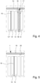
- Fig. 4 and 5 schematically show test setups or test arrangements for carrying out temperature measurements on proposed thermal insulation elements 1.
- thermal insulation function or capability of the proposed thermal insulation elements 1 was investigated.
- heat was introduced into the housing 9 or a comparable structure via a heating element 16, preferably a heating foil, in order to simulate comparable temperature conditions as in the case of uncontrolled heat development or thermal runaway.
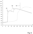
- the resulting temperature diagrams or temperature profiles are shown in Fig. 6 for a thermal insulation element 1 with a first layer structure and in Fig. 7 for a thermal insulation element 1 with a second layer structure.
- the heating element 16 was introduced between a battery cell 12' - located at a second location starting from the thermal insulation element 1 - and a battery cell 12" - located at a third location starting from the thermal insulation element 1 - and continuously heated to a temperature above 120 °C, preferably above 200 °C.
- the resulting temperature profile or temperature rise on the thermal insulation element 1 was measured on a cold side 17 facing away from the heating element 16 on the one hand and a hot side 18 facing the heating element 16 on the other hand using a measuring device, in particular a thermocouple, with two measurements being carried out for each layer structure.
- the curves M1 and M2 in Fig. 6 show for each measurement the resulting temperature curve on the cold side 17 of the thermal insulation element 1 with the first layer structure and the curves M1 and M2 in Fig. 7 corresponding temperature curves for a thermal insulation element 1 with a different or second layer structure.
- the Fig. 4 The thermal insulation function with regard to the containment or delay of the spread of thermal energy to neighboring battery cells 12 within the housing 9 can be investigated or proven using the test setup shown.
- the second experimental setup according to Fig. 5 differs from the first test setup in that the temperature profile is determined on a thermal insulation element 1 running on the top of the battery cells 12. This is intended to investigate or prove the thermal insulation function or thermal insulation with respect to a space adjacent to the battery 8, in particular the vehicle interior 15.
- the heating element 16 in particular the heating foil, is arranged between adjacent battery cells 12 and heated to at least 120 °C, preferably at least 200 °C, to simulate uncontrolled heat development or thermal runaway.
- the temperature profile or the temperature increase was recorded by means of a measuring device, in particular a thermocouple, on the cold side 19 of the thermal insulation element 1 facing away from the heating element 16 on the one hand and on a hot side 20 of the thermal insulation element 1 facing the heating element 16 on the other hand.
- the curve M3 in Fig. 6 shows the resulting temperature curve on the cold side 19 of the thermal insulation element 1 with the first layer structure and the curve M3 in Fig. 7 the resulting temperature curve for the second layer structure.
- a thermal insulation element 1 with the following first layer structure was used: Name/Designation Preferred training Preferred thickness First Top Layer 2 aluminum foil 50 ⁇ m fiber layer 5 Consolidated glass fiber needle felt 3 mm Second Top Layer 3 mica paper layer 0.5 mm overall structure approx. 5mm ( ⁇ 2mm during installation)
- the X-axis represents the time course in minutes. The axis starts with "0", which marks the starting point of switching on the heating foil 16.
- the Y-axis represents the temperature in °C.
- the curves start at just over 20°C, which is essentially ambient temperature.
- the temperature on the cold side 17 or 19 should be below 120°C, in particular below 80°C, for as long as possible in order to avoid damage or a short circuit and/or to prevent complete destruction or explosion of the battery 8, in particular in order to protect the vehicle interior 15 for a sufficiently long time from the release of heat, gases and/or fragments.
- curves M1 and M2 differ only slightly from each other, as they are two measurements from the same series of measurements (test setup Fig. 4 ).
- curve M3 (test setup Fig. 5 ) on the one hand with the curves M1 and M2 (test setup Fig. 4 ) on the other hand shows that the highest temperature (115.4 °C) was measured on the cold side 19. However, this temperature is only reached after more than 30 minutes - and thus significantly later than with the other curves M1 and M2. Until about 25 minutes after the introduction of heat, curve M3 runs significantly below the other two curves M1 and M2 and only rises This enables efficient thermal insulation on the cold side 19, particularly in the first 20 to 25 minutes, and thus high thermal protection against an adjacent room or vehicle interior 15 on the upper side.
- results show that the spread of heat or thermal runaway to neighboring battery cells 12 is efficiently delayed or contained, since the maximum limit temperature of 120 °C is not reached in all curves M1 to M3. This eliminates or at least minimizes the risk of damage or short circuits.
- the first layer structure can be realized comparatively cost-effectively.
- a proposed thermal insulation element 1 with the following second layer structure was used: name/designation Preferred training Preferred thickness First Top Layer 2 aluminum foil 50 ⁇ m fiber layer 5 Solidified glass fleece 5 mm intermediate layer 6 polyimide film 25 ⁇ m fiber layer 5 Solidified glass fleece 5 mm Second Top Layer 3 mica paper layer 0.2 mm overall structure approx. 10mm ( ⁇ 3mm during installation)
- the X-axis represents the time course in minutes.
- the axis starts with "0", which is the starting point of switching on the heating foils 14 and 15 to initiate the heat development in the corresponding groups of battery cells 12A-E (see Fig. 5 ) begins.
- the Y-axis represents the temperature in °C.
- the curves start at just over 20°C, which is essentially ambient temperature.
- the highest temperature for all measurements was 76.5 °C on curve M1 (i.e. on the cold side 17 during the first measurement, Fig. 4 ) after 10 minutes.
- the maximum temperature on the opposite hot side 18 was 1300 °C.
- the preferred maximum limit temperature of 80°C was not reached in all cases, so that accelerated ageing of the adjacent battery cell was avoided or at least reduced.
- curve M3 (test setup Fig. 5 ) on the one hand with the curves M1 and M2 (test setup Fig. 4 ) on the other hand shows that not only the lowest maximum temperature (70 °C) is present on the cold side 19 (curve M3), but this maximum temperature also occurs much later, namely after about 55 minutes. Nevertheless, the lowest temperature (730 °C) was also measured on the corresponding hot side 20.
- Fig. 7 It can be seen that in the second layer structure a significant temperature increase in one of the curves M1 to M3 is only observed after a time T of about 11 to 12 minutes.
- the Fig. 6 The course explained confirms that on the cold side 19, especially in the first minutes of heat introduction - in Fig. 7 until after about 45 minutes - there is a significantly lower temperature compared to the cold side 17 (curves M1 and M2).
- the thermal insulation element 1 with the second layer structure enables particularly effective thermal insulation compared to adjacent rooms or areas, in particular the vehicle interior 15.
- a comparison of curves M1 to M3 of Fig. 7 (second layer structure) with the corresponding curves of Fig. 6 (first layer structure) also shows that a further improved thermal insulation function can be achieved with the second layer structure.
- a reduction in the maximum temperatures was achieved, with the difference in curves M3 (first layer structure: 115.4 °C compared to the second layer structure: 70.0 °C) being particularly significant. This proves the particularly advantageous use of the second layer structure as top-side thermal insulation.
- the second layer structure allows an optimal reduction of the heat transfer and thus a particularly efficient thermal insulation function due to the multilayer structure of the intermediate layer 4, in particular with the polyimide layer arranged therein as intermediate layer 6.
- the polyimide layer protected by the nonwoven fabric retains its structure even after thermal explosion, so that the electrical insulation is maintained.
- the tests show that the proposed thermal insulation element 1 is suitable both for containing heat within the battery 8 and for top-side arrangement or insulation, i.e. in particular for thermal protection of adjacent vehicle interiors 15.
- the efficiency is optimal with the second layer composite, whereby the first layer composite allows a comparatively cost-effective implementation while also providing effective thermal insulation.
- the present invention further relates to the use of the proposed thermal insulation element 1 on and/or in a battery 8, preferably a lithium-ion battery, in particular a traction battery for an electric vehicle.
- a battery 8 preferably a lithium-ion battery, in particular a traction battery for an electric vehicle.
- a thermal insulation element 1 is arranged on top of the housing 9 in order to enable thermal insulation on the top.
- a thermal insulation element 1 is arranged for thermal insulation between two adjacent battery cells 12.
- the thermal insulation element 1 is attached or fastened, preferably glued, to a housing cover 11 or upper housing part of the housing 9.
- the thermal insulation element 1 is attached, in particular over its entire surface, to an inner side 13 of the housing cover 11 facing the housing interior.
- the thermal insulation element 1 is mounted or aligned transversely or perpendicularly to the inner side 13.
- At least one first thermal insulation element 1A and at least one second thermal insulation element 1B are used, wherein the first thermal insulation element 1A closes or thermally insulates the housing interior on the top and the second thermal insulation element 1B is arranged between adjacent battery cells 12A-E.
- the second thermal insulation element 1B is attached, in particular transversely or vertically, to the first thermal insulation element 1A, preferably glued, needled or welded.
Landscapes
- Chemical & Material Sciences (AREA)
- Chemical Kinetics & Catalysis (AREA)
- Electrochemistry (AREA)
- General Chemical & Material Sciences (AREA)
- Engineering & Computer Science (AREA)
- Manufacturing & Machinery (AREA)
- General Engineering & Computer Science (AREA)
- Mechanical Engineering (AREA)
- Secondary Cells (AREA)
- Laminated Bodies (AREA)
- Battery Mounting, Suspending (AREA)
- Gas Exhaust Devices For Batteries (AREA)
- Primary Cells (AREA)
Priority Applications (1)
| Application Number | Priority Date | Filing Date | Title |
|---|---|---|---|
| EP25158232.6A EP4539212A3 (de) | 2017-12-21 | 2018-12-18 | Batterie mit mehrschichtigem dämmelement und verwendung eines mehrschichten dämmelements zur thermischen isolierung einer batterie |
Applications Claiming Priority (3)
| Application Number | Priority Date | Filing Date | Title |
|---|---|---|---|
| DE102017011886 | 2017-12-21 | ||
| DE102018000421.0A DE102018000421A1 (de) | 2017-12-21 | 2018-01-19 | Mehrschichtiges Wärmedämmelement für Batterien |
| PCT/EP2018/085432 WO2019121641A1 (de) | 2017-12-21 | 2018-12-18 | Mehrschichtiges wärmedämmelement für batterien |
Related Child Applications (1)
| Application Number | Title | Priority Date | Filing Date |
|---|---|---|---|
| EP25158232.6A Division EP4539212A3 (de) | 2017-12-21 | 2018-12-18 | Batterie mit mehrschichtigem dämmelement und verwendung eines mehrschichten dämmelements zur thermischen isolierung einer batterie |
Publications (3)
| Publication Number | Publication Date |
|---|---|
| EP3729536A1 EP3729536A1 (de) | 2020-10-28 |
| EP3729536C0 EP3729536C0 (de) | 2025-02-26 |
| EP3729536B1 true EP3729536B1 (de) | 2025-02-26 |
Family
ID=66768734
Family Applications (2)
| Application Number | Title | Priority Date | Filing Date |
|---|---|---|---|
| EP18842771.0A Active EP3729536B1 (de) | 2017-12-21 | 2018-12-18 | Batterie mit einem mehrschichtigen wärmedämmelement |
| EP25158232.6A Pending EP4539212A3 (de) | 2017-12-21 | 2018-12-18 | Batterie mit mehrschichtigem dämmelement und verwendung eines mehrschichten dämmelements zur thermischen isolierung einer batterie |
Family Applications After (1)
| Application Number | Title | Priority Date | Filing Date |
|---|---|---|---|
| EP25158232.6A Pending EP4539212A3 (de) | 2017-12-21 | 2018-12-18 | Batterie mit mehrschichtigem dämmelement und verwendung eines mehrschichten dämmelements zur thermischen isolierung einer batterie |
Country Status (9)
| Country | Link |
|---|---|
| US (3) | US11664546B2 (enExample) |
| EP (2) | EP3729536B1 (enExample) |
| JP (3) | JP7373488B2 (enExample) |
| KR (2) | KR20250107954A (enExample) |
| CN (1) | CN111512464A (enExample) |
| DE (1) | DE102018000421A1 (enExample) |
| ES (1) | ES3025839T3 (enExample) |
| PL (1) | PL3729536T3 (enExample) |
| WO (1) | WO2019121641A1 (enExample) |
Families Citing this family (102)
| Publication number | Priority date | Publication date | Assignee | Title |
|---|---|---|---|---|
| DE102018000421A1 (de) | 2017-12-21 | 2019-06-27 | H.K.O. Isolier- Und Textiltechnik Gmbh | Mehrschichtiges Wärmedämmelement für Batterien |
| WO2020070275A1 (de) | 2018-10-05 | 2020-04-09 | Cuylits Holding GmbH | Brandschutzvorrichtung mit verbundsystem, verbundsystem und batterie-pack mit brandschutzvorrichtung |
| WO2021061516A1 (en) * | 2019-09-23 | 2021-04-01 | Mitsubishi Chemical America, Inc. | Heat resistant fiber layer for battery insulation |
| KR102792385B1 (ko) * | 2019-10-18 | 2025-04-04 | 주식회사 엘지에너지솔루션 | 배터리 팩 및 이러한 배터리 팩을 포함하는 자동차 |
| EP3832749B1 (en) * | 2019-12-06 | 2025-10-08 | Autoneum Management AG | Exterior thermal battery-cover |
| CN110951230B (zh) * | 2019-12-10 | 2022-02-08 | 万奔电子科技股份有限公司 | 一种光伏逆变器电源多层板及其制备工艺 |
| CN111180752A (zh) * | 2019-12-18 | 2020-05-19 | 安徽正熹标王新能源有限公司 | 一种耐高温锌锰电池 |
| DE102020200006A1 (de) * | 2020-01-02 | 2021-07-08 | Volkswagen Aktiengesellschaft | Fahrzeugbatterie |
| CN114946075A (zh) * | 2020-01-10 | 2022-08-26 | H.K.O.绝缘-纺织技术股份有限公司 | 用于电池的多层保护元件 |
| CN113386589A (zh) * | 2020-03-11 | 2021-09-14 | 华晨宝马汽车有限公司 | 用于电动汽车电池的上部防护件 |
| CN115244747A (zh) * | 2020-03-12 | 2022-10-25 | 罗杰斯公司 | 用于电池的热管理多层片 |
| DE102020117546A1 (de) | 2020-07-03 | 2022-01-05 | Bayerische Motoren Werke Aktiengesellschaft | Schutzvorrichtung für Batteriezellen |
| CN116075969A (zh) * | 2020-07-10 | 2023-05-05 | 波拉里尔姆能源解决方案公司 | 包括阻燃包封件的电池设备 |
| KR102881339B1 (ko) * | 2020-09-02 | 2025-11-07 | 에스케이온 주식회사 | 열 차단막이 내장된 고전압 배터리 모듈 및 팩 |
| KR20220053251A (ko) * | 2020-10-22 | 2022-04-29 | 주식회사 엘지에너지솔루션 | 전지 모듈 및 이를 포함하는 전지 팩 |
| DE102020128576B3 (de) * | 2020-10-30 | 2022-01-05 | Bayerische Motoren Werke Aktiengesellschaft | Gegen thermisches Durchgehen resistente Batterieeinrichtung und Kraftfahrzeug |
| BE1028766B1 (nl) * | 2020-11-02 | 2022-05-30 | Bebat Vzw | Container voor het transport en/of de opslag van batterijen en het gebruik van een dergelijke container |
| DE102020007327A1 (de) | 2020-12-01 | 2022-06-02 | H.K.O. Isolier- Und Textiltechnik Gmbh | Mehrschichtiges Schutzelement für eine Batterie |
| WO2022124598A1 (ko) * | 2020-12-07 | 2022-06-16 | 주식회사 엘지에너지솔루션 | 전지 모듈 및 이를 포함하는 전지 팩 |
| US20230299403A1 (en) * | 2020-12-14 | 2023-09-21 | Maftec Co., Ltd. | Battery pack cover, battery pack unit and electric mobility |
| DE102020133450A1 (de) * | 2020-12-15 | 2022-06-15 | Bayerische Motoren Werke Aktiengesellschaft | Thermisch robuste zellanordnung und zellmodul mit einer solchen zellanordnung |
| DE102020216383A1 (de) | 2020-12-21 | 2022-06-23 | Volkswagen Aktiengesellschaft | Batteriezellenmodul und Batterie |
| CN117121273A (zh) * | 2020-12-23 | 2023-11-24 | 3M创新有限公司 | 电池模块及其制造方法 |
| JP7552376B2 (ja) * | 2021-01-20 | 2024-09-18 | スズキ株式会社 | 電装部品の断熱構造 |
| DE102021202163A1 (de) | 2021-03-05 | 2022-09-08 | Commeo Gmbh | Akkumulatormodul |
| DE102021105935A1 (de) * | 2021-03-11 | 2022-09-15 | Volkswagen Aktiengesellschaft | Batterieanordnung |
| JP7670515B2 (ja) * | 2021-03-15 | 2025-04-30 | イビデン株式会社 | 組電池用熱制御シート及び組電池 |
| JP7670514B2 (ja) * | 2021-03-15 | 2025-04-30 | イビデン株式会社 | 組電池用熱制御シート及び組電池 |
| JP7670516B2 (ja) * | 2021-03-15 | 2025-04-30 | イビデン株式会社 | 組電池用熱制御シート及び組電池 |
| JP7670513B2 (ja) * | 2021-03-15 | 2025-04-30 | イビデン株式会社 | 組電池用熱制御シート及び組電池 |
| JP7670525B2 (ja) * | 2021-03-25 | 2025-04-30 | イビデン株式会社 | 組電池用熱制御シート及び組電池 |
| WO2022199642A1 (zh) * | 2021-03-25 | 2022-09-29 | 东丽纤维研究所(中国)有限公司 | 一种耐火焰毡 |
| JP7700235B2 (ja) * | 2021-03-31 | 2025-06-30 | 香港時代新能源科技有限公司 | 電池の筐体、電池、電力消費装置、電池の製造方法と装置 |
| KR102883559B1 (ko) * | 2021-04-13 | 2025-11-10 | 주식회사 엘지에너지솔루션 | 배터리 팩 |
| US11688904B2 (en) * | 2021-04-13 | 2023-06-27 | GM Global Technology Operations LLC | Electric powertrain system with multi-module battery pack and intermodule thermal barrier |
| EP4098436A1 (en) * | 2021-06-02 | 2022-12-07 | h.k.o. Isolier- und Textiltechnik GmbH | Multi-layer protective element of a battery |
| KR102641941B1 (ko) * | 2021-07-02 | 2024-02-27 | 아스펜 에어로겔, 인코포레이티드 | 배터리 기반 에너지 저장 시스템에서 열 전파를 완화하기 위한 시스템 및 방법 |
| BR112023018624A2 (pt) * | 2021-07-02 | 2024-01-23 | Aspen Aerogels Inc | Materiais, sistemas e métodos para encapsular materiais de barreira térmica |
| EP4324046A2 (en) | 2021-07-02 | 2024-02-21 | Aspen Aerogels Inc. | Devices, systems, and methods for controlling vent gases and ejecta from thermal runaway events in energy storage systems |
| DE102021207402A1 (de) | 2021-07-13 | 2023-01-19 | Volkswagen Aktiengesellschaft | Hochvoltbatteriesystem |
| DE102021118395A1 (de) | 2021-07-15 | 2023-01-19 | Audi Aktiengesellschaft | Batterieanordnung mit Brandschutzeinrichtung und Kraftfahrzeug |
| JP2024529915A (ja) * | 2021-07-19 | 2024-08-14 | フェデラル-モーグル・パワートレイン・リミテッド・ライアビリティ・カンパニー | 電池パック用の熱および電気絶縁体 |
| DE102021121397A1 (de) | 2021-08-18 | 2023-02-23 | Dr. Ing. H.C. F. Porsche Aktiengesellschaft | Batterieanordnung |
| US20230093415A1 (en) * | 2021-09-21 | 2023-03-23 | Samsung Sdi Co., Ltd. | Method of manufacturing an electrically insulated conductor |
| EP4152480A1 (en) * | 2021-09-21 | 2023-03-22 | Samsung SDI Co., Ltd. | Method of manufacturing an electrically insulated conductor |
| DE102021005097A1 (de) * | 2021-10-12 | 2023-04-13 | Mercedes-Benz Group AG | Trennwandbaugruppe für ein Batteriegehäuse, Batterie und Fahrzeug |
| EP4167355A1 (en) * | 2021-10-15 | 2023-04-19 | Volvo Car Corporation | Battery cell pack for electric vehicle |
| KR20230064784A (ko) * | 2021-11-04 | 2023-05-11 | 주식회사 엘지에너지솔루션 | 전지 모듈 |
| WO2023090219A1 (ja) * | 2021-11-19 | 2023-05-25 | マフテック株式会社 | 無機繊維ブランケット、積層体、バッテリーパックユニット及び電動モビリティ |
| CN113823468B (zh) * | 2021-11-22 | 2022-02-15 | 浙江荣泰电工器材股份有限公司 | 一种低导热高绝缘云母件及成型工艺 |
| JP2023079703A (ja) * | 2021-11-29 | 2023-06-08 | イビデン株式会社 | 電池用熱拡散シート |
| CN114193851B (zh) * | 2021-12-02 | 2023-06-13 | 浙江荣泰电工器材股份有限公司 | 一种电芯之间的热防护复合件及其成型工艺 |
| DE102021132072A1 (de) * | 2021-12-06 | 2023-06-07 | Carl Freudenberg Kg | Energiespeichersystem |
| WO2023108099A1 (en) * | 2021-12-09 | 2023-06-15 | Federal-Mogul Powertrain Llc | Electric vehicle battery and battery cell interface material therefor |
| EP4199224B1 (en) * | 2021-12-17 | 2024-10-23 | EnerSys Delaware Inc. | Battery safety arrangement |
| EP4199223A1 (en) * | 2021-12-17 | 2023-06-21 | EnerSys Delaware Inc. | Metal ion battery safety arrangement |
| EP4199222B1 (en) * | 2021-12-17 | 2024-09-25 | EnerSys Delaware Inc. | Battery and safety arrangement |
| DE102021133796A1 (de) | 2021-12-20 | 2023-06-22 | Audi Aktiengesellschaft | Brandschutzhalbzeug für ein Kunststoffbauteil, insbesondere Unterfahrschutz, eines Kraftfahrzeugs, Herstellungsverfahren und Kraftfahrzeug |
| EP4201665A1 (de) | 2021-12-21 | 2023-06-28 | Nolax AG | Verbundmaterial als hitze-, brand- und/oder rauchschutzmaterial |
| KR102808650B1 (ko) * | 2021-12-23 | 2025-05-20 | 주식회사 엘지에너지솔루션 | 안전성이 강화된 배터리 모듈 |
| JP7772582B2 (ja) * | 2021-12-23 | 2025-11-18 | イビデン株式会社 | 電池用保護シート及び組電池モジュール |
| KR102577201B1 (ko) | 2022-01-14 | 2023-09-14 | 에스케이온 주식회사 | 배터리 모듈 및 배터리 팩 |
| WO2023164547A2 (en) * | 2022-02-24 | 2023-08-31 | Unifrax I Llc | Fiber-containing fire protection material |
| JP7513647B2 (ja) | 2022-03-22 | 2024-07-09 | イビデン株式会社 | 防炎材及びその製造方法、並びに電池モジュール |
| CN114937802B (zh) * | 2022-05-06 | 2023-04-28 | 苏州市华盛源机电有限公司 | 基于新材料的新能源客车电池包制造方法及其层压装置 |
| KR20230168498A (ko) * | 2022-06-07 | 2023-12-14 | 에스케이온 주식회사 | 배터리 모듈 |
| KR20240011380A (ko) * | 2022-07-19 | 2024-01-26 | 주식회사 엘지에너지솔루션 | 전지 팩 및 이를 포함하는 디바이스 |
| US20240030544A1 (en) * | 2022-07-21 | 2024-01-25 | Canoo Technologies Inc. | Mitigating thermal runaway of lithium-ion batteries |
| CN115117519A (zh) * | 2022-07-26 | 2022-09-27 | 巩义市泛锐熠辉复合材料有限公司 | 一种电池用热防护材料及其制备方法 |
| KR20240031474A (ko) * | 2022-08-29 | 2024-03-08 | 주식회사 엘지에너지솔루션 | 안전성이 향상된 배터리 팩 |
| WO2024049679A1 (en) * | 2022-09-01 | 2024-03-07 | Skybell Technologies Ip, Llc | External power systems for outdoor security systems |
| DE102022125582A1 (de) | 2022-10-05 | 2024-04-11 | Dr. Ing. H.C. F. Porsche Aktiengesellschaft | Batteriesystem mit verbesserten Brandschutzeigenschaften |
| KR20240051051A (ko) | 2022-10-11 | 2024-04-19 | 쿠일리츠 홀딩 게엠베하 | 복합 시스템을 구비한 방화 장치, 복합 시스템 및 방화 장치를 구비한 배터리 팩 |
| US20240154228A1 (en) * | 2022-11-03 | 2024-05-09 | Proterra Operating Company, Inc. | Composite battery pack wall with mica inner layer |
| EP4383421A1 (en) * | 2022-12-08 | 2024-06-12 | Abb Schweiz Ag | Battery cabinet for accommodating one or more battery modules, battery pack, and battery system |
| EP4391128A1 (en) * | 2022-12-22 | 2024-06-26 | Henkel AG & Co. KGaA | Multilayer protective element for a battery assembly comprising at least two battery cells |
| EP4462553A4 (en) * | 2022-12-23 | 2025-08-13 | Lg Energy Solution Ltd | BATTERY PACK AND VEHICLE COMPRISING IT |
| KR102660377B1 (ko) * | 2023-02-05 | 2024-04-24 | 주식회사 보백씨엔에스 | 마이카를 이용한 절연시트의 제조방법 및 위 제조방법에 의해 제조되는 마이카 절연시트 |
| KR20240123180A (ko) * | 2023-02-06 | 2024-08-13 | 주식회사 엘지에너지솔루션 | 배터리 팩 |
| DE102023103668A1 (de) * | 2023-02-15 | 2024-08-22 | Wpx Faserkeramik Gmbh | Batteriegehäusedeckel mit einem Abschnitt umfassend einen Faserverbund mit oxidischer Matrix |
| DE102023103675A1 (de) * | 2023-02-15 | 2024-08-22 | Wpx Faserkeramik Gmbh | Batteriegehausedeckel mit Faserverbund mit oxidischer Matrix |
| US20240297410A1 (en) * | 2023-03-01 | 2024-09-05 | Ford Global Technologies, Llc | Electrified vehicle with battery pack having separator with aperture arrangement |
| KR102540412B1 (ko) * | 2023-03-13 | 2023-06-08 | 주식회사 익성 | 탄소섬유 복합소재 및 이의 제조방법 |
| WO2024204375A1 (ja) * | 2023-03-29 | 2024-10-03 | イビデン株式会社 | 熱伝達抑制シート及びその製造方法、並びに電池モジュール |
| KR20240147149A (ko) * | 2023-03-31 | 2024-10-08 | 현대모비스 주식회사 | 내화성 및 열확산성이 개선된 복합마이카 단열패드를 포함하는 배터리 모듈 |
| CN116442609B (zh) * | 2023-04-21 | 2025-07-11 | 固德电材系统(苏州)股份有限公司 | 一种隔热材料及其制备方法和应用 |
| EP4468486A1 (en) | 2023-05-22 | 2024-11-27 | Saint-Gobain Adfors | Protection element and battery |
| WO2024253013A1 (ja) * | 2023-06-07 | 2024-12-12 | 株式会社Aescジャパン | 電池パック |
| EP4480695A1 (en) | 2023-06-19 | 2024-12-25 | Saint-Gobain Adfors SA | Insulation element |
| GB2631725A (en) * | 2023-07-11 | 2025-01-15 | Rolls Royce Plc | A battery pack |
| WO2025072662A1 (en) * | 2023-09-29 | 2025-04-03 | Federal-Mogul Powertrain Llc | Multilayer battery pack insulator |
| WO2025095130A1 (ja) * | 2023-11-02 | 2025-05-08 | 三菱ケミカル株式会社 | 組電池及びスペーサ |
| WO2025102049A1 (en) * | 2023-11-09 | 2025-05-15 | Fisker Ip/Austria Assets Trust | Multi-layer thermal insulation blanket for batteries |
| WO2025115369A1 (ja) * | 2023-11-29 | 2025-06-05 | イビデン株式会社 | 電池パック |
| US20250202004A1 (en) * | 2023-12-14 | 2025-06-19 | Federal-Mogul Powertrain Llc | Multilayer battery pack insulator and method of construction thereof |
| DE102024101646A1 (de) * | 2024-01-19 | 2025-07-24 | Elringklinger Ag | Schutzelement zur Anordnung an oder in einer Vorrichtung sowie Vorrichtung mit einem Schutzelement |
| WO2025173740A1 (ja) * | 2024-02-14 | 2025-08-21 | マフテック株式会社 | 延焼防止シート及び延焼防止カバー |
| KR20250137885A (ko) * | 2024-03-12 | 2025-09-19 | 삼성에스디아이 주식회사 | 배터리 모듈 및 배터리 팩 |
| JP2025144979A (ja) | 2024-03-21 | 2025-10-03 | トヨタ自動車株式会社 | 車両 |
| CN118040185B (zh) * | 2024-04-11 | 2024-07-19 | 珠海钜能新能源有限公司 | 微型电池及微型电池制备方法 |
| CN222654235U (zh) * | 2024-04-30 | 2025-03-21 | 惠州亿纬锂能股份有限公司 | 一种电池包 |
| KR20250161225A (ko) * | 2024-05-08 | 2025-11-17 | 주식회사 엘지에너지솔루션 | 배터리 장치 |
Citations (1)
| Publication number | Priority date | Publication date | Assignee | Title |
|---|---|---|---|---|
| US20060068278A1 (en) * | 2003-01-04 | 2006-03-30 | Bloom Richard L | Vehicle battery pack insulator |
Family Cites Families (59)
| Publication number | Priority date | Publication date | Assignee | Title |
|---|---|---|---|---|
| DE621613C (de) * | 1933-01-11 | 1935-11-11 | Oscar Gossler Glasgespinst Fab | Waermeschutzkoerper |
| JPS557428A (en) * | 1978-06-30 | 1980-01-19 | Yuasa Battery Co Ltd | Multilayer heat insulator |
| EP0090191B1 (de) * | 1982-03-27 | 1986-08-13 | BROWN, BOVERI & CIE Aktiengesellschaft | Thermische Isolierung |
| DE3242900A1 (de) * | 1982-03-27 | 1983-09-29 | Brown, Boveri & Cie Ag, 6800 Mannheim | Thermische isolierung |
| DE3219506A1 (de) | 1982-05-25 | 1983-12-01 | Brown, Boveri & Cie Ag, 6800 Mannheim | Thermische isolierung |
| JPS61175094A (ja) * | 1985-01-31 | 1986-08-06 | セーラー万年筆株式会社 | シヤープペンシル用芯の製造方法 |
| DE3802322A1 (de) * | 1986-08-28 | 1989-08-10 | Pelz Ernst Erpe Vertrieb | Verfahren zum herstellen eines verkleidungsteiles mit mindestens einer glasfaservlieslage |
| US6551951B1 (en) * | 1999-03-19 | 2003-04-22 | Johns Manville International, Inc. | Burn through resistant nonwoven mat, barrier, and insulation system |
| ES2227217T3 (es) | 2000-06-21 | 2005-04-01 | Compagnie Royale Asturienne Des Mines, Societe Anonyme | Barrera de proteccion. |
| US6670291B1 (en) | 2000-10-18 | 2003-12-30 | 3M Innovative Properties Company | Laminate sheet material for fire barrier applications |
| JP2002339217A (ja) * | 2001-05-09 | 2002-11-27 | Kanebo Ltd | 断熱材 |
| DE10134145B4 (de) | 2001-07-13 | 2015-05-28 | Daimler Ag | Feuerhemmendes Batteriegehäuse |
| JP2006195104A (ja) * | 2005-01-13 | 2006-07-27 | Yuuhou:Kk | 難燃性吸音断熱材 |
| US7901752B2 (en) * | 2006-06-16 | 2011-03-08 | Albany International Corp. | Advanced battery paster belt |
| DE102007032431A1 (de) * | 2006-07-11 | 2008-01-17 | H.K.O. Isolier- Und Textiltechnik Gmbh | Aufbau zur Wärmeisolierung |
| JP5157338B2 (ja) | 2006-09-21 | 2013-03-06 | 大日本印刷株式会社 | 扁平型電気化学セル金属端子部密封用接着性シート |
| JP4713566B2 (ja) * | 2007-12-28 | 2011-06-29 | シャープ株式会社 | 真空断熱材用芯材、真空断熱材、および、これらの製造方法 |
| EP2090470A1 (de) * | 2008-02-13 | 2009-08-19 | Frenzelit-Werke GmbH & Co. KG | Schallschutz-Abschirmung für den Motoren-, Unterboden-und Karosseriebereich von Kraftfahrzeugen und anderen Fahrzeugen |
| JP5269200B2 (ja) * | 2009-06-08 | 2013-08-21 | パナソニック株式会社 | 電池パック |
| US8541126B2 (en) | 2009-08-31 | 2013-09-24 | Tesla Motors, Inc. | Thermal barrier structure for containing thermal runaway propagation within a battery pack |
| DE102009052508A1 (de) | 2009-11-11 | 2011-05-12 | Carl Freudenberg Kg | Mechanisch flexibles und poröses Ausgleichselement zur Temperierung elektrochemischer Zellen |
| TWI408053B (zh) | 2009-12-21 | 2013-09-11 | Saint Gobain Performance Plast | 熱傳導性發泡體材料 |
| TWI419391B (zh) | 2009-12-25 | 2013-12-11 | Ind Tech Res Inst | 電池系統中的散熱與熱失控擴散防護結構 |
| DE202010017454U1 (de) * | 2010-12-07 | 2012-01-04 | Lydall Gerhardi Gmbh & Co.Kg | Vorrichtung zur thermischen Isolation einer Batterie |
| EP2626200A1 (de) | 2012-02-08 | 2013-08-14 | Quadrant Plastic Composites AG | Flächiger Verbundwerkstoff |
| DK177775B1 (en) * | 2012-04-20 | 2014-06-23 | Rockwool Int | Insulation system for covering a facade of a building |
| CN103510670A (zh) * | 2012-06-18 | 2014-01-15 | 丁召志 | 具有高等级防火耐雨淋特性的轻体水泥保温装饰板 |
| CN202782015U (zh) * | 2012-09-30 | 2013-03-13 | 浙江联洋复合材料有限公司 | 汽车顶棚用针刺复合环保毡 |
| JP2014183013A (ja) * | 2013-03-21 | 2014-09-29 | Sumitomo Electric Ind Ltd | 電池パック |
| US9991481B2 (en) | 2013-05-29 | 2018-06-05 | Inoac Corporation | Thermal insulating cover |
| JP6233957B2 (ja) * | 2013-08-26 | 2017-11-22 | 槌屋ティスコ株式会社 | 積層シート、成形品及びその製造方法 |
| CN203503356U (zh) * | 2013-09-24 | 2014-03-26 | 河南开启电力实业有限公司 | 柔性防火电缆 |
| JP6506942B2 (ja) | 2014-10-23 | 2019-04-24 | 日東電工株式会社 | 断熱材およびバッテリーカバー |
| CN107004797B (zh) * | 2014-12-10 | 2020-05-19 | 松下知识产权经营株式会社 | 电池 |
| CN105133189B (zh) * | 2015-07-21 | 2017-04-19 | 绍兴文理学院元培学院 | 一种阻燃型汽车内饰吸音材料及其生产工艺 |
| EP3142166A1 (en) | 2015-09-11 | 2017-03-15 | Von Roll Schweiz AG | A compressible composite material useful in particular as a construction material for batteries |
| WO2017110681A1 (ja) | 2015-12-25 | 2017-06-29 | 日東電工株式会社 | シリコーン発泡シートおよびその製造方法 |
| CN105489965A (zh) * | 2015-12-29 | 2016-04-13 | 宁德时代新能源科技股份有限公司 | 动力电池模组 |
| CN106931278A (zh) * | 2015-12-31 | 2017-07-07 | 深圳市纳能科技有限公司 | 保温隔热套及隔热箱 |
| AT518161B1 (de) | 2016-02-19 | 2017-08-15 | Avl List Gmbh | Batterie |
| JP2017182898A (ja) * | 2016-03-28 | 2017-10-05 | 積水化学工業株式会社 | バッテリ |
| WO2017208952A1 (ja) * | 2016-06-01 | 2017-12-07 | ダイニック株式会社 | エアフィルタ材料 |
| EP3269540A1 (en) | 2016-07-15 | 2018-01-17 | Von Roll Schweiz AG | Compressible and flexible composite material useful in particular as a construction material for batteries |
| DE202018006837U1 (de) | 2017-02-08 | 2023-08-02 | Elkem Silicones USA Corp. | Sekundärbatterie-Pack mit verbessertem Thermomanagement |
| US20180309107A1 (en) | 2017-04-19 | 2018-10-25 | Unifrax I Llc | Insulation barrier for electrochemical battery and electrochemical battery including same |
| EP3707300A4 (en) | 2017-11-10 | 2021-07-21 | 3M Innovative Properties Company | THERMAL INSULATION AND RELATED PROCESSES |
| GB2568688C (en) | 2017-11-22 | 2023-10-25 | Morgan Korea Co Ltd | Materials for fire protection |
| CN107914428A (zh) | 2017-12-19 | 2018-04-17 | 深圳市德镒盟电子有限公司 | 一种新能源汽车动力电池用隔热防火材料 |
| DE102018000421A1 (de) | 2017-12-21 | 2019-06-27 | H.K.O. Isolier- Und Textiltechnik Gmbh | Mehrschichtiges Wärmedämmelement für Batterien |
| CN111566170A (zh) | 2018-01-03 | 2020-08-21 | 尤尼弗瑞克斯 I 有限责任公司 | 电及热保护涂料和包括其的电化学电池 |
| WO2020047846A1 (en) * | 2018-09-07 | 2020-03-12 | 3M Innovative Properties Company | Fire protection article and related methods |
| WO2020070275A1 (de) | 2018-10-05 | 2020-04-09 | Cuylits Holding GmbH | Brandschutzvorrichtung mit verbundsystem, verbundsystem und batterie-pack mit brandschutzvorrichtung |
| CN209822690U (zh) | 2019-07-11 | 2019-12-20 | 巩义市泛锐熠辉复合材料有限公司 | 一种新能源汽车电池组用气凝胶阻燃片 |
| KR102486895B1 (ko) | 2019-08-01 | 2023-01-10 | 쓰리엠 이노베이티브 프로퍼티즈 컴파니 | 재충전가능 전기 에너지 저장 시스템을 위한 열 장벽 재료 |
| WO2021019495A1 (en) | 2019-08-01 | 2021-02-04 | 3M Innovative Properties Company | Fire barriers for electric vehicle battery modules |
| CN110641101A (zh) | 2019-10-08 | 2020-01-03 | 3M材料技术(合肥)有限公司 | 隔热复合材料 |
| CN114946075A (zh) | 2020-01-10 | 2022-08-26 | H.K.O.绝缘-纺织技术股份有限公司 | 用于电池的多层保护元件 |
| DE102020007327A1 (de) | 2020-12-01 | 2022-06-02 | H.K.O. Isolier- Und Textiltechnik Gmbh | Mehrschichtiges Schutzelement für eine Batterie |
| EP4098436A1 (en) | 2021-06-02 | 2022-12-07 | h.k.o. Isolier- und Textiltechnik GmbH | Multi-layer protective element of a battery |
-
2018
- 2018-01-19 DE DE102018000421.0A patent/DE102018000421A1/de active Pending
- 2018-12-18 EP EP18842771.0A patent/EP3729536B1/de active Active
- 2018-12-18 JP JP2020535106A patent/JP7373488B2/ja active Active
- 2018-12-18 PL PL18842771.0T patent/PL3729536T3/pl unknown
- 2018-12-18 CN CN201880082648.4A patent/CN111512464A/zh active Pending
- 2018-12-18 WO PCT/EP2018/085432 patent/WO2019121641A1/de not_active Ceased
- 2018-12-18 ES ES18842771T patent/ES3025839T3/es active Active
- 2018-12-18 KR KR1020257021899A patent/KR20250107954A/ko active Pending
- 2018-12-18 EP EP25158232.6A patent/EP4539212A3/de active Pending
- 2018-12-18 US US16/771,906 patent/US11664546B2/en active Active
- 2018-12-18 KR KR1020207017164A patent/KR102829643B1/ko active Active
-
2023
- 2023-02-23 US US18/113,382 patent/US12095066B2/en active Active
- 2023-07-20 JP JP2023118240A patent/JP7557019B2/ja active Active
-
2024
- 2024-09-05 US US18/825,719 patent/US20240429491A1/en active Pending
- 2024-09-12 JP JP2024158110A patent/JP7716553B2/ja active Active
Patent Citations (1)
| Publication number | Priority date | Publication date | Assignee | Title |
|---|---|---|---|---|
| US20060068278A1 (en) * | 2003-01-04 | 2006-03-30 | Bloom Richard L | Vehicle battery pack insulator |
Also Published As
| Publication number | Publication date |
|---|---|
| CN111512464A (zh) | 2020-08-07 |
| JP7373488B2 (ja) | 2023-11-02 |
| PL3729536T3 (pl) | 2025-06-09 |
| EP4539212A2 (de) | 2025-04-16 |
| EP4539212A3 (de) | 2025-04-23 |
| DE102018000421A1 (de) | 2019-06-27 |
| JP7557019B2 (ja) | 2024-09-26 |
| US11664546B2 (en) | 2023-05-30 |
| EP3729536C0 (de) | 2025-02-26 |
| ES3025839T3 (en) | 2025-06-09 |
| KR102829643B1 (ko) | 2025-07-03 |
| KR20250107954A (ko) | 2025-07-14 |
| US12095066B2 (en) | 2024-09-17 |
| KR20200100639A (ko) | 2020-08-26 |
| US20240429491A1 (en) | 2024-12-26 |
| EP3729536A1 (de) | 2020-10-28 |
| US20230198051A1 (en) | 2023-06-22 |
| JP2025003985A (ja) | 2025-01-14 |
| US20210074960A1 (en) | 2021-03-11 |
| JP7716553B2 (ja) | 2025-07-31 |
| JP2023156325A (ja) | 2023-10-24 |
| WO2019121641A1 (de) | 2019-06-27 |
| JP2021507483A (ja) | 2021-02-22 |
Similar Documents
| Publication | Publication Date | Title |
|---|---|---|
| EP3729536B1 (de) | Batterie mit einem mehrschichtigen wärmedämmelement | |
| DE102021000029A1 (de) | Mehrschichtiges Schutzelement für eine Batterie | |
| DE102020007327A1 (de) | Mehrschichtiges Schutzelement für eine Batterie | |
| US20240274922A1 (en) | Multi-layer protective element of a battery | |
| EP3811431B1 (de) | Fahrzeug mit einem hochvoltspeicher | |
| DE202022002887U1 (de) | Systeme zur Abschwächung thermischer Propagation in batteriegestützten Energiespeicherungssystemen | |
| DE202022106977U1 (de) | Mechanische Barriereelemente mit Durchflusskühlung | |
| EP0164006A1 (de) | Wärmedämmformkörper mit Umhüllung | |
| DE202022002799U1 (de) | Materialien und Systeme zur Abschwächung elektrischer Energiespeicherungs-Wärmeereignisse | |
| DE102021124831A1 (de) | Batterieanordnung und Kraftfahrzeug | |
| DE102014008000B4 (de) | Akkumulatorvorrichtung | |
| DE102021100727A1 (de) | Elektrischer Energiespeicher | |
| DE102013220937A1 (de) | Thermische Entkopplung eines Energiespeichersystems | |
| DE202022104235U1 (de) | Batterieanordnung mit verbesserter thermischer und mechanischer Beständigkeit | |
| EP4480695A1 (en) | Insulation element | |
| DE202024102240U1 (de) | Batterieanordnung mit verbesserter thermischer Beständigkeit | |
| DE102017117769B4 (de) | Thermische Energie aufnehmende Schott-Wand-Vorrichtung | |
| WO2025228970A1 (de) | Batterieanordnung mit verbesserter thermischer isolierung | |
| DE102024112303A1 (de) | Batterieanordnung mit verbesserter thermischer Isolierung |
Legal Events
| Date | Code | Title | Description |
|---|---|---|---|
| STAA | Information on the status of an ep patent application or granted ep patent |
Free format text: STATUS: UNKNOWN |
|
| STAA | Information on the status of an ep patent application or granted ep patent |
Free format text: STATUS: THE INTERNATIONAL PUBLICATION HAS BEEN MADE |
|
| PUAI | Public reference made under article 153(3) epc to a published international application that has entered the european phase |
Free format text: ORIGINAL CODE: 0009012 |
|
| STAA | Information on the status of an ep patent application or granted ep patent |
Free format text: STATUS: REQUEST FOR EXAMINATION WAS MADE |
|
| 17P | Request for examination filed |
Effective date: 20200604 |
|
| AK | Designated contracting states |
Kind code of ref document: A1 Designated state(s): AL AT BE BG CH CY CZ DE DK EE ES FI FR GB GR HR HU IE IS IT LI LT LU LV MC MK MT NL NO PL PT RO RS SE SI SK SM TR |
|
| AX | Request for extension of the european patent |
Extension state: BA ME |
|
| DAV | Request for validation of the european patent (deleted) | ||
| DAX | Request for extension of the european patent (deleted) | ||
| STAA | Information on the status of an ep patent application or granted ep patent |
Free format text: STATUS: EXAMINATION IS IN PROGRESS |
|
| 17Q | First examination report despatched |
Effective date: 20210527 |
|
| TPAC | Observations filed by third parties |
Free format text: ORIGINAL CODE: EPIDOSNTIPA |
|
| TPAC | Observations filed by third parties |
Free format text: ORIGINAL CODE: EPIDOSNTIPA |
|
| TPAC | Observations filed by third parties |
Free format text: ORIGINAL CODE: EPIDOSNTIPA |
|
| REG | Reference to a national code |
Ref country code: DE Ref legal event code: R079 Free format text: PREVIOUS MAIN CLASS: H01M0002020000 Ipc: F16L0059080000 Ref document number: 502018015612 Country of ref document: DE |
|
| RIC1 | Information provided on ipc code assigned before grant |
Ipc: H01M 10/658 20140101ALI20241126BHEP Ipc: H01M 50/209 20210101ALI20241126BHEP Ipc: H01M 50/124 20210101ALI20241126BHEP Ipc: F16L 59/08 20060101AFI20241126BHEP |
|
| GRAP | Despatch of communication of intention to grant a patent |
Free format text: ORIGINAL CODE: EPIDOSNIGR1 |
|
| STAA | Information on the status of an ep patent application or granted ep patent |
Free format text: STATUS: GRANT OF PATENT IS INTENDED |
|
| GRAS | Grant fee paid |
Free format text: ORIGINAL CODE: EPIDOSNIGR3 |
|
| GRAA | (expected) grant |
Free format text: ORIGINAL CODE: 0009210 |
|
| STAA | Information on the status of an ep patent application or granted ep patent |
Free format text: STATUS: THE PATENT HAS BEEN GRANTED |
|
| INTG | Intention to grant announced |
Effective date: 20250114 |
|
| AK | Designated contracting states |
Kind code of ref document: B1 Designated state(s): AL AT BE BG CH CY CZ DE DK EE ES FI FR GB GR HR HU IE IS IT LI LT LU LV MC MK MT NL NO PL PT RO RS SE SI SK SM TR |
|
| REG | Reference to a national code |
Ref country code: GB Ref legal event code: FG4D Free format text: NOT ENGLISH |
|
| REG | Reference to a national code |
Ref country code: CH Ref legal event code: EP |
|
| REG | Reference to a national code |
Ref country code: DE Ref legal event code: R096 Ref document number: 502018015612 Country of ref document: DE |
|
| REG | Reference to a national code |
Ref country code: IE Ref legal event code: FG4D Free format text: LANGUAGE OF EP DOCUMENT: GERMAN |
|
| U01 | Request for unitary effect filed |
Effective date: 20250325 |
|
| U07 | Unitary effect registered |
Designated state(s): AT BE BG DE DK EE FI FR IT LT LU LV MT NL PT RO SE SI Effective date: 20250331 |
|
| REG | Reference to a national code |
Ref country code: ES Ref legal event code: FG2A Ref document number: 3025839 Country of ref document: ES Kind code of ref document: T3 Effective date: 20250609 |
|
| PG25 | Lapsed in a contracting state [announced via postgrant information from national office to epo] |
Ref country code: RS Free format text: LAPSE BECAUSE OF FAILURE TO SUBMIT A TRANSLATION OF THE DESCRIPTION OR TO PAY THE FEE WITHIN THE PRESCRIBED TIME-LIMIT Effective date: 20250526 |
|
| PG25 | Lapsed in a contracting state [announced via postgrant information from national office to epo] |
Ref country code: NO Free format text: LAPSE BECAUSE OF FAILURE TO SUBMIT A TRANSLATION OF THE DESCRIPTION OR TO PAY THE FEE WITHIN THE PRESCRIBED TIME-LIMIT Effective date: 20250526 Ref country code: IS Free format text: LAPSE BECAUSE OF FAILURE TO SUBMIT A TRANSLATION OF THE DESCRIPTION OR TO PAY THE FEE WITHIN THE PRESCRIBED TIME-LIMIT Effective date: 20250626 |
|
| PG25 | Lapsed in a contracting state [announced via postgrant information from national office to epo] |
Ref country code: HR Free format text: LAPSE BECAUSE OF FAILURE TO SUBMIT A TRANSLATION OF THE DESCRIPTION OR TO PAY THE FEE WITHIN THE PRESCRIBED TIME-LIMIT Effective date: 20250226 |
|
| PG25 | Lapsed in a contracting state [announced via postgrant information from national office to epo] |
Ref country code: GR Free format text: LAPSE BECAUSE OF FAILURE TO SUBMIT A TRANSLATION OF THE DESCRIPTION OR TO PAY THE FEE WITHIN THE PRESCRIBED TIME-LIMIT Effective date: 20250527 |
|
| PG25 | Lapsed in a contracting state [announced via postgrant information from national office to epo] |
Ref country code: SM Free format text: LAPSE BECAUSE OF FAILURE TO SUBMIT A TRANSLATION OF THE DESCRIPTION OR TO PAY THE FEE WITHIN THE PRESCRIBED TIME-LIMIT Effective date: 20250226 |
|
| PG25 | Lapsed in a contracting state [announced via postgrant information from national office to epo] |
Ref country code: CZ Free format text: LAPSE BECAUSE OF FAILURE TO SUBMIT A TRANSLATION OF THE DESCRIPTION OR TO PAY THE FEE WITHIN THE PRESCRIBED TIME-LIMIT Effective date: 20250226 |
|
| PG25 | Lapsed in a contracting state [announced via postgrant information from national office to epo] |
Ref country code: SK Free format text: LAPSE BECAUSE OF FAILURE TO SUBMIT A TRANSLATION OF THE DESCRIPTION OR TO PAY THE FEE WITHIN THE PRESCRIBED TIME-LIMIT Effective date: 20250226 |
|
| U20 | Renewal fee for the european patent with unitary effect paid |
Year of fee payment: 8 Effective date: 20251110 |