EP3715166B1 - Struktur für operativen abschnitt eines fahrzeugs - Google Patents
Struktur für operativen abschnitt eines fahrzeugs Download PDFInfo
- Publication number
- EP3715166B1 EP3715166B1 EP20175663.2A EP20175663A EP3715166B1 EP 3715166 B1 EP3715166 B1 EP 3715166B1 EP 20175663 A EP20175663 A EP 20175663A EP 3715166 B1 EP3715166 B1 EP 3715166B1
- Authority
- EP
- European Patent Office
- Prior art keywords
- operational
- rest
- palm
- palm rest
- audio
- Prior art date
- Legal status (The legal status is an assumption and is not a legal conclusion. Google has not performed a legal analysis and makes no representation as to the accuracy of the status listed.)
- Not-in-force
Links
Images





Classifications
-
- B—PERFORMING OPERATIONS; TRANSPORTING
- B60—VEHICLES IN GENERAL
- B60R—VEHICLES, VEHICLE FITTINGS, OR VEHICLE PARTS, NOT OTHERWISE PROVIDED FOR
- B60R11/00—Arrangements for holding or mounting articles, not otherwise provided for
- B60R11/02—Arrangements for holding or mounting articles, not otherwise provided for for radio sets, television sets, telephones, or the like; Arrangement of controls thereof
- B60R11/0264—Arrangements for holding or mounting articles, not otherwise provided for for radio sets, television sets, telephones, or the like; Arrangement of controls thereof for control means
-
- B—PERFORMING OPERATIONS; TRANSPORTING
- B60—VEHICLES IN GENERAL
- B60N—SEATS SPECIALLY ADAPTED FOR VEHICLES; VEHICLE PASSENGER ACCOMMODATION NOT OTHERWISE PROVIDED FOR
- B60N2/00—Seats specially adapted for vehicles; Arrangement or mounting of seats in vehicles
- B60N2/75—Arm-rests
- B60N2/79—Adaptations for additional use of the arm-rests
- B60N2/797—Adaptations for additional use of the arm-rests for use as electrical control means, e.g. switches
-
- B—PERFORMING OPERATIONS; TRANSPORTING
- B60—VEHICLES IN GENERAL
- B60K—ARRANGEMENT OR MOUNTING OF PROPULSION UNITS OR OF TRANSMISSIONS IN VEHICLES; ARRANGEMENT OR MOUNTING OF PLURAL DIVERSE PRIME-MOVERS IN VEHICLES; AUXILIARY DRIVES FOR VEHICLES; INSTRUMENTATION OR DASHBOARDS FOR VEHICLES; ARRANGEMENTS IN CONNECTION WITH COOLING, AIR INTAKE, GAS EXHAUST OR FUEL SUPPLY OF PROPULSION UNITS IN VEHICLES
- B60K35/00—Instruments specially adapted for vehicles; Arrangement of instruments in or on vehicles
- B60K35/10—Input arrangements, i.e. from user to vehicle, associated with vehicle functions or specially adapted therefor
-
- B—PERFORMING OPERATIONS; TRANSPORTING
- B60—VEHICLES IN GENERAL
- B60K—ARRANGEMENT OR MOUNTING OF PROPULSION UNITS OR OF TRANSMISSIONS IN VEHICLES; ARRANGEMENT OR MOUNTING OF PLURAL DIVERSE PRIME-MOVERS IN VEHICLES; AUXILIARY DRIVES FOR VEHICLES; INSTRUMENTATION OR DASHBOARDS FOR VEHICLES; ARRANGEMENTS IN CONNECTION WITH COOLING, AIR INTAKE, GAS EXHAUST OR FUEL SUPPLY OF PROPULSION UNITS IN VEHICLES
- B60K35/00—Instruments specially adapted for vehicles; Arrangement of instruments in or on vehicles
- B60K35/60—Instruments characterised by their location or relative disposition in or on vehicles
-
- B—PERFORMING OPERATIONS; TRANSPORTING
- B60—VEHICLES IN GENERAL
- B60K—ARRANGEMENT OR MOUNTING OF PROPULSION UNITS OR OF TRANSMISSIONS IN VEHICLES; ARRANGEMENT OR MOUNTING OF PLURAL DIVERSE PRIME-MOVERS IN VEHICLES; AUXILIARY DRIVES FOR VEHICLES; INSTRUMENTATION OR DASHBOARDS FOR VEHICLES; ARRANGEMENTS IN CONNECTION WITH COOLING, AIR INTAKE, GAS EXHAUST OR FUEL SUPPLY OF PROPULSION UNITS IN VEHICLES
- B60K35/00—Instruments specially adapted for vehicles; Arrangement of instruments in or on vehicles
- B60K35/80—Arrangements for controlling instruments
-
- B—PERFORMING OPERATIONS; TRANSPORTING
- B60—VEHICLES IN GENERAL
- B60K—ARRANGEMENT OR MOUNTING OF PROPULSION UNITS OR OF TRANSMISSIONS IN VEHICLES; ARRANGEMENT OR MOUNTING OF PLURAL DIVERSE PRIME-MOVERS IN VEHICLES; AUXILIARY DRIVES FOR VEHICLES; INSTRUMENTATION OR DASHBOARDS FOR VEHICLES; ARRANGEMENTS IN CONNECTION WITH COOLING, AIR INTAKE, GAS EXHAUST OR FUEL SUPPLY OF PROPULSION UNITS IN VEHICLES
- B60K37/00—Dashboards
-
- B—PERFORMING OPERATIONS; TRANSPORTING
- B60—VEHICLES IN GENERAL
- B60K—ARRANGEMENT OR MOUNTING OF PROPULSION UNITS OR OF TRANSMISSIONS IN VEHICLES; ARRANGEMENT OR MOUNTING OF PLURAL DIVERSE PRIME-MOVERS IN VEHICLES; AUXILIARY DRIVES FOR VEHICLES; INSTRUMENTATION OR DASHBOARDS FOR VEHICLES; ARRANGEMENTS IN CONNECTION WITH COOLING, AIR INTAKE, GAS EXHAUST OR FUEL SUPPLY OF PROPULSION UNITS IN VEHICLES
- B60K37/00—Dashboards
- B60K37/20—Dashboard panels
-
- G—PHYSICS
- G06—COMPUTING OR CALCULATING; COUNTING
- G06F—ELECTRIC DIGITAL DATA PROCESSING
- G06F3/00—Input arrangements for transferring data to be processed into a form capable of being handled by the computer; Output arrangements for transferring data from processing unit to output unit, e.g. interface arrangements
- G06F3/01—Input arrangements or combined input and output arrangements for interaction between user and computer
- G06F3/02—Input arrangements using manually operated switches, e.g. using keyboards or dials
-
- G—PHYSICS
- G06—COMPUTING OR CALCULATING; COUNTING
- G06F—ELECTRIC DIGITAL DATA PROCESSING
- G06F3/00—Input arrangements for transferring data to be processed into a form capable of being handled by the computer; Output arrangements for transferring data from processing unit to output unit, e.g. interface arrangements
- G06F3/01—Input arrangements or combined input and output arrangements for interaction between user and computer
- G06F3/03—Arrangements for converting the position or the displacement of a member into a coded form
- G06F3/033—Pointing devices displaced or positioned by the user, e.g. mice, trackballs, pens or joysticks; Accessories therefor
- G06F3/0354—Pointing devices displaced or positioned by the user, e.g. mice, trackballs, pens or joysticks; Accessories therefor with detection of two-dimensional [2D] relative movements between the device, or an operating part thereof, and a plane or surface, e.g. 2D mice, trackballs, pens or pucks
- G06F3/03547—Touch pads, in which fingers can move on a surface
-
- G—PHYSICS
- G06—COMPUTING OR CALCULATING; COUNTING
- G06F—ELECTRIC DIGITAL DATA PROCESSING
- G06F3/00—Input arrangements for transferring data to be processed into a form capable of being handled by the computer; Output arrangements for transferring data from processing unit to output unit, e.g. interface arrangements
- G06F3/01—Input arrangements or combined input and output arrangements for interaction between user and computer
- G06F3/03—Arrangements for converting the position or the displacement of a member into a coded form
- G06F3/033—Pointing devices displaced or positioned by the user, e.g. mice, trackballs, pens or joysticks; Accessories therefor
- G06F3/0362—Pointing devices displaced or positioned by the user, e.g. mice, trackballs, pens or joysticks; Accessories therefor with detection of one-dimensional [1D] translations or rotations of an operating part of the device, e.g. scroll wheels, sliders, knobs, rollers or belts
-
- G—PHYSICS
- G06—COMPUTING OR CALCULATING; COUNTING
- G06F—ELECTRIC DIGITAL DATA PROCESSING
- G06F3/00—Input arrangements for transferring data to be processed into a form capable of being handled by the computer; Output arrangements for transferring data from processing unit to output unit, e.g. interface arrangements
- G06F3/01—Input arrangements or combined input and output arrangements for interaction between user and computer
- G06F3/048—Interaction techniques based on graphical user interfaces [GUI]
- G06F3/0487—Interaction techniques based on graphical user interfaces [GUI] using specific features provided by the input device, e.g. functions controlled by the rotation of a mouse with dual sensing arrangements, or of the nature of the input device, e.g. tap gestures based on pressure sensed by a digitiser
-
- G—PHYSICS
- G06—COMPUTING OR CALCULATING; COUNTING
- G06F—ELECTRIC DIGITAL DATA PROCESSING
- G06F3/00—Input arrangements for transferring data to be processed into a form capable of being handled by the computer; Output arrangements for transferring data from processing unit to output unit, e.g. interface arrangements
- G06F3/01—Input arrangements or combined input and output arrangements for interaction between user and computer
- G06F3/048—Interaction techniques based on graphical user interfaces [GUI]
- G06F3/0487—Interaction techniques based on graphical user interfaces [GUI] using specific features provided by the input device, e.g. functions controlled by the rotation of a mouse with dual sensing arrangements, or of the nature of the input device, e.g. tap gestures based on pressure sensed by a digitiser
- G06F3/0488—Interaction techniques based on graphical user interfaces [GUI] using specific features provided by the input device, e.g. functions controlled by the rotation of a mouse with dual sensing arrangements, or of the nature of the input device, e.g. tap gestures based on pressure sensed by a digitiser using a touch-screen or digitiser, e.g. input of commands through traced gestures
-
- B—PERFORMING OPERATIONS; TRANSPORTING
- B60—VEHICLES IN GENERAL
- B60K—ARRANGEMENT OR MOUNTING OF PROPULSION UNITS OR OF TRANSMISSIONS IN VEHICLES; ARRANGEMENT OR MOUNTING OF PLURAL DIVERSE PRIME-MOVERS IN VEHICLES; AUXILIARY DRIVES FOR VEHICLES; INSTRUMENTATION OR DASHBOARDS FOR VEHICLES; ARRANGEMENTS IN CONNECTION WITH COOLING, AIR INTAKE, GAS EXHAUST OR FUEL SUPPLY OF PROPULSION UNITS IN VEHICLES
- B60K2360/00—Indexing scheme associated with groups B60K35/00 or B60K37/00 relating to details of instruments or dashboards
- B60K2360/143—Touch sensitive instrument input devices
-
- B—PERFORMING OPERATIONS; TRANSPORTING
- B60—VEHICLES IN GENERAL
- B60K—ARRANGEMENT OR MOUNTING OF PROPULSION UNITS OR OF TRANSMISSIONS IN VEHICLES; ARRANGEMENT OR MOUNTING OF PLURAL DIVERSE PRIME-MOVERS IN VEHICLES; AUXILIARY DRIVES FOR VEHICLES; INSTRUMENTATION OR DASHBOARDS FOR VEHICLES; ARRANGEMENTS IN CONNECTION WITH COOLING, AIR INTAKE, GAS EXHAUST OR FUEL SUPPLY OF PROPULSION UNITS IN VEHICLES
- B60K2360/00—Indexing scheme associated with groups B60K35/00 or B60K37/00 relating to details of instruments or dashboards
- B60K2360/143—Touch sensitive instrument input devices
- B60K2360/1438—Touch screens
-
- B—PERFORMING OPERATIONS; TRANSPORTING
- B60—VEHICLES IN GENERAL
- B60K—ARRANGEMENT OR MOUNTING OF PROPULSION UNITS OR OF TRANSMISSIONS IN VEHICLES; ARRANGEMENT OR MOUNTING OF PLURAL DIVERSE PRIME-MOVERS IN VEHICLES; AUXILIARY DRIVES FOR VEHICLES; INSTRUMENTATION OR DASHBOARDS FOR VEHICLES; ARRANGEMENTS IN CONNECTION WITH COOLING, AIR INTAKE, GAS EXHAUST OR FUEL SUPPLY OF PROPULSION UNITS IN VEHICLES
- B60K2360/00—Indexing scheme associated with groups B60K35/00 or B60K37/00 relating to details of instruments or dashboards
- B60K2360/143—Touch sensitive instrument input devices
- B60K2360/1446—Touch switches
-
- B—PERFORMING OPERATIONS; TRANSPORTING
- B60—VEHICLES IN GENERAL
- B60K—ARRANGEMENT OR MOUNTING OF PROPULSION UNITS OR OF TRANSMISSIONS IN VEHICLES; ARRANGEMENT OR MOUNTING OF PLURAL DIVERSE PRIME-MOVERS IN VEHICLES; AUXILIARY DRIVES FOR VEHICLES; INSTRUMENTATION OR DASHBOARDS FOR VEHICLES; ARRANGEMENTS IN CONNECTION WITH COOLING, AIR INTAKE, GAS EXHAUST OR FUEL SUPPLY OF PROPULSION UNITS IN VEHICLES
- B60K2360/00—Indexing scheme associated with groups B60K35/00 or B60K37/00 relating to details of instruments or dashboards
- B60K2360/145—Instrument input by combination of touch screen and hardware input devices
-
- B—PERFORMING OPERATIONS; TRANSPORTING
- B60—VEHICLES IN GENERAL
- B60K—ARRANGEMENT OR MOUNTING OF PROPULSION UNITS OR OF TRANSMISSIONS IN VEHICLES; ARRANGEMENT OR MOUNTING OF PLURAL DIVERSE PRIME-MOVERS IN VEHICLES; AUXILIARY DRIVES FOR VEHICLES; INSTRUMENTATION OR DASHBOARDS FOR VEHICLES; ARRANGEMENTS IN CONNECTION WITH COOLING, AIR INTAKE, GAS EXHAUST OR FUEL SUPPLY OF PROPULSION UNITS IN VEHICLES
- B60K35/00—Instruments specially adapted for vehicles; Arrangement of instruments in or on vehicles
- B60K35/20—Output arrangements, i.e. from vehicle to user, associated with vehicle functions or specially adapted therefor
- B60K35/21—Output arrangements, i.e. from vehicle to user, associated with vehicle functions or specially adapted therefor using visual output, e.g. blinking lights or matrix displays
- B60K35/22—Display screens
Definitions
- the present invention relates to a structure for an operational portion in a vehicle to operate in-vehicle equipments.
- an operational portion to operate in-vehicle equipment such as an audio device or a navigation device, ect. is provided at a lateral side of a driving seat in a vehicle room.
- This type of operational portion in a vehicle is generally arranged between the driving seat and a passenger seat, for example, on an upper surface of a center console, so that a person sitting on the driving seat or the passenger seat can operate without badly losing posture.
- a structure including a touch operational portion called as a touch-pad and the like having a contacted operational planar surface on which concatct of finger tips of an operator is received as operational input for example, see JP 2015-202698 A .
- a palm rest for putting a palm of the operator is arranged behind the touch operational portion while considering to obtain good operability.
- the touch operational portion is utilized to operate on a screen display, for example, such as cursor movement on an operation screen displayed on a display device provided in an instrument panel in the vehicle room.
- US 6 025 831 A discloses a structure according to the preamble of claim 1.
- an audio operational portion to operate an audio device including such as a CD/DVD player or AM/FM tuner and the like and olaying back music or video.
- operation mutually concerning both the audio operational portion and the touch operational portion is often conducted as an operation portion of multi-media system in coopration with the touch operational portion. Therefore, it will be desirable that both the touch operational portion and the audioa operational portion are mutually arranged in close proximity so that, for example, movement amount of a hand beomes less between both operational portions while considering to obtain good operability.
- a width of the center console becomes narrow in the car having a comparatively narrow car width, thus restrictions on a space exist and it is necessary to avoid interference with the other portion such as cup holder and the like provided on the center console. Therefore, there will be a difficult case to arrange the audio operational portion near the touch operational portion. Especially, as mensioned, since the palm rest exists behind the pad operational portion, it is difficult to arrange the audio operational portion near and behind the pad operational portion.
- the present invention has been made in taking above problems into consideration and has an object to provide a structure for an operational portion in a vehicle through which space efficiency can be improved and operability of each operational portion including blind operation can be improved in a structure having a touch operational portion and an audio operational portion.
- a structure for an operational portion (hereinafter, abbreviated as "operational portion structure”) in a vehicle possesses a structure in which a palm rest for a touch operational portion and an arm rest functioning as an elbow place for an occupant of a vehicle are integrally and continuously formed in a structure having a touch operational portion and an audio operational portion and further this structure and the audio operational portion are integrally provided.
- the operational portion structure in a vehicle possesses the audio operational portion provided behind the touch operational portion.
- the present invention intends to improve space efficiency at the lateral side of the driver seat and to improve operability of each operational portion, especially blind operability.
- an embodiment of the present invention will be described.
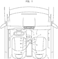
- an operational portion structure 1 of an operational operation portion in a vehicle according to the present embodiment is arranged at a side direction (right side direction) of a driver seat 3 positioning behind a steering wheel 2.
- a passenger seat 4 is arranged at the right side of the driver seat 3.
- a car according to the present embodiment is a car of left handle in which the steering wheel 2 is provided at the left side and the operational portion structure 1 is provided at the lateral side of the passenger seat 4 for the driver seat 3 (right side in Fig. 1 , abbreviated as "passenger seat side” hereinafter).
- an instrument panel 5 In the vehicle room, in front of the driver seat 3 and the passenger seat 4, it is provided an instrument panel 5 extending in a vehicle width direction (right and left direction, right and left direction in Fig. 1 ).
- a center console 6 is extended in a rear direction so as to continue to the instrument panel 5 from a center portion in the vehicle width direction of the instrument panel 5.
- the center console 6 is provided so as to extend in a front and back direction of the vehicle (up and down direction in Fig. 1 ) between the driver seat 3 and the passenger seat 4.
- the operational portion structure 1 is provided on the center console 6.
- a display 7 is arranged to the center portion in the vehicle width direction of the instrument panel 5.
- the display 7 is, for example, a liquid-crystal clor display device and displays information or images concerning in-vehicle equipments such as audio device or navigation device and the like for the occupant of the car.
- the audio device is a device to play back music or video and includes a CD/DVD palyer or a AM/FM tuner and the like.
- the navigation device is a device to provide road map information and to conduct route guide to destination. Furhter, in the vehicle room, it is provided another in-vehicle equipments such as speakers to reproduce playback sounds of the audio device and guide sounds of the navigation device and the like.
- the operational portion structure 1 is provided on an upper surface portion of the center console 6 extending in the front and back direction of vehicle.
- the operational portion structure 1 roughly possesses a an operational portion arrangement portion 11 having a base surface 10 like a horizontal plane beoming a standard surface on which various operational portions and the kike are arranged and a raised portion 12 which is formed at a rear side of the operational portion arrangement portion 11 and is raided against the base surface 10.
- the rear portion of the operational portion arrangement portion 11 and the front portion of the raised portion 12 are mutually overlapped.
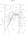
- the operational portion structure 1 possesses a touch pad 14 as a touch operational portion, a rest surface formation portion 15 formed behind the touch pad 14, an audio switch 16 as an audio operational portion integrally formed with a front portion of the rest surface formation portion 15 at a rear position of touch pad 14. Further, in the operational portion arrangement portion 11, cup holders 17 and a shift lever 18 are arranged.
- the cup holders 17 are formed at a front portion of the operation portion arrangement portion 11. Two of the cup holders 17 are arranged side by side.
- the cup holders 17 are recess protions opened in substantially circular shape against the base surface 10.
- the sfift lever 18 is an operational portion to operate a transmission provided in a car.
- the shift lever 18 is arranged at a portion of the driver seat side in an intermediate position in the front and back direction on the operational portion arrangement portion 11. Namely, the shift lever 18 is arranged behind the cup holder 17a of the driver seat side.
- the shift lever 18 is protruded upward from the base surface 10 with a substantially vertical state against the base surface 10.
- the shift lever 18 is provided so that the shift lever 18 can be moved and operated in predetermined directions including the front and back direction and positions of the shift driver 18 can be exchanged step by step.
- Th touch pad 14 is utilized, for example, for operation on the screen display such as movement of cursor and the like on the operation screen displayed on the display 7 provided in the instrument panel 5 in the vehicle room.
- the touch pad 14 has a contacted operational surface 14a receiving contact as operation input.
- the touch pad 14 has a rectangular outline shape in a planer view and a pair of sides (right and left sides) mutually opposing in such outline shape are provided so that both sides are arranged substantially along the front and back direction.
- the contacted operational surface 14a is formed in a plan surface having a rectangular outline shape.
- the touch pad 14 is wholly formed so as to be substantially flush with the base surface 10.
- the touch pad 14 is arranged at a portion of the passenger seat side in an intermediate position in the front and back direction on the operational portion arrangement portion 11. Namely, the touch pad 14 is arranged behind the cup holder 17b of the passenger seat side. Further, at the next to the right of the shift lever 18, the touch pad 14 is arranged in substantial half portion of the passenger seat side in the vehicle width direction at the intermediate portion in the front and back direction of th base surface 10.
- electrostatic electrode paths are formed over entire lower surface area of the contacted operational surface 14a and these electrostatic electrode paths are connected to an electrostatic capacitance control unit. According to this constitution, electrostatic capacitance is detected, thereby it is detected which contact portion on the contacted operational surface 14a is contacted.
- the rest surface formation portion 15 is a porption constituting the raised portion 12 formed behind the operational portion arrangement portion 11 in the operational portion structure 1. Further, the rest surface formation portion 15 is a portion in which the palm rest for the touch pad 14 and the arm rest for the driver seat 3 and the passenger seat 4 are integrally constituted.
- the rest surface formation portion 15 is formed behind the touch pad 14 and includes a palm rest portion 21 for operating the touch pad 14 and an arm rest portion 22 forming a rest surface 15a continuous to the palm rest portion 21.
- the rest surface 15a is an upper surface of the rest surface formation portion 15 and is formed in a horizontal plane or substantially horizontal plane forming a slightly convex surface.
- the rest surface formation portion 15 is a coated surface portion with cushion property so as to coat the upper surface of the center console 6.
- the rest surface formation portion 15 extends the palm rest portion 21 to the position near the rear side of the touch pad 14, and at the rear side, the rest surface formation portion 15 extends the arm rest portion 22 to the position near the rear end portion of the center console 6.
- the palm rest portion 21 and the arm rest portion 22 are portions to form the rest surface 15a and have a shape intefrally and continuously formed without classification in shape therebetween.
- the palm rest portion 21 constitutes a palm rest surface
- the arm rest portion 22 constitutes an arm rest surface.
- the rest surface formation portion 15 has a constitution in which the palm rest is integrally formed at the front end portion of the portion mainly functioning as the arm rest.
- the rest surface formation portion 15 has a constant width portion 15c at a rear portion thereof, the constant width portion 15c having a substantially constant width and a shape along a rectangular shape the front and back direction of which corresponds to the longitudinal direction in a plan view.
- the rest surface formation portion 15 has a tapered shape portion 15d forming a shape along a substantially triagle shape having a vertex at the front side as a schematical shape in a plan view.
- the tapered shape portion 15d and the constant width portion 15c are formed by a proportion of 2:3 according to a dimension in the front and back direction.
- the tapered shape portion 15d has a side portion 15e at the passenger seat side substantially along the front and back direction and a hypotenuse side portion 15f slanted against the front and back direction and a front side portion 15g substantially along the right and left direction.
- the side portion 15e at the passenger seat side is a side portion at the anti-driver seat side (passenger seat side) which is substantially parallel with the front and back direction of the vehicle.
- the hypotenuse side portion 15f at the driver seat side is a side portion at the driver seat side slanted toward the passenger seat side from the driver seat side along the rear side to the front side of the vehicle against the front and back direction of the vehicle.
- the tapered shape portion 15d has a shape along substantially trepazoid shape in which the front side becomes the upper bottom side in a plan view by the sid eportion 15e at the passenger seat side, the hypotenuse side portion 15f at the driver seat side and the front side portion 15g.
- the hypotenuse side portion 15f of the tapered shape portion 15d goes along a straight line S1 making an acute angle ⁇ against the front and back direction in a plan view (see Fig. 3 ).
- the angle ⁇ for example, lies in a range of about 20 ⁇ 40°. In the example shown in Fig., the angle ⁇ is about 30°.
- the rest surface formation portion 15 has the tapered shape formed by the side portions of the side portion 15e at the passenger seat side and the hypotenuse side portion 15f at the driver seat side, as the front shape in a plan view. Further, in the rest surface formation portion 15, the tapered shape portion 15d having a tapered shape in a plan view mainly functions as the palm rest portion 21 and the constant width portion 15c behind the tapered shape portion 15d mainly functions as the arm rest portion 22.
- the rest surface formation portion 15 with the form mentioned in the above in a plan view is provided in a state that substantial whole of the tapered shape portion 15d is overlapped with the rear portion of the operational portion arrangement portion 11. Namely, in a plan view, the rest surface formation portion 15 is provided in a state that substantial whole of the tapered shape portion 15d is digged into the rear side of the operational portion arrangement portion 11 from the rear side thereof.
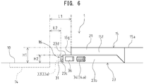
- a portion of the rest surface formation portion 15 overlapping with the operational portion arrangement portion 11 is parallel formed with a distance therebetween over the base surface 10. Namely, as shown in Fig. 4 , the tapered shape portion 15d of the rest surface formation portion 15 extends forward so as to separate upward with a predetermined distance D1 against the base surface 10.
- the room portion 10a of the base surface 10 at the driver seat side of the tapered shape portion 15d.
- the room portion 10a is a portion exposed without being covered with the rest surface formation portion 15 based on the tapered shape of the tapered shape portion 15d occurring by the hypotenuse side portion 15f at the driver seat side on the base surface 10.
- the room portion 10a for example, there are formed output-input terminals and the like connected to outer connected equipments for the in-vehicle equipments.
- the audio switch 16 is an operational portion to operate the audio device loaded in the vehicle.
- the audio switch 16 is formed between the touch pad 14 and the arm rest portion 22 of the rest surface formation portion 15 in the front and back direction.
- the audio switch 16 has a casing 23 with an outline shape of plank having a shape in a plan view (plate plane shape) along a substantially triangle shape, similar to the tapered shape portion 15d.
- the audio switch 16 is provided so as to be sandwiched between the base surface 10 and the palm rest portion 21 of the rest surface formation portion 15 (tapered shape portion 15d) with the predetermined distance D1 therebetween as mentioned above while making the plate plane of the casing 23 as the horizontal direction. Namely, the audio switch 16 is interposed between the base surface 10 and the palm rest portion 21 of the rest surface formation portion 15 and is provided on the base surface 10 so as to constitute a lower layer portion against the palm rest portion 21 constituting a surface layer portion.
- the audio switch 16 is provided so that the casing 23 thereof is fixed on the base surface 10. Further, the audio switch 16 is provided so that the palm rest portion 21 of the rest surface formation portion 15 is put and fixed on the casing 23. The audio switch 16 is provided so that a large part of the casing 23 is overlapped with the palm rest portion 21 of the rest surface formation portion 15. As mentioned, the audio switch 16 is provided so as to integrally form a layered structure in cooperation with the palm rest portion 21.
- the audio switch 16 is provided so that the shape in a plan view with a substantially triangle shape of the casing 23 corresponds to a shape in a plan view with a substantially triangle shape of the tapered shape portion 15d of the rest surface formation portion 15. Further, the audio switch 16 is provided so that the front end portion of the casing 23 is protruded forward than the front end portion of the tapered shape portion 15d. that is , the front end portion of the palm rest portion 21. Therefore, on the base surface 10, it is constituted a stepwids portion with 2 steps based on the the front end portion of the audio switch 16 and the front end portion of the palm rest portion 21.
- the casing 23 of the audio switch 16 has a side surface 23a at the passenger seat side substantially along the front and back direction, a side surface 23b at the driver seat side slanted against the front and back direction and a side surface 23c of the front side substantially along the right and left direction, as the side surfaces constituting the shape in a plan view.
- a rear portion of side surface 23a at the passenger seat side is overlapped with the side portion 15e at the passenger seat side and a rear portion of the side surface 23b at the driver seat side is overlapped with the hypotenuse side portion 15f at the driver seat side.
- the front side surface 23c positions more forward than the front side portion 15g.
- the front side surface 23c positions between the touch pad 14 and the palm rest portion 21 in the front and back direction of the vehicle.
- the casing 23 has a shape substantially along a trapezoid shape in which the front side becomes the upper bottom side in a plan view, based on the side surface 23a at the passenger seat side, the side surface 23b at the driver seat side and the front side surface 23c, similarly to the tapered shape portion 15d.
- the audio switch 16 has various switch operational portions on the side surface of the casing 23.
- the audio switch 16 has a front operational portion provided on the front side surface 23c and a side operational portion provided on the side surface 23b at the driver seat side positioning at the driver seat side against the palm rest portion 21.
- the audio switch 16 has three operational portions consecutively provided in the lateral direction as the front operational portion arranged on the front side surface 23c. These three operational portions are, as shown in Fig. 5 , push buttons 31 and 32 provided at the right and left both sides at the front end portion of the audio switch 16 and a wheel botton 33 arranged between the right and left push buttons 31,32. Further, the audio switch 16 has a thumb wheel 34 as the side oeprational portion provided on the side surface 23b at the driver seat side. Further, at the front end portion of the side surface 23a at the passenger seat side, a push button 35 is provided and a push button 36 is arranged at the front end portion of the side surface 23b at the driver seat side.
- the push buttons 31, 32 are push operational portions each of which receives press operation.
- the push button 31 is provided at the driver seat side of the wheel button 33 and the push button 32 is provided at the passenger seat side of the wheel button 33.
- the wheel button 33 is arranged at the center in the longitudinal direction (substantially right and left direction) of the front side surface 23c.
- the wheel button 33 is a cylindrical rotational operation portion in which a rotational axis direction corresponds to a direction along the front side surface 23c in a plan view.
- the wheel button 33 has a cylindrical operational portion body 33a which is rotatably supported in the casing 23 so that a central axis becomes a rotational axis direction.
- the operational portion body 33a is supported in a state that an approximate half portion in a radial direction is protruded from the front side surface 23c, that is, in a state that the operational portion body 33a is protruded in an approximate semicylindrical state from the front side surface 23c.
- On an outer peripheral surface of the operational portion body 33a a plurality of grooves along the rotational axis direction of the operational portion body 33a are formed in a peripheral direction.
- the wheel button 33 corresponding to the operational portion positioned at the center is a different kind of operational portion in which outline shape and input operation are different against the push buttons 31, 32 corresponding to the right and left operational portions.
- the push buttons 31, 32 are the operational portions which receive press operation as input operation and the wheel button 33 is the operational portion which receives rotational operarion as input operation.
- the wheel button 33 may be an operational portion which receives press operation in addition to rotational operation as input operation. That is, it may be enough that the wheel button 33 is a different kind of operational portion which has a different shape or receives different input operation against the right and left push buttons 31, 32 .
- the thumb wheel 34 is provided at a position of more front side than an intermediate portion.
- the thumb wheel 34 is a cylindrical rotational operation portion a rotational axis direction of which is a direction along the side surface 23b at the driver seat side in a plan view.
- the thumb wheel 34 has a cylindrical operation portion body 34a rotatably supported to the casing 23 while a center axis is made as a rotational axis direction.
- the operational portion body 34a is supported in a state that a substantial half thereof in a radius direction is protruded from the side surface 23b at the driver seat side, that is, the operational portion body 34a is supported so as to protrude from the side surface 23b at the driver seat side in a substantial semicylindrical state.
- a plurality of grooves along the rotationa axis direction of the operational portion body 34a are formed in a peripheral direction.
- the thumb wheel 34 is an operation portion which receives rotational operation as input operation, similar to the wheel button 33.
- the thumb wheel 34 may be an operational portion which receives press operation in addition to rotational operation as input operation.
- the push button 35 arranged on the front end portion of the side surface 23a at the passenger seat side and the push button 36 arranged on the front end portion of the side surface 23b at the driver seat side are push operational portions which receive press operation, similar to the push buttons 31, 32.
- the push button 36 positions in front of the thumb wheel 34.
- each of various functions concerning the audio device is allotted.
- various functions concerning the audio device for example, volume adjustment function of playback sound, playback ⁇ stop function of playback sound, seek track function, tuner tunig function, exchange function of various media such as CD/DVD player or AM/FM tuner and the like.
- a recess portion 10b with a long hole shape along the longitudinal direction of the front side surface 23c is formed.
- the recess portion 10b is, for example, a portion to avoid that nails contact with the base surface 10 when the wheel button 33 or the push button 31, 32 are operated by fingers of a hand in a state that a palm is put on the palm rest portion 21. Therefore, a shape ⁇ dimension and depth of the recess portion 10b are designed so as to avoid that nails of fingers operating the wheel button 33 and the like contact with the base surface 10 even if nails of an operator are long to some extent, so that good operability of the wheel button 33 or the push buttons 31, 32 can be obtained.
- the audio switch 16 integrally formed with the palm rest behind the touch pad 14 arranged substantially flush with the base surface 10 and the palm rest portion 21 of the rest surface formation portion 15 is provided in a form of stacked stepwise fashion.
- the operational portion structure 1 has a constitution that the touch pad 14, the audio switch 16 and the rest surface formation portion 15 (palm rest portion 21) are serially arranged in the front and back direction from the front side in order.
- dimension of each portion will be set as follows.
- dimension to be focused on in the operational portion structure 1 as shown in Fig. 6 , it will exist dimension HI between the base surface 10 and the upper end position of the front side portion 15g in the rest surface formation portion 15 in the up and down direction (height direction).
- dimension H2 between the base surface 10 and the position of the upper surface 23d of the casign 23 in the audio switch 16.
- illustration of the shift lever 18 is omitted.
- the audio switch 16 which is desired to be arranged to the near position to the touch pad 14 as the operational portion of multi-media system, becomes distant from the touch pad 14.
- the dimension L2 is small, it will occur as cause inviting misoperation a situation that the finger to operate any one of the touch pad 14 and the audio switch 16 interferes with any other operational portion. Therefore, it will become difficult to obtain mutually independent good operability of the touch pad 14 and the audio switch 16.
- the thumb wheel 34 which the audio switch 16 possesses on the side surface 23b at the driver seat side is an operational portion to which customizing function in the operational direction is given.
- the thumb wheel 34 in the left handle drive car, the thumb wheel 34 is operated by the thumb 25b of the right hand 25 of the driver putting on the palm rest portion 21.
- rotational operation of the thumb wheel 34 provided in a state that the rotational axis direction becomes along the horizontal direction on the side surface 23b at the driver seat side of the casing 23, rotational operation to the upper side or rotational operation to the lower side is conducted.
- each rotational operation direction of the thumb wheel 34 of upward directiona and downward direction function corresponding to the rotational operation in each direction can be voluntarily set by a user.
- a rotational direction A1 to the upper side is utilized as "UP" rotational direction to raise various values such as function to raise volume of the audio device or function to raise frequency of the tuner.
- a rotational direction A2 to the lower side is utilized as "DOWN" rotational direction to lower various values such as function to lower volume of the audio device or function to lower frequency of the tuner.
- the thumb wheel 34 is constituted so that function corresponding to the rotational operation direction can be customized.
- corresponding relation between the rotational operation direction of the thumb wheel 34 and the function corresponding to each direction it is constituted that the corresponding relation shown in Fig. 7A or the opposite corresponding relation can be selected by the user.
- the rotational direction A1 to the upper side is utilized as the rotational direction of "DOWN" to lower various values such as volume of the audio device and the like and the rotationa direction A2 to the lower side is utilized as the rotational direction of "UP” to raise various values such as volume of the audio device and the like.
- Selection ⁇ exchange of the corresponding relation between the operational direction of the thumb wheel 34 and the corresponding function is done, for example, by setting on the display screen of the display 7 or operation of own thumb wheel 34 and the like such as long press operation of the thumb wheel 34.
- the relation between the rotational operation direction of the thumb wheel 34 and the function corresponding to each direction can be matched with the operational sense of the different user, for example, corresponding to difference of right handed or left handed of the user and right handle or left handle of the vehicle.
- this customizing function of the operational portion can be adopted for the wheel button 33 which is the operational portion of wheel type similar to the thumb wheel 34.
- the rest surface formation portion 15 has a flexible skin portion 41 forming the rest surface 15a and an inner layer portion 42 covered by the skin portion 41 and formed from material with cushion property.
- the skin portion 41 is a leather sheet portion formed by artificial material such as synthetic leather having base sheet of artificial leather or natural cloth or natural material such as natural leather.
- the skin porption 41 is provided so as to cover whole of surface portion in the rest surface formation portion 15 and constitutes surface layer portion of the rest surface formation portion 15.
- the rest surface 15a is fromed by surface of the skin portion 41.
- the inner layer portion 42 is a cushion layer formed from material with cushion property, for example, such as urethane foam made of foamed resin material such as polyurethane and the like, sponge, polyethylene fiber or latex.
- the inner layer portion 42 constitutes inner layer portion of the rest surface formation portion 15 based on that whole of surface portion is covered by the skin portion 41.
- the inner layer portion 42 deforms following deformation of the skin portion 41.
- the rest surface formation portion 15 having the skin portion 41 and the inner layer portion 42 it is provided as a part of the inner layer portion 42 a rigid portion 43 which is a portion to determine the position of the palm of the operator put on the palm rest portion 21.
- the rigid portion 43 is a portion which is relatively rigid against the other part of the inner layer portion 42.
- it is provided as the rigid portion 43 a front rigid portion 43A to mainly determine the position of the palm suitable for operation of the touch pad 14 and a rear rigid portion 43B to mainly determine the position of the palm suitable for operation of the audio switch 16.
- each rigid portion 43 is provided, for example, in a circle area or an ellipse area in a plan view or in a band form in the right and left direction so as to across the palm rest portion 21.
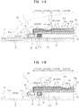
- the front rigid portion 43A is provided in the inner layer portion 42 at the front side of an area which is supposed that the palm of the operator is put on when the touch pad 14 is operated. That is, among the soft portions 44, the soft portion 44A behind the fornt rigid portion 43A becomes a portion where the palm of hand of operator is put on when the touch pad 14 is operated and becomes a convex portion which is compressed and deformed with deformation of the skin portion 41 by press of the rest surface 15a through hand or due to weight of hand (see Fig. 9A ).
- the rear rigid portion 43B is provided in the inner layer portion 42 at the front side of an area which is supposed that the palm of the operator is put on when the audio switch 16 is operated. That is, among the soft portions 44, the soft portion 44B behind the front rigid portion 43B becomes a portion where the palm of hand of operator is put on when the audio switch 16 is operated and becomes a convex portion which is compressed and deformed with deformation of the skin portion 41 by press of the rest surface 15a through hand or due to weight of hand (see Fig. 9B ).
- rigid urethane foam is adopted as the material of the rigid portion 43 and soft urethane foam or semi-rigid urethane foam is adopted as the material of the soft portion 44.
- semi-rigid urethane foam is intermediate material of soft urethane foam and the rigid urethane foam.
- rigid sponge is adopted as the material of the rigid portion 43 and soft sponge is adopted as the material of the soft portion 44.
- so-called high rebound cushion material centering on latex is adopted as the material of the rigid portion 43 and so-called low rebound cushion material centering on urethane foam is adopted as the material of the soft portion 44.
- two rigid portions 43 of the front rigid portion 43A for operating the touch pad 14 and the rear rigid portion 43B for operating the audio switch 16 are provided, it is not limited to this.
- the palm position is determined as the common operational position of the touch pad 14 and the audio switch 16
- one rigid portion 43 may be adopted.
- the audio switch 16 can be arranged near and behind the touch pad 14. Thereby, it can be conducted grouping of the touch pad 14 and the audio switch 16 on the arrangement surface of the center console 6, both the touch pad 14 and the audio switch 16 as operational portions of multi-media system often being mutually related and operated. Further, good operability for these operational portions can be obtained.
- the audio switch 16 is provided so that the audio switch 16 becomes a lower layer portion in a case that the palm rest portion 21 which is an integral part with the arm rest portion 22 in the rest surface formation portion 15 becomes an upper layer portion, that is, so that the audio switch 16 forms an integral layer structure with the palm rest portion 21.
- the audio switch 16 can be arranged near the touch pad 14 as much as possible. Therefore, each operational portion in the touch pad 14 and the audio switch 16 can be operated without moving the hand put on the palm rest portion 21 or with only slightly moving thereof and without behavior replacing the hand.
- the palm rest portion 21 can be commonly used as the palm rest of the touch pad 14 and the audio switch 16
- hand position of the operator is determined against each operational portion in the touch pad 14 and the audio switch 16 and blind operability of both operational portions can be improved.
- buden of driver of a car can be reduced and high safty can be secured.
- the audio switch 16 and the palm rest portion 21 arranged behind the touch pad 14 are provided under a state that a large part each other is overlapped in the up and down direction, space efficiency can be improved in arrangement space of the operational portions on the center console 6.
- the touch pad 14 and the audio switch 16 can be arranged while avoiding interference with the other portion such as cup holder 17 and the shift lever 18 provided on the center console 6 and efficiently utilizing space.
- each operational portion can be easily arranged at a position where the driver can operate each operational portion while retaining elbows at netural positions, as a result, operability can be improved.
- the touch pad 14 and the audio switch 16 are arranged in the front and back direction at the passenger seat side on the center console 6 including the palm rest portion 21 and also are constituted approximately symmetrical. According to this constitution, since good accessibility against each operational portion can be obtained for an occupant of the passenger seat 4, good operability for each of an occupant of the driver seat 3 and the an occupant of the passenger seat 4 can be obtained with good balance.
- the audio switch 16 has the right and left push buttons 31, 32 and the wheel button 33 as the front operational portions provided on the front side surface 23c of the casing 23 positioned between the touch pad 14 and the palm rest portion 21 in the front and back direction, the thumb wheel 34 and the push button 36 as the side operational portions provided on the side surface 23b at the driver seat side and also the push button 35 as the operational portion provided on the side surface 23a at the passenger seat side.
- various operational portions respectively possessed by the touch pad 14 and the audio switch 16 can be efficiently operated while utilizing movement of fingers of hand in the posture that the palm is put on the palm rest portion 21.
- the contacted surface operational surface 14a of the touch pad 14 is operated by an index finger 25b of a right hand 25 put on the palm rest portion 21 and the thumb wheel 34 is operated by a thumb 25a, the right and left push buttons 31, 32 are operated by the index finger 25b and a middle finger 25c. Furthermore, the push button 35 is operated by the middle finger 25c and the push button 36 is operated by the thumb 25a.
- good blind operability can be obtained for various functions of the operational portions of multi-media system.
- the rest surface formation portion 15 has the tapered shape formed by side portions including the side portion 15e at the passenger seat side and the hypotenuse side portion 15f at the driver seat side as the front shape in a plan view. According to this constitution, it can be avoided that the rest surface formation portion 15, which is the raised portion for the base surface 10 on the center console 6, is protruded toward the portion at the driver seat side. A flat space as the base surface 10 can be secured in the driver seat side of the rear upper surface of the center console 6. Thereby, it can be avoided that behavior of arm such as contact of elbow of the right hand with the rest surface formation portion 15 interferes with the rest surface formation portion 15 when the driver sitting on the driver seat 3 operates the operational portion on the center console 6 or operates the steering handle 2. As a result, operability of each operational portion including blind operability can be efficiently improved.
- the side surface 23b at the driver seat side of the audio switch 16 can be let along the hypotenuse side portion 15f at the driver seat side and the thumb wheel 34 can be arranged on the side surface 23b at the driver seat side.
- the rest surface formation portion 15 has the skin portion 41 formed from leather sheet and the like and the inner layer portion 42 formed from cuchion material covered by the skin portion 41 and the rigid portion 43 which is a relatively rigid portion is provided on a portion constituting the palm rest portion 21 in the inner layer portion 42.
- the front rigid portion 43A is utilized as a portion to position the palm.
- the palm of the right hand 25 of the operator put on the palm rest portion 21 positions at the rear side of the front rigid portion 43A
- a portion of the soft portion 44A at the rear side of the front rigid portion 43A is dented with deformation of the skin portion 41, based on press of the rest surface 15a through hand weight or hand (see dent 44x).
- the rear rigid portion 43B is utilized as a portion to position the palm.
- the palm of the right hand 25 of the operator put on the palm rest portion 21 positions at the rear side of the rear rigid portion 43B
- a portion of the soft portion 44B at the rear side of the rear rigid portion 43B is dented with deformation of the skin portion 41, based on press of the rest surface 15a through hand weight or hand (see dent 44y).
- position of the palm can be positioned to a position near side of the rigid portions (43A, 43B) by hand feeling. That is, based on foreign body feeling of the rigid portion 43 which is relatively rigid against the soft portion 44, position of the palm is respectively determined at the position near side of each rigid portion 43. Thereby, without directly watching hands, since positioning of the palm can be conducted on the rest surface formation portion 15, good blind operability can be obtained.
- the rigid portion 43 is formed in the inner layer portion 42 of the rest surface formation portion 15, a portion to position the palm in the palm rest portion 21 can be provided without affecting appearance of the rest surface formation portion 15. Thereby, blind operability can be improved while securing designability of the rest surface formation portion 15.
- the wheel button 33 positioned at the center is different in an outline shape and input operation against the right and left push buttons 31, 32, thus the wheel button 33 is a different kind of operational portion.
- three operational portions can be distinguished by hand feeling of the operator without directly watching the operation portions and center postion of three operational portions can be grasped. Thereby, blind operability can be improved.
- the wheel button 33 is a different kind of operational portion against the right and left push buttons 31, 32, it may be enough that the wheel button 33 is different kind of operational portion against at least one of the right and left operational portions.
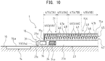
- Modification 1 of the operational portion structure 1 according to the present embodiment will be described with reference to Figs. 10 to 12 .
- the modification 1 is a modification for the structure of the rest surface formation portion 15.
- a rest surface formation portion 15X in the modification 1 has the skin portion 41 and the inner layer portion 42, similar to the rest surface formation portion 15 mentioned in the above. Further, in the rest surface formation portion 15X of the modification 1, the inner layer portion 42 has an uneven shape portion 45 in a portion constituting at least the palm rest portion 21.
- the uneven shape portion 45 is formed at a side of the skin portion 41 of the inner layer portion 42, that is, at an upper side. Therefore, in the inner layer portion 42, a side of the uneven shape portion 45 becomes a contact side for a back surface 41a of the skin layer 41.
- the uneven shape portion 45 is formed from many protrusion 46 with mountain shape provided so as to protrude upward.
- the protrusions 46 are continuously arranged in both the front and back direction and the right and left direction. That is, the uneven shape portion 45 is provided so that unevenness is formed over a whole of the surface side of the inner layer portion 42 in the palm rest portion 21.
- the uneven shape portion 45 may be formed over a whole of the inner layer portion 42 (also the arm rest portion 22).
- the uneven shape portion 45 formed on the inner layer portion 42 includs an uneven portion 47 for guide which is a portion with height of uneveness different from the other portion, as a portion to determine a position of the palm of the operator put on the palm rest portion 21.
- the uneven portion 47 for guide is formed from protrusions 46A each height of which is higher than the protrusion 46 in the other protion.
- a front uneven portion 47A for guide to determine a palm position suitable for mainly operation of the touch pad 14 and a rear uneven portion 47B for guide to determine a palm position suitable for mainly operation of the audio switch 16 are provided.
- the protrusion 46 in a portion other than the uneven portion 47 for guide of the uneven shape portion 45 has a height to secure a distance to back surface 41a of the skin portion 41 in the rest surface formation portion 15X in a natural state.
- the protrusion 46A constituting the uneven portion 47 for guide has a height to contact with the back surface 41a of the skin portion 41 in the rest surface formation portion 15X in a natural state.
- each uneven portion 47 for guide is, for example, formed in a circle area or an ellipse area in a plan view or formed as a band form in the right and left direction so as to across the palm rest portion 21.
- the height of each protrusion 46 in the normal uneven portion 49 is, for example, set to a height to separate by a predetermined dimensional distance against the back surface 41a of the skin portion 41 while vertex of each protrusion 46 becomes along a plane shape of the skin portion 41.
- a plurality of protrusions of the normal uneven portion 49 are provided so that each vertex becomes along a virtual surface 41b parallel with the back surface 41a of th skin portion 41.
- a space 48 layered along the plane shape of the skin portion 41 is formed between the normal uneven portion 49 and the skin portion 41.
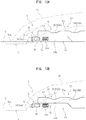
- the front uneven portion 47A for guide is formed at the front side of a portion supposed that the palm of the hand of the operator is put on when the touch pad 14 is operated. That is, among the normal uneven portions 49, the normal uneven portion 49A behind the front uneven portion 47A for guide becomes a portion where,for example, the palm of the right hand 25 of the operator is put on when the touch pad 14 is operated and becomes a dented portion which is compressed and deformed while accompanying deformation of the skin portion 41 by press of the rest surface 15a through hand weight or hand press (see Fig. 11A ).
- the rear uneven portion 47B for guide is provided in front of a portion supposed that the palm of the hand of the operator is put on when the audio switch 16 is operated. That is, mong the normal uneven portions 49, the normal uneven portion 49B behind the rear uneven portion 47B for guide becomes a portion where,for example, the palm of the right hand 25 of the operator is put on when the audio switch 16 is operated and becomes a dented portion which is compressed and deformed while accompanying deformation of the skin portion 41 by press of the rest surface 15a through hand weight or hand press (see Fig. 11B ).
- the uneven portion 47 for guide of the front uneven portion 47A for guide to operate the touch pad 14 and the rear uneven portion 47B for guide to operate the audio switch 16 it is not limited to this.
- the uneven portion 47 for guide is provided at one position.
- the consatitution of the modification 1 based on that feeling difference due to deformability difference of the rest surface formation portion 15X, the putting position of the hand of the operator on the palm rest portion 21 can be guided.
- the front uneven portion 47A for guide is utilized as the portion to position the palm when the touch pad 14 is operated.
- the normal uneven portion 49A behind the front uneven portion 47A for guide is dented while accompanying deformation of the skin portion 41 by press of the rest surface 15a through hand weight or hand press (dent 49x).
- the rear uneven portion 47B for guide is utilized as the portion to position the palm when the audio switch 16 is operated.
- the normal uneven portion 49B behind the rear uneven portion 47B for guide is dented while accompanying deformation of the skin portion 41 by press of the rest surface 15a through hand weight or hand press (dent 49y).
- the palm can be positioned to the near side of the uneven portion 47 (47A, 47B) for guide by hand feeling. That is, based on foreign body feeling of the uneven portion 47 for guide which is not relatively deformable against the normal uneven portion 49, the palm postion is repspectively determined at the near side position of each uneven portion 47 for guide. Thereby, since the palm can be positioned on the rest surface formation portion 15X without directly watching the hand, good blind operability can be obtained.
- the portion to position the palm on the palm rest portion 21 can be provided without affecting the appearance of the rest surface formation portion 15X. Thereby, blind operability can be improved while securing designability of the rest surface formation portion 15X.
- the uneven portion 47 for guide of the uneven shape portion 45 is the portion that height of unevenness is made different against the other portions, as the uneven portion 47 for guide, it may be conceivable that at least one of unevenness height and unevenness pitch is different against the other portions.
- the uneven portion 47 of the uneven shape portion 45 for example, as shown in Fig. 12A , it may be conceivable that the unevenness pitch is different against the other portions.
- each protrusion 46 of the normal uneven portion 49 has a height so as to contact with the back surface 41a of the skin portion 41 in the rest surface formation portion 15X in a natural state.
- the uneven portion 47 for guide of the uneven shape portion 45 for example, as shown in Fig. 12B , it may be conceivable that the uneven portion is a portion where both unevenness height and unevenness pitch are different against the other portions.
- an arrangement pitch in at least any direction of the front and back direction and the right and left direction is provided so as to become smaller against the arrangement pitch of the protrusions 46 in the normal uneven portion 49 of the uneven shape portion 45.
- each of a plurality of protrusions 46C constituting the uneven portion 47 for guide has a height to contact with the back surface 41a of the skin portion 41 in the rest surface formation portion 15X in a natural state and each of the protrusions 46 of the normal uneven portion 49 has a height to separate with a distance against the back surface 41a of the skin portion 41 in the rest surface formation portion 15X in a natural state.
- the plural protrusions 46 of the normal uneven portion 49 are provided so as to make along the virtual surface 41b pallarel with the back surface 41a of the skin portin 41 and above the normal uneven portion 49, it is provided the space 48 in layered along the plane shape of the skin portion 41.
- the uneven portion 47 for guide becomes the portion which is hard to deform and can guide the position where the hand of the operator is put on the palm rest portion 21.
- the rigid material relatively rigid against the normal uneven portion 49 is utilized such as the rigid portion 43 shown in Fig. 11 . That is, as difference of the portion hard to deform to determine the palm position of the hand of the operator in the palm rest portion 21 against the other portions, difference of material hardness may be utilized in addition to difference in shape of the uneven shape portion 45 having the uneven portion 47 for guide.
- a modification 2 of the operational portion structure 1 according to the present embodiment will be described with reference to Fig. 13 .
- the modification 2 is a modification concering the structure of the rest surface formation portion 15.
- the rest surface formation portion 15Y of the modification 2 has a recess 50 formed on the upper surface of the palm rest portion 21 as the portion to determine the position of the palm of the operator put on the palm rest portion 21.
- the recess 50 there are provided a front recess 50A to determine the palm position suitable for mainly operation of the touch pad 14 and a rear recess 50B to determine the palm position suitable for mainly operation of the audio switch 16.
- the recess 50 is formed in a shape integral with the skin portion 41 and the inner layer portion 42 in the rest surface formation portion 15Y in a natural state. That is, the recess along the recess 50 in the surface side of thr inner layer portion 42 is formed and the recess is formed also in the skin portion 41 so as to follow the shape of the above recess.
- the recess 50 is, for example, formed in a circle or ellipse area in a plan view in a collapsed state or in a groove form in the right and left direction so as to across the palm rest portion 21.
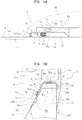
- the front recess 50A is formed at a portion supposed that the hand palm of the operator is put on when the touch pad 14 is operated on the rest surface 15a of the palm rest portion 21. That is, as shown in Fig. 13A , the front recess 50A provided in front of the palm rest portion 21 becomes a portion , for example, where the palm of the right hand of the operator is put on when the touch pad 14 is operated, thus the front recess 50A is utilized for the portion to position the palm of the operator in operation of the touch pad 14.
- the rear recess 50B is formed at a portion supposed that the hand palm of the operator is put on when the audio switch 16 is operated on the rest surface 15a of the palm rest portion 21. That is, as shown in Fig. 13B , the rear recess 50B provided in the rear side of the palm rest portion 21 becomes a portion , for example, where the palm of the right hand of the operator is put on when the audio switch 16 is operated, thus the rear recess 50B is utilized for the portion to position the palm of the operator in operation of the audio switch 16.
- the modification 2 based on the shape of the surface protion of the rest surface formation portion 15Y, it can be guided the position where the hand of the operqtor is put on in the palm rest portion 21. Thereby, since the palm can be positioned on the rest surface formation portion 15Y, good blind operability can be obtained.
- the front recess 50A for operation of the touch pad 14 and the rear recess 50B for operation of the audio switch 16 are formed in the palm rest portion 21, it is not limited to this.
- the recess 50 is provided at one position.
- the recess 50 is formed as the shape of the skin portion 41 and the inner layer portion 42, for example, it may be conceivable that the recess 50 is formed by embedding a plastic guide member in the skin portion 41.
- the modification 3 of the operational portion structure 1 according to the present embodiment will be described with reference to Fig. 14 .
- the modification 3 is a modification for the structure of the rest surface formation portion 15 and concerns operation of the audio switch 16.
- the recess for thumb 60 is formed in a shape integral with the skin portion 41 and the inner layer portion 42 in the rest surface formation portion 15Z in a natural state. That is, a recess along the recess for thumb 60 is formed at a position of driver seat side of the inner layer portion 42 and a recess is formed also in the skin portion 41 so as to follow the recess shape described in the above.
- the recess for thumb 60 is, for example, formed in a circle or ellipse area in a collapsed state.
- the recess for thumb 60 is formed at a portion supposed that thumb's belly of the thumb 25a of the hand of the operator fits when the thumb wheel 34 of the audio switch 16 is operated, that is, thumb is to be put.
- the recess for thumb 60 formed at the side portion of the driver seat side of the palm rest portion 21 becomes a portion where the thumb 25a of the right hand 25 of the operator on the palm rest portion 21 fits and is utilized as a portion to position the thumb 25a for operation of the thumb wheel 34.
- the recess for thumb 60 is formed corresponding to posture of the thumb 25a of the right hand under a state that the palm is put on the palm rest portion 21.
- the thumb wheel 34 is an operational portion to be mainly operated by the thumb's belly, thus the recess for thumb 60 is provided at a near position slanted rear upper against the thumb wheel 34. That is, the thumb wheel 34 is operated by finger portion of the thumb 25a positioning at finger tip side than finger portion positioning in the recess for thumb 60 in a state that the thumb 25a is positioned in the recess for thumb 60.
- the thumb wheel 34 is considered to be relatively hard to grasp in blind operation since the thumb wheel 34 is provided at a position separate rearward against the operational portions such as the wheel button 33 concentratively arranged to the front end portion of the audio switch 16.
- the finger position to operate the thumb wheel 34 can be positioned without directly watching hand, therefore it can be easily grapsed the position of the thumb wheel 34 existing at a position distant rearward against the operational portion positioned at the front end portion of the audio switch 16, as a result, good blind operability can be obtained.
- the operational portion structure 1 according to the present invention is adopted for the left handle car in which the steering handle 2 is provided at the left side
- the operational porption structure 1 can be similarly adopted for the right handle car which has a left-right opposite constitution against the case of the left handle car.
Landscapes
- Engineering & Computer Science (AREA)
- Theoretical Computer Science (AREA)
- General Engineering & Computer Science (AREA)
- Mechanical Engineering (AREA)
- Transportation (AREA)
- Chemical & Material Sciences (AREA)
- Combustion & Propulsion (AREA)
- Physics & Mathematics (AREA)
- General Physics & Mathematics (AREA)
- Human Computer Interaction (AREA)
- Aviation & Aerospace Engineering (AREA)
- Fittings On The Vehicle Exterior For Carrying Loads, And Devices For Holding Or Mounting Articles (AREA)
- Vehicle Step Arrangements And Article Storage (AREA)
- Switch Cases, Indication, And Locking (AREA)
Claims (6)
- Struktur (1) für einen Bedienabschnitt in einem Fahrzeug, der an einer Seite eines Fahrersitzes in einem Fahrzeug vorgesehen ist, mit:einem Antastbedienabschnitt (14), der eine zu berührende Bedienfläche (14a) auf einer Basisfläche (10) hat, die eine Berührung als einen Eingabevorgang aufnimmt;einem Auflageflächenbildungsabschnitt (15), der einen Handflächenauflageabschnitt (21) beinhaltet, der hinter dem Antastbedienabschnitt (14) vorgesehen ist und der zum Bedienen des Antastbedienabschnitts (14) eingesetzt wird, und einen Armauflageabschnitt (22) beinhaltet, der eine Auflagefläche (15a) zusammenhängend mit dem Handflächenauflageabschnitt (21) formt; undeinem Audiobedienabschnitt (16), der zwischen dem Antastbedienabschnitt (14) und dem Armauflageabschnitt (22) in einer Vorne- und Hinten-Richtung des Fahrzeugs vorgesehen ist, wobei der Audiobedienabschnitt (16) ein Audiogerät bedient, das in dem Fahrzeug eingerichtet ist;dadurch gekennzeichnet, dassder Audiobedienabschnitt (16) auf einer Vorderseitenfläche (23c) eines Gehäuses (23) vorgesehen ist, um eine zweistufige integrale Schichtstruktur mit zwei Stufen zu bilden, basierend auf einem vorderen Endabschnitt des Audiobedienabschnittes (16) und einem vorderen Endabschnitt des Handflächenauflageabschnittes (21),der Audiobedienabschnitt (16) sowohl den vorderen Bedienabschnitt aufweist, der an der Vorderseitenfläche (23c) vorgesehen ist, die eine von Seitenflächen ist, die einen Grundriss des Gehäuses (23) des Audiobedienabschnittes (16) formt, der zwischen dem Antastbedienabschnitt (14) und dem Handflächenauflageabschnitt (21) in der Vorne- und Hinten-Richtung des Fahrzeugs positioniert ist, als auch einen Seitenbedienabschnitt (34, 36) aufweist, der an einer Seitenfläche (23b) des Fahrersitzes vorgesehen ist, die eine der Seitenflächen ist und die auf einer Fahrersitzseite an dem Handflächenauflageabschnitt (21) positioniert ist.
- Struktur (1) nach Anspruch 1,wobei der Auflageflächenbildungsabschnitt (15) einen Außenhautabschnitt (41) mit Flexibilität besitzt, der die Auflagefläche (15a) formt, und einen Innenschichtabschnitt (42) besitzt, der aus einem Material mit Dämpfungseigenschaft hergestellt ist und der mittels dem Außenhautabschnitt (41) abgedeckt ist; undwobei ein starrer Abschnitt (43) an einem Abschnitt vorgesehen ist, der den Handflächenauflageabschnitt (21) innerhalb des Innenschichtabschnittes (42) festlegt, um eine Handfläche eines Anwenders, die auf den Handflächenauflageabschnitt (21) gelegt ist, zu positionieren, wobei der starre Abschnitt (43) relativ starr gegenüber anderen Abschnitten in dem Innenschichtabschnitt (42) ist.
- Struktur (1) nach Anspruch 1,wobei der Auflageflächenbildungsabschnitt (15) einen Außenhautabschnitt (41) mit Flexibilität besitzt, der die Auflagefläche (15a) formt, und einen Innenschichtabschnitt (42) besitzt, der aus einem Material mit Dämpfungseigenschaft hergestellt ist und der mittels dem Außenhautabschnitt (41) abgedeckt ist,wobei der Innenschichtabschnitt (42) einen unebenen Formabschnitt (45) in einem Abschnitt besitzt, der zumindest den Handflächenauflageabschnitt (21) festlegt, undwobei der unebene Formabschnitt (45) einen Abschnitt beinhaltet, in dem zumindest entweder eine Ebenheitshöhe oder ein Ebenheitsabstand unterschiedlich ist gegenüber anderen Abschnitten, als ein Abschnitt, um eine Position der Handfläche des Anwenders zu bestimmen, die auf den Handflächenauflageabschnitt (21) gelegt ist.
- Struktur (1) nach Anspruch 1,
wobei eine Vertiefung (50) an einer oberen Fläche des Handflächenauflageabschnitts (21) des Auflageflächenbildungsabschnitts (15) gebildet ist, um eine Position der Handfläche des Anwenders zu bestimmen, die auf den Handflächenauflageabschnitt (21) gelegt ist. - Struktur (1) nach Anspruch 1,
wobei eine Vertiefung (50) für einen Daumen an einem seitlichen Flächenabschnitt auf der Fahrersitzseite des Handflächenauflageabschnitts (21) vorgesehen ist, um eine Daumenposition des Anwenders zu bestimmen, der den Seitenbedienabschnitt bedient. - Struktur (1) nach Anspruch 1,wobei drei Bedienabschnitte (31, 32, 33) zusammenhängend in einer horizontalen Richtung als der vordere Bedienabschnitt gestaltet sind, undwobei der Bedienabschnitt (32), der in einer Mitte zwischen drei Bedienabschnitten (31, 32, 33) positioniert ist, eine unterschiedliche Art von Bedienabschnitt ist, gegenüber entweder den rechten oder den linken Bedienabschnitten (31, 33).
Applications Claiming Priority (2)
| Application Number | Priority Date | Filing Date | Title |
|---|---|---|---|
| JP2016246676A JP6437992B2 (ja) | 2016-12-20 | 2016-12-20 | 車両用操作部構造 |
| EP17196745.8A EP3339078B1 (de) | 2016-12-20 | 2017-10-17 | Struktur für operativen abschnitt eines fahrzeugs |
Related Parent Applications (2)
| Application Number | Title | Priority Date | Filing Date |
|---|---|---|---|
| EP17196745.8A Division EP3339078B1 (de) | 2016-12-20 | 2017-10-17 | Struktur für operativen abschnitt eines fahrzeugs |
| EP17196745.8A Division-Into EP3339078B1 (de) | 2016-12-20 | 2017-10-17 | Struktur für operativen abschnitt eines fahrzeugs |
Publications (2)
| Publication Number | Publication Date |
|---|---|
| EP3715166A1 EP3715166A1 (de) | 2020-09-30 |
| EP3715166B1 true EP3715166B1 (de) | 2021-09-22 |
Family
ID=60119927
Family Applications (2)
| Application Number | Title | Priority Date | Filing Date |
|---|---|---|---|
| EP20175663.2A Not-in-force EP3715166B1 (de) | 2016-12-20 | 2017-10-17 | Struktur für operativen abschnitt eines fahrzeugs |
| EP17196745.8A Not-in-force EP3339078B1 (de) | 2016-12-20 | 2017-10-17 | Struktur für operativen abschnitt eines fahrzeugs |
Family Applications After (1)
| Application Number | Title | Priority Date | Filing Date |
|---|---|---|---|
| EP17196745.8A Not-in-force EP3339078B1 (de) | 2016-12-20 | 2017-10-17 | Struktur für operativen abschnitt eines fahrzeugs |
Country Status (4)
| Country | Link |
|---|---|
| US (1) | US11104255B2 (de) |
| EP (2) | EP3715166B1 (de) |
| JP (1) | JP6437992B2 (de) |
| CN (1) | CN108216059B (de) |
Families Citing this family (6)
| Publication number | Priority date | Publication date | Assignee | Title |
|---|---|---|---|---|
| JP6589914B2 (ja) * | 2017-03-16 | 2019-10-16 | トヨタ自動車株式会社 | 車両用入力操作支援装置 |
| GB2579075B (en) * | 2018-11-19 | 2021-06-16 | Caterpillar Inc | Work machine with sensor enabled user control |
| KR102212794B1 (ko) * | 2018-11-30 | 2021-02-05 | 엘지전자 주식회사 | 차량 제어장치 및 차량 제어방법 |
| FR3098619B1 (fr) * | 2019-07-09 | 2021-07-16 | Zodiac Aero Electric | Interface tactile rétractable |
| DE102020000729A1 (de) * | 2020-02-04 | 2021-08-05 | Man Truck & Bus Se | Anordnung einer Handballenauflage und eines Bedienelements für ein Fahrzeug |
| JP2025068933A (ja) * | 2023-10-17 | 2025-04-30 | トヨタ自動車株式会社 | 車両用操作装置及び車両 |
Family Cites Families (36)
| Publication number | Priority date | Publication date | Assignee | Title |
|---|---|---|---|---|
| US5956019A (en) * | 1993-09-28 | 1999-09-21 | The Boeing Company | Touch-pad cursor control device |
| US6903720B1 (en) * | 1997-09-26 | 2005-06-07 | Honeywell Inc. | Cursor control console with rotary knob and method of use |
| US6025831A (en) * | 1997-11-19 | 2000-02-15 | Avrotec, Inc. | Method and apparatus for accurate controls input |
| JP2000235453A (ja) * | 1999-02-16 | 2000-08-29 | Tokai Rika Co Ltd | 位置データ出力装置 |
| USD442958S1 (en) * | 2000-06-21 | 2001-05-29 | Fujitsu Takamisawa Component Limited | Data input device |
| JP3988443B2 (ja) * | 2001-11-28 | 2007-10-10 | 豊田合成株式会社 | 自動車内装用のスイッチ内蔵樹脂成形品の製造方法 |
| EP1694524B1 (de) * | 2003-12-10 | 2008-03-05 | Johnson Controls Technology Company | Fahrzeugkonsole |
| JP4410625B2 (ja) * | 2004-07-14 | 2010-02-03 | 株式会社東海理化電機製作所 | タッチ式入力装置 |
| US20070273207A1 (en) * | 2005-02-11 | 2007-11-29 | Daimlerchrysler Ag | Operational Control for a Vehicle |
| JP2006240330A (ja) * | 2005-02-28 | 2006-09-14 | Toyota Motor Corp | 車両用スイッチ操作機構 |
| US7302322B1 (en) * | 2006-06-28 | 2007-11-27 | Gm Global Technology Operations, Inc. | Vehicular interface including armrest control assembly |
| WO2008064210A2 (en) * | 2006-11-21 | 2008-05-29 | Johnson Controls Technology Company | Flexible interior component |
| JP4960127B2 (ja) * | 2007-03-28 | 2012-06-27 | 株式会社デンソー | 操作デバイス |
| JP4670914B2 (ja) * | 2008-08-05 | 2011-04-13 | 株式会社デンソー | 車両用操作装置 |
| US8319832B2 (en) * | 2008-01-31 | 2012-11-27 | Denso Corporation | Input apparatus and imaging apparatus |
| JP2009294720A (ja) * | 2008-06-02 | 2009-12-17 | Autonetworks Technologies Ltd | 車載機器操作装置 |
| US8215688B2 (en) * | 2008-10-15 | 2012-07-10 | Johnson Controls Technology Company | Vehicle floor console |
| JP2011243418A (ja) * | 2010-05-18 | 2011-12-01 | Stanley Electric Co Ltd | 自動車用操作装置 |
| JP5521915B2 (ja) * | 2010-09-03 | 2014-06-18 | 株式会社デンソー | 車両用遠隔操作デバイス |
| JP5305250B2 (ja) * | 2010-11-12 | 2013-10-02 | 株式会社デンソー | 車両用操作入力装置 |
| JP5633819B2 (ja) | 2011-11-04 | 2014-12-03 | 株式会社デンソー | 車両用遠隔操作デバイス |
| JP2013169927A (ja) * | 2012-02-22 | 2013-09-02 | Toyota Boshoku Corp | アームレスト |
| FR2990778B1 (fr) * | 2012-05-16 | 2014-05-23 | Peugeot Citroen Automobiles Sa | Dispositif de commande de navigation dans un systeme multimedia a zone tactile continue |
| DE102012010666A1 (de) * | 2012-05-31 | 2013-12-05 | GM Global Technology Operations LLC (n. d. Gesetzen des Staates Delaware) | Armlehnenanordnung für ein Kraftfahrzeug sowieein Kraftfahrzeug mit der Armlehnenanordnung |
| US20140191558A1 (en) * | 2013-01-08 | 2014-07-10 | Caterpillar Inc. | Operator panel for a machine |
| EP2821907B1 (de) * | 2013-07-04 | 2020-07-01 | Volvo Car Corporation | Verfahren und System zur Verwaltung von Infotainment-Funktionalität |
| JP2015026177A (ja) * | 2013-07-25 | 2015-02-05 | 株式会社東海理化電機製作所 | 操作装置 |
| CN203567645U (zh) * | 2013-12-05 | 2014-04-30 | 靳育生 | 一种多功能汽车通用型扶手箱式音箱 |
| US9090183B1 (en) * | 2014-01-20 | 2015-07-28 | Ford Global Technologies, Llc | Vehicle armrest support |
| JP6201864B2 (ja) | 2014-03-28 | 2017-09-27 | マツダ株式会社 | 車両用操作装置 |
| JP6273989B2 (ja) * | 2014-04-10 | 2018-02-07 | 株式会社デンソー | 操作装置及び車両 |
| KR101728334B1 (ko) * | 2015-07-02 | 2017-04-20 | 현대자동차주식회사 | 차량용 입력장치 및 이를 포함하는 차량 |
| KR101696593B1 (ko) * | 2015-07-09 | 2017-01-16 | 현대자동차주식회사 | 입력장치, 이를 포함하는 차량 및 그 제어방법 |
| JP6653489B2 (ja) * | 2016-12-16 | 2020-02-26 | パナソニックIpマネジメント株式会社 | 入力装置、及び、入力方法 |
| EP3858664A1 (de) * | 2017-01-13 | 2021-08-04 | Crown Equipment Corporation | Armlehne für ein industriefahrzeug |
| US11376957B2 (en) * | 2018-01-05 | 2022-07-05 | Ghsp, Inc. | Vehicle shifter interface having capacitive touch rotary shifting |
-
2016
- 2016-12-20 JP JP2016246676A patent/JP6437992B2/ja not_active Expired - Fee Related
-
2017
- 2017-10-17 EP EP20175663.2A patent/EP3715166B1/de not_active Not-in-force
- 2017-10-17 EP EP17196745.8A patent/EP3339078B1/de not_active Not-in-force
- 2017-12-07 US US15/835,118 patent/US11104255B2/en not_active Expired - Fee Related
- 2017-12-19 CN CN201711372880.5A patent/CN108216059B/zh not_active Expired - Fee Related
Also Published As
| Publication number | Publication date |
|---|---|
| EP3715166A1 (de) | 2020-09-30 |
| EP3339078B1 (de) | 2020-12-09 |
| US20180170227A1 (en) | 2018-06-21 |
| CN108216059A (zh) | 2018-06-29 |
| JP6437992B2 (ja) | 2018-12-12 |
| JP2018099976A (ja) | 2018-06-28 |
| EP3339078A1 (de) | 2018-06-27 |
| CN108216059B (zh) | 2021-04-30 |
| US11104255B2 (en) | 2021-08-31 |
Similar Documents
| Publication | Publication Date | Title |
|---|---|---|
| EP3715166B1 (de) | Struktur für operativen abschnitt eines fahrzeugs | |
| JP6156087B2 (ja) | 車両用センターコンソール構造 | |
| US20180334106A1 (en) | Vehicle interior layout | |
| KR101685891B1 (ko) | 터치 입력장치 및 터치 입력장치의 제어방법 | |
| US20100199212A1 (en) | Operating Element For Display-Supported Technical Systems | |
| JP6524042B2 (ja) | 車載機器操作支援システム | |
| US10802701B2 (en) | Vehicle including touch input device and control method of the vehicle | |
| JP5079582B2 (ja) | タッチ式センサ | |
| CN101233016B (zh) | 车辆用操作装置 | |
| KR101681987B1 (ko) | 터치 입력장치 및 이를 포함하는 차량 | |
| JP4673695B2 (ja) | インターフェース装置 | |
| US20070273207A1 (en) | Operational Control for a Vehicle | |
| EP1679221A2 (de) | Anzeigesteuerungssystem für ein Fahrzeug | |
| JP2015189413A (ja) | 車両用操作装置 | |
| JP2002229708A (ja) | 操作装置 | |
| JP2010089638A (ja) | 車両用操作装置 | |
| JP2004050916A (ja) | 車載操作装置 | |
| JP2006131134A (ja) | 車両用情報入力表示装置 | |
| JP5998885B2 (ja) | 車両用入力装置 | |
| US11904731B2 (en) | Control device for vehicle seat | |
| JPH0524988Y2 (de) | ||
| JP6726339B2 (ja) | 車両用操舵ハンドル | |
| JP5204163B2 (ja) | インターフェース装置 | |
| KR101764610B1 (ko) | 차량, 및 그 제어방법 | |
| CA2520409C (en) | Control console for an automobile |
Legal Events
| Date | Code | Title | Description |
|---|---|---|---|
| PUAI | Public reference made under article 153(3) epc to a published international application that has entered the european phase |
Free format text: ORIGINAL CODE: 0009012 |
|
| STAA | Information on the status of an ep patent application or granted ep patent |
Free format text: STATUS: THE APPLICATION HAS BEEN PUBLISHED |
|
| AC | Divisional application: reference to earlier application |
Ref document number: 3339078 Country of ref document: EP Kind code of ref document: P |
|
| AK | Designated contracting states |
Kind code of ref document: A1 Designated state(s): AL AT BE BG CH CY CZ DE DK EE ES FI FR GB GR HR HU IE IS IT LI LT LU LV MC MK MT NL NO PL PT RO RS SE SI SK SM TR |
|
| STAA | Information on the status of an ep patent application or granted ep patent |
Free format text: STATUS: REQUEST FOR EXAMINATION WAS MADE |
|
| 17P | Request for examination filed |
Effective date: 20201119 |
|
| RBV | Designated contracting states (corrected) |
Designated state(s): AL AT BE BG CH CY CZ DE DK EE ES FI FR GB GR HR HU IE IS IT LI LT LU LV MC MK MT NL NO PL PT RO RS SE SI SK SM TR |
|
| GRAP | Despatch of communication of intention to grant a patent |
Free format text: ORIGINAL CODE: EPIDOSNIGR1 |
|
| RIC1 | Information provided on ipc code assigned before grant |
Ipc: G06F 3/0362 20130101ALN20210401BHEP Ipc: G06F 3/02 20060101ALN20210401BHEP Ipc: B60N 2/75 20180101ALN20210401BHEP Ipc: G06F 3/033 20130101ALI20210401BHEP Ipc: G05G 1/62 20080401ALI20210401BHEP Ipc: B60Q 3/233 20170101ALI20210401BHEP Ipc: G06F 3/16 20060101ALI20210401BHEP Ipc: G06F 3/0354 20130101ALI20210401BHEP Ipc: B60K 37/00 20060101ALI20210401BHEP Ipc: B60K 35/00 20060101AFI20210401BHEP |
|
| STAA | Information on the status of an ep patent application or granted ep patent |
Free format text: STATUS: GRANT OF PATENT IS INTENDED |
|
| RIC1 | Information provided on ipc code assigned before grant |
Ipc: G06F 3/0362 20130101ALN20210406BHEP Ipc: G06F 3/02 20060101ALN20210406BHEP Ipc: B60N 2/75 20180101ALN20210406BHEP Ipc: G06F 3/033 20130101ALI20210406BHEP Ipc: G05G 1/62 20080401ALI20210406BHEP Ipc: B60Q 3/233 20170101ALI20210406BHEP Ipc: G06F 3/16 20060101ALI20210406BHEP Ipc: G06F 3/0354 20130101ALI20210406BHEP Ipc: B60K 37/00 20060101ALI20210406BHEP Ipc: B60K 35/00 20060101AFI20210406BHEP |
|
| INTG | Intention to grant announced |
Effective date: 20210506 |
|
| RIN1 | Information on inventor provided before grant (corrected) |
Inventor name: KIMURA, SHINYA Inventor name: URABE, YOICHI Inventor name: SHIROTA, SHOHEI |
|
| GRAS | Grant fee paid |
Free format text: ORIGINAL CODE: EPIDOSNIGR3 |
|
| GRAA | (expected) grant |
Free format text: ORIGINAL CODE: 0009210 |
|
| STAA | Information on the status of an ep patent application or granted ep patent |
Free format text: STATUS: THE PATENT HAS BEEN GRANTED |
|
| AC | Divisional application: reference to earlier application |
Ref document number: 3339078 Country of ref document: EP Kind code of ref document: P |
|
| AK | Designated contracting states |
Kind code of ref document: B1 Designated state(s): AL AT BE BG CH CY CZ DE DK EE ES FI FR GB GR HR HU IE IS IT LI LT LU LV MC MK MT NL NO PL PT RO RS SE SI SK SM TR |
|
| REG | Reference to a national code |
Ref country code: GB Ref legal event code: FG4D |
|
| REG | Reference to a national code |
Ref country code: IE Ref legal event code: FG4D |
|
| REG | Reference to a national code |
Ref country code: DE Ref legal event code: R096 Ref document number: 602017046626 Country of ref document: DE |
|
| REG | Reference to a national code |
Ref country code: CH Ref legal event code: EP Ref country code: AT Ref legal event code: REF Ref document number: 1432067 Country of ref document: AT Kind code of ref document: T Effective date: 20211015 |
|
| REG | Reference to a national code |
Ref country code: LT Ref legal event code: MG9D |
|
| REG | Reference to a national code |
Ref country code: NL Ref legal event code: MP Effective date: 20210922 |
|
| PG25 | Lapsed in a contracting state [announced via postgrant information from national office to epo] |
Ref country code: LT Free format text: LAPSE BECAUSE OF FAILURE TO SUBMIT A TRANSLATION OF THE DESCRIPTION OR TO PAY THE FEE WITHIN THE PRESCRIBED TIME-LIMIT Effective date: 20210922 Ref country code: BG Free format text: LAPSE BECAUSE OF FAILURE TO SUBMIT A TRANSLATION OF THE DESCRIPTION OR TO PAY THE FEE WITHIN THE PRESCRIBED TIME-LIMIT Effective date: 20211222 Ref country code: NO Free format text: LAPSE BECAUSE OF FAILURE TO SUBMIT A TRANSLATION OF THE DESCRIPTION OR TO PAY THE FEE WITHIN THE PRESCRIBED TIME-LIMIT Effective date: 20211222 Ref country code: FI Free format text: LAPSE BECAUSE OF FAILURE TO SUBMIT A TRANSLATION OF THE DESCRIPTION OR TO PAY THE FEE WITHIN THE PRESCRIBED TIME-LIMIT Effective date: 20210922 Ref country code: HR Free format text: LAPSE BECAUSE OF FAILURE TO SUBMIT A TRANSLATION OF THE DESCRIPTION OR TO PAY THE FEE WITHIN THE PRESCRIBED TIME-LIMIT Effective date: 20210922 Ref country code: RS Free format text: LAPSE BECAUSE OF FAILURE TO SUBMIT A TRANSLATION OF THE DESCRIPTION OR TO PAY THE FEE WITHIN THE PRESCRIBED TIME-LIMIT Effective date: 20210922 Ref country code: SE Free format text: LAPSE BECAUSE OF FAILURE TO SUBMIT A TRANSLATION OF THE DESCRIPTION OR TO PAY THE FEE WITHIN THE PRESCRIBED TIME-LIMIT Effective date: 20210922 |
|
| REG | Reference to a national code |
Ref country code: AT Ref legal event code: MK05 Ref document number: 1432067 Country of ref document: AT Kind code of ref document: T Effective date: 20210922 |
|
| PG25 | Lapsed in a contracting state [announced via postgrant information from national office to epo] |
Ref country code: LV Free format text: LAPSE BECAUSE OF FAILURE TO SUBMIT A TRANSLATION OF THE DESCRIPTION OR TO PAY THE FEE WITHIN THE PRESCRIBED TIME-LIMIT Effective date: 20210922 Ref country code: GR Free format text: LAPSE BECAUSE OF FAILURE TO SUBMIT A TRANSLATION OF THE DESCRIPTION OR TO PAY THE FEE WITHIN THE PRESCRIBED TIME-LIMIT Effective date: 20211223 |
|
| PG25 | Lapsed in a contracting state [announced via postgrant information from national office to epo] |
Ref country code: AT Free format text: LAPSE BECAUSE OF FAILURE TO SUBMIT A TRANSLATION OF THE DESCRIPTION OR TO PAY THE FEE WITHIN THE PRESCRIBED TIME-LIMIT Effective date: 20210922 |
|
| REG | Reference to a national code |
Ref country code: CH Ref legal event code: PL |
|
| PG25 | Lapsed in a contracting state [announced via postgrant information from national office to epo] |
Ref country code: IS Free format text: LAPSE BECAUSE OF FAILURE TO SUBMIT A TRANSLATION OF THE DESCRIPTION OR TO PAY THE FEE WITHIN THE PRESCRIBED TIME-LIMIT Effective date: 20220122 Ref country code: SK Free format text: LAPSE BECAUSE OF FAILURE TO SUBMIT A TRANSLATION OF THE DESCRIPTION OR TO PAY THE FEE WITHIN THE PRESCRIBED TIME-LIMIT Effective date: 20210922 Ref country code: RO Free format text: LAPSE BECAUSE OF FAILURE TO SUBMIT A TRANSLATION OF THE DESCRIPTION OR TO PAY THE FEE WITHIN THE PRESCRIBED TIME-LIMIT Effective date: 20210922 Ref country code: PT Free format text: LAPSE BECAUSE OF FAILURE TO SUBMIT A TRANSLATION OF THE DESCRIPTION OR TO PAY THE FEE WITHIN THE PRESCRIBED TIME-LIMIT Effective date: 20220124 Ref country code: PL Free format text: LAPSE BECAUSE OF FAILURE TO SUBMIT A TRANSLATION OF THE DESCRIPTION OR TO PAY THE FEE WITHIN THE PRESCRIBED TIME-LIMIT Effective date: 20210922 Ref country code: NL Free format text: LAPSE BECAUSE OF FAILURE TO SUBMIT A TRANSLATION OF THE DESCRIPTION OR TO PAY THE FEE WITHIN THE PRESCRIBED TIME-LIMIT Effective date: 20210922 Ref country code: ES Free format text: LAPSE BECAUSE OF FAILURE TO SUBMIT A TRANSLATION OF THE DESCRIPTION OR TO PAY THE FEE WITHIN THE PRESCRIBED TIME-LIMIT Effective date: 20210922 Ref country code: EE Free format text: LAPSE BECAUSE OF FAILURE TO SUBMIT A TRANSLATION OF THE DESCRIPTION OR TO PAY THE FEE WITHIN THE PRESCRIBED TIME-LIMIT Effective date: 20210922 Ref country code: CZ Free format text: LAPSE BECAUSE OF FAILURE TO SUBMIT A TRANSLATION OF THE DESCRIPTION OR TO PAY THE FEE WITHIN THE PRESCRIBED TIME-LIMIT Effective date: 20210922 Ref country code: AL Free format text: LAPSE BECAUSE OF FAILURE TO SUBMIT A TRANSLATION OF THE DESCRIPTION OR TO PAY THE FEE WITHIN THE PRESCRIBED TIME-LIMIT Effective date: 20210922 |
|
| REG | Reference to a national code |
Ref country code: DE Ref legal event code: R097 Ref document number: 602017046626 Country of ref document: DE Ref country code: BE Ref legal event code: MM Effective date: 20211031 |
|
| PG25 | Lapsed in a contracting state [announced via postgrant information from national office to epo] |
Ref country code: MC Free format text: LAPSE BECAUSE OF FAILURE TO SUBMIT A TRANSLATION OF THE DESCRIPTION OR TO PAY THE FEE WITHIN THE PRESCRIBED TIME-LIMIT Effective date: 20210922 |
|
| PG25 | Lapsed in a contracting state [announced via postgrant information from national office to epo] |
Ref country code: LU Free format text: LAPSE BECAUSE OF NON-PAYMENT OF DUE FEES Effective date: 20211017 Ref country code: DK Free format text: LAPSE BECAUSE OF FAILURE TO SUBMIT A TRANSLATION OF THE DESCRIPTION OR TO PAY THE FEE WITHIN THE PRESCRIBED TIME-LIMIT Effective date: 20210922 Ref country code: BE Free format text: LAPSE BECAUSE OF NON-PAYMENT OF DUE FEES Effective date: 20211031 |
|
| PLBE | No opposition filed within time limit |
Free format text: ORIGINAL CODE: 0009261 |
|
| STAA | Information on the status of an ep patent application or granted ep patent |
Free format text: STATUS: NO OPPOSITION FILED WITHIN TIME LIMIT |
|
| 26N | No opposition filed |
Effective date: 20220623 |
|
| PG25 | Lapsed in a contracting state [announced via postgrant information from national office to epo] |
Ref country code: LI Free format text: LAPSE BECAUSE OF NON-PAYMENT OF DUE FEES Effective date: 20211031 Ref country code: CH Free format text: LAPSE BECAUSE OF NON-PAYMENT OF DUE FEES Effective date: 20211031 |
|
| PG25 | Lapsed in a contracting state [announced via postgrant information from national office to epo] |
Ref country code: IE Free format text: LAPSE BECAUSE OF NON-PAYMENT OF DUE FEES Effective date: 20211017 |
|
| PG25 | Lapsed in a contracting state [announced via postgrant information from national office to epo] |
Ref country code: SI Free format text: LAPSE BECAUSE OF FAILURE TO SUBMIT A TRANSLATION OF THE DESCRIPTION OR TO PAY THE FEE WITHIN THE PRESCRIBED TIME-LIMIT Effective date: 20210922 |
|
| PGFP | Annual fee paid to national office [announced via postgrant information from national office to epo] |
Ref country code: FR Payment date: 20221020 Year of fee payment: 6 |
|
| PG25 | Lapsed in a contracting state [announced via postgrant information from national office to epo] |
Ref country code: IT Free format text: LAPSE BECAUSE OF FAILURE TO SUBMIT A TRANSLATION OF THE DESCRIPTION OR TO PAY THE FEE WITHIN THE PRESCRIBED TIME-LIMIT Effective date: 20210922 |
|
| PGFP | Annual fee paid to national office [announced via postgrant information from national office to epo] |
Ref country code: GB Payment date: 20221024 Year of fee payment: 6 Ref country code: DE Payment date: 20220627 Year of fee payment: 6 |
|
| PG25 | Lapsed in a contracting state [announced via postgrant information from national office to epo] |
Ref country code: CY Free format text: LAPSE BECAUSE OF FAILURE TO SUBMIT A TRANSLATION OF THE DESCRIPTION OR TO PAY THE FEE WITHIN THE PRESCRIBED TIME-LIMIT Effective date: 20210922 |
|
| PG25 | Lapsed in a contracting state [announced via postgrant information from national office to epo] |
Ref country code: SM Free format text: LAPSE BECAUSE OF FAILURE TO SUBMIT A TRANSLATION OF THE DESCRIPTION OR TO PAY THE FEE WITHIN THE PRESCRIBED TIME-LIMIT Effective date: 20210922 Ref country code: HU Free format text: LAPSE BECAUSE OF FAILURE TO SUBMIT A TRANSLATION OF THE DESCRIPTION OR TO PAY THE FEE WITHIN THE PRESCRIBED TIME-LIMIT; INVALID AB INITIO Effective date: 20171017 |
|
| PG25 | Lapsed in a contracting state [announced via postgrant information from national office to epo] |
Ref country code: MK Free format text: LAPSE BECAUSE OF FAILURE TO SUBMIT A TRANSLATION OF THE DESCRIPTION OR TO PAY THE FEE WITHIN THE PRESCRIBED TIME-LIMIT Effective date: 20210922 |
|
| REG | Reference to a national code |
Ref country code: DE Ref legal event code: R119 Ref document number: 602017046626 Country of ref document: DE |
|
| GBPC | Gb: european patent ceased through non-payment of renewal fee |
Effective date: 20231017 |
|
| PG25 | Lapsed in a contracting state [announced via postgrant information from national office to epo] |
Ref country code: GB Free format text: LAPSE BECAUSE OF NON-PAYMENT OF DUE FEES Effective date: 20231017 |
|
| PG25 | Lapsed in a contracting state [announced via postgrant information from national office to epo] |
Ref country code: GB Free format text: LAPSE BECAUSE OF NON-PAYMENT OF DUE FEES Effective date: 20231017 Ref country code: FR Free format text: LAPSE BECAUSE OF NON-PAYMENT OF DUE FEES Effective date: 20231031 Ref country code: DE Free format text: LAPSE BECAUSE OF NON-PAYMENT OF DUE FEES Effective date: 20240501 |
|
| PG25 | Lapsed in a contracting state [announced via postgrant information from national office to epo] |
Ref country code: MT Free format text: LAPSE BECAUSE OF FAILURE TO SUBMIT A TRANSLATION OF THE DESCRIPTION OR TO PAY THE FEE WITHIN THE PRESCRIBED TIME-LIMIT Effective date: 20210922 |
|
| PG25 | Lapsed in a contracting state [announced via postgrant information from national office to epo] |
Ref country code: TR Free format text: LAPSE BECAUSE OF FAILURE TO SUBMIT A TRANSLATION OF THE DESCRIPTION OR TO PAY THE FEE WITHIN THE PRESCRIBED TIME-LIMIT Effective date: 20210922 |