EP3708405B1 - Startbatterie-antriebssystem und verfahren zur erkennung des aus-zustandes eines externen systems damit - Google Patents
Startbatterie-antriebssystem und verfahren zur erkennung des aus-zustandes eines externen systems damit Download PDFInfo
- Publication number
- EP3708405B1 EP3708405B1 EP19890914.5A EP19890914A EP3708405B1 EP 3708405 B1 EP3708405 B1 EP 3708405B1 EP 19890914 A EP19890914 A EP 19890914A EP 3708405 B1 EP3708405 B1 EP 3708405B1
- Authority
- EP
- European Patent Office
- Prior art keywords
- voltage
- voltage measurement
- path
- battery cells
- overvoltage
- Prior art date
- Legal status (The legal status is an assumption and is not a legal conclusion. Google has not performed a legal analysis and makes no representation as to the accuracy of the status listed.)
- Active
Links
Images



Classifications
-
- H—ELECTRICITY
- H02—GENERATION; CONVERSION OR DISTRIBUTION OF ELECTRIC POWER
- H02J—ELECTRIC POWER NETWORKS; CIRCUIT ARRANGEMENTS OR SYSTEMS FOR SUPPLYING OR DISTRIBUTING ELECTRIC POWER; SYSTEMS FOR STORING ELECTRIC ENERGY
- H02J7/00—Circuit arrangements for charging or discharging batteries or for supplying loads from batteries
- H02J7/60—Circuit arrangements for charging or discharging batteries or for supplying loads from batteries including safety or protection arrangements
- H02J7/663—Circuit arrangements for charging or discharging batteries or for supplying loads from batteries including safety or protection arrangements using battery or load disconnect circuits
-
- H—ELECTRICITY
- H02—GENERATION; CONVERSION OR DISTRIBUTION OF ELECTRIC POWER
- H02J—ELECTRIC POWER NETWORKS; CIRCUIT ARRANGEMENTS OR SYSTEMS FOR SUPPLYING OR DISTRIBUTING ELECTRIC POWER; SYSTEMS FOR STORING ELECTRIC ENERGY
- H02J7/00—Circuit arrangements for charging or discharging batteries or for supplying loads from batteries
- H02J7/90—Regulation of charging or discharging current or voltage
- H02J7/96—Regulation of charging or discharging current or voltage in response to battery voltage
-
- B—PERFORMING OPERATIONS; TRANSPORTING
- B60—VEHICLES IN GENERAL
- B60L—PROPULSION OF ELECTRICALLY-PROPELLED VEHICLES; SUPPLYING ELECTRIC POWER FOR AUXILIARY EQUIPMENT OF ELECTRICALLY-PROPELLED VEHICLES; ELECTRODYNAMIC BRAKE SYSTEMS FOR VEHICLES IN GENERAL; MAGNETIC SUSPENSION OR LEVITATION FOR VEHICLES; MONITORING OPERATING VARIABLES OF ELECTRICALLY-PROPELLED VEHICLES; ELECTRIC SAFETY DEVICES FOR ELECTRICALLY-PROPELLED VEHICLES
- B60L3/00—Electric devices on electrically-propelled vehicles for safety purposes; Monitoring operating variables, e.g. speed, deceleration or energy consumption
- B60L3/0023—Detecting, eliminating, remedying or compensating for drive train abnormalities, e.g. failures within the drive train
- B60L3/0046—Detecting, eliminating, remedying or compensating for drive train abnormalities, e.g. failures within the drive train relating to electric energy storage systems, e.g. batteries or capacitors
-
- B—PERFORMING OPERATIONS; TRANSPORTING
- B60—VEHICLES IN GENERAL
- B60L—PROPULSION OF ELECTRICALLY-PROPELLED VEHICLES; SUPPLYING ELECTRIC POWER FOR AUXILIARY EQUIPMENT OF ELECTRICALLY-PROPELLED VEHICLES; ELECTRODYNAMIC BRAKE SYSTEMS FOR VEHICLES IN GENERAL; MAGNETIC SUSPENSION OR LEVITATION FOR VEHICLES; MONITORING OPERATING VARIABLES OF ELECTRICALLY-PROPELLED VEHICLES; ELECTRIC SAFETY DEVICES FOR ELECTRICALLY-PROPELLED VEHICLES
- B60L3/00—Electric devices on electrically-propelled vehicles for safety purposes; Monitoring operating variables, e.g. speed, deceleration or energy consumption
-
- B—PERFORMING OPERATIONS; TRANSPORTING
- B60—VEHICLES IN GENERAL
- B60L—PROPULSION OF ELECTRICALLY-PROPELLED VEHICLES; SUPPLYING ELECTRIC POWER FOR AUXILIARY EQUIPMENT OF ELECTRICALLY-PROPELLED VEHICLES; ELECTRODYNAMIC BRAKE SYSTEMS FOR VEHICLES IN GENERAL; MAGNETIC SUSPENSION OR LEVITATION FOR VEHICLES; MONITORING OPERATING VARIABLES OF ELECTRICALLY-PROPELLED VEHICLES; ELECTRIC SAFETY DEVICES FOR ELECTRICALLY-PROPELLED VEHICLES
- B60L50/00—Electric propulsion with power supplied within the vehicle
- B60L50/50—Electric propulsion with power supplied within the vehicle using propulsion power supplied by batteries or fuel cells
-
- G—PHYSICS
- G01—MEASURING; TESTING
- G01R—MEASURING ELECTRIC VARIABLES; MEASURING MAGNETIC VARIABLES
- G01R19/00—Arrangements for measuring currents or voltages or for indicating presence or sign thereof
- G01R19/165—Indicating that current or voltage is either above or below a predetermined value or within or outside a predetermined range of values
-
- G—PHYSICS
- G01—MEASURING; TESTING
- G01R—MEASURING ELECTRIC VARIABLES; MEASURING MAGNETIC VARIABLES
- G01R19/00—Arrangements for measuring currents or voltages or for indicating presence or sign thereof
- G01R19/165—Indicating that current or voltage is either above or below a predetermined value or within or outside a predetermined range of values
- G01R19/16566—Circuits and arrangements for comparing voltage or current with one or several thresholds and for indicating the result not covered by subgroups G01R19/16504, G01R19/16528, G01R19/16533
- G01R19/16576—Circuits and arrangements for comparing voltage or current with one or several thresholds and for indicating the result not covered by subgroups G01R19/16504, G01R19/16528, G01R19/16533 comparing DC or AC voltage with one threshold
-
- G—PHYSICS
- G01—MEASURING; TESTING
- G01R—MEASURING ELECTRIC VARIABLES; MEASURING MAGNETIC VARIABLES
- G01R31/00—Arrangements for testing electric properties; Arrangements for locating electric faults; Arrangements for electrical testing characterised by what is being tested not provided for elsewhere
- G01R31/36—Arrangements for testing, measuring or monitoring the electrical condition of accumulators or electric batteries, e.g. capacity or state of charge [SoC]
-
- G—PHYSICS
- G01—MEASURING; TESTING
- G01R—MEASURING ELECTRIC VARIABLES; MEASURING MAGNETIC VARIABLES
- G01R31/00—Arrangements for testing electric properties; Arrangements for locating electric faults; Arrangements for electrical testing characterised by what is being tested not provided for elsewhere
- G01R31/36—Arrangements for testing, measuring or monitoring the electrical condition of accumulators or electric batteries, e.g. capacity or state of charge [SoC]
- G01R31/382—Arrangements for monitoring battery or accumulator variables, e.g. SoC
- G01R31/3835—Arrangements for monitoring battery or accumulator variables, e.g. SoC involving only voltage measurements
-
- G—PHYSICS
- G01—MEASURING; TESTING
- G01R—MEASURING ELECTRIC VARIABLES; MEASURING MAGNETIC VARIABLES
- G01R31/00—Arrangements for testing electric properties; Arrangements for locating electric faults; Arrangements for electrical testing characterised by what is being tested not provided for elsewhere
- G01R31/36—Arrangements for testing, measuring or monitoring the electrical condition of accumulators or electric batteries, e.g. capacity or state of charge [SoC]
- G01R31/396—Acquisition or processing of data for testing or for monitoring individual cells or groups of cells within a battery
-
- H—ELECTRICITY
- H02—GENERATION; CONVERSION OR DISTRIBUTION OF ELECTRIC POWER
- H02J—ELECTRIC POWER NETWORKS; CIRCUIT ARRANGEMENTS OR SYSTEMS FOR SUPPLYING OR DISTRIBUTING ELECTRIC POWER; SYSTEMS FOR STORING ELECTRIC ENERGY
- H02J7/00—Circuit arrangements for charging or discharging batteries or for supplying loads from batteries
- H02J7/50—Circuit arrangements for charging or discharging batteries or for supplying loads from batteries acting upon multiple batteries simultaneously or sequentially
-
- H—ELECTRICITY
- H02—GENERATION; CONVERSION OR DISTRIBUTION OF ELECTRIC POWER
- H02J—ELECTRIC POWER NETWORKS; CIRCUIT ARRANGEMENTS OR SYSTEMS FOR SUPPLYING OR DISTRIBUTING ELECTRIC POWER; SYSTEMS FOR STORING ELECTRIC ENERGY
- H02J7/00—Circuit arrangements for charging or discharging batteries or for supplying loads from batteries
- H02J7/60—Circuit arrangements for charging or discharging batteries or for supplying loads from batteries including safety or protection arrangements
- H02J7/64—Circuit arrangements for charging or discharging batteries or for supplying loads from batteries including safety or protection arrangements against overvoltage
-
- H—ELECTRICITY
- H02—GENERATION; CONVERSION OR DISTRIBUTION OF ELECTRIC POWER
- H02J—ELECTRIC POWER NETWORKS; CIRCUIT ARRANGEMENTS OR SYSTEMS FOR SUPPLYING OR DISTRIBUTING ELECTRIC POWER; SYSTEMS FOR STORING ELECTRIC ENERGY
- H02J7/00—Circuit arrangements for charging or discharging batteries or for supplying loads from batteries
- H02J7/80—Circuit arrangements for charging or discharging batteries or for supplying loads from batteries including monitoring or indicating arrangements
-
- B—PERFORMING OPERATIONS; TRANSPORTING
- B60—VEHICLES IN GENERAL
- B60L—PROPULSION OF ELECTRICALLY-PROPELLED VEHICLES; SUPPLYING ELECTRIC POWER FOR AUXILIARY EQUIPMENT OF ELECTRICALLY-PROPELLED VEHICLES; ELECTRODYNAMIC BRAKE SYSTEMS FOR VEHICLES IN GENERAL; MAGNETIC SUSPENSION OR LEVITATION FOR VEHICLES; MONITORING OPERATING VARIABLES OF ELECTRICALLY-PROPELLED VEHICLES; ELECTRIC SAFETY DEVICES FOR ELECTRICALLY-PROPELLED VEHICLES
- B60L2200/00—Type of vehicles
- B60L2200/24—Personal mobility vehicles
-
- B—PERFORMING OPERATIONS; TRANSPORTING
- B60—VEHICLES IN GENERAL
- B60L—PROPULSION OF ELECTRICALLY-PROPELLED VEHICLES; SUPPLYING ELECTRIC POWER FOR AUXILIARY EQUIPMENT OF ELECTRICALLY-PROPELLED VEHICLES; ELECTRODYNAMIC BRAKE SYSTEMS FOR VEHICLES IN GENERAL; MAGNETIC SUSPENSION OR LEVITATION FOR VEHICLES; MONITORING OPERATING VARIABLES OF ELECTRICALLY-PROPELLED VEHICLES; ELECTRIC SAFETY DEVICES FOR ELECTRICALLY-PROPELLED VEHICLES
- B60L2240/00—Control parameters of input or output; Target parameters
- B60L2240/40—Drive Train control parameters
- B60L2240/54—Drive Train control parameters related to batteries
- B60L2240/547—Voltage
-
- B—PERFORMING OPERATIONS; TRANSPORTING
- B60—VEHICLES IN GENERAL
- B60L—PROPULSION OF ELECTRICALLY-PROPELLED VEHICLES; SUPPLYING ELECTRIC POWER FOR AUXILIARY EQUIPMENT OF ELECTRICALLY-PROPELLED VEHICLES; ELECTRODYNAMIC BRAKE SYSTEMS FOR VEHICLES IN GENERAL; MAGNETIC SUSPENSION OR LEVITATION FOR VEHICLES; MONITORING OPERATING VARIABLES OF ELECTRICALLY-PROPELLED VEHICLES; ELECTRIC SAFETY DEVICES FOR ELECTRICALLY-PROPELLED VEHICLES
- B60L58/00—Methods or circuit arrangements for monitoring or controlling batteries or fuel cells, specially adapted for electric vehicles
- B60L58/10—Methods or circuit arrangements for monitoring or controlling batteries or fuel cells, specially adapted for electric vehicles for monitoring or controlling batteries
- B60L58/12—Methods or circuit arrangements for monitoring or controlling batteries or fuel cells, specially adapted for electric vehicles for monitoring or controlling batteries responding to state of charge [SoC]
-
- B—PERFORMING OPERATIONS; TRANSPORTING
- B60—VEHICLES IN GENERAL
- B60Y—INDEXING SCHEME RELATING TO ASPECTS CROSS-CUTTING VEHICLE TECHNOLOGY
- B60Y2200/00—Type of vehicle
- B60Y2200/90—Vehicles comprising electric prime movers
- B60Y2200/91—Electric vehicles
-
- Y—GENERAL TAGGING OF NEW TECHNOLOGICAL DEVELOPMENTS; GENERAL TAGGING OF CROSS-SECTIONAL TECHNOLOGIES SPANNING OVER SEVERAL SECTIONS OF THE IPC; TECHNICAL SUBJECTS COVERED BY FORMER USPC CROSS-REFERENCE ART COLLECTIONS [XRACs] AND DIGESTS
- Y02—TECHNOLOGIES OR APPLICATIONS FOR MITIGATION OR ADAPTATION AGAINST CLIMATE CHANGE
- Y02E—REDUCTION OF GREENHOUSE GAS [GHG] EMISSIONS, RELATED TO ENERGY GENERATION, TRANSMISSION OR DISTRIBUTION
- Y02E60/00—Enabling technologies; Technologies with a potential or indirect contribution to GHG emissions mitigation
- Y02E60/10—Energy storage using batteries
Definitions
- the present invention relates to a driving system of a starting battery and a method of recognizing an off state of an external system using the same, and more particularly, to a driving system of a starting battery, which makes it possible to recognize an off state of an external system without providing a current sensor to a battery management system (BMS) of the starting battery, and a method of recognizing an off state of an external system using the same.
- BMS battery management system
- a starting battery is a battery for starting an engine, and is configured to be charged by an engine after the engine is started.
- a starting battery is mounted in an electric vehicle or electric two-wheeled vehicle to enable engine start, and is charged by an engine after the engine is started.
- BMS battery management system
- the BMS is provided with a current sensor, and accurately recognizes a charging/discharging state through the magnitude and direction of a current using the current sensor to control a starting battery so as to prevent the starting battery from being charged to a safety voltage or higher.
- a current sensor to control a starting battery so as to prevent the starting battery from being charged to a safety voltage or higher.
- providing the current sensor to the BMS increases the cost, and thus such BMS may degrade price competitiveness.
- Further background art are described in JP 2001 327001 A , US 2007/080661 A1 , US 2018/123449 A1 , US 2009/115378 A1 , JP 2010 193558 A , JP 6305126 B2 , KR 100 621072 B1 , US 2007/080661 A1 , and JP 3539598 B2 .
- Patent Document 1 KR 10-2009-0047181 A1 .
- the present invention which is intended to solve the above-described problem, provides a driving system of a starting battery and a method of recognizing an off state of an external system using the same, which are capable of improving price competitiveness by enabling execution of a function of a battery management system (BMS) without requiring a current sensor.
- BMS battery management system
- a driving system of a starting battery includes: one or more battery cells; a voltage measurement unit, which measures a voltage of the battery cells; an overvoltage determination unit, which compares the voltage measured by the voltage measurement unit with a preset reference voltage to determine whether the battery cells are in an overvoltage state according to a result of comparison; a charging FET, which is configured in a first path that is a main path through which a charging current flow between the battery cells and an external system to control a flow of the charging current; first and second current limiting units, which are configured in a second path through which the charging current flows from the external system to the battery cells and which is formed in parallel with the first path to consume the charging current of the battery cells; a system off determination unit, which determines an off state of the external system to which the battery cells are connected on the basis of a change in a value of the voltage measured by the voltage measurement unit; and a charging FET control unit, which controls on/off of the charging FET configured in the first path according to determination results from the overvolt
- the voltage measurement unit includes a first voltage measurement unit and a second voltage measurement unit, and grounds GND of the first voltage measurement unit and the second voltage measurement unit are set in different positions.
- the ground GND of the first voltage measurement unit is positioned in the first path
- the ground GND of the second voltage measurement unit is positioned between the first and second current limiting units configured in the second path.
- the overvoltage determination unit determines that the battery cells are in the overvoltage state when a voltage measured by the first voltage measurement unit exceeds the preset reference voltage, and outputs an overvoltage determination signal to the charging FET control unit, and the charging FET control unit turns off the charging FET upon receiving the overvoltage determination signal from the overvoltage determination unit.
- the charging FET when the charging FET is turned off by the charging FET control unit, the charging current that was flowing to the battery cells through the first path flows through the second path.
- the first and second current limiting units configured in the second path consume the charging current flowing through the second path to prevent the battery cells from being overcharged.
- the first and second current limiting units cause occurrence of a difference between values of voltages respectively measured by the first and second voltage measurement units.
- the system off determination unit includes: an overvoltage state recognition unit, which recognizes the overvoltage state of the battery cells by detecting that the overvoltage determination signal is output from the overvoltage determination unit, and outputs an overvoltage state signal; and a voltage difference detection unit, which detects, when it is recognized that the battery cells are in the overvoltage state on the basis of the overvoltage state signal output from the overvoltage state recognition unit, whether a difference occurs between the values of the voltages respectively measured by the first and second voltage measurement units to determine an off state of the external system.
- an overvoltage state recognition unit which recognizes the overvoltage state of the battery cells by detecting that the overvoltage determination signal is output from the overvoltage determination unit, and outputs an overvoltage state signal
- a voltage difference detection unit which detects, when it is recognized that the battery cells are in the overvoltage state on the basis of the overvoltage state signal output from the overvoltage state recognition unit, whether a difference occurs between the values of the voltages respectively measured by the first and second voltage measurement
- the voltage difference detection unit determines that the external system is in an off state when it is detected that the voltages respectively measured by the first and second voltage measurement units have changed to a state in which there occurs no difference between the voltages, and outputs a system off signal to the charging FET control unit.
- the charging FET control unit turns on the charging FET upon receiving the system off signal from the voltage difference detection unit.
- each of the first and second current limiting units is configured with a bypass resistor.
- the charging FET off control step when the charging current flows through the second path since the charging FET configured in the first path is turned off, the values of the voltages respectively measured by the first and second voltage measurement units are different from each other due to the first and second current limiting units provided in the second path.
- an off state of a system can be recognized in an overvoltage state of a battery without providing a current sensor to a battery management system (BMS), and thus the price competitiveness of a battery can be improved.
- BMS battery management system
- a battery can be stably operated since a control can be performed so as to enable next start by recognizing an off state of system in an overvoltage state of the battery.
- first, second or the like may be used for describing various elements but does not limit the elements. Such terms are only used for distinguishing one element from other elements. For example, without departing the scope of the present invention, a first element may be referred to as a second element, and likewise, a second element may be referred to as a first element.
- the terminology used herein is not for delimiting the present invention but for describing specific embodiments. The terms of a singular form may include plural forms unless otherwise specified.
- the present invention includes one or more battery cells 100 connected in series or in parallel.
- the battery cells 100 supply a charging current for starting an engine of an electric vehicle or an electric two-wheeled vehicle, and are charged by the engine after the starting.
- the voltage measurement unit which measures voltage of the battery cells 100, includes a first voltage measurement unit 200a and a second voltage measurement unit 200b.
- the first voltage measurement unit 200a and the second voltage measurement unit 200b measures the same voltage, but grounds GND thereof are connected to different positions.
- each of the first and second voltage measurement units 200a and 200b may be an analog-to-digital converter (ADC).
- ADC analog-to-digital converter
- the ground GND of the first voltage measurement unit 200a is be connected to a cell ground GND
- the ground GND of the second voltage measurement unit 200b is connected between first and second current limiting units 500a and 500b including bypass resistors described below.
- the grounds GND of the first voltage measurement unit 200a and the second voltage measurement unit 200b are connected to different positions in order to recognize an off state of an external system in an overvoltage state of the battery cells 100 according to whether a voltage difference between the first and second voltage measurement units 200a and 200b occurs through this connection. Relevant detailed description will be provided when describing the system off determination unit 700 described below.
- the overvoltage determination unit compares the voltage of the battery cells 100 measured by the voltage measurement unit 200 with a preset reference voltage to determine whether the battery cells 100 are in an overvoltage state according to a result of the comparison.
- the overvoltage determination unit may determine that the battery cells 100 are in an overvoltage state, and may output a determination result to a charging FET control unit 600 and an overvoltage state recognition unit 710 described below.
- the overvoltage determination unit uses a voltage measured by the first voltage measurement unit 200a to determine an overvoltage state of the battery cells 100. Values of the voltages respectively measured by the first and second voltage measurement units 200a and 200b having different positions of ground GND are different when a charging current flows through a second path since the charging FET 400 is turned off due to overvoltage determination. Thus, it may be preferable that the voltage measured by the first voltage measurement unit 200a is used to determine a voltage state of the battery cells 100 considering that a normal state is determined after determining an overvoltage state although the values of the voltages respectively measured by the first and second voltage measurement units 200a and 200b are the same before determining an overvoltage state.
- the charging FET controls a flow of charging current from an engine of an external system such as an electric vehicle or an electric two-wheeled vehicle to the battery cells 100 or from the battery cells 100 to the external system, and may be controlled to be turned on/off by a charging FET control unit 600 described below.
- the present invention is a starting battery for supplying power for starting an engine of an external system such as an electric vehicle or an electric two-wheeled vehicle.
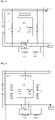
- a charging current flows from the battery cells 100 to the external system so that the charging current for starting the engine flows as illustrated in FIG. 3 when starting the engine, and, after starting the engine, the charging current flows from the external system to the battery cells 100 as illustrated in FIG. 4 so that the battery cells 100 may be charged by the engine.
- the charging FET is configured in a first path that is a main charging path as shown in FIG. 2 , and can be turned on/off by the charging FET control unit 600 described below so as to control a flow of the charging current.
- the current limiting unit includes first and second current limiting units 500a and 500b. As shown in FIG. 2 , the current limiting unit is configured in the second path that is different from the first path in which the charging FET 400 is configured, so as to consume a charging current of the battery cells 100 to thereby prevent the battery cells 100 from being overcharged.
- the second path in which the first and second current limiting units 500a and 500b are configured is formed in parallel with the first path that is the main path through which a charging current flows from an external system to the battery cells 100, so as to allow the charging current to flow when the charging FET 400 configured in the first path is turned off.
- the overvoltage determination unit 300 determines that the battery cells 100 have an overvoltage
- the charging current flows through the second path when the charging FET 400 is turned off by the charging FET control unit 600 described below.
- the charging current flowing through the battery cells 100 are consumed by the first and second current limiting units 500a and 500b configured in the second path so that the battery cells 100 may be prevented from being overcharged.
- the first and second current limiting units 500a and 500b are configured with bypass resistors. That is, since the first and second current limiting units 500a and 500b including bypass resistors consume the charging current of the battery cells 100 by as much as corresponding resistor values, the battery cells 100 may be prevented from being overcharged.
- the first path is the main path through which a charging current flows
- the second path is a path through which the charging current flows when the charging FET 400 configured in the first path is turned off, wherein the first and second current limiting units 500a and 500b including bypass resistors are configured in the second path to consume the charging current of the battery cells 100 to thereby prevent the battery cells 100 from being overcharged.
- ground GND of the second voltage measurement unit 200a of the voltage measurement unit 200 described above may be described as being positioned between the first and second current limiting units 500a and 500b including bypass resistors.
- the charging FET control unit may control on/off of the charging FET 400 according to a determination result from the overvoltage determination unit 300.
- the charging FET control unit may recognize that the battery cells 100 are in an overvoltage state, and may turn off the charging FET 400 in order to block the charging current flowing from an external system to the first path.
- the charging FET 400 may be turned on so as to allow the charging current from an external system to flow through the first path that is the main path.
- the charging FET control unit may turn on the charging FET 400.
- the system off signal output from the system off determination unit 700 indicates that an external system is turned off in a state in which the charging FET 400 is turned off due to determination of an overcharge state of the battery cells 100, and thus the charging FET 400 may be turned on again. Accordingly, the charging current may be allowed to flow from the battery cells 100 to an engine of an external system to enable engine start when starting the engine next time.
- the system off determination unit In a state in which the overvoltage determination unit 300 has determined that the battery cells 100 are in an overvoltage state, the system off determination unit detects whether there is a difference between the voltages respectively measured by the first and second voltage measurement units 200a and 200b of the voltage measurement unit 200, and determines that an external system is in an off state according to a result of the detection.
- the system off determination unit may include specific elements as below.
- the overvoltage state recognition unit may recognize an output of the overvoltage determination signal from the overvoltage determination unit 300 to recognize an overvoltage state of the battery cells 100.
- the overvoltage state recognition unit may determine that the battery cells 100 are in an overvoltage state, and may output an overvoltage state signal.
- the voltage difference detection unit detects whether there occurs a difference between the voltages respectively measured by the first and second voltage measurement units 200a and 200b of the voltage measurement unit 200.
- the voltage difference detection unit may receive the overvoltage state signal output from the overvoltage state recognition unit 710. Upon receiving the overvoltage state signal, the voltage difference detection unit compares the values of the voltages respectively measured by the first and second voltage measurement units 200a and 200b of the voltage measurement unit 200 after elapse of a predetermined time from the time of the input of the overvoltage state signal so as to detect whether there occurs a difference between the two voltages. When no difference is detected between the voltages of the first and second voltage measurement units 200a and 200b as a result of the comparison, the voltage difference detection unit may determine that an external system is turned off in an overvoltage state of the battery cells 100, and may output the system off signal to the charging FET control unit 600. Accordingly, the charging FET control unit 600 that has received the system off signal turns on the charging FET 400 so as to enable engine start by allowing a charging current to flow from the battery cells 100 to an engine when turning on power of an external system next time.
- the voltage difference detection unit detects whether there occurs a difference between the voltages of the first and second voltage measurement units 200a and 200b after elapse of the predetermined time from the time of the input of the overvoltage state signal, considering the time taken for the values of the voltages respectively measured by the first and second voltage measurement units 200a and 200b to become different since the charging current that was flowing through the first path flows through the second path when the charging FET 400 is turned off due to determination of an overcharge state. Accordingly, the voltage difference detection unit may more accurately detect a state in which the values of the voltages of the first and second voltage measurement units 200a and 200b become equal, i.e., there occurs no difference therebetween, and thus may accurately determine that a system has been turned off in an overvoltage state.
- the fact that the external system has been turned off may indicate that an electric vehicle or an electric two-wheeled vehicle is in a turned off state, and enabling the power of the external system to be turned on may indicate that next start is enabled in a turned off state.
- the present invention relates to a starting battery, which is mounted in an external system such as an electric vehicle or an electric two-wheeled vehicle to supply power for starting an engine, and is charged by the engine after the engine is started.
- an external system such as an electric vehicle or an electric two-wheeled vehicle to supply power for starting an engine
- the external system is turned off (ignition off) in a state in which the charging FET 400 is turned off, it is necessary to turn on the FET 400 again to enable engine start next time.
- the system off determination unit 700 determines that an external system is turned off, and outputs the system off signal to the charging FET control unit 600 to turn on the charging FET 400 so as to enable next start.
- the charging current may be supplied from the engine to the battery cells 100 so that the battery cells 100 may be charged as illustrated in FIG. 4 .
- the charging current flows through the first path that is the main path, and thus the flowing charging current is hardly limited by resistor, and the first and second voltage measurement units 200a and 200b measure the same voltage value.
- the values of the voltages measured by the first and second voltage measurement units 200a and 200b are the same, and in a state in which the charging current flows through the second path since the charging FET 400 is turned off as illustrated in FIG. 5 , i.e., in an overvoltage state, the ground GND of the second voltage measurement unit 200b is floated by the first and second current limiting units 500a and 500b configured in the second path, and thus there occurs a difference between the values of the voltages measured by the first and second voltage measurement units 200a and 200b.
- the voltage loaded on the first and second current limiting units 500a and 500b also changes, and thus the degree to which the ground GND of the second voltage measurement unit 200b is floated may vary.
- the present invention may use the above-described principle to determine that the external system is turned off by detecting that the voltages of the first and second voltage measurement units 200a and 200b are equal without having a difference in an overvoltage state.
- the state in which the external system is turned off may represent a state in which an engine is turned off.
- the present invention may recognize, without having a current sensor, the state in which the external system is turned off in an overvoltage state according to whether there occurs a difference between the values of the voltages measured by the first and second voltage measurement units 200a and 200b by providing a path in which the first and second current limiting units 500a and 500b including bypass resistors are configured and by connecting the grounds GND of the first and second voltage measurement units 200a and 200b to different positions, and thus enables a following control that enables next engine start, thereby improving price competitiveness and efficiency.
- the voltages measured by the first and second voltage measurement units 200a and 200b are required to have almost the same value to use the above-described principle, but the unit of distributed resistance of each voltage measurement unit is 10 to the power of 6 ohms, and the first and second current limiting units 500a and 500b, which are bypass resistors, have the unit of 10 to the power of 0 ohms, and thus there is a ten thousand times difference therebetween.
- the method of recognizing an off state of an external system according to the present invention may include the following steps.
- the voltage measurement step which is a step of measuring the voltage of the battery cells 100, may be performed by the first and second voltage measurement units 200a and 200b, each of which is configured with an ADC.
- the overvoltage determination step is a step of comparing the voltage measured in the voltage measurement step S100 with a preset reference voltage to determine whether the battery cells 100 are in an overvoltage state according to a result of the comparison. When the voltage measured in the voltage measurement step S100 exceeds the preset reference voltage, the battery cells 100 may be determined to be in an overvoltage state, and an overvoltage state signal may be output.
- This overvoltage determination step may be performed by the above-described overvoltage determination unit 300.
- the charging FET 400 configured in a first path that is a main charging path is controlled to be turned off in order to block a charging current flowing from an external system such as an electric vehicle or an electric two-wheeled vehicle to the battery cells 100 via the first path when the overvoltage determination signal is output since the battery cells 100 are determined to be in an overvoltage state in the overvoltage determination step S200.
- Overcharging may be prevented through this step since the charging current that was flowing from the external system to the battery cells 100 via the first path as illustrated in FIG. 4 flows through a second path in which the first and second current limiting units 500a and 500b including bypass resistors are configured as illustrated in FIG. 5 so that the current is limited by the first and second current limiting units 500a and 500b, thus reducing the charging current of the battery cells 100.
- This charging FET off control step may be performed by the charging FET control unit 600 that has received the overvoltage determination signal from the overvoltage determination unit 300.
- the voltage value sameness detection step when the charging current flowing from the external system to the battery cells 100 flows through the second path in which the first and second current limiting units 500a and 500b are configured through the charging FET off control step S300, the values of the voltages respectively measured by the first and second voltage measurement units 200a and 200b through the voltage measurement step S100 are compared to detect whether the two voltages are in the same state.
- the charging current flows through the second path in which the first and second current limiting units 500a and 500b are configured as illustrated in FIG. 5 .
- the first voltage measurement unit 200a has the cell ground GND
- the ground GND of the second voltage measurement unit 200b is positioned between the first and second current limiting units 500a and 500b
- the ground GND of the second voltage measurement unit 200b is floated by the first and second current limiting units 500a and 500b, causing occurrence of a difference between the values of the voltages respectively measured by the first and second voltage measurement units 200a and 200b.
- the values of the voltages measured by the first and second voltage measurement units 200a and 200b are different in the charging FET off control step S300, and in this state, it is detected that no difference occurs between the two voltages through the voltage difference detection step. Since this principle has been described in relation to a system configuration, detailed description is omitted.
- This voltage sameness detection step may be performed by the above-described system off determination unit 700.
- a state in which the system is turned off is determined according to a result of the voltage difference detection in the voltage value sameness detection step S400.
- a system off signal may be output to the charging FET control unit 600 so that the charging FET on control step S600 described below may be performed.
- the charging FET control unit 600 that has received the system off signal from the system off determination unit 700 since the system was determined to be turned off in the system off determination step S500 turns on the turned-off charging FET 400 configured in the first path.
- the charging current may be supplied from the battery cells 100 to the external system via the first path to enable engine start when starting the engine next time.
- the present invention may recognize a state in which the external system is turned off in an overvoltage state of a battery, i.e., may recognize a state in which the engine is turned off without having a current sensor as in the prior art, thereby enabling a control that enables next engine start.
- the effect of reducing the cost caused by providing a current sensor may be bring about, thereby improving the price competitiveness.
Landscapes
- Engineering & Computer Science (AREA)
- Power Engineering (AREA)
- Physics & Mathematics (AREA)
- General Physics & Mathematics (AREA)
- Life Sciences & Earth Sciences (AREA)
- Sustainable Development (AREA)
- Sustainable Energy (AREA)
- Transportation (AREA)
- Mechanical Engineering (AREA)
- Charge And Discharge Circuits For Batteries Or The Like (AREA)
- Secondary Cells (AREA)
- Control Of Charge By Means Of Generators (AREA)
Claims (11)
- Treibersystem einer Starterbatterie, wobei das Treibersystem umfasst:eine oder mehrere Batteriezellen (100);eine Spannungsmesseinheit (200), welche dazu eingerichtet ist, eine Spannung der Batteriezellen (200a) zu messen;
eine Überspannung-Bestimmungseinheit (300), welche dazu eingerichtet ist, die durch die Spannungsmesseinheit (200) gemessene Spannung mit einer voreingestellten Referenzspannung zu vergleichen, um gemäß einem Vergleichsergebnis zu bestimmen, ob sich die Batteriezellen in einem Überspannungszustand befinden;einen Lade-FET (400), welcher in einem ersten Pfad eingerichtet ist, welcher ein Hauptpfad ist, durch welchen ein Ladestrom zwischen den Batteriezellen und einem externen System fließt, um einen Fluss des Ladestroms zu steuern;eine erste und eine zweite Strombegrenzungseinheit (500a, 500b), welche in einem zweiten Pfad eingerichtet sind, durch welchen der Ladestrom von dem externen System zu den Batteriezellen fließt und welcher parallel zu dem ersten Pfad gebildet ist, um den Ladestrom der Batteriezellen zu verbrauchen;eine System-Aus-Bestimmungseinheit (700), welche dazu eingerichtet ist, auf Grundlage einer Änderung in einem Wert der durch die Spannungsmesseinheit gemessenen Spannung, einen Aus-Zustand des externen Systems zu bestimmen, mit welchem die Batteriezellen verbunden sind,eine Lade-FET-Steuerungseinheit (600), welche dazu eingerichtet ist, gemäß Bestimmungsergebnissen von der Überspannung-Bestimmungseinheit und der System-Aus-Bestimmungseinheit, ein Ein/Aus des Lade-FET zu steuern, welcher in dem ersten Pfad eingerichtet ist, wobei die Spannungsmesseinheit (200) eine erste Spannungsmesseinheit (200a) und eine zweite Spannungsmesseinheit (200b) umfasst, wobei Massen GND der ersten Spannungsmesseinheit und der zweiten Spannungsmesseinheit in verschiedenen Positionen festgelegt sind, wobei die Masse GND der ersten Spannungsmesseinheit in dem ersten Pfad positioniert ist und mit einer Zellen-Masse GND verbunden ist, und die Masse GND der zweiten Spannungsmesseinheit zwischen der ersten und der zweiten Strombegrenzungseinheit positioniert ist, welche in dem zweiten Pfad eingerichtet sind. - Treibersystem nach Anspruch 1,wobei die Überspannung-Bestimmungseinheit dazu eingerichtet ist, zu bestimmen, dass sich die Batteriezellen in dem Überspannungszustand befinden, wenn eine durch die erste Spannungsmesseinheit gemessene Spannung die voreingestellte Referenzspannung überschreitet, und ein Überspannung-Bestimmungssignal an die Lade-FET-Steuerungseinheit auszugeben, undwobei die Lade-FET-Steuerungseinheit dazu eingerichtet ist, den Lade-FET auf ein Empfangen des Überspannung-Bestimmungssignals von der Überspannung-Bestimmungseinheit hin, auszuschalten.
- Treibersystem nach Anspruch 2, wobei, wenn der Lade-FET durch die Lade-FET-Steuerungseinheit ausgeschaltet wird, der Ladestrom, welcher durch den ersten Pfad zu den Batteriezellen geflossen ist, durch den zweiten Pfad fliest.
- Treibersystem nach Anspruch 2, wobei die erste und die zweite Strombegrenzungseinheit, welche in dem zweiten Pfad eingerichtet sind, dazu eingerichtet sind, den durch den zweiten Pfad fliesenden Ladestrom zu verbrauchen, um zu verhindern, dass die Batteriezellen überladen werden.
- Treibersystem nach Anspruch 4, wobei, wenn der Ladestrom der Batteriezellen durch den zweiten Pfad fliest, die erste und die zweite Strombegrenzungseinheit dazu eingerichtet sind, ein Auftreten einer Differenz zwischen Werten von Spannungen zu bewirken, welche durch die erste bzw. die zweite Spannungsmesseinheit gemessen worden sind.
- Treibersystem nach Anspruch 5, wobei die System-Aus-Bestimmungseinheit umfasst:eine Überspannungszustand-Erkennungseinheit (710), welche dazu eingerichtet ist, den Überspannungszustand der Batteriezellen durch ein Detektieren zu erkennen, dass das Überspannung-Bestimmungssignal von der Überspannung-Bestimmungseinheit ausgegeben worden ist, und ein Überspannung-Zustandssignal auszugeben; undeine Spannungsdifferenz-Detektionseinheit (720), welche dazu eingerichtet ist, zu detektieren, wenn auf Grundlage des Überspannung-Zustandssignals, welches von der Überspannungszustand-Erkennungseinheit ausgeben worden ist, erkannt worden ist, dass sich die Batteriezellen in dem Überspannungszustand befinden, ob eine Differenz zwischen den Werten der Spannungen auftritt, welche durch die erste bzw. die zweite Spannungsmesseinheit gemessen worden sind, um einen Aus-Zustand des externen Systems zu bestimmen.
- Treibersystem nach Anspruch 6, wobei die Spannungsdifferenz-Detektionseinheit dazu eingerichtet ist, zu bestimmen, dass das externe System in einem Aus-Zustand ist, wenn detektiert wird, dass sich die Spannungen, welche durch die erste bzw. die zweite Spannungsmesseinheit gemessen worden sind, zu einem Zustand geändert haben, in welchem keine Differenz zwischen den Spannungen auftritt, und ein System-Aus-Signal an die Lade-FET-Steuerungseinheit auszugeben.
- Treibersystem nach Anspruch 7, wobei die Lade-FET-Steuerungseinheit dazu eingerichtet ist, auf ein Empfangen des System-Aus-Signals von der Spannungsdifferenz-Detektionseinheit hin, den Lade-FET einzuschalten.
- Treibersystem nach Anspruch 4, wobei jede aus der ersten und der zweiten Strombegrenzungseinheit mit einem Bypass-Widerstand eingerichtet ist.
- Verfahren zum Erkennen eines Aus-Zustands eines externen Systems in einem Überspannungszustand von Batteriezellen in einem System nach einem der Ansprüche 1 bis 9, wobei das Verfahren umfasst:einen Spannungsmessschritt (S100), in welchem die erste und die zweite Spannungsmesseinheit eine Spannung jeder der Batteriezellen messen;einen Überspannung-Bestimmungsschritt (S200), in welchem die Überspannung-Bestimmungseinheit die durch die erste Spannungsmesseinheit mittels des Spannungsmessschritts gemessene Spannung mit einer voreingestellten Referenzspannung vergleicht, um zu bestimmen, ob die gemessene Spannung die voreingestellte Referenzspannung überschreitet, um gemäß einem Vergleichsergebnis zu bestimmen, ob sich die Batteriezellen in dem Überspannungszustand befinden;einen Lade-FET-Aus-Steuerungsschritt (S300), in welchem, wenn mittels des Überspannung-Bestimmungsschritts bestimmt worden ist, dass sich die Batteriezellen in dem Überspannungszustand befinden, die Lade-FET-Steuerungseinheit den Lade-FET ausschaltet, welcher in dem ersten Pfad eingerichtet ist, um den Ladestrom zu steuern, welcher von dem externen System zu den Batteriezellen fließt;einen Spannungswert-Gleichheit-Detektionsschritt (S400), in welchem, die System-Aus-Bestimmungseinheit detektiert, ob die Spannungen, welche durch die erste bzw. die zweite Spannungsmesseinheit gemessen worden sind, den gleichen Wert aufweisen, wenn der Lade-FET, welcher in dem ersten Pfad eingerichtet ist, mittels des Lade-FET-Aus-Steuerungsschritts ausgeschaltet wird;einen System-Aus-Bestimmungsschritt (S500), in welchem, wenn in dem Spannungswert-Gleichheit-Detektionsschritt detektiert worden ist, dass die Spannungen, welche durch die erste bzw. die zweite Spannungsmesseinheit gemessen worden sind, den gleichen Wert aufweisen, bestimmt wird, dass sich das externe System in dem Aus-Zustand befindet; undeinen Lade-FET-Ein-Steuerungsschritt (S600), in welchem, wenn in dem System-Aus-Bestimmungsschritt bestimmt worden ist, dass sich das externe System in dem Aus-Zustand befindet, die Lade-FET-Steuerungseinheit den Lade-FET einschaltet, welcher in dem ersten Pfad konfiguriert ist.
- Verfahren nach Anspruch 10, wobei in dem Lade-FET-Aus-Steuerungsschritt, wenn der Ladestrom durch den zweiten Pfad fliest, da der in dem ersten Pfad eingerichtete Lade-FET ausgeschaltet ist, die Werte der Spannungen, welche durch die erste bzw. die zweite Spannungsmesseinheit gemessen werden, aufgrund der ersten und der zweiten Strombegrenzungseinheit, welche in dem zweiten Pfad bereitgestellt sind, verschieden voneinander sind.
Applications Claiming Priority (2)
| Application Number | Priority Date | Filing Date | Title |
|---|---|---|---|
| KR1020180148371A KR102316486B1 (ko) | 2018-11-27 | 2018-11-27 | 시동용 배터리의 구동 시스템 및 이를 이용한 외부 시스템 오프 상태 인식 방법 |
| PCT/KR2019/012462 WO2020111481A1 (ko) | 2018-11-27 | 2019-09-25 | 시동용 배터리의 구동 시스템 및 이를 이용한 외부 시스템 오프 상태 인식 방법 |
Publications (3)
| Publication Number | Publication Date |
|---|---|
| EP3708405A1 EP3708405A1 (de) | 2020-09-16 |
| EP3708405A4 EP3708405A4 (de) | 2020-09-16 |
| EP3708405B1 true EP3708405B1 (de) | 2022-06-15 |
Family
ID=70852843
Family Applications (1)
| Application Number | Title | Priority Date | Filing Date |
|---|---|---|---|
| EP19890914.5A Active EP3708405B1 (de) | 2018-11-27 | 2019-09-25 | Startbatterie-antriebssystem und verfahren zur erkennung des aus-zustandes eines externen systems damit |
Country Status (6)
| Country | Link |
|---|---|
| US (1) | US11437837B2 (de) |
| EP (1) | EP3708405B1 (de) |
| JP (1) | JP7062172B2 (de) |
| KR (1) | KR102316486B1 (de) |
| CN (1) | CN111527004B (de) |
| WO (1) | WO2020111481A1 (de) |
Families Citing this family (1)
| Publication number | Priority date | Publication date | Assignee | Title |
|---|---|---|---|---|
| US12487648B2 (en) * | 2022-03-10 | 2025-12-02 | Microsoft Technology Licensing, Llc | Adaptive power control for an electronic device |
Family Cites Families (37)
| Publication number | Priority date | Publication date | Assignee | Title |
|---|---|---|---|---|
| JPH0638400A (ja) | 1992-07-17 | 1994-02-10 | Hitachi Ltd | 小型情報処理装置のバッテリ装置 |
| JPH06305126A (ja) | 1993-04-22 | 1994-11-01 | Brother Ind Ltd | インクジェット方式の印刷装置 |
| US5557188A (en) * | 1994-02-01 | 1996-09-17 | Sun Microsystems, Inc. | Smart battery system and interface |
| JP3539598B2 (ja) * | 1995-11-10 | 2004-07-07 | 株式会社デンソー | 搭載用電源システム |
| JPH1062102A (ja) | 1996-08-20 | 1998-03-06 | Eitaro Sakaguchi | 内径を計る巻尺 |
| JPH10271705A (ja) | 1997-03-28 | 1998-10-09 | Mitsubishi Electric Corp | 電源回路 |
| JP2001327001A (ja) * | 2000-05-11 | 2001-11-22 | Toyota Motor Corp | ハイブリッド車両におけるシステムリレーの診断装置およびその方法 |
| JP2001345699A (ja) | 2000-06-02 | 2001-12-14 | Nec Microsystems Ltd | A/d変換器の試験回路及びその試験方法 |
| KR100621072B1 (ko) * | 2004-08-09 | 2006-09-13 | 엘지이노텍 주식회사 | 과전류 보호모듈 |
| JP4539431B2 (ja) | 2005-05-11 | 2010-09-08 | トヨタ自動車株式会社 | 電源制御装置 |
| JP4375318B2 (ja) * | 2005-10-12 | 2009-12-02 | ソニー株式会社 | バッテリー装置 |
| KR100839382B1 (ko) * | 2006-10-16 | 2008-06-20 | 삼성에스디아이 주식회사 | 배터리 관리 시스템 및 그의 구동 방법 |
| KR101406542B1 (ko) | 2007-08-10 | 2014-06-11 | 엘지전자 주식회사 | PoE를 이용하는 휴대용 컴퓨터시스템과 그 전원장치 및전원제어방법 |
| KR100957144B1 (ko) * | 2007-11-07 | 2010-05-11 | 현대자동차주식회사 | 차량의 발전 제어장치 및 방법 |
| CN101557118B (zh) * | 2008-04-09 | 2012-05-30 | 鹏智科技(深圳)有限公司 | 二次电池的充电控制电路 |
| JP5233725B2 (ja) * | 2009-02-16 | 2013-07-10 | 日産自動車株式会社 | 電動車両の制御装置 |
| JP2010246225A (ja) * | 2009-04-03 | 2010-10-28 | Sony Corp | 電池パックおよび充電方法 |
| JP2011101517A (ja) | 2009-11-06 | 2011-05-19 | Sanyo Electric Co Ltd | パック電池 |
| JP2011135657A (ja) * | 2009-12-22 | 2011-07-07 | Sanyo Electric Co Ltd | バッテリシステム及びこれを備える車両並びにバッテリシステムの電流制限状態検出方法 |
| JP5544923B2 (ja) * | 2010-02-24 | 2014-07-09 | セイコーエプソン株式会社 | 保護回路および電子機器 |
| KR101413251B1 (ko) * | 2010-08-13 | 2014-06-27 | 주식회사 엘지화학 | 2차 전지 관리 장치 |
| TWM402554U (en) * | 2010-11-10 | 2011-04-21 | Richtek Technology Corp | Charger circuit |
| US8541981B2 (en) * | 2010-11-10 | 2013-09-24 | Texas Instruments Incorporated | Low-voltage dual-power-path management architecture for rechargeable battery monitoring solutions |
| JP5683372B2 (ja) * | 2011-04-27 | 2015-03-11 | デクセリアルズ株式会社 | 充放電制御装置、バッテリパック、電気機器、及び、充放電制御方法 |
| CN102810882A (zh) * | 2011-06-02 | 2012-12-05 | 魏培伦 | 一种量测电池电压的电路和方法 |
| JP6068192B2 (ja) | 2013-02-28 | 2017-01-25 | 本田技研工業株式会社 | バッテリ状態推定装置及び車両の制御システム |
| JP6305126B2 (ja) * | 2014-03-12 | 2018-04-04 | マクセルホールディングス株式会社 | 予備充放電機能を有する電池パック |
| KR20160099357A (ko) * | 2015-02-12 | 2016-08-22 | 삼성에스디아이 주식회사 | 배터리 팩 및 이를 포함하는 배터리 시스템 |
| WO2017133400A2 (zh) * | 2016-02-05 | 2017-08-10 | 广东欧珀移动通信有限公司 | 适配器和充电控制方法 |
| JP6741211B2 (ja) | 2016-08-05 | 2020-08-19 | 株式会社Gsユアサ | 蓄電装置、車両、及び蓄電装置の充電制御方法 |
| KR102222119B1 (ko) | 2016-08-11 | 2021-03-03 | 삼성에스디아이 주식회사 | 배터리 팩 |
| JP6683819B2 (ja) * | 2016-09-21 | 2020-04-22 | 株式会社エンビジョンAescジャパン | 電源システム |
| CN106379188A (zh) * | 2016-09-30 | 2017-02-08 | 华南理工大学 | 一种电动汽车动力电池能量管理系统及安全防护方法 |
| CN106537720B (zh) * | 2016-10-21 | 2020-06-19 | 北京小米移动软件有限公司 | 充电方法及电子设备 |
| KR20180045954A (ko) * | 2016-10-26 | 2018-05-08 | 현대자동차주식회사 | 배터리 관리 시스템 및 그 제어방법 |
| JP6724726B2 (ja) * | 2016-11-02 | 2020-07-15 | トヨタ自動車株式会社 | 電力供給装置 |
| CN108656976B (zh) * | 2017-04-01 | 2021-04-13 | 北京海博思创科技股份有限公司 | 电池管理系统 |
-
2018
- 2018-11-27 KR KR1020180148371A patent/KR102316486B1/ko active Active
-
2019
- 2019-09-25 CN CN201980006831.0A patent/CN111527004B/zh active Active
- 2019-09-25 JP JP2020533598A patent/JP7062172B2/ja active Active
- 2019-09-25 US US16/958,941 patent/US11437837B2/en active Active
- 2019-09-25 EP EP19890914.5A patent/EP3708405B1/de active Active
- 2019-09-25 WO PCT/KR2019/012462 patent/WO2020111481A1/ko not_active Ceased
Also Published As
| Publication number | Publication date |
|---|---|
| KR20200062687A (ko) | 2020-06-04 |
| KR102316486B1 (ko) | 2021-10-22 |
| CN111527004B (zh) | 2023-06-27 |
| EP3708405A1 (de) | 2020-09-16 |
| US11437837B2 (en) | 2022-09-06 |
| WO2020111481A1 (ko) | 2020-06-04 |
| EP3708405A4 (de) | 2020-09-16 |
| JP7062172B2 (ja) | 2022-05-06 |
| US20200343759A1 (en) | 2020-10-29 |
| JP2021510055A (ja) | 2021-04-08 |
| CN111527004A (zh) | 2020-08-11 |
Similar Documents
| Publication | Publication Date | Title |
|---|---|---|
| KR102345506B1 (ko) | 배터리 팩, 배터리 팩의 충전 제어 방법, 및 배터리 팩을 포함하는 차량 | |
| KR101255248B1 (ko) | 배터리 관리 시스템 및 이의 제어 방법 | |
| US10298011B2 (en) | Electric storage apparatus and power path switch apparatus | |
| KR101350370B1 (ko) | 배터리팩 제어 장치 | |
| EP2416166B1 (de) | Verfahren und vorrichtung zur diagnostizierung von anomalien einer strommesseinheit eines batteriepacks | |
| KR101217074B1 (ko) | 배터리 관리 시스템 | |
| CN100593276C (zh) | 用于电源系统的监视装置 | |
| US10351084B2 (en) | Power supply control system | |
| US20150056479A1 (en) | method for connecting battery cells in a battery, battery, and monitoring device | |
| US20120161709A1 (en) | Secondary-battery control apparatus | |
| JP5297729B2 (ja) | 電圧検出装置 | |
| US20120106013A1 (en) | Current sense circuit and battery over-current protection controller | |
| EP3598602B1 (de) | Überspannungsschutzsystem und -verfahren mit ausgleichswiderstand | |
| US20160056646A1 (en) | Overcharge protection apparatus with minimized power consumption | |
| KR20130101235A (ko) | 에너지를 재사용하는 배터리 밸런싱 시스템 및 배터리 밸런싱 방법 | |
| EP3708405B1 (de) | Startbatterie-antriebssystem und verfahren zur erkennung des aus-zustandes eines externen systems damit | |
| KR101073277B1 (ko) | 하이브리드 전기 자동차용 배터리 팩의 셀 밸런싱 방법 및이를 위한 장치 | |
| KR102637310B1 (ko) | 배터리 셀 열화 상태 진단 방법 및 이를 이용한 배터리 팩 | |
| US7612540B2 (en) | Lithium-ion battery diagnostic and prognostic techniques | |
| JP2000356656A (ja) | 電池の端子電圧検出装置 | |
| JP2006105641A (ja) | バックアップ電源システム | |
| JP2010011631A (ja) | 電源装置 | |
| JP7647688B2 (ja) | 制御装置、制御方法、及び制御プログラム | |
| JP2007267559A (ja) | 2次電池の充電方法 | |
| CN103424646A (zh) | 车辆电气系统故障检测 |
Legal Events
| Date | Code | Title | Description |
|---|---|---|---|
| STAA | Information on the status of an ep patent application or granted ep patent |
Free format text: STATUS: THE INTERNATIONAL PUBLICATION HAS BEEN MADE |
|
| PUAI | Public reference made under article 153(3) epc to a published international application that has entered the european phase |
Free format text: ORIGINAL CODE: 0009012 |
|
| STAA | Information on the status of an ep patent application or granted ep patent |
Free format text: STATUS: REQUEST FOR EXAMINATION WAS MADE |
|
| 17P | Request for examination filed |
Effective date: 20200611 |
|
| A4 | Supplementary search report drawn up and despatched |
Effective date: 20200810 |
|
| AK | Designated contracting states |
Kind code of ref document: A1 Designated state(s): AL AT BE BG CH CY CZ DE DK EE ES FI FR GB GR HR HU IE IS IT LI LT LU LV MC MK MT NL NO PL PT RO RS SE SI SK SM TR |
|
| AX | Request for extension of the european patent |
Extension state: BA ME |
|
| GRAP | Despatch of communication of intention to grant a patent |
Free format text: ORIGINAL CODE: EPIDOSNIGR1 |
|
| STAA | Information on the status of an ep patent application or granted ep patent |
Free format text: STATUS: GRANT OF PATENT IS INTENDED |
|
| RAP1 | Party data changed (applicant data changed or rights of an application transferred) |
Owner name: LG ENERGY SOLUTION LTD. |
|
| INTG | Intention to grant announced |
Effective date: 20220110 |
|
| DAV | Request for validation of the european patent (deleted) | ||
| DAX | Request for extension of the european patent (deleted) | ||
| RAP3 | Party data changed (applicant data changed or rights of an application transferred) |
Owner name: LG ENERGY SOLUTION, LTD. |
|
| GRAS | Grant fee paid |
Free format text: ORIGINAL CODE: EPIDOSNIGR3 |
|
| GRAA | (expected) grant |
Free format text: ORIGINAL CODE: 0009210 |
|
| STAA | Information on the status of an ep patent application or granted ep patent |
Free format text: STATUS: THE PATENT HAS BEEN GRANTED |
|
| AK | Designated contracting states |
Kind code of ref document: B1 Designated state(s): AL AT BE BG CH CY CZ DE DK EE ES FI FR GB GR HR HU IE IS IT LI LT LU LV MC MK MT NL NO PL PT RO RS SE SI SK SM TR |
|
| REG | Reference to a national code |
Ref country code: CH Ref legal event code: EP Ref country code: GB Ref legal event code: FG4D |
|
| REG | Reference to a national code |
Ref country code: IE Ref legal event code: FG4D |
|
| REG | Reference to a national code |
Ref country code: DE Ref legal event code: R096 Ref document number: 602019016031 Country of ref document: DE |
|
| REG | Reference to a national code |
Ref country code: AT Ref legal event code: REF Ref document number: 1498179 Country of ref document: AT Kind code of ref document: T Effective date: 20220715 |
|
| REG | Reference to a national code |
Ref country code: LT Ref legal event code: MG9D |
|
| REG | Reference to a national code |
Ref country code: NL Ref legal event code: MP Effective date: 20220615 |
|
| PG25 | Lapsed in a contracting state [announced via postgrant information from national office to epo] |
Ref country code: SE Free format text: LAPSE BECAUSE OF FAILURE TO SUBMIT A TRANSLATION OF THE DESCRIPTION OR TO PAY THE FEE WITHIN THE PRESCRIBED TIME-LIMIT Effective date: 20220615 Ref country code: NO Free format text: LAPSE BECAUSE OF FAILURE TO SUBMIT A TRANSLATION OF THE DESCRIPTION OR TO PAY THE FEE WITHIN THE PRESCRIBED TIME-LIMIT Effective date: 20220915 Ref country code: LT Free format text: LAPSE BECAUSE OF FAILURE TO SUBMIT A TRANSLATION OF THE DESCRIPTION OR TO PAY THE FEE WITHIN THE PRESCRIBED TIME-LIMIT Effective date: 20220615 Ref country code: HR Free format text: LAPSE BECAUSE OF FAILURE TO SUBMIT A TRANSLATION OF THE DESCRIPTION OR TO PAY THE FEE WITHIN THE PRESCRIBED TIME-LIMIT Effective date: 20220615 Ref country code: GR Free format text: LAPSE BECAUSE OF FAILURE TO SUBMIT A TRANSLATION OF THE DESCRIPTION OR TO PAY THE FEE WITHIN THE PRESCRIBED TIME-LIMIT Effective date: 20220916 Ref country code: FI Free format text: LAPSE BECAUSE OF FAILURE TO SUBMIT A TRANSLATION OF THE DESCRIPTION OR TO PAY THE FEE WITHIN THE PRESCRIBED TIME-LIMIT Effective date: 20220615 Ref country code: BG Free format text: LAPSE BECAUSE OF FAILURE TO SUBMIT A TRANSLATION OF THE DESCRIPTION OR TO PAY THE FEE WITHIN THE PRESCRIBED TIME-LIMIT Effective date: 20220915 |
|
| REG | Reference to a national code |
Ref country code: AT Ref legal event code: MK05 Ref document number: 1498179 Country of ref document: AT Kind code of ref document: T Effective date: 20220615 |
|
| PG25 | Lapsed in a contracting state [announced via postgrant information from national office to epo] |
Ref country code: RS Free format text: LAPSE BECAUSE OF FAILURE TO SUBMIT A TRANSLATION OF THE DESCRIPTION OR TO PAY THE FEE WITHIN THE PRESCRIBED TIME-LIMIT Effective date: 20220615 Ref country code: LV Free format text: LAPSE BECAUSE OF FAILURE TO SUBMIT A TRANSLATION OF THE DESCRIPTION OR TO PAY THE FEE WITHIN THE PRESCRIBED TIME-LIMIT Effective date: 20220615 |
|
| PG25 | Lapsed in a contracting state [announced via postgrant information from national office to epo] |
Ref country code: NL Free format text: LAPSE BECAUSE OF FAILURE TO SUBMIT A TRANSLATION OF THE DESCRIPTION OR TO PAY THE FEE WITHIN THE PRESCRIBED TIME-LIMIT Effective date: 20220615 |
|
| PG25 | Lapsed in a contracting state [announced via postgrant information from national office to epo] |
Ref country code: SM Free format text: LAPSE BECAUSE OF FAILURE TO SUBMIT A TRANSLATION OF THE DESCRIPTION OR TO PAY THE FEE WITHIN THE PRESCRIBED TIME-LIMIT Effective date: 20220615 Ref country code: SK Free format text: LAPSE BECAUSE OF FAILURE TO SUBMIT A TRANSLATION OF THE DESCRIPTION OR TO PAY THE FEE WITHIN THE PRESCRIBED TIME-LIMIT Effective date: 20220615 Ref country code: RO Free format text: LAPSE BECAUSE OF FAILURE TO SUBMIT A TRANSLATION OF THE DESCRIPTION OR TO PAY THE FEE WITHIN THE PRESCRIBED TIME-LIMIT Effective date: 20220615 Ref country code: PT Free format text: LAPSE BECAUSE OF FAILURE TO SUBMIT A TRANSLATION OF THE DESCRIPTION OR TO PAY THE FEE WITHIN THE PRESCRIBED TIME-LIMIT Effective date: 20221017 Ref country code: ES Free format text: LAPSE BECAUSE OF FAILURE TO SUBMIT A TRANSLATION OF THE DESCRIPTION OR TO PAY THE FEE WITHIN THE PRESCRIBED TIME-LIMIT Effective date: 20220615 Ref country code: EE Free format text: LAPSE BECAUSE OF FAILURE TO SUBMIT A TRANSLATION OF THE DESCRIPTION OR TO PAY THE FEE WITHIN THE PRESCRIBED TIME-LIMIT Effective date: 20220615 Ref country code: CZ Free format text: LAPSE BECAUSE OF FAILURE TO SUBMIT A TRANSLATION OF THE DESCRIPTION OR TO PAY THE FEE WITHIN THE PRESCRIBED TIME-LIMIT Effective date: 20220615 Ref country code: AT Free format text: LAPSE BECAUSE OF FAILURE TO SUBMIT A TRANSLATION OF THE DESCRIPTION OR TO PAY THE FEE WITHIN THE PRESCRIBED TIME-LIMIT Effective date: 20220615 |
|
| PG25 | Lapsed in a contracting state [announced via postgrant information from national office to epo] |
Ref country code: PL Free format text: LAPSE BECAUSE OF FAILURE TO SUBMIT A TRANSLATION OF THE DESCRIPTION OR TO PAY THE FEE WITHIN THE PRESCRIBED TIME-LIMIT Effective date: 20220615 Ref country code: IS Free format text: LAPSE BECAUSE OF FAILURE TO SUBMIT A TRANSLATION OF THE DESCRIPTION OR TO PAY THE FEE WITHIN THE PRESCRIBED TIME-LIMIT Effective date: 20221015 |
|
| REG | Reference to a national code |
Ref country code: DE Ref legal event code: R097 Ref document number: 602019016031 Country of ref document: DE |
|
| PG25 | Lapsed in a contracting state [announced via postgrant information from national office to epo] |
Ref country code: AL Free format text: LAPSE BECAUSE OF FAILURE TO SUBMIT A TRANSLATION OF THE DESCRIPTION OR TO PAY THE FEE WITHIN THE PRESCRIBED TIME-LIMIT Effective date: 20220615 |
|
| PLBE | No opposition filed within time limit |
Free format text: ORIGINAL CODE: 0009261 |
|
| STAA | Information on the status of an ep patent application or granted ep patent |
Free format text: STATUS: NO OPPOSITION FILED WITHIN TIME LIMIT |
|
| PG25 | Lapsed in a contracting state [announced via postgrant information from national office to epo] |
Ref country code: MC Free format text: LAPSE BECAUSE OF FAILURE TO SUBMIT A TRANSLATION OF THE DESCRIPTION OR TO PAY THE FEE WITHIN THE PRESCRIBED TIME-LIMIT Effective date: 20220615 Ref country code: DK Free format text: LAPSE BECAUSE OF FAILURE TO SUBMIT A TRANSLATION OF THE DESCRIPTION OR TO PAY THE FEE WITHIN THE PRESCRIBED TIME-LIMIT Effective date: 20220615 |
|
| REG | Reference to a national code |
Ref country code: CH Ref legal event code: PL |
|
| 26N | No opposition filed |
Effective date: 20230316 |
|
| REG | Reference to a national code |
Ref country code: BE Ref legal event code: MM Effective date: 20220930 |
|
| PG25 | Lapsed in a contracting state [announced via postgrant information from national office to epo] |
Ref country code: SI Free format text: LAPSE BECAUSE OF FAILURE TO SUBMIT A TRANSLATION OF THE DESCRIPTION OR TO PAY THE FEE WITHIN THE PRESCRIBED TIME-LIMIT Effective date: 20220615 |
|
| P01 | Opt-out of the competence of the unified patent court (upc) registered |
Effective date: 20230512 |
|
| PG25 | Lapsed in a contracting state [announced via postgrant information from national office to epo] |
Ref country code: LU Free format text: LAPSE BECAUSE OF NON-PAYMENT OF DUE FEES Effective date: 20220925 |
|
| PG25 | Lapsed in a contracting state [announced via postgrant information from national office to epo] |
Ref country code: LI Free format text: LAPSE BECAUSE OF NON-PAYMENT OF DUE FEES Effective date: 20220930 Ref country code: IE Free format text: LAPSE BECAUSE OF NON-PAYMENT OF DUE FEES Effective date: 20220925 Ref country code: CH Free format text: LAPSE BECAUSE OF NON-PAYMENT OF DUE FEES Effective date: 20220930 |
|
| PG25 | Lapsed in a contracting state [announced via postgrant information from national office to epo] |
Ref country code: BE Free format text: LAPSE BECAUSE OF NON-PAYMENT OF DUE FEES Effective date: 20220930 |
|
| PG25 | Lapsed in a contracting state [announced via postgrant information from national office to epo] |
Ref country code: IT Free format text: LAPSE BECAUSE OF FAILURE TO SUBMIT A TRANSLATION OF THE DESCRIPTION OR TO PAY THE FEE WITHIN THE PRESCRIBED TIME-LIMIT Effective date: 20220615 |
|
| PG25 | Lapsed in a contracting state [announced via postgrant information from national office to epo] |
Ref country code: CY Free format text: LAPSE BECAUSE OF FAILURE TO SUBMIT A TRANSLATION OF THE DESCRIPTION OR TO PAY THE FEE WITHIN THE PRESCRIBED TIME-LIMIT Effective date: 20220615 |
|
| PG25 | Lapsed in a contracting state [announced via postgrant information from national office to epo] |
Ref country code: MK Free format text: LAPSE BECAUSE OF FAILURE TO SUBMIT A TRANSLATION OF THE DESCRIPTION OR TO PAY THE FEE WITHIN THE PRESCRIBED TIME-LIMIT Effective date: 20220615 Ref country code: HU Free format text: LAPSE BECAUSE OF FAILURE TO SUBMIT A TRANSLATION OF THE DESCRIPTION OR TO PAY THE FEE WITHIN THE PRESCRIBED TIME-LIMIT; INVALID AB INITIO Effective date: 20190925 |
|
| PG25 | Lapsed in a contracting state [announced via postgrant information from national office to epo] |
Ref country code: TR Free format text: LAPSE BECAUSE OF FAILURE TO SUBMIT A TRANSLATION OF THE DESCRIPTION OR TO PAY THE FEE WITHIN THE PRESCRIBED TIME-LIMIT Effective date: 20220615 |
|
| PG25 | Lapsed in a contracting state [announced via postgrant information from national office to epo] |
Ref country code: MT Free format text: LAPSE BECAUSE OF FAILURE TO SUBMIT A TRANSLATION OF THE DESCRIPTION OR TO PAY THE FEE WITHIN THE PRESCRIBED TIME-LIMIT Effective date: 20220615 |
|
| PG25 | Lapsed in a contracting state [announced via postgrant information from national office to epo] |
Ref country code: BG Free format text: LAPSE BECAUSE OF FAILURE TO SUBMIT A TRANSLATION OF THE DESCRIPTION OR TO PAY THE FEE WITHIN THE PRESCRIBED TIME-LIMIT Effective date: 20220615 |
|
| PG25 | Lapsed in a contracting state [announced via postgrant information from national office to epo] |
Ref country code: BG Free format text: LAPSE BECAUSE OF FAILURE TO SUBMIT A TRANSLATION OF THE DESCRIPTION OR TO PAY THE FEE WITHIN THE PRESCRIBED TIME-LIMIT Effective date: 20220615 |
|
| PGFP | Annual fee paid to national office [announced via postgrant information from national office to epo] |
Ref country code: DE Payment date: 20250820 Year of fee payment: 7 |
|
| PGFP | Annual fee paid to national office [announced via postgrant information from national office to epo] |
Ref country code: GB Payment date: 20250820 Year of fee payment: 7 |
|
| PGFP | Annual fee paid to national office [announced via postgrant information from national office to epo] |
Ref country code: FR Payment date: 20250821 Year of fee payment: 7 |