EP3707096B1 - Transport system and methods - Google Patents
Transport system and methods Download PDFInfo
- Publication number
- EP3707096B1 EP3707096B1 EP18804902.7A EP18804902A EP3707096B1 EP 3707096 B1 EP3707096 B1 EP 3707096B1 EP 18804902 A EP18804902 A EP 18804902A EP 3707096 B1 EP3707096 B1 EP 3707096B1
- Authority
- EP
- European Patent Office
- Prior art keywords
- build
- workpiece
- transport
- fixture
- workstation
- Prior art date
- Legal status (The legal status is an assumption and is not a legal conclusion. Google has not performed a legal analysis and makes no representation as to the accuracy of the status listed.)
- Active
Links
Images






Classifications
-
- B—PERFORMING OPERATIONS; TRANSPORTING
- B65—CONVEYING; PACKING; STORING; HANDLING THIN OR FILAMENTARY MATERIAL
- B65G—TRANSPORT OR STORAGE DEVICES, e.g. CONVEYORS FOR LOADING OR TIPPING, SHOP CONVEYOR SYSTEMS OR PNEUMATIC TUBE CONVEYORS
- B65G35/00—Mechanical conveyors not otherwise provided for
- B65G35/06—Mechanical conveyors not otherwise provided for comprising a load-carrier moving along a path, e.g. a closed path, and adapted to be engaged by any one of a series of traction elements spaced along the path
-
- B—PERFORMING OPERATIONS; TRANSPORTING
- B62—LAND VEHICLES FOR TRAVELLING OTHERWISE THAN ON RAILS
- B62D—MOTOR VEHICLES; TRAILERS
- B62D65/00—Designing, manufacturing, e.g. assembling, facilitating disassembly, or structurally modifying motor vehicles or trailers, not otherwise provided for
- B62D65/02—Joining sub-units or components to, or positioning sub-units or components with respect to, body shell or other sub-units or components
- B62D65/18—Transportation, conveyor or haulage systems specially adapted for motor vehicle or trailer assembly lines
-
- B—PERFORMING OPERATIONS; TRANSPORTING
- B66—HOISTING; LIFTING; HAULING
- B66F—HOISTING, LIFTING, HAULING OR PUSHING, NOT OTHERWISE PROVIDED FOR, e.g. DEVICES WHICH APPLY A LIFTING OR PUSHING FORCE DIRECTLY TO THE SURFACE OF A LOAD
- B66F9/00—Devices for lifting or lowering bulky or heavy goods for loading or unloading purposes
- B66F9/06—Devices for lifting or lowering bulky or heavy goods for loading or unloading purposes movable, with their loads, on wheels or the like, e.g. fork-lift trucks
- B66F9/065—Devices for lifting or lowering bulky or heavy goods for loading or unloading purposes movable, with their loads, on wheels or the like, e.g. fork-lift trucks non-masted
-
- B—PERFORMING OPERATIONS; TRANSPORTING
- B65—CONVEYING; PACKING; STORING; HANDLING THIN OR FILAMENTARY MATERIAL
- B65G—TRANSPORT OR STORAGE DEVICES, e.g. CONVEYORS FOR LOADING OR TIPPING, SHOP CONVEYOR SYSTEMS OR PNEUMATIC TUBE CONVEYORS
- B65G2201/00—Indexing codes relating to handling devices, e.g. conveyors, characterised by the type of product or load being conveyed or handled
- B65G2201/02—Articles
- B65G2201/0267—Pallets
-
- B—PERFORMING OPERATIONS; TRANSPORTING
- B65—CONVEYING; PACKING; STORING; HANDLING THIN OR FILAMENTARY MATERIAL
- B65G—TRANSPORT OR STORAGE DEVICES, e.g. CONVEYORS FOR LOADING OR TIPPING, SHOP CONVEYOR SYSTEMS OR PNEUMATIC TUBE CONVEYORS
- B65G2201/00—Indexing codes relating to handling devices, e.g. conveyors, characterised by the type of product or load being conveyed or handled
- B65G2201/02—Articles
- B65G2201/0294—Vehicle bodies
Definitions
- This disclosure relates to transport systems for exemplary use in moving or transporting components, holding fixtures, partially assembled products and other items or equipment in an industrial or logistics complex or assembly line.
- Examples of overhead conveyor systems including devices for lowering components and subassemblies supported by the overhead conveyor downward into fixtures for processing, are described in one or more of US Patent Numbers 6,719,122 ; 6,557,690 ; 6,564,440 ; and 6,799,673 .
- AGV's automated guided vehicles
- AGC's automated guided carts
- AGV's generally include sophisticated guidance devices, for example laser scanners, proximity sensors, GPS and the devices to guide the AGV along a predetermined course.
- AGV's are generally more accurate in following a preprogrammed path or course and stopping at a predetermined location, for example +/- ten (10) millimeters (mm), from a target position.
- AGV's are expensive.
- AGC's and other devices are less accurate in their maneuverability and accuracy, but are considerably less expensive than AGV's.
- AGV's Even with the increased accuracy of AGV's (+/- 10 mm), modern AGV's are still not accurate enough to use for positioning components and partially-assembled structures for modern precision assembly workstations or assembly cell operations.
- the use of AGV's were largely limited to moving components and equipment from one position to a predetermined destination. At the destination, a transfer of the partially-assembled component from the AGV to a fixture or other device directly used for the assembly process was needed. In such instances, a manipulator, for example by a robot, was required which requires additional infrastructure, floor space, time used to transfer, and increases costs to produce the final saleable product.
- An assembly transport system is also known from WO 2011/053681 A1 , which discloses the preamble of claim 1.
- AGVs or AGV-like autonomous devices
- auxiliary, or dedicated, equipment and methods such as powered manipulator devices such as programmable robots and/or supplemental positioning devices.
- the invention is directed to a transport system according to claim 1 and a method according to claim 14. Preferred embodiments are laid out in the dependent claims.
- the transport system is useful in transporting a component in the form of a progressively assembled workpiece to a workstation and then positioning the workpiece at a workstation for precision work on the workpiece.
- the system 10 is used to transport and position automobile body components and subassemblies that are sequentially built through sequentially-positioned workstations along an assembly line. It is understood that system 10 may be used in other applications, for example, in manufacturing processes, or other assembly processes, and other applications where products or articles are transferred through multi-station process lines.
- the transferred component or workpiece may include one or more of raw materials, hardware, consumable assembly supplies or materials, fasteners, partially or wholly completed parts or subassemblies, assembly or manufacturing equipment, or other parts, products or materials known by those skilled in the art.
- the components may be transported from place-to-place in an industrial facility, for example, moving components from, for example, a storage area in one portion of an industrial facility to an active production assembly line in another portion of the industrial facility.
- the present invention may have other uses and applications as known by those skilled in the art.
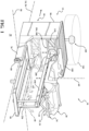
- an example of system 10 includes a transport device 14 shown engaged with a carrier 15.
- carrier 15 is a first build device 16 in the form of a first fixture 18.
- first fixture 18 is supporting a workpiece or article 20, for example the sheet metal underbody frame for a passenger vehicle.
- workpieces or articles 20 may be engaged, supported and transferred by transport device 14 and system 10.
- workpieces or articles 20 may include single components, multiple separate components, partially completed subassemblies, or completed products.
- the workpieces 20 may be other objects and/take other forms as known by those skilled in the art.
- system 10 and transport device 14 includes a predetermined path of travel 24.
- exemplary transfer device 14 is an autonomous, or semi-autonomous, device and/or a form of an automated guided vehicle (AGV) wherein, in one example, preprogrammed instructions as to a route or path of travel 24 are stored and executed by a control system onboard the transfer device 14.
- AGV automated guided vehicle
- transport device may not include a predetermined or prestored in memory path to travel.
- transport device may wirelessly receive data signals or instructions "on-the-fly" which direct the direction of movement, rate of travel, or other operations of device 14.
- transport device 14 when the transport device 14 is positioned in a workstation 30, transport device 14 is operable to reciprocally move the first build device 16 and workpiece 20 from a first position 34 well above the floor to a lower second position 40 (shown schematically in FIG. 1 as a lower zone or volume of space) along a Z axis 60 or coordinate direction.
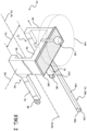
- the second position 40 provides for the automatic placement or deposit of the workpiece 20 on a second build device 46, shown in the exemplary form of a second fixture 48 (shown schematically as rectangle volumes in FIG. 1 and an exemplary holding fixture 48 in FIG. 3 ).
- the exemplary second fixture 48 precisely and accurately positions the workpiece 20 in the workstation 30 in the X axis or coordinate direction 24/56, the Y axis or coordinate direction 58, and the Z axis or coordinate direction 60 as generally shown for precision assembly or manufacturing operations on the workpiece 20.
- Second build device 46 is shown supported by an exemplary stationary platform 50 rigidly connected to the assembly plant floor. It is understood that first build device 16, second build device 46 and platform 50 can take any structures forms or orientations to suit the particular application of system 10 and industrial environment.
- exemplary transport device 14 includes a frame 66 having a pair of rails 70 and sidewalls 90 as generally shown.
- Transport device 14 further includes a cross-member 96 connected to the top portions of the side walls 90.
- the frame 66 and cross-member 96 define a clearance opening or through passage 72 through the frame 66 along the X axis 56 having a clearance opening width 76 and a clearance opening height 78.
- Exemplary transport device 14 further includes a pair of casters 80 and drive wheels 84 (shown in FIGS. 4 and 5 ) allowing transport device 14 to roll along the path of travel 24.
- cross-member 96 is box-shaped having an internal cavity (not shown) having a top 100 to package and securely house the control system and/or possibly other materials described below.
- the exemplary rails 70, side walls 90, cross-member 96, and top 100 are preferably made from strong, rigid, load bearing materials such as steel or aluminum. Lighter materials, for example carbon fiber composite materials, may be used to suit the particular application and industrial environment. It is understood that frame 66, rails 70 and cross-member 96 may take other forms, shapes, configurations, sizes, and materials to suit the particular application and performance requirements as known by those skilled in the art.
- exemplary transport device 14 further includes a manipulator device 104.
- Manipulator device 104 is operable to move a carrier 15 relative to the frame 66 and workstation 30.
- manipulator device 104 may take the form of a lift device 108 which is operable to selectively move the carrier 15, for example the first build device 16, from the first position 34 to the second position 40.
- the manipulator rotates a mounting plate or support member relative to the frame.
- Other examples of movement of the carrier and/or workpiece relative to the frame 66 or workstation known by those skilled in the art may be used.
- lift device 108 includes a rigid support frame 110.
- support frame 110 is positioned in the opening 72 and extends across opening width 76 ending with guide plates 116 as generally shown and best seen in FIG. 5 .
- a mounting plate 130 is connected to the support frame 110.
- Exemplary mounting plate 130 is used to provide a connection or anchor point for the carrier 15, for example a support device 186 to support frame 110, discussed further below.
- mounting plate 130 is rigidly connected to support frame 110.
- mounting plate 130 may rotate relative to support frame 110 about an axis of rotation 134.
- mounting plate 130 may move relative to support frame 110 in other ways, for example, linearly along the X axis 56, Y axis 58 and Z axis 60 directions.
- manipulator device 104 in the form of lift device 108 includes a powered drive system (not shown) including a track 120 extending along the Z axis 60 on an inner surface of both frame side walls 90 between the first position 34 and the second position 40.
- a powered drive system (not shown) including a track 120 extending along the Z axis 60 on an inner surface of both frame side walls 90 between the first position 34 and the second position 40.
- Each exemplary guide plate 116 is engaged with a respective track 120 which are in communication with a drive device, for example an electric motor or hydraulic motor and cylinder, to selectively move the support frame 110 along track 120 between the first position 34 and the second position 40.
- the drive device may be positioned in the cross member 96.
- the drive device (not shown) and track may take many forms, for example toothed gears engaging a rack positioned along the track 120, a chain engaged by driven sprockets, toothed belts, cogged pulleys and/or other drive devices known by those skilled in the art.
- the manipulator device 104 is powered by one or more batteries (not shown) positioned in the cross-member 96 cavity and in electric communication with the manipulator device 104, drive wheels 84, control system 150 and/or other onboard devices requiring electric power.
- batteries not shown
- Other sources of electricity or power for example induction motors, known by those skilled in the art may be used.
- exemplary system 10 and transport device 14 includes one or more sensors 140 having a field of vision 146 to assist in the navigation and/or object detection for transport device 14 to move along the path of travel 24.
- sensor 140 is a omni-directional 360 scanner, for example a laser scanner or LIDAR (light imaging, detection and ranging) system, which actively scans, monitors and measures distances between the transport device 14 and distant objects.
- LIDAR light imaging, detection and ranging
- additional sensors 140A and 140B having respective fields of vision 146A and 146B may be used on other locations of the frame 66, cross-member 96 or other areas of transport device 14 to suit the particular application and performance requirements of system 10.
- interior sensors for example on the inside walls 90 in the clearance opening 72, may be used to detect platform 50 and second build device 46 to guide and position transport device 14 relative to platform 50 and second build device 46.
- system 10 and transport device 14 is an autonomous or semi-autonomous device capable of self-driving movement and navigation based on use of one or more of the above sensors in communication with the control system 150 and drive wheels 84.
- sensors for example proximity sensors, ultrasonic sensors, global positioning satellite (GPS), or local triangular positioning devices, may be used to assist and/or control the navigation of transport device 14 known by those skilled in the art.
- GPS global positioning satellite
- local triangular positioning devices may be used to assist and/or control the navigation of transport device 14 known by those skilled in the art.
- ATC automated guided carts
- other devices for example wires or paint on the floor readable by a sensor, may be used as known by those skilled in the art.
- transport device 14 includes a control system 150 useful to monitor, navigate the movement and/or location of transport device 14 along the path of travel 24 as well as actuate and control movement of the drive wheels 84 and the lift device 108.
- Exemplary control system includes a microprocessor 152 and a data memory storage device 154.
- Exemplary microprocessor or central processing unit (CPU) 152 is a conventional or specialized computer processor including an on operating system.
- the CPU 152 is operable to receive data, for example to send and receive data or instructions from the memory storage device, processes the data according to preprogrammed or stored instructions in its memory and provide outputs.
- the electronic data or information memory storage device 154 may include one or more of common data/information storage devices to, temporarily and/or permanently, store operating instructions, software and executable instructions to the processor 152 and/or controllers and actuators 156 to send and receive signals to and from the various drive or executable devices discussed above.
- Control system 150 may further include one or more conventional or specialized controllers and actuators 156 for controlling and/or monitoring various devices in system 10 or transfer device 14.
- One or more of the hardware and software components may be a part of a larger programmable logic controller (PLC).
- Exemplary control system 150 further includes a transmitter and receiver 158 for sending and receiving wireless signals and data between the control system 150 and other devices, for example a local or remote server 174.
- control system 150 is in communication and sends and receives data signals from a local server as part of a broader control system.
- PLC programmable logic controller
- the industrial facility or plant may include a communication network which may include local area network (LAN) including, for example, one or more wireless routers for communication based on an IEEE standard 802.11 (also known as Wi-Fi), or known hardware for communication based on IEEE 802.03 (also known as Ethernet).
- LAN local area network
- IEEE standard 802.11 also known as Wi-Fi
- IEEE 802.03 also known as Ethernet
- Other known communication protocols for example BLUETOOTH suitable for an industrial environment may be used as known by those skilled in the art.
- These networks may be in communication with a cloud communication network, for example the internet, virtual private network, a private network, a point-to-point network or any other suitable network, or combinations of networks, known by those skilled in the art.
- Exemplary control system 150 includes one or more buses 170 which allow communication between the various components described above in control system 150.
- the transport device 14 drive wheels 84, lift device 108 and sensors 140, 140A and 140B are in communication with the control system 150 to activate, deactivate, monitor and/or control the operation of the actuators, motors and other devices based on execution of instructions, pre-programmed onboard the device 14, or as received through communication of remote instructional devices, for example remote servers 174.
- these devices may be powered by a power source, for example rechargeable batteries or battery packs stored in the cross-member 96. Additional hardware and software devices and programs may be used in the control system 150 as known by those skilled in the art depending on the application and performance requirements of system 10.
- support device 186 is useful to engage and support a first build device 16 as generally shown and described below.
- support device 186 includes an elongate, rigid support bar 190 having a first end 194 that rigidly or removably connects to the mounting plate 130 through a gusset or mounting bracket 200 as best seen in FIG. 1 .
- the exemplary support bar 190 is made from steel, aluminum or other materials suitable for the particular application.
- carrier 15, support device 186, support bar 190 and first build device 16 can be an integral, single component or a single device formed from one or more of the mentioned structures.
- the carrier 15 and/or support device 186 may take forms, shapes, sizes, orientations, numbers and constructions other than elongate support bar 190 as illustrated.
- support bar 190 may be configured to be a "U" or "V" shape providing a platform or support surface for a container or other carrying device, for example, loose components or raw materials, as discussed further below.
- the exemplary carrier 15 in the form of a support bar 190 may further be in the form of an elongate, rigid bar including a second end 206 and one or more connectors 210 which provide a connection or anchor point for the first build device 16 further described below.
- the connectors 210 can take many forms which provide a secure mechanical attachment between the support bar 190 and the first build device 16.
- the connectors 210 can alternately provide a permanent, removable or quick-release type connection to engage first build device 16.
- Mechanical bolts, mounting studs or locking pins are examples of a removable connector 210.
- Other forms for connector 210 may be used as known by those skilled in the field. In one example best seen in FIG.
- a guide 236 is used to assist in the positioning of the support device 186, for example elongate support bar 190, along the Y direction 58.
- Exemplary guide 236 may include two rigid bars connected to platform 50 extending upward along the Z axis 60 defining a vertical slot to receive and guide bar 190 as the lift device 108 moves between the first position 34 and the second position 40. Rollers or other devices (not shown) may be included to further guide and/or reduce friction and/or wear between the abutting components.
- Other guide and positioning assist devices, positioned on platform 50 or support device 186, may be used to suit the particular application.
- transport device 14 includes the carrier 15 connected to the manipulator device 104.
- carrier 15 is a first build device 16 further described below.
- carrier 15 can take the form of a container.
- the container may be a rigid holding crate or other shipping or transport container useful to temporarily store loose components described above to be transported by transport device 14 from one location to another.
- the container is a rigid, rectangular shipping crate having an open top allowing easy loading and unloading of loose components identified above.
- standard industrial assembly plant shipping crates can be quickly connected to support device 186, for example by a robot or forklift, so transport device can transport the materials to a desired location, for example, from an assembly plant warehouse area to an active assembly line for use in assembly operations.
- the carrier or support device 186 is in a "U" or "V" configuration
- the shipping crate can be placed atop of the carrier 15 or mechanically secured through connection devices 210 described above.
- the support device 186 can be integral with carrier 15.
- the carrier 15 may be easily connected to the storage crates which are then easily connected to the device 14 mounting plate 130.
- Other carriers 15 having different sizes, shapes, orientations, connection schemes known by those skilled in the art may be used.
- carrier 15 is, or includes, a first build device 16 in the form of a first fixture 18.
- First fixture 18 is shown engaged with the support bar 190 through connectors 210 in a manner described above.
- Exemplary first fixture 18 is a subassembly holding fixture including base 212 in the form of an elongate rigid rod or bar. It is understood that base 212 can be integral with bar 190 (a single bar 190 also serves as base 212).
- First fixture 18 further includes a plurality of arms 218 connected to the base and part supports 224 connected to the arms 218.
- part supports 224 can take many forms and orientations such as a horizontal support surfaces, hooks, power-actuated clamps in communication with control system 150, or other static or actuated devices needed for support and/or secure engagement with the respective portion of workpiece 20.
- Arms 218 and part supports 224 are made from steel, aluminum or other materials suitable for the application. The number, location, size, configuration and orientation of first fixture 18, first fixture arms 218 and 224 will vary depending on the workpiece 20 the support device 186 is designed to accommodate.
- first build device 16 can take the form of other holding fixtures for transporting individual components or articles by transport device 14.
- first build device 16 can include a flat or multi-level sheet of steel or aluminum with precision-positioned holes (for example a grid pattern having precision aligned holes 100 mm apart) and individual brackets or tooling for positioning individual assembly components, subassemblies, tooling and/or equipment relative to the steel sheet.
- the precisely positioned components can be removed from the first build device 16 by a robot or other manipulator to support assembly operations at the workstation or other processes.
- Other holding fixtures, welding fixtures, component assembly or positioning devices, tooling, equipment end effectors, equipment maintenance devices, for example weld tip dressing tools, and/or tooling can serve as the first build device 16 or the second build device 46 to suit the particular application.
- first build device 16 or the second build device 46 examples include devices that can be included or supported on the first build device 16 or the second build device 46 .
- the transport device is used in an assembly line equipment maintenance capacity, replacement end effectors, weld gun tip dressers, processing testing equipment, for example weld gun test coupons, may be positioned on carrier 15 or first fixture 18.
- process evaluation or maintenance equipment maybe be mounted to carrier 15 or first build device 16.
- cameras or other imaging devices may be mounted to carrier 15 and transported to a desired location and workstation to image or otherwise record a process cycle to ensure the process is conducted according to design specifications.
- Other carriers 15, first build devices 16 and first fixtures 18 may be used to suit the particular application and as known by those skilled in the art.
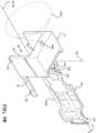
- carrier 15 in the form of a first build device 16 includes an alternate first fixture 18A used to vertically suspend workpiece 20 below the first build device 16 along the Z axis 60 as generally shown.
- Alternate first fixture 18A includes alternate arms and part supports than as generally described for FIG. 7 above.
- the work supports 224 may include powered actuated clamps, hooks or other articulatable engagement devices in connection with control system 150. Once workpiece 20 is engaged with the second build device 46, the work supports 224 would be actuated to release engagement with workpiece 20.
- the parts supports 224 may continue engagement with the workpiece, but allow flexibility of movement so the workpiece can fully engage second build device 46 for accurate and precise positioning and orientation of workpiece 20 in the X, Y and Z axis directions on the second build device 46 for predetermined processing at the workstation 30.
- one or more sensors may be used to determine the location of the carrier 15, or of the arms and/or part supports, to monitor the respective positions of the carrier, respective arms, part supports or the workpiece.
- the part support actuators could be actuated (or opened) allowing disengagement of the workpiece 20 from the first fixture 18, 18A allowing the lift device 108 to raise or otherwise move the first fixture 18, 18A out of the way so predetermined processing can take place on the workpiece, for example by programmable robots disclosed below.
- Exemplary sensors may include cameras or other optical imaging devices. Other sensors known by those skilled in the art may be used.
- alternate transport system 10A which does not form part of the invention, is illustrated.
- the transport device 14A is similar to that described above, but with an alternate manipulator device 104A and no use of a second build device 46.
- alternate manipulator device 104A provides for rotation of mounting plate 130 about an axis of rotation 134 to selectively reorient carrier 15 in the form of the first build device 16 and workpiece 20 relative to the frame 66 and/or workstation 30.
- One exemplary application is to reciprocally rotate workpiece 20 in the workstation 30 to provide additional access or clearance to inspect the workpiece 20 by an operator as generally shown.
- Alternate manipulator device 108A may also include lift device 108 to reciprocate between the first position 34 and the second position 40 along the Z axis 60 as previously described for lift device 108.
- mounting plate 130 (and carrier 15) is operable to rotate relative to support frame 110.
- mounting plate 130 includes structures, for example planetary gears or journal bearings to engage carrier 15, for example support device 186, thereby allowing support device 186 to rotate relative to mounting plate 130.
- a drive motor (not shown) is in communication with the control system 150 and is engaged with the rotating component to ultimately rotate carrier 15 as generally shown.
- Other structures, components and devices for rotating carrier 15, for example first build device 16, known by those skilled in the art may be used.
- transport device 14 is preprogrammed, or otherwise receives data signal instructions in real time through wireless communication in one of the forms described above, to move along the predetermined path of travel 24, 56.
- transport device 14 is logistically monitored and/or navigated through use of sensors 140, 140A, and 140B in communication with control system 150.
- transport device 14 may not be preprogrammed with onboard instructions in the control system 150 with a predetermined path of travel.
- the transport device 14 may receive wireless data signal instructions in real time (or close thereto) from a local or central plant control system to guide the transport device 14 along a desired path of travel.
- the transport device 14 course or path of travel can be altered "on-the-fly" by receipt of data signal instructions which change or alter the path of travel from a prior destination to an alternate destination to pick-up or transport materials to better support plant or assembly operations.
- first build device 16 and workpiece 20 are located at the first position 34.
- the second build device 46 is positioned along the path of travel 24, and is sized and oriented, to pass through transport device clearance opening 72 as the frame 66 continues to move along the path of travel 24.
- sensors 140, 140A, 140B, other sensors (not shown), or other position locating system for example a closed-loop feedback system incorporated in control system 150 and/or an industrial plant central control center, the transport device 14 stops movement along the path of travel 24 positioning first build device 16 in the position shown in FIGS. 3 and 4 , positioned above second build device 46.
- the lift device 108 is actuated by control system 150 to lower support frame 110 along the Z axis 60 from the first position 34 to the predetermined second position 40 as best seen in FIG. 3 .
- the first build device 16 and the second build device 46 are configured such that on movement of the first build fixture 16 between the first position 34 and the second position 40, there is clearance defined by the second build device 46 such that there is no physical contact or interference between the first build device 16 and the second build device 46.
- the second build device on moving transition of the first build device 16 between the first position 34 and the second position 40, engages the workpiece 20 (shown in dashed line in FIG 3 ) which simultaneously disengages the workpiece 20 from the first fixture 18.
- precision locating pins 230 are located on the arms or part supports of the second fixture 48 which engage precision located holes in the workpiece 20.
- Other mechanical devices other than locating pins 230 may be used to engage and position workpiece 20 relative to the second build device 46 as known by those skilled in the field.
- the first fixture 18 would continue to lower in the Z direction 60 after disengagement to, for example, provide additional clearance or avoid interference with the workstation operations.
- second build device 46 is positioned in the workstation 30 in a known, accurate and precise location in the X coordinate or axis 56, the Y coordinate or axis 58, and the Z coordinate or axis 60 relative to the workstation 30 and process equipment positioned therein.
- second build device 46 can position workpiece 20 within +/- 0.15 millimeters (mm) from a target or predetermined design position. Other dimensional variations from a target position may be used or achieved depending on the form or configuration of system 10 and transport device 14. It is understood that second build device 46 and second fixture 48 can take other forms, shapes, sizes (within the size of the clearance opening 72), orientations and structures to suit the particular application.
- the construction and configuration of the exemplary second build device 46 and second fixture 48 for example arms and part supports, which engage and support workpiece 20 to position and orient workpiece 20 in a known, accurate and precise location in the X coordinate or axis 56, the Y coordinate or axis 58, and the Z coordinate or axis 60 relative to the workstation 30, may vary.
- the control system 150 actuates, for example electric motors described above, and begins to raise the lift device 108 to re-engage the first build device 16 (for example first fixture 18) and disengage the workpiece 20 from the second build device 46 to reposition the lift device and workpiece 20 at the first position 34.
- control system 150 actuates the drive wheels 84 to continue movement of the transfer device 14 along the path of travel 24 to the next predetermined workstation 30 or other destination.
- path of travel 24 has been described as along an X axis, it is understood that the system 10 and device 14 path of travel can take forms other than a linear path.
- transport device 14 in the form of an AGV an almost unlimited number of paths of travel 14 can be predetermined, or self-navigated by device 14, or guided by real-time wireless instructions, by the transport device 14 through use of sensors 140, 140A, 140B and other sensors and navigating devices and systems described above.
- a substantial portion of the path of travel 24 may be linear, for example along a long, continuous assembly line.
- path of travel 24 can have curved portions, for example moving from one linear assembly line to another, or for example, from an assembly line to another area of the assembly facility.
- the transfer device 14 can be instructed/directed through receipt of data signals described above to alter its prior programmed (or non-programmed) path of travel and move to an inspection area adjacent to, or remote from, the assembly line path of travel 24.
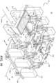
- exemplary transport system 10 is shown in use with exemplary process equipment at a workstation 30.
- a transport device 14 including a first build device 16 is used with a second build device 46 generally described above.
- second build device 46 (for example second fixture 48) is positioned on an alternate platform 50A which is movable in the X direction 56 and the Y direction 58 through use of an independent AGV 280.
- AGV 280 and platform 50A may also move the second build device in the Z axis 60 direction to suit the particular application. It is understood that second build device 46 can be positioned and secured to a stationary platform 50 as previously described.
- exemplary AGV 280 may selectively engage platform 50A and move the platform 50A and connected second build device 46 to a selected position along the path of travel 24 or other location in the workstation 30.
- Connection or engagement mechanisms between the AGV and the platform 50 may include engagement pins that are actuated to rise and engage coordinated holes or areas of the platform 50 to raise and lower the platform 50 relative to the AGV 280 to position and move platform 50A as needed.
- Other engagement devices between the AGV 280 and the platform 50A may be used to suit the particular application as known by those skilled in the art.
- a plurality of second build devices 46 and platforms 50A can be built and configured so selected second build devices 46 are specific to or designed for a workpiece, product or article A, and some built and configured for a different workpiece, product or article B.
- the AGV 280 can be preprogrammed or wirelessly instructed to engage, maneuver, insert and position the proper second build device 46 into the path of travel to accommodate the predetermined industrial plant build sequence of workpieces, products or articles, for example, different vehicle body styles, to meet varying production demand.
- system 10 and transport devices 14 can be selectively transferred to locations or workstations where the appropriate second build device 46 is positioned to coordinate with the workpiece 20 carried by the transport device 14. This provides significant flexibility to assembly process facilities and is efficient in the floor space and configuration of the industrial facility.
- system 10 and workstation 30 includes two sets of platforms 260 supporting programmable robots 266 and associated robot controls cabinets 276 (three robots 266 and control cabinets 276 shown on each platform 260 for each side of the path of travel 24).
- the platforms 260 are selectively engageable and positioned adjacent the system 10 path of travel in a workstation 30 through use of independent AGV's 280A as previously described for AGV 280.
- platforms 260 may move perpendicular to the path of travel direction 24, 56 along Y axis 58 or parallel to the path of travel direction 24, 56.
- different process equipment for example alternately programmed robots 266 or other assembly or manufacturing process equipment can be autonomously, or semi-autonomously, moved into the workstation 30 and adjacent to the path of travel 24 by the AGV's 280A for predetermined process engagement with workpiece 20 positioned on the first build device 16 or the second build device 46.
- one set of robots may conduct processes on workpiece 20 while the workpiece 20 is engaged with the first build device 16 at the first position 34 (shown in FIG. 11 ).
- the workpiece 20 can be lowered or reoriented by transport device 14 lift 108 to the second build device in the manner described above for additional operations on workpiece 20 by alternate robots or equipment.
- platforms 260, robots 266 and control cabinets may be modular, self-contained systems wherein the platform or pallet 260 and installed process equipment is prebuilt, pre-tested or validated away from the assembly line and delivered to the plant facility.
- the modular platform is then delivered to the workstation, connected to a power source and placed in communication with the control system (by hardwire or wireless) and rendered production ready with little or no downtime of the assembly process.
- One example of the described modular application equipment pallets or modular assembly tool devices are described in United States Patent Application Publication Number 2016/0167724 assigned to the present assignee.
- safety fencing may be positioned perpendicular to the assembly line on either side of the workstation 30 (extending outwardly along the Y coordinate direction 58). Further, a portion of safety fencing (not shown) may be connected to the platform 260 extending along the outboard side parallel to the path of travel direction 24, 56. On moving of the platform 260 into the workstation 30 and adjacent to the path of travel 24, the perpendicular-positioned fencing and the fencing connected to the platform 260 form a three-sided safety fence structure to prevent unauthorized access to the robots 266 and control cabinets 276. Other safety fencing or safety structures may be used to suit the particular application.
- other safety devices for example sensors may be installed to the platforms 260 to detect unauthorized objects within a certain area of workstation.
- the control system 150 or control system of the robots 266 may stop movement and production process until the detected object is no longer detected or a signal is received that it is safe to recommence operations in the workstation 30.
- the platforms 260 and robots 266 can be permanently or semi-permanently stationed or secured in a particular workstation 30 so as to conduct the same or similar processes on predetermined workpieces 20 that the system 10 transfers into as described in the above examples. It is understood that other process equipment other than programmable, multi-axis robots 266 and platforms 280A may be used with, or included in, system 10.
- an alternate application of transport system 10 is illustrated.
- the process equipment for example programmable process robots 266, are positioned on overhead structures rather than at ground level through platforms 260 as described for FIGS. 10 and 11 .
- an overhead, rigid scaffold-type frame structure 284 may be used to support inverted robots (schematically shown as 266A) to conduct work on the workpieces transferred through workstation 30 by system 10 and devices 14 as described above.
- inverted robots (schematically shown as 266A) to conduct work on the workpieces transferred through workstation 30 by system 10 and devices 14 as described above.
- An overhead scaffold or support structure is described in US Patent No. 8,201,723 assigned to the assignee of the present invention and incorporated herein by reference.
- Other infrastructure or devices for supporting robots or other assembly or manufacturing equipment may be used to suit the particular application.
- FIGS. 13A - 13C an exemplary use of system 10 along path of travel 24 is illustrated.
- two different sets of tools or second fixtures 48 are used to service a single workstation 30 (two workstations 30 shown).
- Each workstation 30 is equipped with a second fixture 48 in the form of tool A 48A and a second fixture 48 in the form of a tool B 48B.
- the second fixture tool A 48A and second fixture tool B 48B are supported by platforms 50A (not shown in FIGS. 13 , but see FIG.
- Second fixtures 48 tool 48A and 48B maybe be moved into and out of the workstation 30 by a respective AGV 280 previously described and illustrated in FIG. 11 .
- Other powered devices may be used to move the second fixture tools 48A and 48B into and out of the workstation 30.
- a powered roller or belt drive system or shuttle (not shown) engaged with a respective tool A or B, as known by those skilled in the field.
- the workstations 30 each have received a second fixture tool A 48A adjacent to the robot platforms 260 (each tool A 48A moved from right to left in FIG, 13A ).
- Second fixture tool A 48A's may be moved to the workstation 30 based on a predetermined work or production schedule sequence, or other predetermined metric.
- the instructions or signals to monitor, initiate and control movement of the second fixtures 48 tools 48A and 48B may be coordinated and executed by a local communication system, for example in each workstation 30 control system (not shown), locally per an assembly line, or remotely through a plant facility central control system (see central server 174 in FIG. 6 ).
- Sensors may be used along with the control system to monitor the movement and position of the second fixtures 48 as they move into and out of respective workstations 30.
- One example of an industrial communication system and method for monitoring and controlling movement of the transfer devices 14 and device for reciprocally moving second fixture tools 48A and 48B is described in US Patent Application Publication 2010/0241260 .
- FIG. 13B an alternate example of second fixture 48 tools 48B are moved to the respective workstation 30 (tools 48 B moving from left to right from the position shown in FIG. 13A ) following movement of tools 48A out of the workstation 30 (tools 48A moving from left to right from the position shown in FIG. 13A ).
- One example for changing the second fixtures 48 from tool A to tool B include changing of assembly production from a vehicle model A to a vehicle model B.
- the platforms 260 and associated robots 266 may also change and move into and out of workstation 30 to accommodate which workpiece 20 is entering the workstation 30. Coordination, activation and execution of the equipment in workstation 30 at a particular time can be instructed, monitored and controlled by local or remote control systems as described above.
- one workstation 30 includes second fixture tool A 48A (workstation to the left in FIG. 13C ) and one workstation 30 includes second fixture tool B 48B (workstation to the right in FIG. 13C ).
- second fixture tool A 48A workstation to the left in FIG. 13C
- second fixture tool B 48B workstation to the right in FIG. 13C
- Other combinations, and/or alternate or additional second fixture tools 48 may be used to suit the particular application.
- transport device 14B positioned between the two sequential workstations 30.
- transport device 14B is preferably not being processed by robots 266 or other devices, but is waiting in line or queue to travel into the next workstation 30 (to the left as shown in FIG. 13A ).
- This extra or waiting transport device 14B may provide for inspection, or sub-processing operations, or be eliminated, depending on the application.
- a transport device for example 14
- a first build device for example first build device 16 and first fixture 18
- a path of travel for example 24
- the transport device 14 is stopped at a workstation 30.
- positioning and stopping of transport device 14 at a predetermined position in the workstation 30 is monitored and executed by control system 150.
- the transport device 14 causes the first build device 16 and workpiece 20 to move relative to the workstation 30, for example lowering in the Z axis 60 or rotating the workpiece about a rotational axis 134 by lift 108 as described above.
- a method step 405 is required where a second build device 46 is positioned along the path of travel 24, on moving the transport device 14 into the workstation 30, the second build device 46 passes through clearance opening 72 in the transport device 14 as described above.
- moving the workpiece 20 relative to the workstation includes the additional step(s) of moving the first build device 16 and workpiece 20 from the first position 34 to the second position 40, thereby depositing the workpiece 20 into the second build device 46 and disengaging the workpiece 20 from the first build device 16 as described above.
- additional method steps include conducting processing on the workpiece 20 and returning the first build device 16 to the first position 34 thereby re-engaging workpiece 20 as described above prior to the control system reactivating the drive wheels 84 to recommence movement of transport device 14 along the path of travel 24 to the next predetermined workstation 30 or other destination.
Landscapes
- Engineering & Computer Science (AREA)
- Transportation (AREA)
- Mechanical Engineering (AREA)
- Structural Engineering (AREA)
- Manufacturing & Machinery (AREA)
- Chemical & Material Sciences (AREA)
- Combustion & Propulsion (AREA)
- Civil Engineering (AREA)
- Life Sciences & Earth Sciences (AREA)
- Geology (AREA)
- Automatic Assembly (AREA)
- Automobile Manufacture Line, Endless Track Vehicle, Trailer (AREA)
- Refuse Collection And Transfer (AREA)
- Supplying Of Containers To The Packaging Station (AREA)
Applications Claiming Priority (2)
| Application Number | Priority Date | Filing Date | Title |
|---|---|---|---|
| US201762582379P | 2017-11-07 | 2017-11-07 | |
| PCT/US2018/059454 WO2019094385A1 (en) | 2017-11-07 | 2018-11-06 | Transport system and methods |
Publications (2)
| Publication Number | Publication Date |
|---|---|
| EP3707096A1 EP3707096A1 (en) | 2020-09-16 |
| EP3707096B1 true EP3707096B1 (en) | 2024-06-12 |
Family
ID=64362774
Family Applications (1)
| Application Number | Title | Priority Date | Filing Date |
|---|---|---|---|
| EP18804902.7A Active EP3707096B1 (en) | 2017-11-07 | 2018-11-06 | Transport system and methods |
Country Status (7)
| Country | Link |
|---|---|
| US (1) | US10640297B2 (pl) |
| EP (1) | EP3707096B1 (pl) |
| CA (1) | CA3080393C (pl) |
| ES (1) | ES2981127T3 (pl) |
| MX (2) | MX2020004708A (pl) |
| PL (1) | PL3707096T3 (pl) |
| WO (1) | WO2019094385A1 (pl) |
Families Citing this family (23)
| Publication number | Priority date | Publication date | Assignee | Title |
|---|---|---|---|---|
| FR3034410B1 (fr) * | 2015-04-02 | 2020-10-23 | Gebo Packaging Solutions France | Dispositif de convoyage par chariot autonome |
| US10867823B2 (en) * | 2018-05-29 | 2020-12-15 | Taiwan Semiconductor Manufacturing Co., Ltd. | Fault detection method in semiconductor fabrication |
| JP7035860B2 (ja) * | 2018-07-04 | 2022-03-15 | トヨタ自動車株式会社 | 自動車の製造方法 |
| JP2020035385A (ja) * | 2018-08-31 | 2020-03-05 | 三菱重工業株式会社 | スケジュール作成装置、スケジュール作成方法及びプログラム |
| DK3620357T3 (da) | 2018-09-05 | 2021-06-07 | Comau Spa | Autonomt køretøj, såsom et automatiseret ført køretøj eller en autonom mobil robot |
| SG11202111287RA (en) | 2019-04-25 | 2021-11-29 | Aero Vironment Inc | Off-center parachute flight termination system (fts) |
| AU2020315515B2 (en) | 2019-04-25 | 2025-12-04 | Aerovironment, Inc. | Method of operating a high altitude long endurance aircraft for maximizing solar capture |
| EP3959140B1 (en) * | 2019-04-25 | 2026-01-07 | AeroVironment, Inc. | Ground support equipment for a high altitude long endurance aircraft |
| JP7472169B2 (ja) | 2019-04-25 | 2024-04-22 | エアロバイロメント,インコーポレイテッド | 高高度長航続時間航空機の上昇及び滑空動作の方法 |
| AU2020307360B2 (en) | 2019-04-25 | 2025-09-25 | Aerovironment, Inc. | Method of flight plan optimization of a high altitude long endurance aircraft |
| DE102019117036A1 (de) * | 2019-06-25 | 2020-12-31 | Eisenmann Se | Freifahrender Transportwagen und Fördersystem zum Fördern sowie Behandlungsanlage zum Behandeln von Werkstücken |
| DE102019130619A1 (de) * | 2019-11-13 | 2021-05-20 | Bayerische Motoren Werke Aktiengesellschaft | Fahrzeugkarosseriefördereinrichtung |
| US11460862B2 (en) * | 2020-02-03 | 2022-10-04 | Ford Global Technologies, Llc | Deployable mobile transporters for easy plant reconfiguration |
| US20230047883A1 (en) * | 2020-02-04 | 2023-02-16 | Magna Exteriors Inc. | Flexible punch and weld system |
| US12077380B2 (en) * | 2020-04-06 | 2024-09-03 | Sailrail Automated Systems, Inc. | Cart loader/unloader and a switcher system and improvements therein |
| US11655100B2 (en) * | 2020-04-06 | 2023-05-23 | Sailrail Automated Systems, Inc. | Cart loader/unloader and a switcher system |
| JP7608094B2 (ja) * | 2020-09-11 | 2025-01-06 | 株式会社東芝 | 移動体、制御装置、監視装置、制御方法、及びプログラム |
| US20230196217A1 (en) * | 2021-12-22 | 2023-06-22 | Ford Global Technologies, Llc | Systems and methods for controlling pallets in a manufacturing environment using reinforcement learning |
| CN116829442A (zh) * | 2022-01-27 | 2023-09-29 | 宁德时代新能源科技股份有限公司 | 车辆总装生产线和车辆总装的方法 |
| DE102022113665B3 (de) | 2022-05-31 | 2023-07-06 | Dr. Ing. H.C. F. Porsche Aktiengesellschaft | Fahrzeugkarosseriefördereinrichtung |
| CN115446795A (zh) * | 2022-08-31 | 2022-12-09 | 河南平原智能装备股份有限公司 | 一种能够调节角度的车架纵梁取放件装置 |
| DE102024109349A1 (de) * | 2024-04-03 | 2025-10-09 | Fixture Tech Solutions Gmbh | Bausatz für den Zusammenbau eines Systems zum Transport von Fahrzeugteilen zu einer Messstation und zum Halten der Fahrzeugteile |
| DE102024109345A1 (de) * | 2024-04-03 | 2025-10-09 | Fixture Tech Solutions Gmbh | System zum Transportieren von Fahrzeugteilen, insbesondere eines Fahrzeugchassis |
Family Cites Families (119)
| Publication number | Priority date | Publication date | Assignee | Title |
|---|---|---|---|---|
| US3854889A (en) | 1954-07-28 | 1974-12-17 | Molins Organisation Ltd | Automatic production machinery |
| US4369563A (en) | 1965-09-13 | 1983-01-25 | Molins Limited | Automated machine tool installation with storage means |
| US4032018A (en) | 1975-11-21 | 1977-06-28 | Wallis Bernard J | Workpiece transfer mechanism |
| US4328422A (en) | 1978-03-27 | 1982-05-04 | Litton Systems, Inc. | Automated warehouse vehicle position determining system |
| US4232370A (en) | 1978-12-07 | 1980-11-04 | Clark Equipment Company | Control system for a storage/retrieval machine in an automated material handling system |
| US4404505A (en) | 1981-03-03 | 1983-09-13 | Swanson Systems, Inc. | Programmable multiple position machine |
| US4442335A (en) | 1982-03-31 | 1984-04-10 | Comau S.P.A. | Side aperture welding assembly system |
| IT1152517B (it) | 1982-09-02 | 1987-01-07 | Rosa Gaetano Di | Impianto automatico per assemblaggio e saldatura di scocche di autoveicoli |
| US4530056A (en) | 1982-10-28 | 1985-07-16 | Modular Automation Corp. | Automated guided vehicle system |
| FR2557844B1 (fr) | 1984-01-11 | 1986-05-30 | Sciaky Sa | Installation pour l'assemblage et, notamment, l'epinglage de carrosseries de vehicules automobiles |
| IT1173481B (it) | 1984-03-26 | 1987-06-24 | Rosa Gaetano Di | Impianto automatico per l'assemblaggio e saldatura di scocche di autoveicoli,dotato di un ritmo produttivo altissimo,mantenibili anche in concomitanza del cambio del modello in linea e quindi del cambio dei conformatori |
| JPS6112474A (ja) | 1984-06-26 | 1986-01-20 | Toyota Motor Corp | 車体組立装置 |
| DE3443076A1 (de) | 1984-11-26 | 1986-06-05 | Kuka Schweissanlagen + Roboter Gmbh, 8900 Augsburg | Flexibles fertigungssystem fuer die bearbeitung und herstellung mehrteiliger baugruppen, insbesondere rohkarosserie-baugruppen |
| US4657463A (en) | 1985-02-19 | 1987-04-14 | Eaton-Kenway, Inc. | Automated guided vehicle |
| IT1184631B (it) | 1985-06-21 | 1987-10-28 | Fata Europ Group | Impianto per il montaggio automatico di una porta o di un analogo componente di chiusura entro il relativo vano ricavato in una scocca,in particolare di un autoveicolo |
| US4734979A (en) | 1985-12-25 | 1988-04-05 | Mazda Motor Corporation | Weighty object mounting systems |
| US4679297A (en) | 1986-05-15 | 1987-07-14 | Gmf Robotics Corporation | Method for changing the tooling in a robot-based system and system utilizing same |
| JPH07115663B2 (ja) | 1986-09-01 | 1995-12-13 | トヨタ自動車株式会社 | 溶接ライン装置 |
| DE3632477A1 (de) | 1986-09-24 | 1988-04-07 | Nothelfer Gmbh | Mess- und anordnungsverfahren zum anordnen und befestigen von anbauteilen an kraftfahrzeug-karosserien und einrichtung zum durchfuehren des verfahrens |
| GB2206316B (en) | 1987-03-28 | 1991-03-20 | Lamb Technicon Uk Operations C | Holding apparatus for a vehicle assembly line |
| JPS6413514U (pl) * | 1987-07-13 | 1989-01-24 | ||
| JPS6413515U (pl) | 1987-07-17 | 1989-01-24 | ||
| US4815190A (en) | 1987-08-20 | 1989-03-28 | Gmf Robotics Corporation | Method for automated assembly of assemblies such as automotive assemblies |
| US5091855A (en) | 1989-04-17 | 1992-02-25 | Kabushiki Kaisha Toyoda Jidoshokki Seisakusho | Operation control system for automated guide vehicles |
| US4944357A (en) | 1989-04-27 | 1990-07-31 | Caterpillar Industrial Inc. | Power transferring arrangement |
| US5011068A (en) | 1989-12-05 | 1991-04-30 | Progressive Tool & Industries Co. | Automotive body framing system |
| AU6194690A (en) | 1990-03-14 | 1991-10-03 | Permaflex Company | Non-synchronous assembly system |
| CA2054856C (en) | 1990-11-28 | 1994-12-13 | Akio Hamada | System for assembling motorcar vehicle body |
| EP0492663B1 (en) | 1990-12-28 | 1996-04-03 | Mazda Motor Corporation | Method for the assembly of automotive vehicles |
| WO1992017312A1 (en) | 1991-04-01 | 1992-10-15 | Gmfanuc Robotics Corporation | Method and system for the flexible assembly of assemblies |
| US5272805A (en) | 1991-04-01 | 1993-12-28 | Fanuc Robotics North America, Inc. | System for the flexible assembly of assemblies |
| DE9105490U1 (de) | 1991-05-03 | 1992-09-10 | KUKA Schweissanlagen GmbH, 86165 Augsburg | Bearbeitungsstation für Werkstücke, insbesondere Fahrzeugkarosserien in einer Transferlinie |
| US5301411A (en) | 1991-06-28 | 1994-04-12 | Mazda Motor Corporation | Elongated work assembling method |
| KR970007308B1 (ko) | 1992-03-19 | 1997-05-07 | 마쓰다 가부시끼가이샤 | 자동차 가공물 조립방법 및 조립용 부품운반차 |
| US5577595A (en) | 1993-01-21 | 1996-11-26 | Roe Incorporated | Accumulator for conveyor system |
| JPH06345397A (ja) | 1993-06-04 | 1994-12-20 | Matsuda Hewtec:Kk | 移載装置付無人搬送車 |
| IT1261269B (it) | 1993-09-20 | 1996-05-09 | Comau Spa | Dispositivo per la saldatura a punti di strutture costituite da elementi di lamiera stampata, in particolare carrozzerie di autoveicoli |
| FR2711957B1 (fr) | 1993-11-03 | 1996-01-05 | Renault Automation | Procédé et dispositif d'assemblage pour pièces de carrosserie. |
| US5427300A (en) | 1994-03-22 | 1995-06-27 | Progressive Tool & Industries Co. | Apparatus for framing vehicle bodies |
| FR2728822A1 (fr) | 1994-12-29 | 1996-07-05 | Preciflex Syst | Atelier d'assemblage notamment pour pieces de tolerie |
| US5577593A (en) | 1995-01-27 | 1996-11-26 | Fki Industries, Inc. | Carrier conveyor system |
| US5560535A (en) | 1995-03-30 | 1996-10-01 | Western Atlas, Inc. | Flexible body framing system |
| JPH09285874A (ja) | 1996-04-25 | 1997-11-04 | Fanuc Ltd | スポット溶接システム |
| IT1288733B1 (it) | 1996-10-08 | 1998-09-24 | Comau Spa | Dispositivo per la saldatura a punti di strutture costituite da elementi metallici, in particolare scocche di autoveicoli o loro |
| JPH10156670A (ja) | 1996-12-03 | 1998-06-16 | Fanuc Ltd | 工場システムにおける情報伝達方法 |
| JP3765509B2 (ja) | 1996-12-13 | 2006-04-12 | 本田技研工業株式会社 | 自動車組立ライン及び自動車搬送方法 |
| US6193142B1 (en) | 1996-12-25 | 2001-02-27 | Nissan Motor Co., Ltd. | Assembling apparatus assembling body side of automotive vehicle and assembling method thereof |
| CA2282571A1 (en) | 1997-03-22 | 1998-10-01 | Thyssen Industrie Ag | Device and method for feeding, clamping and processing, particularly for geometric welding of automobile body components in a work station |
| US5940961A (en) | 1997-10-08 | 1999-08-24 | Valiant Machine & Tool Inc. | Automotive framing system |
| US5943768A (en) | 1997-10-08 | 1999-08-31 | Valiant Machine & Tool Inc. | Automotive framing system |
| EP0933161B1 (en) | 1998-02-03 | 2001-04-04 | COMAU S.p.A. | Device for assembling motor-vehicle bodies by spot-welding |
| DE19907015A1 (de) | 1999-02-18 | 2000-08-24 | Edag Eng & Design Ag | In Fertigungslinien für Kraftfahrzeuge einsetzbare Spannvorrichtung und Fertigungslinie mit einer solchen Spannvorrichtung |
| US6719122B2 (en) | 1999-02-19 | 2004-04-13 | Progressive Tool & Industries Co. | Lockable latch for an apparatus having a combined latch actuation and carrier movement |
| JP3780745B2 (ja) | 1999-04-28 | 2006-05-31 | 日産自動車株式会社 | ヘム加工方法およびヘム加工装置 |
| US6744436B1 (en) | 1999-05-25 | 2004-06-01 | Anthony Chirieleison, Jr. | Virtual reality warehouse management system complement |
| US6801821B2 (en) | 1999-08-03 | 2004-10-05 | Honda Canada Incorporated | Assembly line control system |
| JP3663984B2 (ja) | 1999-08-06 | 2005-06-22 | 日産自動車株式会社 | 車体組立方法および車体組立装置 |
| US6554119B2 (en) | 2000-02-07 | 2003-04-29 | Progressive Tool & Industries Co. | Flexible automotive assembly line and method |
| US6557690B2 (en) | 2000-02-07 | 2003-05-06 | Progessive Tool & Industries Co. | Interchangeable nests for supporting components on a transport system |
| US6564440B2 (en) | 2000-02-07 | 2003-05-20 | Progressive Tool & Industries Co. | Flexible automotive assembly workstation and method |
| CA2407768C (en) | 2000-05-01 | 2008-10-14 | Honda Giken Kogyo Kabushiki Kaisha | Side panel assembly line |
| JP4343404B2 (ja) | 2000-06-12 | 2009-10-14 | 本田技研工業株式会社 | 自動車用フロアの多機種混合生産方法 |
| DE10039593A1 (de) | 2000-08-12 | 2002-02-21 | Daimler Chrysler Ag | Verfahren und Spannrahmen zum Fügen mehrerer Bauteil-Einzelteile zu einem komplexen zusammengesetzten Bauteil |
| US6457231B1 (en) | 2000-09-07 | 2002-10-01 | Utica Enterprises, Inc. | Assembly line having transversely movable multiple part trays |
| US20030037432A1 (en) | 2001-08-21 | 2003-02-27 | Mcnamara Jeffrey S. | Automotive body component positioning method and apparatus |
| JP4039114B2 (ja) | 2001-09-26 | 2008-01-30 | 日産自動車株式会社 | 自動車の車体組立方法および車体組立装置 |
| US6799673B2 (en) | 2001-10-12 | 2004-10-05 | Progressive Tool & Industries Co. | Versaroll overhead conveyor system |
| US6627016B2 (en) | 2001-10-25 | 2003-09-30 | Abb, Inc. (Flexible Automation Division) | Robotic assembly process for plastic components |
| US6932263B2 (en) | 2002-04-08 | 2005-08-23 | Progressive Tool & Industries Co. | Vehicle framing system for plurality of vehicle body styles |
| US6912774B2 (en) | 2002-05-09 | 2005-07-05 | Progressive Tool & Industries Co. | Apparatus and method for assembly of motorcycle frame |
| AT411886B (de) | 2002-05-10 | 2004-07-26 | Electrovac | Fertigungssystem |
| US20040056069A1 (en) | 2002-09-24 | 2004-03-25 | Abid Ghuman | Method of engineering a process line for a flexible manufacturing system |
| DE20304022U1 (de) | 2003-03-12 | 2004-07-22 | Kuka Schweissanlagen Gmbh | Fertigungsanlage für Bauteile, insbesondere Karosseriebauteile |
| US6966427B2 (en) | 2003-04-04 | 2005-11-22 | Progressive Tool & Industries Co. | Pallet/skid power roll system |
| DE20306257U1 (de) | 2003-04-17 | 2004-08-19 | Kuka Schweissanlagen Gmbh | Bearbeitungsvorrichtung |
| US6971175B2 (en) | 2003-05-05 | 2005-12-06 | Utica Enterprises, Inc. | Assembly line and method for vehicle body manufacturing |
| EP2330057A1 (en) | 2003-06-30 | 2011-06-08 | Progressive Tool & Industries Company | Workpiece carrier positioning apparatus using a non-direct friction drive |
| WO2005002920A2 (en) | 2003-06-30 | 2005-01-13 | Progressive Tool & Industries, Co. | Framing station having self piercing rivets |
| KR100494938B1 (ko) | 2003-07-07 | 2005-06-13 | 현대자동차주식회사 | 클램핑 장치 |
| US20050189399A1 (en) | 2004-02-26 | 2005-09-01 | Progressive Tool & Industries, Co. | Flexible body workstation for assembling workpieces |
| US20050230374A1 (en) | 2004-04-20 | 2005-10-20 | Rapp Kenneth A | Multi-architecture flexible assembly structure and method |
| DE602004003039T2 (de) | 2004-06-08 | 2007-03-29 | Comau S.P.A., Grugliasco | Vorrichtung zum Verschweissen von Fahrzeugkarrosserien |
| JP4168123B2 (ja) | 2005-01-17 | 2008-10-22 | 川崎重工業株式会社 | 加工装置 |
| ITTO20050247A1 (it) | 2005-04-14 | 2006-10-15 | Johnson Controls Automotive S R L | Procedimento ed impianto per l'assemblaggio e la saldatura di pannelli di portiere di autoveicoli |
| US20100247275A1 (en) * | 2005-10-25 | 2010-09-30 | Agile Systems Inc. | Automated stowage and retrieval system |
| US7946030B2 (en) | 2005-10-26 | 2011-05-24 | Hirata Corporation | Apparatus for assembling components on a target object utilizing a slider for movement of a pallet |
| DE102006026132A1 (de) | 2006-06-03 | 2007-06-21 | Daimlerchrysler Ag | Bearbeitungssystem für ein bewegtes Werkstück und Verfahren zum Positionieren des Bearbeitungssystems |
| ES2320034T3 (es) | 2006-09-07 | 2009-05-18 | Comau Spa | Sistema para soldar carrocerias de vehiculos automoviles. |
| US8042249B2 (en) | 2006-10-04 | 2011-10-25 | Camau, Inc. | Motor vehicle body assembly apparatus |
| EP1918182B1 (en) | 2006-11-03 | 2009-01-14 | COMAU SpA | System for assembling motor-vehicle body structures or sub-assemblies thereof |
| US7677428B2 (en) | 2006-11-20 | 2010-03-16 | Comau, Inc. | Motor vehicle body framing apparatus |
| US20080131255A1 (en) | 2006-11-30 | 2008-06-05 | Transbotics Corporation | Palletizing systems and methods |
| ITTO20060917A1 (it) | 2006-12-22 | 2008-06-23 | Comau Spa | Sistema per l assemblaggio, in particolare mediante saldatura, di strutture costituite da elementi di lamiera stampata, come scocche di autoveicoli o loro sottogruppi |
| JP4448875B2 (ja) | 2007-09-26 | 2010-04-14 | 本田技研工業株式会社 | 溶接設備 |
| US8229586B2 (en) | 2007-12-12 | 2012-07-24 | Comau Inc. | Method and apparatus for assembling a complex product in a parallel process system |
| US8201723B2 (en) | 2008-03-12 | 2012-06-19 | Comau, Inc. | Robotic high density welding body shop |
| KR100865795B1 (ko) | 2008-03-26 | 2008-10-29 | (주)우신시스템 | 독립 이동형 캐리어를 구비한 차체 용접 장치 |
| US8713780B2 (en) | 2008-05-13 | 2014-05-06 | Comau, Inc. | High density welding subassembly machine |
| CN102439908A (zh) | 2009-03-17 | 2012-05-02 | 柯马公司 | 工业通信系统和方法 |
| WO2011053681A1 (en) | 2009-10-30 | 2011-05-05 | Comau, Inc. | Final assembly machine and method of use |
| US8839507B2 (en) | 2009-12-15 | 2014-09-23 | Comau, Inc. | Remote locking apparatus for securing a vehicle body to a vehicle body support |
| US20110265301A1 (en) | 2010-04-30 | 2011-11-03 | Comau, Inc. | Variable vehicle body fixed framer and method |
| US8869370B2 (en) | 2010-06-25 | 2014-10-28 | Comau, Inc. | Sequenced part delivery system |
| EP2590879B1 (en) | 2010-07-09 | 2017-11-15 | Fori Automation Inc. | Automated guided vehicle (agv) system |
| US20120216384A1 (en) * | 2011-02-25 | 2012-08-30 | Durr Ecoclean, Inc. | Manufacturing facility with robotic carrier and method of manufacturing |
| PL2715465T3 (pl) | 2011-06-03 | 2019-05-31 | Comau Llc | Zintegrowany system konstruowania i dostarczania części pojazdów |
| US9014836B2 (en) | 2011-12-15 | 2015-04-21 | The Boeing Company | Autonomous carrier system for moving aircraft structures |
| CN102609544A (zh) | 2012-03-12 | 2012-07-25 | 腾讯科技(深圳)有限公司 | 获取信息的方法、装置和移动终端 |
| ES2733453T3 (es) | 2012-05-29 | 2019-11-29 | Comau Llc | Procedimientos de uso de un carro guiado automatizado |
| US9132873B1 (en) | 2013-03-14 | 2015-09-15 | Kuka Systems Corporation North America | Flexible conveyance system |
| DE202013004209U1 (de) | 2013-05-07 | 2013-07-25 | Ralf Bär | Fahrerloses Transportfahrzeug, insbesondere für die Materialbereitstellung an Montagelinien |
| WO2015073404A1 (en) | 2013-11-12 | 2015-05-21 | Comau, Inc. | Assembly line quality control cart and method |
| DE102015000968A1 (de) | 2014-10-06 | 2016-04-07 | Servus Intralogistics Gmbh | Mobiles Nachschubregal mit Regalbediengerät |
| ES2700360T3 (es) | 2014-12-15 | 2019-02-15 | Comau Llc | Sistema y procedimiento de montaje de vehículo modular |
| DE102015206983A1 (de) | 2015-04-17 | 2016-10-20 | Kuka Systems Gmbh | Montageplattform |
| FR3049481B1 (fr) | 2016-04-01 | 2018-03-23 | Peugeot Citroen Automobiles Sa | Transfert automatique de panier kit sur ligne d’assemblage |
| PL3452391T3 (pl) | 2016-05-06 | 2024-07-01 | Comau Llc | System odwróconej windy transportowej |
| US10108193B2 (en) | 2016-05-27 | 2018-10-23 | Glen C Wernersbach | Mover system |
| US10744894B2 (en) * | 2017-05-08 | 2020-08-18 | Bastian Solutions, Llc | Charging system for an autonomous mobile unit |
-
2018
- 2018-11-06 PL PL18804902.7T patent/PL3707096T3/pl unknown
- 2018-11-06 EP EP18804902.7A patent/EP3707096B1/en active Active
- 2018-11-06 ES ES18804902T patent/ES2981127T3/es active Active
- 2018-11-06 MX MX2020004708A patent/MX2020004708A/es unknown
- 2018-11-06 WO PCT/US2018/059454 patent/WO2019094385A1/en not_active Ceased
- 2018-11-06 CA CA3080393A patent/CA3080393C/en active Active
- 2018-11-06 US US16/182,275 patent/US10640297B2/en active Active
-
2020
- 2020-07-13 MX MX2024003979A patent/MX2024003979A/es unknown
Also Published As
| Publication number | Publication date |
|---|---|
| US10640297B2 (en) | 2020-05-05 |
| MX2024003979A (es) | 2024-04-29 |
| PL3707096T3 (pl) | 2024-09-23 |
| CA3080393C (en) | 2021-09-14 |
| ES2981127T3 (es) | 2024-10-07 |
| US20190135549A1 (en) | 2019-05-09 |
| MX2020004708A (es) | 2020-07-27 |
| WO2019094385A1 (en) | 2019-05-16 |
| CA3080393A1 (en) | 2019-05-16 |
| EP3707096A1 (en) | 2020-09-16 |
Similar Documents
| Publication | Publication Date | Title |
|---|---|---|
| CA3080393C (en) | Autonomous or semi-autonomous component transport system and method | |
| EP2856268B1 (en) | Methods for using an automated guided cart | |
| US11110557B2 (en) | Manufacturing station and manufacturing process | |
| US10807801B2 (en) | Inverted carrier lift device system and method | |
| KR102889717B1 (ko) | 무인 지상 기반 운송 차량 및 물품 운송 방법 | |
| EP3944930B1 (en) | Unmanned ground-based hygiene maintenance vehicle and method for improving hygiene conditions | |
| US11407051B2 (en) | Device for the robot-assisted manufacturing of a supporting structure for a passenger transport system | |
| US9513625B2 (en) | Integrated vehicle part delivery and build system | |
| JP7270542B2 (ja) | 少なくとも1つの材料機械加工ユニットに対して搬入および搬出するための搬送装置、方法およびコンピュータプログラム製品 | |
| CN115605415B (zh) | 组装物料物流系统及其方法 | |
| EP2969862B1 (en) | Flexible conveyance system | |
| US20110265301A1 (en) | Variable vehicle body fixed framer and method | |
| CN114466804B (zh) | 装配材料物流系统和方法 | |
| FI3793890T3 (fi) | Kuljetin, käsittelylaitteisto, menetelmä kohteiden kuljetusta ja/tai käsittelyä varten | |
| US20230271657A1 (en) | An Autonomous Mobile System, For Use In An Industrial Plant As A Reconfigurable Operating System | |
| CN113272216A (zh) | 运输方法和运输装置 | |
| RS62058B1 (sr) | Autonomno vozilo, kao što je automatizovano vođeno vozilo ili autonomni mobilni robot | |
| CN115485104A (zh) | 用于制造环境的操纵装置 | |
| CN109048065B (zh) | 一种汽车前后轴自动化加工系统 | |
| CN210413059U (zh) | 一种汽车前后轴自动化加工系统 | |
| WO2024042534A1 (en) | A robotic equipment for loading and unloading of gas cylinders and method thereof | |
| US7574962B2 (en) | Surface-dimensional track system and methods of use thereof | |
| KR20190063257A (ko) | 무인 운반차 위치 제어 시스템 | |
| Aized | Materials handling in flexible manufacturing systems |
Legal Events
| Date | Code | Title | Description |
|---|---|---|---|
| STAA | Information on the status of an ep patent application or granted ep patent |
Free format text: STATUS: UNKNOWN |
|
| STAA | Information on the status of an ep patent application or granted ep patent |
Free format text: STATUS: THE INTERNATIONAL PUBLICATION HAS BEEN MADE |
|
| PUAI | Public reference made under article 153(3) epc to a published international application that has entered the european phase |
Free format text: ORIGINAL CODE: 0009012 |
|
| STAA | Information on the status of an ep patent application or granted ep patent |
Free format text: STATUS: REQUEST FOR EXAMINATION WAS MADE |
|
| 17P | Request for examination filed |
Effective date: 20200514 |
|
| AK | Designated contracting states |
Kind code of ref document: A1 Designated state(s): AL AT BE BG CH CY CZ DE DK EE ES FI FR GB GR HR HU IE IS IT LI LT LU LV MC MK MT NL NO PL PT RO RS SE SI SK SM TR |
|
| AX | Request for extension of the european patent |
Extension state: BA ME |
|
| DAV | Request for validation of the european patent (deleted) | ||
| DAX | Request for extension of the european patent (deleted) | ||
| GRAP | Despatch of communication of intention to grant a patent |
Free format text: ORIGINAL CODE: EPIDOSNIGR1 |
|
| STAA | Information on the status of an ep patent application or granted ep patent |
Free format text: STATUS: GRANT OF PATENT IS INTENDED |
|
| INTG | Intention to grant announced |
Effective date: 20231123 |
|
| GRAJ | Information related to disapproval of communication of intention to grant by the applicant or resumption of examination proceedings by the epo deleted |
Free format text: ORIGINAL CODE: EPIDOSDIGR1 |
|
| STAA | Information on the status of an ep patent application or granted ep patent |
Free format text: STATUS: REQUEST FOR EXAMINATION WAS MADE |
|
| INTC | Intention to grant announced (deleted) | ||
| GRAP | Despatch of communication of intention to grant a patent |
Free format text: ORIGINAL CODE: EPIDOSNIGR1 |
|
| STAA | Information on the status of an ep patent application or granted ep patent |
Free format text: STATUS: GRANT OF PATENT IS INTENDED |
|
| INTG | Intention to grant announced |
Effective date: 20240409 |
|
| GRAS | Grant fee paid |
Free format text: ORIGINAL CODE: EPIDOSNIGR3 |
|
| GRAA | (expected) grant |
Free format text: ORIGINAL CODE: 0009210 |
|
| STAA | Information on the status of an ep patent application or granted ep patent |
Free format text: STATUS: THE PATENT HAS BEEN GRANTED |
|
| AK | Designated contracting states |
Kind code of ref document: B1 Designated state(s): AL AT BE BG CH CY CZ DE DK EE ES FI FR GB GR HR HU IE IS IT LI LT LU LV MC MK MT NL NO PL PT RO RS SE SI SK SM TR |
|
| REG | Reference to a national code |
Ref country code: GB Ref legal event code: FG4D |
|
| REG | Reference to a national code |
Ref country code: CH Ref legal event code: EP |
|
| REG | Reference to a national code |
Ref country code: IE Ref legal event code: FG4D |
|
| REG | Reference to a national code |
Ref country code: DE Ref legal event code: R096 Ref document number: 602018070575 Country of ref document: DE |
|
| REG | Reference to a national code |
Ref country code: SE Ref legal event code: TRGR |
|
| REG | Reference to a national code |
Ref country code: ES Ref legal event code: FG2A Ref document number: 2981127 Country of ref document: ES Kind code of ref document: T3 Effective date: 20241007 |
|
| PG25 | Lapsed in a contracting state [announced via postgrant information from national office to epo] |
Ref country code: BG Free format text: LAPSE BECAUSE OF FAILURE TO SUBMIT A TRANSLATION OF THE DESCRIPTION OR TO PAY THE FEE WITHIN THE PRESCRIBED TIME-LIMIT Effective date: 20240612 |
|
| PG25 | Lapsed in a contracting state [announced via postgrant information from national office to epo] |
Ref country code: FI Free format text: LAPSE BECAUSE OF FAILURE TO SUBMIT A TRANSLATION OF THE DESCRIPTION OR TO PAY THE FEE WITHIN THE PRESCRIBED TIME-LIMIT Effective date: 20240612 Ref country code: HR Free format text: LAPSE BECAUSE OF FAILURE TO SUBMIT A TRANSLATION OF THE DESCRIPTION OR TO PAY THE FEE WITHIN THE PRESCRIBED TIME-LIMIT Effective date: 20240612 |
|
| REG | Reference to a national code |
Ref country code: LT Ref legal event code: MG9D |
|
| PG25 | Lapsed in a contracting state [announced via postgrant information from national office to epo] |
Ref country code: GR Free format text: LAPSE BECAUSE OF FAILURE TO SUBMIT A TRANSLATION OF THE DESCRIPTION OR TO PAY THE FEE WITHIN THE PRESCRIBED TIME-LIMIT Effective date: 20240913 |
|
| REG | Reference to a national code |
Ref country code: NL Ref legal event code: MP Effective date: 20240612 |
|
| PG25 | Lapsed in a contracting state [announced via postgrant information from national office to epo] |
Ref country code: LV Free format text: LAPSE BECAUSE OF FAILURE TO SUBMIT A TRANSLATION OF THE DESCRIPTION OR TO PAY THE FEE WITHIN THE PRESCRIBED TIME-LIMIT Effective date: 20240612 |
|
| PG25 | Lapsed in a contracting state [announced via postgrant information from national office to epo] |
Ref country code: NO Free format text: LAPSE BECAUSE OF FAILURE TO SUBMIT A TRANSLATION OF THE DESCRIPTION OR TO PAY THE FEE WITHIN THE PRESCRIBED TIME-LIMIT Effective date: 20240912 Ref country code: LV Free format text: LAPSE BECAUSE OF FAILURE TO SUBMIT A TRANSLATION OF THE DESCRIPTION OR TO PAY THE FEE WITHIN THE PRESCRIBED TIME-LIMIT Effective date: 20240612 Ref country code: HR Free format text: LAPSE BECAUSE OF FAILURE TO SUBMIT A TRANSLATION OF THE DESCRIPTION OR TO PAY THE FEE WITHIN THE PRESCRIBED TIME-LIMIT Effective date: 20240612 Ref country code: GR Free format text: LAPSE BECAUSE OF FAILURE TO SUBMIT A TRANSLATION OF THE DESCRIPTION OR TO PAY THE FEE WITHIN THE PRESCRIBED TIME-LIMIT Effective date: 20240913 Ref country code: FI Free format text: LAPSE BECAUSE OF FAILURE TO SUBMIT A TRANSLATION OF THE DESCRIPTION OR TO PAY THE FEE WITHIN THE PRESCRIBED TIME-LIMIT Effective date: 20240612 Ref country code: BG Free format text: LAPSE BECAUSE OF FAILURE TO SUBMIT A TRANSLATION OF THE DESCRIPTION OR TO PAY THE FEE WITHIN THE PRESCRIBED TIME-LIMIT Effective date: 20240612 Ref country code: RS Free format text: LAPSE BECAUSE OF FAILURE TO SUBMIT A TRANSLATION OF THE DESCRIPTION OR TO PAY THE FEE WITHIN THE PRESCRIBED TIME-LIMIT Effective date: 20240912 |
|
| PG25 | Lapsed in a contracting state [announced via postgrant information from national office to epo] |
Ref country code: NL Free format text: LAPSE BECAUSE OF FAILURE TO SUBMIT A TRANSLATION OF THE DESCRIPTION OR TO PAY THE FEE WITHIN THE PRESCRIBED TIME-LIMIT Effective date: 20240612 |
|
| REG | Reference to a national code |
Ref country code: AT Ref legal event code: MK05 Ref document number: 1694087 Country of ref document: AT Kind code of ref document: T Effective date: 20240612 |
|
| PG25 | Lapsed in a contracting state [announced via postgrant information from national office to epo] |
Ref country code: NL Free format text: LAPSE BECAUSE OF FAILURE TO SUBMIT A TRANSLATION OF THE DESCRIPTION OR TO PAY THE FEE WITHIN THE PRESCRIBED TIME-LIMIT Effective date: 20240612 |
|
| PG25 | Lapsed in a contracting state [announced via postgrant information from national office to epo] |
Ref country code: PT Free format text: LAPSE BECAUSE OF FAILURE TO SUBMIT A TRANSLATION OF THE DESCRIPTION OR TO PAY THE FEE WITHIN THE PRESCRIBED TIME-LIMIT Effective date: 20241014 |
|
| PG25 | Lapsed in a contracting state [announced via postgrant information from national office to epo] |
Ref country code: PT Free format text: LAPSE BECAUSE OF FAILURE TO SUBMIT A TRANSLATION OF THE DESCRIPTION OR TO PAY THE FEE WITHIN THE PRESCRIBED TIME-LIMIT Effective date: 20241014 |
|
| PG25 | Lapsed in a contracting state [announced via postgrant information from national office to epo] |
Ref country code: EE Free format text: LAPSE BECAUSE OF FAILURE TO SUBMIT A TRANSLATION OF THE DESCRIPTION OR TO PAY THE FEE WITHIN THE PRESCRIBED TIME-LIMIT Effective date: 20240612 |
|
| PG25 | Lapsed in a contracting state [announced via postgrant information from national office to epo] |
Ref country code: IS Free format text: LAPSE BECAUSE OF FAILURE TO SUBMIT A TRANSLATION OF THE DESCRIPTION OR TO PAY THE FEE WITHIN THE PRESCRIBED TIME-LIMIT Effective date: 20241012 Ref country code: AT Free format text: LAPSE BECAUSE OF FAILURE TO SUBMIT A TRANSLATION OF THE DESCRIPTION OR TO PAY THE FEE WITHIN THE PRESCRIBED TIME-LIMIT Effective date: 20240612 |
|
| PG25 | Lapsed in a contracting state [announced via postgrant information from national office to epo] |
Ref country code: CZ Free format text: LAPSE BECAUSE OF FAILURE TO SUBMIT A TRANSLATION OF THE DESCRIPTION OR TO PAY THE FEE WITHIN THE PRESCRIBED TIME-LIMIT Effective date: 20240612 |
|
| PG25 | Lapsed in a contracting state [announced via postgrant information from national office to epo] |
Ref country code: SK Free format text: LAPSE BECAUSE OF FAILURE TO SUBMIT A TRANSLATION OF THE DESCRIPTION OR TO PAY THE FEE WITHIN THE PRESCRIBED TIME-LIMIT Effective date: 20240612 Ref country code: RO Free format text: LAPSE BECAUSE OF FAILURE TO SUBMIT A TRANSLATION OF THE DESCRIPTION OR TO PAY THE FEE WITHIN THE PRESCRIBED TIME-LIMIT Effective date: 20240612 |
|
| PG25 | Lapsed in a contracting state [announced via postgrant information from national office to epo] |
Ref country code: SM Free format text: LAPSE BECAUSE OF FAILURE TO SUBMIT A TRANSLATION OF THE DESCRIPTION OR TO PAY THE FEE WITHIN THE PRESCRIBED TIME-LIMIT Effective date: 20240612 |
|
| PG25 | Lapsed in a contracting state [announced via postgrant information from national office to epo] |
Ref country code: SM Free format text: LAPSE BECAUSE OF FAILURE TO SUBMIT A TRANSLATION OF THE DESCRIPTION OR TO PAY THE FEE WITHIN THE PRESCRIBED TIME-LIMIT Effective date: 20240612 Ref country code: SK Free format text: LAPSE BECAUSE OF FAILURE TO SUBMIT A TRANSLATION OF THE DESCRIPTION OR TO PAY THE FEE WITHIN THE PRESCRIBED TIME-LIMIT Effective date: 20240612 Ref country code: RO Free format text: LAPSE BECAUSE OF FAILURE TO SUBMIT A TRANSLATION OF THE DESCRIPTION OR TO PAY THE FEE WITHIN THE PRESCRIBED TIME-LIMIT Effective date: 20240612 Ref country code: IS Free format text: LAPSE BECAUSE OF FAILURE TO SUBMIT A TRANSLATION OF THE DESCRIPTION OR TO PAY THE FEE WITHIN THE PRESCRIBED TIME-LIMIT Effective date: 20241012 Ref country code: EE Free format text: LAPSE BECAUSE OF FAILURE TO SUBMIT A TRANSLATION OF THE DESCRIPTION OR TO PAY THE FEE WITHIN THE PRESCRIBED TIME-LIMIT Effective date: 20240612 Ref country code: CZ Free format text: LAPSE BECAUSE OF FAILURE TO SUBMIT A TRANSLATION OF THE DESCRIPTION OR TO PAY THE FEE WITHIN THE PRESCRIBED TIME-LIMIT Effective date: 20240612 Ref country code: AT Free format text: LAPSE BECAUSE OF FAILURE TO SUBMIT A TRANSLATION OF THE DESCRIPTION OR TO PAY THE FEE WITHIN THE PRESCRIBED TIME-LIMIT Effective date: 20240612 |
|
| REG | Reference to a national code |
Ref country code: DE Ref legal event code: R097 Ref document number: 602018070575 Country of ref document: DE |
|
| PG25 | Lapsed in a contracting state [announced via postgrant information from national office to epo] |
Ref country code: DK Free format text: LAPSE BECAUSE OF FAILURE TO SUBMIT A TRANSLATION OF THE DESCRIPTION OR TO PAY THE FEE WITHIN THE PRESCRIBED TIME-LIMIT Effective date: 20240612 |
|
| PLBE | No opposition filed within time limit |
Free format text: ORIGINAL CODE: 0009261 |
|
| STAA | Information on the status of an ep patent application or granted ep patent |
Free format text: STATUS: NO OPPOSITION FILED WITHIN TIME LIMIT |
|
| 26N | No opposition filed |
Effective date: 20250313 |
|
| REG | Reference to a national code |
Ref country code: CH Ref legal event code: PL |
|
| PG25 | Lapsed in a contracting state [announced via postgrant information from national office to epo] |
Ref country code: MC Free format text: LAPSE BECAUSE OF FAILURE TO SUBMIT A TRANSLATION OF THE DESCRIPTION OR TO PAY THE FEE WITHIN THE PRESCRIBED TIME-LIMIT Effective date: 20240612 |
|
| PG25 | Lapsed in a contracting state [announced via postgrant information from national office to epo] |
Ref country code: LU Free format text: LAPSE BECAUSE OF NON-PAYMENT OF DUE FEES Effective date: 20241106 |
|
| REG | Reference to a national code |
Ref country code: CH Ref legal event code: PL |
|
| PG25 | Lapsed in a contracting state [announced via postgrant information from national office to epo] |
Ref country code: CH Free format text: LAPSE BECAUSE OF NON-PAYMENT OF DUE FEES Effective date: 20241130 |
|
| PG25 | Lapsed in a contracting state [announced via postgrant information from national office to epo] |
Ref country code: IE Free format text: LAPSE BECAUSE OF NON-PAYMENT OF DUE FEES Effective date: 20241106 |
|
| PGFP | Annual fee paid to national office [announced via postgrant information from national office to epo] |
Ref country code: DE Payment date: 20251128 Year of fee payment: 8 |
|
| PGFP | Annual fee paid to national office [announced via postgrant information from national office to epo] |
Ref country code: GB Payment date: 20251127 Year of fee payment: 8 |
|
| PGFP | Annual fee paid to national office [announced via postgrant information from national office to epo] |
Ref country code: IT Payment date: 20251119 Year of fee payment: 8 |
|
| PGFP | Annual fee paid to national office [announced via postgrant information from national office to epo] |
Ref country code: FR Payment date: 20251125 Year of fee payment: 8 |
|
| PGFP | Annual fee paid to national office [announced via postgrant information from national office to epo] |
Ref country code: BE Payment date: 20251127 Year of fee payment: 8 |
|
| PGFP | Annual fee paid to national office [announced via postgrant information from national office to epo] |
Ref country code: SE Payment date: 20251127 Year of fee payment: 8 |
|
| PGFP | Annual fee paid to national office [announced via postgrant information from national office to epo] |
Ref country code: PL Payment date: 20251031 Year of fee payment: 8 |
|
| PGFP | Annual fee paid to national office [announced via postgrant information from national office to epo] |
Ref country code: ES Payment date: 20251201 Year of fee payment: 8 |
|
| PG25 | Lapsed in a contracting state [announced via postgrant information from national office to epo] |
Ref country code: HU Free format text: LAPSE BECAUSE OF FAILURE TO SUBMIT A TRANSLATION OF THE DESCRIPTION OR TO PAY THE FEE WITHIN THE PRESCRIBED TIME-LIMIT; INVALID AB INITIO Effective date: 20181106 |
|
| PG25 | Lapsed in a contracting state [announced via postgrant information from national office to epo] |
Ref country code: CY Free format text: LAPSE BECAUSE OF FAILURE TO SUBMIT A TRANSLATION OF THE DESCRIPTION OR TO PAY THE FEE WITHIN THE PRESCRIBED TIME-LIMIT; INVALID AB INITIO Effective date: 20181106 |