EP3706397B1 - Elektronische ausrüstung mit abdeckung - Google Patents
Elektronische ausrüstung mit abdeckung Download PDFInfo
- Publication number
- EP3706397B1 EP3706397B1 EP19886037.1A EP19886037A EP3706397B1 EP 3706397 B1 EP3706397 B1 EP 3706397B1 EP 19886037 A EP19886037 A EP 19886037A EP 3706397 B1 EP3706397 B1 EP 3706397B1
- Authority
- EP
- European Patent Office
- Prior art keywords
- cover
- projection
- button
- arc
- projection part
- Prior art date
- Legal status (The legal status is an assumption and is not a legal conclusion. Google has not performed a legal analysis and makes no representation as to the accuracy of the status listed.)
- Active
Links
Images


Classifications
-
- H—ELECTRICITY
- H04—ELECTRIC COMMUNICATION TECHNIQUE
- H04M—TELEPHONIC COMMUNICATION
- H04M1/00—Substation equipment, e.g. for use by subscribers
- H04M1/02—Constructional features of telephone sets
- H04M1/23—Construction or mounting of dials or of equivalent devices; Means for facilitating the use thereof
-
- H—ELECTRICITY
- H05—ELECTRIC TECHNIQUES NOT OTHERWISE PROVIDED FOR
- H05K—PRINTED CIRCUITS; CASINGS OR CONSTRUCTIONAL DETAILS OF ELECTRIC APPARATUS; MANUFACTURE OF ASSEMBLAGES OF ELECTRICAL COMPONENTS
- H05K5/00—Casings, cabinets or drawers for electric apparatus
- H05K5/02—Details
- H05K5/03—Covers
-
- H—ELECTRICITY
- H04—ELECTRIC COMMUNICATION TECHNIQUE
- H04M—TELEPHONIC COMMUNICATION
- H04M1/00—Substation equipment, e.g. for use by subscribers
- H04M1/02—Constructional features of telephone sets
-
- H—ELECTRICITY
- H04—ELECTRIC COMMUNICATION TECHNIQUE
- H04M—TELEPHONIC COMMUNICATION
- H04M1/00—Substation equipment, e.g. for use by subscribers
- H04M1/02—Constructional features of telephone sets
- H04M1/0297—Telephone sets adapted to be mounted on a desk or on a wall
Definitions
- the present disclosure relates to a cover for an electronic apparatus and an electronic apparatus.
- an electronic apparatus typified by an ordinary desk telephone is configured so that an operator operates it through buttons.
- buttons circular buttons and/or rectangular buttons are adopted.
- each circular button 101 is disposed in an electronic apparatus in a state where it is passed through a corresponding through hole 102a formed in a first cover 102 and a corresponding through hole 103a formed in a second cover 103.
- each rectangular button 201 is disposed in the electronic apparatus in a state where it is passed through a corresponding through hole 202a formed in a first cover 202 and a corresponding through hole 203a formed in a second cover 203.
- the through hole 102a of the first cover 102 and the through hole 103a of the second cover 103 are formed in a circular shape so as to conform to the shape of the circular button 101. Further, the through hole 202a of the first cover 202 and the through hole 203a of the second cover 203 are formed in a rectangular shape so as to conform to the shape of the rectangular button 201.
- each of Figs. 17A and 18A shows a state in which the buttons, the first cover, and the second cover are separated from one another
- each of Figs. 17B and 18B shows a state in which the buttons have been passed through the through holes of the first and second covers.
- Patent Literature 1 Japanese Unexamined Utility Model Application Publication No. H2-89882
- CN 201 263 263 Y relates to a controller casing with at least one button installation hole, and the outline of the button installation hole is formed by the end-to-end connection in sequence of a left side line taking a shape of a left square bracket, an upper circular arc side line, an upper angular-shaped side line, a right side line taking a shape of a right square bracket, a lower circular arc side line and a lower angular-shaped side line.
- US 2011/157782 A1 relates to a housing assembly for a portable electronic device including a shell including a supporting portion, a frame, and a latching member.
- CN 205 725 872 U relates to a button including: at least one key switch, a frame, and at least one dodge hole.
- an electronic apparatus comprising a first cover and a button according to claim 1.
- an electronic apparatus comprising a first cover and a button according to claim 3.
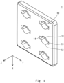
- Fig. 1 is a perspective view schematically showing a cover used for an electronic apparatus according to this example embodiment.
- Fig. 2 is a front view schematically showing the cover used for the electronic apparatus according to this example embodiment.
- a three-dimensional (XYZ) coordinate system is used to clarify the description.
- the X-axis (a first direction) extends in parallel to the surface of the cover
- the Y-axis (a second direction) extends in parallel to the surface of the cover and in a direction orthogonal to the X-axis.
- the Z-axis extends in a direction orthogonal to the X- and Y-axes.
- a Z-axis positive side is the front side of the cover and a Z-axis negative side is the rear side of the cover.
- a cover 1 shown in Figs. 1 and 2 is used for an electronic apparatus such as a desk telephone and is, for example, made of resin. Examples to which the cover 1 is applied will be described later.
- the cover 1 includes through holes 10 that penetrate the cover 1 in the Z-axis direction. As will be described later, buttons of the electronic apparatus are inserted into the through holes 10.
- each through hole 10 is surrounded by a first arc part 11, a second arc part 12, a first projection part 13, and a second projection part 14 as viewed in the Z-axis direction. Further, each through hole 10 has a point-symmetric shape centered at a predefined point P1 in the cover 1.
- the first arc part 11 is centered at the predefined point P1 and has a first diameter R1.
- the second arc part 12 is disposed so as to be opposed to the first arc part 11 in the X-axis direction. Further, the second arc part 12 is centered at the predefined point P1 and has the first diameter R1.
- the first projection part 13 forms a roughly rectangular area that projects from the ends on the Y-axis positive side of the first and second arc parts 11 and 12, and projects toward the Y-axis positive side with respect to the predefined point P1. That is, the part on the X-axis positive side of the first projection part 13 is roughly parallel to the part on the X-axis negative side thereof, and the part on the Y-axis positive side of the first projection part 13 is roughly orthogonal to the parts on the X-axis positive and negative sides thereof. Further, a straight line connecting the ends on the Y-axis negative side of the parts on the X-axis positive and negative sides of the first projection part 13 is roughly parallel to the part on the Y-axis positive side thereof.
- the second projection 14 has a shape that is mirror-symmetric to the shape of the first projection part 13 with a straight line that passes through the predefined point P1 and is parallel to the X-axis being the symmetry axis.
- the second projection part 14 forms a roughly rectangular area that projects from the ends on the Y-axis negative side of the first and second arc parts 11 and 12, and projects toward the Y-axis negative side with respect to the predefined point P1.
- the part on the X-axis positive side of the second projection part 14 is roughly parallel to the part on the X-axis negative side thereof, and the part on the Y-axis negative side of the second projection part 14 is roughly orthogonal to the parts on the X-axis positive and negative sides thereof. Further, a straight line connecting the ends on the Y-axis positive side of the parts on the X-axis positive and negative sides of the second projection part 14 is roughly parallel to the part on the Y-axis negative side thereof.
- each through hole 10 of the cover 1 which has the above-described shape, can form a circular shape by connecting the first and second arc parts 11 and 12 (indicated by a single-dashed line), and can form a rectangular shape by connecting the first and second projection parts 13 and 14 (indicated by a double-dashed line). Therefore, the buttons of the electronic apparatus can be inserted into the through holes irrespective of whether they are circular buttons or rectangular buttons. Therefore, there is no need to prepare a cover according to the shapes of buttons. Therefore, the versatility of the cover 1 is improved and the manufacturing cost of the electronic apparatus can be reduced.
- the first diameter R1 is preferably roughly equal to the diameter of a corresponding circular button that is planned to be adopted in the electronic apparatus in advance.
- the rectangular shape that is formed by connecting the first and second projection parts 13 and 14 is preferably roughly identical to the shape formed by the peripheral edges of a corresponding rectangular button that is planned to be adopted in the electronic apparatus in advance. In this way, it is possible to improve the design of the external appearance of the electronic apparatus. Further, it is possible to prevent or minimize the formation of gaps between the through holes 10 of the cover 1 and the buttons of the electronic apparatus.
- buttons whose basic forms are circular buttons will be described.
- Fig. 3 is a perspective view schematically showing one of first buttons according to this example embodiment.
- Fig. 4 is a front view schematically showing the first button according to this example embodiment.
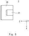
- Fig. 5 is a side view schematically showing the first button according to this example embodiment.
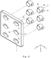
- Fig. 6 is a perspective view schematically showing a state in which the first buttons are inserted into through holes formed in the cover according to this example embodiment.
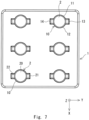
- Fig. 7 is a front view schematically showing a state in which the first buttons have been inserted into the through holes of the cover according to this example embodiment.
- the first button 2 shown in Figs. 3 to 5 adopts a circular button as its basic form and is, for example, made of resin. Specifically, as shown in Figs. 3 to 5 , the first button 2 is formed so as to be point-symmetric around a central axis O1 of the first button 2. Further, the first button 2 includes a body part 20, a first projection part 21, and a second projection part 22.
- the body part 20 has a roughly circular shape as viewed in the Z-axis direction and extends in the Z-axis direction. That is, the body part 20 has a roughly columnar shape extending in the Z-axis direction. Further, the body part 20 has a diameter roughly equal to the first diameter R1 so that it can be inserted into the through hole 10 of the cover 1.
- the first projection part 21 projects from the part on the Z-axis negative side of the body part 20 toward the Y-axis positive side.
- the first projection part 21 has peripheral edges roughly identical to those of the first projection part 13 of the through hole 10 of the cover 1 so that the first projection part 21 can be inserted into the first projection part 13.
- the first projection part 21 has a roughly rectangular shape as viewed in the Z-axis direction and extends in the Z-axis direction so that its shape conforms to the shape of the first projection part 13 of the through hole 10 of the cover 1.
- the first projection part 21 has a roughly rectangular column shape extending in the Z-axis direction.
- the side on the X-axis positive side of the first projection part 21 is roughly parallel to the side on the X-axis negative side thereof, and the side on the Y-axis positive side of the first projection part 21 is roughly orthogonal to the sides on the X-axis positive and negative sides thereof. Further, a straight line connecting the ends on the Y-axis negative side of the sides on the X-axis positive and negative sides of the first projection part 21 is roughly parallel to the side on the Y-axis positive side thereof.
- the second projection part 22 projects from the part on the Z-axis negative side of the body part 20 toward the Y-axis negative side so that the second projection part 22 is opposed to the first projection part 21.
- the second projection part 22 has peripheral edges roughly identical to those of the second projection part 14 of the through hole 10 of the cover 1 so that the second projection part 22 can be inserted into the second projection part 14.
- the second projection part 22 has a roughly rectangular shape as viewed in the Z-axis direction and extends in the Z-axis direction so that its shape conforms to the shape of the second projection part 14 of the through hole 10 of the cover 1.
- the second projection part 22 has a roughly rectangular column shape extending in the Z-axis direction.
- the side on the X-axis positive side of the second projection part 22 is roughly parallel to the side on the X-axis negative side thereof, and the side on the Y-axis negative side of the second projection part 22 is roughly orthogonal to the sides on the X-axis positive and negative sides thereof. Further, a straight line connecting the ends on the Y-axis positive side of the sides on the X-axis positive and negative sides of the second projection part 22 is roughly parallel to the side on the Y-axis negative side thereof.
- the first button 2 Since the first button 2 has a shape conforming to that of the through hole 10 of the cover 1 as described above, it can be inserted into the through hole 10 of the cover 1 as shown in Figs. 6 and 7 . That is, the first button 2, whose basic form is a circular button, can be inserted into the through hole 10 of the cover 1.
- first and second projection parts 21 and 22 of the first button 2 are inserted into the first and second projection parts 13 and 14, respectively, of the through hole 10 of the cover 1. Therefore, it is possible to prevent a foreign substance from entering from any parts of the through hole 10 of the cover 1 other than the part thereof into which the body part 20 of the first button 2 is inserted.
- Fig. 8 is a perspective view schematically showing one of second buttons according to this example embodiment.
- Fig. 9 is a front view schematically showing the second button according to this example embodiment.
- Fig. 10 is a side view schematically showing the second button according to this example embodiment.
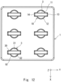
- Fig. 11 is a perspective view schematically showing a state in which the second buttons are inserted into through holes formed in the cover according to this example embodiment.
- Fig. 12 is a front view schematically showing a state in which the second buttons have been inserted into the through holes of the cover according to this example embodiment.
- the second button 3 shown in Figs. 8 to 10 adopts a rectangular button as its basic form and is, for example, made of resin. Specifically, as shown in Figs. 8 to 10 , the second button 3 is formed so as to be point-symmetric around a central axis O2 of the second button 3. Further, the second button 3 includes a body part 30, a first projection part 31, and a second projection part 32.
- the body part 30 has a roughly rectangular shape as viewed in the Z-axis direction and extends in the Z-axis direction.
- the body part 30 has a roughly rectangular column shape extending in the Z-axis direction.
- the peripheral edges on both sides in the Y-axis direction of the body part 30 are formed roughly identical to those of the first and second projection parts 13 and 14 so that they can be inserted into the first and second projection parts 13 and 14 of the through hole 10 of the cover 1. That is, the shape of the body part 30 conforms to a rectangular shape that is formed by connecting the first and second projection parts 13 and 14 of the through hole 10 of the cover 1 as viewed in the Z-axis direction.
- the first projection part 31 projects from the part on the Z-axis negative side of the body part 30 toward the X-axis negative side. Further, the first projection part 31 has a peripheral edge roughly identical to that of the first arc part 11 of the through hole 10 of the cover 1 as viewed in the Z-axis direction so that it can be inserted into the first arc part 11 of the through hole 10 of the cover 1.
- the first projection part 31 has an arcuate column shape in which an arcuate projection surrounded by an arc part 31a that is centered at the central axis O2 of the second button 3 and has a diameter roughly equal to the first diameter R1 and the side on the X-axis negative side of the body part 30 extends in the Z-axis direction.
- the second projection part 32 projects from the part on the Z-axis negative side of the body part 30 toward the X-axis positive side so that it is opposed to the first projection part 31. Further, the second projection part 32 has a peripheral edge roughly identical to that of the second arc part 12 of the through hole 10 of the cover 1 as viewed in the Z-axis direction so that it can be inserted into the second arc part 12 of the through hole 10 of the cover 1.
- the second projection part 32 has an arcuate column shape in which an arcuate projection surrounded by an arc part 32a that is centered at the central axis O2 of the second button 3 and has a diameter roughly equal to the first diameter R1 and the side on the X-axis positive side of the body part 30 extends in the Z-axis direction.
- the second button 3 Since the second button 3 has a shape conforming to that of the through hole 10 of the cover 1 as described above, it can be inserted into the through hole 10 of the cover 1 as shown in Figs. 11 and 12 . That is, the second button 3, whose basis form is a rectangular shape, can also be inserted into the through hole 10 of the cover 1.
- first and second projection parts 31 and 32 of the second button 3 are inserted into the first and second arc parts 11 and 12, respectively, of the through hole 10 of the cover 1. Therefore, it is possible to prevent a foreign substance from entering from any parts of the through hole 10 of the cover 1 other than the part thereof into which the body part 30 of the second button 3 is inserted.
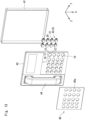
- Fig. 13 is an exploded view schematically showing a desk telephone in which a cover and first buttons according to this example embodiment are used.
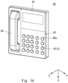
- Fig. 14 is an assembly diagram schematically showing the desk telephone in which the cover and the first buttons according to the example embodiment are used.
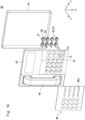
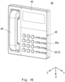
- Fig. 15 is an exploded view schematically showing a desk telephone in which a cover and second buttons according to this example embodiment are used.
- Fig. 16 is an assembly diagram schematically showing the desk telephone in which the cover and the second buttons according to this example embodiment are used.
- a cover 1 according to this example embodiment can be applied to at least a part of a cover of a desk telephone 40, which is an example of the electronic apparatus.
- the desk telephone 40 includes a housing 41 in which a circuit board or the like for implementing functions as the desk telephone 40 is disposed, a first cover 42 a part of which the cover 1 according to this example embodiment is applied to, buttons 43, and a handset unit 44. Note that since the details of the desk telephone 40 are not essential to the present disclosure, descriptions thereof will be omitted.
- the cover 1 according to this example embodiment is applied to a part of the first cover 42, there is no need to change the design of the first cover 42 irrespective of whether circular buttons or rectangular buttons are adopted as the buttons 43 of the desk telephone 40. Therefore, it is possible to reduce the manufacturing cost of the desk telephone 40, which is the electronic apparatus.
- buttons 43 it is possible to suitably use, as the buttons 43, the above-described first buttons 2, whose basic forms are circular buttons, and/or the second buttons 3, whose basic forms are rectangular buttons. As a result, it is possible to prevent foreign substances from entering from any parts of the through holes 10 of the first cover 42 other than the parts thereof into which the body parts of the buttons are inserted.
- the desk telephone 40 preferably includes a second cover 45 that covers the first and second projection parts 13 and 14 of the through holes 10 formed in the first cover 42.
- the second cover 45 circular or rectangular through holes 45a having shapes conforming to the shapes of the parts on the Z-axis positive side of the buttons 43 are formed so that the parts on the Z-axis positive side of the buttons 43 are inserted thereinto.
- the second cover 45 covers the first and second projection parts 13 and 14 of the through holes 10 formed in the first cover 42 in a state where the ends on the Z-axis positive side of the buttons 43 are inserted into these through holes 45a.
- cover 1 of the above-described example embodiment is applied to the first cover 42 of the desk telephone 40, it can be applied to any electronic apparatus that is operated by using either circular buttons or rectangular buttons.
Landscapes
- Engineering & Computer Science (AREA)
- Signal Processing (AREA)
- Microelectronics & Electronic Packaging (AREA)
- Telephone Set Structure (AREA)
- Casings For Electric Apparatus (AREA)
- Push-Button Switches (AREA)
Claims (4)
- Elektronische Vorrichtung (40), die eine erste Abdeckung (1) und einen Knopf (2) aufweist, wobeidie erste Abdeckung (1) ein Durchgangsloch (10) aufweist, in das der Knopf (2) eingesetzt ist,das Durchgangsloch (10) umgeben ist von:einem ersten Bogenteil (11), der an einem vordefinierten Punkt zentriert ist;einem zweiten Bogenteil (12), der so angeordnet ist, dass er dem ersten Bogenteil (11) in einer ersten Richtung parallel zu einer Oberfläche der ersten Abdeckung (1) gegenüberliegt, wobei der zweite Bogenteil (12) an dem vordefinierten Punkt zentriert ist und einen Durchmesser aufweist, der gleich dem des ersten Bogenteils (11) ist;einen ersten Vorsprungsteil (13), der einen rechteckigen Bereich bildet, der von einem Ende des ersten Bogenteils (11) und einem Ende des zweiten Bogenteils (12) vorsteht, wobei der rechteckige Bereich in Bezug auf den vordefinierten Punkt in einer zweiten Richtung nach außen vorsteht, wobei die zweite Richtung parallel zur Oberfläche der ersten Abdeckung (1) und orthogonal zur ersten Richtung ist; undeinen zweiten Vorsprungsteil (14), der einen rechteckigen Bereich bildet, der vom anderen Ende des ersten Bogenteils (11) und dem anderen Ende des zweiten Bogenteils (12) vorsteht, wobei der rechteckige Bereich in Bezug auf den vordefinierten Punkt in der zweiten Richtung nach außen vorsteht, undder Knopf (2) aufweist:einen kreisförmigen säulenförmige Körperteil (20) mit einem Durchmesser, der gleich dem des ersten und des zweiten Bogenteils (11, 12) der ersten Abdeckung (1) ist;einen ersten Vorsprungsteil (21) mit einer Umfangskante, die mit der eines ersten Vorsprungsteils (13) der ersten Abdeckung (1) identisch ist, wobei der erste Vorsprungsteil (21) ein rechteckiger säulenförmiger Vorsprung ist, der in einer ersten radialen Richtung von einem axialen Ende des kreisförmigen säulenförmigen Körperteils (20) vorsteht, das sich auf einer Innenseite der elektronischen Vorrichtung (40) befindet; undeinen zweiten Vorsprungsteil (22) mit einer Umfangskante, die mit der des zweiten Vorsprungsteils (14) der ersten Abdeckung (1) identisch ist, wobei der zweite Vorsprungsteil (22) ein rechteckiger säulenförmiger Vorsprung ist, der in einer zweiten radialen Richtung entgegengesetzt zur ersten radialen Richtung vom axialen Ende des kreisförmigen säulenförmigen Körperteils (20) vorsteht, der auf der Innenseite der elektronischen Vorrichtung (40) angeordnet ist, so dass der zweite Vorsprungsteil (22) dem ersten Vorsprungsteil (21) in der zweiten Richtung entgegengesetzt ist.
- Elektronische Vorrichtung (40) nach Anspruch 1, das ferner eine zweite Abdeckung (45) aufweist, wobeidie zweite Abdeckung (45) ein Durchgangsloch (45a) aufweist, in das ein anderes axiales Ende des kreisförmigen säulenförmigen Körperteils (20) des Knopfes (2) eingesetzt ist, das sich an einer Außenseite der elektronischen Vorrichtung (40) befindet; unddie zweite Abdeckung (45) derart konfiguriert ist, dass sie die erste Abdeckung (1) abdeckt und den ersten und zweiten Vorsprungsteil (13, 14) der ersten Abdeckung (1) abdeckt.
- Elektronische Vorrichtung (40), die eine erste Abdeckung (1) und einen Knopf (3) aufweist, wobeidie erste Abdeckung (1) ein Durchgangsloch (10) aufweist, in das der Knopf (3) eingesetzt ist,das Durchgangsloch (10) umgeben ist von:einem ersten Bogenteil (11), der an einem vordefinierten Punkt zentriert ist;einem zweiten Bogenteil (12), der so angeordnet ist, dass er dem ersten Bogenteil (11) in einer ersten Richtung parallel zu einer Oberfläche der ersten Abdeckung (1) gegenüberliegt, wobei der zweite Bogenteil (12) an dem vordefinierten Punkt zentriert ist und einen Durchmesser aufweist, der gleich dem des ersten Bogenteils (11) ist;einen ersten Vorsprungsteil (13), der einen rechteckigen Bereich bildet, der von einem Ende des ersten Bogenteils (11) und einem Ende des zweiten Bogenteils (12) vorsteht, wobei der rechteckige Bereich in Bezug auf den vordefinierten Punkt in einer zweiten Richtung nach außen vorsteht, wobei die zweite Richtung parallel zur Oberfläche der ersten Abdeckung (1) und orthogonal zu der ersten Richtung ist; undeinen zweiten Vorsprungsteil (14), der einen rechteckigen Bereich bildet, der vom anderen Ende des ersten Bogenteils (11) und dem anderen Ende des zweiten Bogenteils (12) vorsteht, wobei der rechteckige Bereich in Bezug auf den vordefinierten Punkt in der zweiten Richtung nach außen vorsteht, undder Knopf (3) aufweist:einen rechteckigen, säulenförmigen Körperteil (30), der auf beiden Seiten in der zweiten Richtung Umfangskanten aufweist, wobei die Umfangskanten mit denen des ersten und des zweiten Vorsprungsteils (13, 14) der ersten Abdeckung (1) identisch sind;einen ersten Vorsprungsteil (31) mit einer Umfangskante, die identisch ist mit der eines ersten Bogenteils (11) der ersten Abdeckung (1), wobei der erste Vorsprungsteil (31) ein bogenförmiger säulenförmiger Vorsprung ist, der in einer ersten radialen Richtung von einem axialen Ende des rechteckigen säulenförmigen Körperteils (30) vorsteht, das sich an einer Innenseite der elektronischen Vorrichtung (40) befindet; undeinen zweiten Vorsprungsteil (32) mit einer Umfangskante, die identisch mit der eines zweiten Bogenteils (12) der ersten Abdeckung (1) ist, wobei der zweite Vorsprungsteil (32) ein bogenförmiger säulenförmiger Vorsprung ist, der in einer zweiten radialen Richtung entgegengesetzt zur ersten radialen Richtung vom axialen Ende des rechteckigen säulenförmigen Körperteils (30) vorsteht, der auf einer Innenseite der elektronischen Vorrichtung (40) angeordnet ist, so dass der zweite Vorsprungsteil (32) dem ersten Vorsprungsteil (31) in der ersten Richtung entgegengesetzt ist.
- Elektronische Vorrichtung (40) nach Anspruch 3, die ferner eine zweite Abdeckung (45) aufweist, wobeidie zweite Abdeckung (45) ein Durchgangsloch (45a) aufweist, in das ein anderes axiales Ende des rechteckigen säulenförmigen Körperteils (30) des Knopfes (3) eingesetzt ist, das sich an einer Außenseite des elektronischen Geräts (40) befindet; unddie zweite Abdeckung (45) derart konfiguriert ist, dass sie die erste Abdeckung (1) abdeckt und die ersten und zweiten Bogenteile (11, 12) der ersten Abdeckung (1) abdeckt.
Applications Claiming Priority (2)
| Application Number | Priority Date | Filing Date | Title |
|---|---|---|---|
| JP2019008372A JP6669371B1 (ja) | 2019-01-22 | 2019-01-22 | 電子機器のカバー及び電子機器 |
| PCT/JP2019/048954 WO2020153043A1 (ja) | 2019-01-22 | 2019-12-13 | 電子機器のカバー及び電子機器 |
Publications (4)
| Publication Number | Publication Date |
|---|---|
| EP3706397A1 EP3706397A1 (de) | 2020-09-09 |
| EP3706397A4 EP3706397A4 (de) | 2021-06-23 |
| EP3706397B1 true EP3706397B1 (de) | 2024-08-07 |
| EP3706397C0 EP3706397C0 (de) | 2024-08-07 |
Family
ID=70000702
Family Applications (1)
| Application Number | Title | Priority Date | Filing Date |
|---|---|---|---|
| EP19886037.1A Active EP3706397B1 (de) | 2019-01-22 | 2019-12-13 | Elektronische ausrüstung mit abdeckung |
Country Status (6)
| Country | Link |
|---|---|
| US (1) | US11395426B2 (de) |
| EP (1) | EP3706397B1 (de) |
| JP (1) | JP6669371B1 (de) |
| CN (1) | CN111727670B (de) |
| AU (1) | AU2019369207B2 (de) |
| WO (1) | WO2020153043A1 (de) |
Family Cites Families (16)
| Publication number | Priority date | Publication date | Assignee | Title |
|---|---|---|---|---|
| JPS6370629U (de) * | 1986-10-29 | 1988-05-12 | ||
| JPH0289882U (de) | 1988-12-28 | 1990-07-17 | ||
| FR2740913B1 (fr) * | 1995-11-07 | 1997-12-05 | Framatome Connectors France | Element de maintien et de contact et connecteur le comprenant |
| JPH11306903A (ja) * | 1998-04-23 | 1999-11-05 | Canon Inc | 操作パネル |
| TWM245687U (en) * | 2003-07-11 | 2004-10-01 | Hon Hai Prec Ind Co Ltd | Repalceable panel for handset |
| GB2409596A (en) * | 2003-12-23 | 2005-06-29 | Nokia Corp | Handset with squeezable body |
| TWI289280B (en) * | 2006-01-24 | 2007-11-01 | Chunghwa Picture Tubes Ltd | Mounting button used in display module |
| CN201263263Y (zh) * | 2008-09-28 | 2009-06-24 | 姚国祥 | 一种适合安装多种形状按键的控制器外壳 |
| TWM358501U (en) * | 2008-11-12 | 2009-06-01 | Altek Corp | Case structure with keypad |
| CN201303361Y (zh) * | 2008-11-28 | 2009-09-02 | 高艺 | 多功能电话 |
| CN102118927A (zh) * | 2009-12-30 | 2011-07-06 | 深圳富泰宏精密工业有限公司 | 便携式电子装置壳体装配结构 |
| JP5587143B2 (ja) * | 2010-11-15 | 2014-09-10 | 株式会社三谷バルブ | 連続作動モード設定機構および、この連続作動モード設定機構を備えたエアゾール式製品 |
| CN205725872U (zh) * | 2016-03-17 | 2016-11-23 | 中兴通讯股份有限公司 | 一种按键和终端 |
| JP6729849B2 (ja) * | 2016-07-22 | 2020-07-29 | 株式会社デンソーテン | 操作ユニットの組み付け構造 |
| CN206136021U (zh) * | 2016-11-18 | 2017-04-26 | 安徽国越电子科技有限公司 | 一种ip音频电话终端 |
| JP6979804B2 (ja) | 2017-06-20 | 2021-12-15 | キヤノン株式会社 | 情報処理装置とその制御方法、及びプログラム |
-
2019
- 2019-01-22 JP JP2019008372A patent/JP6669371B1/ja active Active
- 2019-12-13 EP EP19886037.1A patent/EP3706397B1/de active Active
- 2019-12-13 US US16/762,973 patent/US11395426B2/en active Active
- 2019-12-13 CN CN201980005915.2A patent/CN111727670B/zh active Active
- 2019-12-13 AU AU2019369207A patent/AU2019369207B2/en active Active
- 2019-12-13 WO PCT/JP2019/048954 patent/WO2020153043A1/ja not_active Ceased
Also Published As
| Publication number | Publication date |
|---|---|
| AU2019369207A1 (en) | 2020-08-06 |
| US11395426B2 (en) | 2022-07-19 |
| AU2019369207B2 (en) | 2022-12-08 |
| CN111727670A (zh) | 2020-09-29 |
| US20210219447A1 (en) | 2021-07-15 |
| JP6669371B1 (ja) | 2020-03-18 |
| EP3706397A1 (de) | 2020-09-09 |
| EP3706397A4 (de) | 2021-06-23 |
| EP3706397C0 (de) | 2024-08-07 |
| CN111727670B (zh) | 2021-09-03 |
| WO2020153043A1 (ja) | 2020-07-30 |
| JP2020119951A (ja) | 2020-08-06 |
Similar Documents
| Publication | Publication Date | Title |
|---|---|---|
| RU2654345C2 (ru) | Антенное устройство для портативного терминала | |
| JP2017527063A (ja) | Usbソケットコネクタおよびそれを備える電子装置 | |
| US20140079240A1 (en) | Bluetooth headset | |
| JP2008218526A (ja) | シールドケースおよび電子機器 | |
| EP3706397B1 (de) | Elektronische ausrüstung mit abdeckung | |
| JP2000299723A (ja) | 携帯無線機器の音響部品実装構造 | |
| CA3084415C (en) | Cover for electronic apparatus and electronic apparatus | |
| CN206948600U (zh) | 一种电声转换器及电子设备 | |
| WO2025045237A1 (zh) | 耳机盒及耳机盒组件 | |
| JP5976162B1 (ja) | 車両用盗難防止装置 | |
| TW202239239A (zh) | 連接系統 | |
| JP2000152395A (ja) | ネットワーク部品の取付構造 | |
| CN218888673U (zh) | 一种无线耳机及耳机组件 | |
| CN219485710U (zh) | 车载机器人 | |
| KR20150026661A (ko) | 커넥터 장치 | |
| CN112271900B (zh) | 线性振动马达和电子设备 | |
| CN213186532U (zh) | 扬声器单体、扬声器模组和耳机装置 | |
| CN211106418U (zh) | 一种打印机 | |
| JP6606152B2 (ja) | 電子機器及び電子機器システム | |
| TW202239260A (zh) | 存取點 | |
| CN110390959B (zh) | 一种车载娱乐系统 | |
| JPH0883984A (ja) | 筐体構造 | |
| WO2016095917A1 (en) | A docking system for a mobile electronic device | |
| CN105933812B (zh) | 一种耳机座以及终端设备 | |
| KR20220145177A (ko) | 배터리 단자 접속 구조를 구비한 리모컨 |
Legal Events
| Date | Code | Title | Description |
|---|---|---|---|
| STAA | Information on the status of an ep patent application or granted ep patent |
Free format text: STATUS: UNKNOWN |
|
| STAA | Information on the status of an ep patent application or granted ep patent |
Free format text: STATUS: THE INTERNATIONAL PUBLICATION HAS BEEN MADE |
|
| PUAI | Public reference made under article 153(3) epc to a published international application that has entered the european phase |
Free format text: ORIGINAL CODE: 0009012 |
|
| STAA | Information on the status of an ep patent application or granted ep patent |
Free format text: STATUS: REQUEST FOR EXAMINATION WAS MADE |
|
| 17P | Request for examination filed |
Effective date: 20200525 |
|
| AK | Designated contracting states |
Kind code of ref document: A1 Designated state(s): AL AT BE BG CH CY CZ DE DK EE ES FI FR GB GR HR HU IE IS IT LI LT LU LV MC MK MT NL NO PL PT RO RS SE SI SK SM TR |
|
| AX | Request for extension of the european patent |
Extension state: BA ME |
|
| STAA | Information on the status of an ep patent application or granted ep patent |
Free format text: STATUS: EXAMINATION IS IN PROGRESS |
|
| A4 | Supplementary search report drawn up and despatched |
Effective date: 20210521 |
|
| RIC1 | Information provided on ipc code assigned before grant |
Ipc: H04M 1/02 20060101AFI20210517BHEP Ipc: H04M 1/23 20060101ALI20210517BHEP |
|
| 17Q | First examination report despatched |
Effective date: 20210616 |
|
| DAV | Request for validation of the european patent (deleted) | ||
| DAX | Request for extension of the european patent (deleted) | ||
| GRAP | Despatch of communication of intention to grant a patent |
Free format text: ORIGINAL CODE: EPIDOSNIGR1 |
|
| STAA | Information on the status of an ep patent application or granted ep patent |
Free format text: STATUS: GRANT OF PATENT IS INTENDED |
|
| INTG | Intention to grant announced |
Effective date: 20240314 |
|
| GRAS | Grant fee paid |
Free format text: ORIGINAL CODE: EPIDOSNIGR3 |
|
| GRAA | (expected) grant |
Free format text: ORIGINAL CODE: 0009210 |
|
| STAA | Information on the status of an ep patent application or granted ep patent |
Free format text: STATUS: THE PATENT HAS BEEN GRANTED |
|
| AK | Designated contracting states |
Kind code of ref document: B1 Designated state(s): AL AT BE BG CH CY CZ DE DK EE ES FI FR GB GR HR HU IE IS IT LI LT LU LV MC MK MT NL NO PL PT RO RS SE SI SK SM TR |
|
| REG | Reference to a national code |
Ref country code: GB Ref legal event code: FG4D |
|
| REG | Reference to a national code |
Ref country code: CH Ref legal event code: EP |
|
| REG | Reference to a national code |
Ref country code: IE Ref legal event code: FG4D |
|
| REG | Reference to a national code |
Ref country code: DE Ref legal event code: R096 Ref document number: 602019056776 Country of ref document: DE |
|
| U01 | Request for unitary effect filed |
Effective date: 20240807 |
|
| U07 | Unitary effect registered |
Designated state(s): AT BE BG DE DK EE FI FR IT LT LU LV MT NL PT SE SI Effective date: 20240822 |
|
| PG25 | Lapsed in a contracting state [announced via postgrant information from national office to epo] |
Ref country code: NO Free format text: LAPSE BECAUSE OF FAILURE TO SUBMIT A TRANSLATION OF THE DESCRIPTION OR TO PAY THE FEE WITHIN THE PRESCRIBED TIME-LIMIT Effective date: 20241107 |
|
| PG25 | Lapsed in a contracting state [announced via postgrant information from national office to epo] |
Ref country code: PL Free format text: LAPSE BECAUSE OF FAILURE TO SUBMIT A TRANSLATION OF THE DESCRIPTION OR TO PAY THE FEE WITHIN THE PRESCRIBED TIME-LIMIT Effective date: 20240807 Ref country code: GR Free format text: LAPSE BECAUSE OF FAILURE TO SUBMIT A TRANSLATION OF THE DESCRIPTION OR TO PAY THE FEE WITHIN THE PRESCRIBED TIME-LIMIT Effective date: 20241108 |
|
| PG25 | Lapsed in a contracting state [announced via postgrant information from national office to epo] |
Ref country code: IS Free format text: LAPSE BECAUSE OF FAILURE TO SUBMIT A TRANSLATION OF THE DESCRIPTION OR TO PAY THE FEE WITHIN THE PRESCRIBED TIME-LIMIT Effective date: 20241207 |
|
| PG25 | Lapsed in a contracting state [announced via postgrant information from national office to epo] |
Ref country code: HR Free format text: LAPSE BECAUSE OF FAILURE TO SUBMIT A TRANSLATION OF THE DESCRIPTION OR TO PAY THE FEE WITHIN THE PRESCRIBED TIME-LIMIT Effective date: 20240807 |
|
| PG25 | Lapsed in a contracting state [announced via postgrant information from national office to epo] |
Ref country code: RS Free format text: LAPSE BECAUSE OF FAILURE TO SUBMIT A TRANSLATION OF THE DESCRIPTION OR TO PAY THE FEE WITHIN THE PRESCRIBED TIME-LIMIT Effective date: 20241107 Ref country code: ES Free format text: LAPSE BECAUSE OF FAILURE TO SUBMIT A TRANSLATION OF THE DESCRIPTION OR TO PAY THE FEE WITHIN THE PRESCRIBED TIME-LIMIT Effective date: 20240807 |
|
| PG25 | Lapsed in a contracting state [announced via postgrant information from national office to epo] |
Ref country code: RS Free format text: LAPSE BECAUSE OF FAILURE TO SUBMIT A TRANSLATION OF THE DESCRIPTION OR TO PAY THE FEE WITHIN THE PRESCRIBED TIME-LIMIT Effective date: 20241107 Ref country code: PL Free format text: LAPSE BECAUSE OF FAILURE TO SUBMIT A TRANSLATION OF THE DESCRIPTION OR TO PAY THE FEE WITHIN THE PRESCRIBED TIME-LIMIT Effective date: 20240807 Ref country code: NO Free format text: LAPSE BECAUSE OF FAILURE TO SUBMIT A TRANSLATION OF THE DESCRIPTION OR TO PAY THE FEE WITHIN THE PRESCRIBED TIME-LIMIT Effective date: 20241107 Ref country code: IS Free format text: LAPSE BECAUSE OF FAILURE TO SUBMIT A TRANSLATION OF THE DESCRIPTION OR TO PAY THE FEE WITHIN THE PRESCRIBED TIME-LIMIT Effective date: 20241207 Ref country code: HR Free format text: LAPSE BECAUSE OF FAILURE TO SUBMIT A TRANSLATION OF THE DESCRIPTION OR TO PAY THE FEE WITHIN THE PRESCRIBED TIME-LIMIT Effective date: 20240807 Ref country code: GR Free format text: LAPSE BECAUSE OF FAILURE TO SUBMIT A TRANSLATION OF THE DESCRIPTION OR TO PAY THE FEE WITHIN THE PRESCRIBED TIME-LIMIT Effective date: 20241108 Ref country code: ES Free format text: LAPSE BECAUSE OF FAILURE TO SUBMIT A TRANSLATION OF THE DESCRIPTION OR TO PAY THE FEE WITHIN THE PRESCRIBED TIME-LIMIT Effective date: 20240807 |
|
| U20 | Renewal fee for the european patent with unitary effect paid |
Year of fee payment: 6 Effective date: 20241227 |
|
| PG25 | Lapsed in a contracting state [announced via postgrant information from national office to epo] |
Ref country code: SM Free format text: LAPSE BECAUSE OF FAILURE TO SUBMIT A TRANSLATION OF THE DESCRIPTION OR TO PAY THE FEE WITHIN THE PRESCRIBED TIME-LIMIT Effective date: 20240807 |
|
| PG25 | Lapsed in a contracting state [announced via postgrant information from national office to epo] |
Ref country code: CZ Free format text: LAPSE BECAUSE OF FAILURE TO SUBMIT A TRANSLATION OF THE DESCRIPTION OR TO PAY THE FEE WITHIN THE PRESCRIBED TIME-LIMIT Effective date: 20240807 |
|
| PG25 | Lapsed in a contracting state [announced via postgrant information from national office to epo] |
Ref country code: SK Free format text: LAPSE BECAUSE OF FAILURE TO SUBMIT A TRANSLATION OF THE DESCRIPTION OR TO PAY THE FEE WITHIN THE PRESCRIBED TIME-LIMIT Effective date: 20240807 |
|
| PLBE | No opposition filed within time limit |
Free format text: ORIGINAL CODE: 0009261 |
|
| STAA | Information on the status of an ep patent application or granted ep patent |
Free format text: STATUS: NO OPPOSITION FILED WITHIN TIME LIMIT |
|
| PG25 | Lapsed in a contracting state [announced via postgrant information from national office to epo] |
Ref country code: MC Free format text: LAPSE BECAUSE OF FAILURE TO SUBMIT A TRANSLATION OF THE DESCRIPTION OR TO PAY THE FEE WITHIN THE PRESCRIBED TIME-LIMIT Effective date: 20240807 |
|
| 26N | No opposition filed |
Effective date: 20250508 |
|
| REG | Reference to a national code |
Ref country code: CH Ref legal event code: PL |
|
| PG25 | Lapsed in a contracting state [announced via postgrant information from national office to epo] |
Ref country code: CH Free format text: LAPSE BECAUSE OF NON-PAYMENT OF DUE FEES Effective date: 20241231 |
|
| PG25 | Lapsed in a contracting state [announced via postgrant information from national office to epo] |
Ref country code: IE Free format text: LAPSE BECAUSE OF NON-PAYMENT OF DUE FEES Effective date: 20241213 |
|
| PG25 | Lapsed in a contracting state [announced via postgrant information from national office to epo] |
Ref country code: RO Free format text: LAPSE BECAUSE OF FAILURE TO SUBMIT A TRANSLATION OF THE DESCRIPTION OR TO PAY THE FEE WITHIN THE PRESCRIBED TIME-LIMIT Effective date: 20240807 |
|
| PGFP | Annual fee paid to national office [announced via postgrant information from national office to epo] |
Ref country code: GB Payment date: 20251219 Year of fee payment: 7 |
|
| U20 | Renewal fee for the european patent with unitary effect paid |
Year of fee payment: 7 Effective date: 20251230 |