EP3705637A1 - Wandmontierbare sanitäre verteiler- und leitungsanschlussvorrichtung mit integrierten ventilen - Google Patents
Wandmontierbare sanitäre verteiler- und leitungsanschlussvorrichtung mit integrierten ventilen Download PDFInfo
- Publication number
- EP3705637A1 EP3705637A1 EP20161143.1A EP20161143A EP3705637A1 EP 3705637 A1 EP3705637 A1 EP 3705637A1 EP 20161143 A EP20161143 A EP 20161143A EP 3705637 A1 EP3705637 A1 EP 3705637A1
- Authority
- EP
- European Patent Office
- Prior art keywords
- valve
- wall
- valve block
- base
- sub
- Prior art date
- Legal status (The legal status is an assumption and is not a legal conclusion. Google has not performed a legal analysis and makes no representation as to the accuracy of the status listed.)
- Granted
Links
Images


Classifications
-
- E—FIXED CONSTRUCTIONS
- E03—WATER SUPPLY; SEWERAGE
- E03C—DOMESTIC PLUMBING INSTALLATIONS FOR FRESH WATER OR WASTE WATER; SINKS
- E03C1/00—Domestic plumbing installations for fresh water or waste water; Sinks
- E03C1/02—Plumbing installations for fresh water
- E03C1/021—Devices for positioning or connecting of water supply lines
- E03C1/023—Devices for positioning or connecting of water supply lines with flow distribution, e.g. diverters
-
- F—MECHANICAL ENGINEERING; LIGHTING; HEATING; WEAPONS; BLASTING
- F16—ENGINEERING ELEMENTS AND UNITS; GENERAL MEASURES FOR PRODUCING AND MAINTAINING EFFECTIVE FUNCTIONING OF MACHINES OR INSTALLATIONS; THERMAL INSULATION IN GENERAL
- F16K—VALVES; TAPS; COCKS; ACTUATING-FLOATS; DEVICES FOR VENTING OR AERATING
- F16K27/00—Construction of housing; Use of materials therefor
-
- F—MECHANICAL ENGINEERING; LIGHTING; HEATING; WEAPONS; BLASTING
- F16—ENGINEERING ELEMENTS AND UNITS; GENERAL MEASURES FOR PRODUCING AND MAINTAINING EFFECTIVE FUNCTIONING OF MACHINES OR INSTALLATIONS; THERMAL INSULATION IN GENERAL
- F16K—VALVES; TAPS; COCKS; ACTUATING-FLOATS; DEVICES FOR VENTING OR AERATING
- F16K31/00—Actuating devices; Operating means; Releasing devices
- F16K31/02—Actuating devices; Operating means; Releasing devices electric; magnetic
-
- F—MECHANICAL ENGINEERING; LIGHTING; HEATING; WEAPONS; BLASTING
- F16—ENGINEERING ELEMENTS AND UNITS; GENERAL MEASURES FOR PRODUCING AND MAINTAINING EFFECTIVE FUNCTIONING OF MACHINES OR INSTALLATIONS; THERMAL INSULATION IN GENERAL
- F16K—VALVES; TAPS; COCKS; ACTUATING-FLOATS; DEVICES FOR VENTING OR AERATING
- F16K51/00—Other details not peculiar to particular types of valves or cut-off apparatus
-
- E—FIXED CONSTRUCTIONS
- E03—WATER SUPPLY; SEWERAGE
- E03C—DOMESTIC PLUMBING INSTALLATIONS FOR FRESH WATER OR WASTE WATER; SINKS
- E03C1/00—Domestic plumbing installations for fresh water or waste water; Sinks
- E03C1/02—Plumbing installations for fresh water
- E03C1/05—Arrangements of devices on wash-basins, baths, sinks, or the like for remote control of taps
- E03C1/055—Electrical control devices, e.g. with push buttons, control panels or the like
Definitions
- the invention relates to a wall-mountable sanitary line connection device with a wall-mountable base body, a valve block body which can be fixed to the base body and valves held on the valve block body.
- Line connection devices of this type are used in sanitary engineering, in particular, as an interface between building-side water supply installations on the one hand and end-user equipment such as shower heads and sanitary drainage taps or outlet fittings on washbasins, bathtubs, kitchen sinks and the like on the other. They are available in both surface-mounted and flush-mounted versions, e.g. Commonly used as so-called surface-mounted or flush-mounted installation boxes, in addition to the type considered here with an integrated valve, alternatively in versions without a valve. Such line connection devices are often also used as so-called water sockets.
- wall-mountable is to be understood as meaning that the sanitary line connection device is intended and set up so that it can be mounted on a wall on the building side, specifically on a wall area in which a water installation connection point on the building side is present.
- wall is to be understood in general as a building-side surface which is suitable for the assembly of the line connection device and which can be both an actual vertical wall surface of a building and a ceiling surface or floor surface.
- the laid-open documents are representative of the state of the art, primarily with regard to flush-mounted versions DE 10 2016 214 777 A1 , DE10 2017 100 707 A1 , US 2011/0290356 A1 , DE 10 2004 060 744 A1 , DE 197 02 356 A1 , DE 10 2004 054 642 A1 , DE 196 22 368 A1 , DE 10 2004 060 744 A1 , DE 196 27 571 A1 , US 2009/0057591 A1 , EP 0 844 340 A1 and DE 39 07 586 A1 as well as the patents EP 2 889 522 B1 , US 9,650,768 B2 and US 10,138,619.B2 called, in which line connection devices of this and similar types with one or more integrated valves or without an integrated valve are disclosed.
- the invention is based on the provision of a wall-mountable sanitary line connection device of the type mentioned at the outset the above-mentioned prior art offers improvements in terms of flexibility in use, compact design, manufacturing effort and / or possible uses in modern sanitary systems, including systems with water sockets and systems for sanitary smart home applications.
- This line connection device includes a wall-mountable base body which has a wall-mounting side, a water inlet and a base-side contact surface on a valve block coupling side opposite the wall-mounting side, and a valve block body which has a Distribution chamber with a distribution chamber inlet that can be coupled to the water inlet, a valve block-side contact surface that conforms to the base-side contact surface on a base coupling side and at least three line connection nozzles on a line coupling side opposite the base coupling side, which are arranged next to one another in a row with parallel nozzle longitudinal axes.
- the line connection device contains at least three electrically controllable valves, each of which contains a valve cartridge, each of which has a valve inlet in fluid connection with the distribution chamber and which are held on the valve block body with longitudinal valve cartridge axes parallel to one another, the longitudinal valve cartridge axes being around a center point are arranged offset from one another in a circumferential direction perpendicular to the valve cartridge longitudinal axes.
- three, four or more valves can be arranged in this way.
- the valve block body has a corresponding number of at least three separate fluid guides, each from one of the valve outlets to one of the line connecting pieces and can be fixed with its valve block-side contact surface against the base-side contact surface on the base body.
- the term line connection piece refers to connection pieces both for coupling rigid water-carrying pipes and flexible water-carrying hose lines, e.g. a rigid pipe that leads to a shower body or shower head, or a flexible shower hose that leads to a shower head.
- the line connection stubs form outlet openings each one associated, valve-controlled fluid guide of the line connection device for water supplied via the water inlet, with one or more sanitary end users, such as a shower head or a water outlet fitting, for example in the form of conventional mixer fittings or outlet taps, being able to be coupled to the outlet openings in the desired manner, e.g. a conventional three-channel mixer shower head that is designed to provide different types of spray, or at least three showers and / or outlet taps that can be connected in parallel and optionally or individually supplied with water via the electrical control of the valves.
- the line connection device can be used flexibly for various applications, especially in modern sanitary facilities of the smart home type or in sanitary systems with water sockets.
- electrically controllable valves the water flow in the line connection device can be controlled electrically, which in particular enables remote control of the water flow, so that direct access to the line connection device for actuating the valves is not absolutely necessary.
- the valves can in particular be shut-off valves, alternatively valves of other types, such as mixing valves or changeover valves, for which purpose valves can then have one or more additional valve inlet openings and / or valve outlet openings.
- the line connection device can, if required, be flexibly equipped with a desired valve, which is then held with its valve cartridge on the valve block body. If only one or two valves are required for certain applications, the remaining valves can be kept inactive, or the relevant installation location on the valve block body can remain empty.
- the realization of the line connection device with the line connection pieces arranged in a row next to one another on the one hand and with the arrangement of the valve cartridges offset from one another with their longitudinal axes around a center in a circumferential direction perpendicular to the valve cartridge longitudinal axes on the other hand is advantageous.
- This combines in a particularly advantageous manner a compact arrangement of the three or more valves and thus a correspondingly possible compact design of the line connection device overall with one on the outlet side typically required arrangement of the associated three or more line connection pieces in a line or row next to one another. If only one or two line connectors are required for certain applications, the line connectors that are not required can remain unoccupied and the associated valves can be kept inactive.
- valve block body It is also advantageous that the three or more separate fluid ducts from the respective valve outlet to the associated line connector are integrated in the valve block body, the fluid guides being configured so that the water from the valve cartridges arranged offset in the circumferential direction reaches the line connectors arranged in a row.
- the valve block body rests in a stable manner with its valve block-side contact surface against the base-side contact surface of the base body, with its distribution chamber inlet being coupled fluid-tight to the water inlet of the base body.
- valve cartridges are cylindrical in shape and each have an electrical valve connection unit on a first end face and the valve inlet and the valve outlet on a second end face facing the line coupling side of the valve block body. This represents a favorable division of the electrical connection on the one hand and the fluid connections of the respective valve on the other hand in order to achieve compact designs for the line connection device.
- the valve cartridges can then, for example, be oriented with their first end face facing the base body with the electrical valve connection unit, so that they their other having the valve inlet and the valve outlet are oriented facing forward from a wall surface when the line connection device is attached to the wall surface.
- the valve block body includes a circumferential rubber-elastic retaining ring, and the respective valve has an electrical connection cable extending from the first end face of its valve cartridge, which is passed through a cable guide space between the rubber retaining ring and an adjacent area of the valve block body.
- This can optimize the electrical cable routing for the valves.
- the rubber-elastic retaining ring can also be used for securing against loss of fastening elements, such as screws, which are provided on the valve block body depending on the design of the line connection device.
- the retaining ring can, for example, simply be manufactured in the manner of a rubber sealing ring or O-ring rubber.
- the contact surface on the base side and the contact surface on the valve block side each lie on a spherical shell.
- the valve block body can be aligned in its position relative to the base body as required during assembly on the base body, the two contact surfaces coming into contact with one another functioning as a spherical-shell-shaped alignment joint.
- the valve block is then secured in an aligned position on the base, e.g. by means of a screw connection or another, preferably releasable connection such as a snap-in connection or the like.
- the water inlet opens laterally into the base body at a side area of the base body adjoining the wall attachment side of the base body. This can contribute to the fact that the line connecting device with a relatively small overall depth, i. can be realized relatively small dimensions in the direction perpendicular to the mounting wall surface.
- valve block body has a circular cross section, and the valve cartridge longitudinal axes are arranged within this cross section with equidistant angular spacing in the circumferential direction offset on a common radius. This contributes to a very compact design of the valve block body and thus also of the line connecting device as a whole.
- the base body comprises a wall-mountable base plate and a base body which is fastened to the base plate and has the water inlet.
- the base body can be via the base plate be mounted on a wall surface in a desired manner in a flush or surface mounting technique, the base body in turn being attached to the base plate, for example releasably by means of screws or the like, and the water inlet being prefabricated on it.
- the base body has an empty pipe receptacle for an empty pipe, which can be used to receive one or more electrical lines. This enables a simple electrical cable feed for the electrically controllable valves.
- the base body forms a connection box with a box housing cover.
- the box housing cover protects the interior of the base body including the valves and can also act as an optical cover.
- the connection box is particularly suitable as a flush-mounted installation box for flush-mounted implementations of the line connection device.
- the sanitary line connection device illustrated in the figures is set up for mounting on a building-side wall surface, for example a vertical building wall surface or a ceiling or floor surface, and has a wall-mountable base body 1 which has a wall fastening side 2, a water inlet 3 and a valve block coupling side 6 opposite the wall mounting side 2 contains a base-side contact surface 7. Furthermore, the line connecting device has a valve block body 8 and at least three electrically controllable valves 4 1 , 4 2 , 4 3 , each of which contains a valve cartridge 5 1 , 5 2 , 5 3 , the valve cartridges 5 1 , 5 2 5 3 being parallel to one another Valve cartridge longitudinal axes V L are held on the valve block body 8.
- the valve block body 8 has a distribution chamber 9 with a distribution chamber inlet 9a that can be coupled to the water inlet 3, a valve block-side contact surface 10 on a base coupling side 11 that conforms to the base-side contact surface 7 of the base body 1, and at least three line connection pieces 13 1 , 13 2 , 13 3 on one of the base coupling side 11 opposite line coupling side 12.
- the line connecting pieces 13 1 , 13 2 , 13 3 are arranged in a row next to one another with longitudinal nozzle axes S L parallel to one another.
- the valve cartridges 5 1 , 5 2 , 5 3 each have a valve inlet 14 in fluid communication with the distribution chamber 9 of the valve block body 8 and a valve outlet 15.
- the valve cartridges 5 1 , 5 2 , 5 3 are in a special mutual position and orientation on the valve block body 8, namely in such a way that their longitudinal axes V L are offset from one another around a center point M v in a circumferential direction U v perpendicular to the longitudinal axes V L.
- the valve block body 8 has at least three fluid guides 16 1 , 16 2 , 16 3 that are separate from one another and each lead from an associated one of the valve outlets 15 to an associated one of the line connection pieces 13 1 , 13 2 , 13 3 . With its contact surface 10 on the valve block side, the valve block body 8 can be fixed against the contact surface 7 of the base body 1 on the base side and on the base body 1.
- valve cartridges 5 1 , 5 2 , 5 3 are cylindrical in shape as in the example shown and each have an electrical valve connection unit 18 on a first end face 17 and the valve inlet 14 on a second end face 19 facing the line coupling side 12 of the valve block body 8 and the valve outlet 15.
- the valve block body 8 contains, as in the example shown, a circumferentially encircling, rubber-elastic retaining ring 20, and the respective valve 4 1 , 4 2 , 4 3 has an electrical connection unit 18 of its valve cartridge 5 1 , 5 2 , 5 3 outgoing electrical connection cable 21, which is passed through a cable guide space 22 between the retaining ring 20 and an adjacent region of the valve block body 8.
- the connection cables 21 of the valves 4 1 , 4 2 , 4 3 can advantageously be routed, in particular, in the direction away from the first valve end face 17 in the direction of the second valve end face 19.
- the base-side contact surface 7 of the base body 1 and the valve-block-side contact surface 10 of the valve block body 8 each rest on a spherical shell 23, as in FIG Fig. 3 indicated by dashed lines.
- a spherical shell-shaped alignment joint with which the valve block body 8 can be aligned in its position before it is fixed on the base body 1.
- a corresponding alignment template or alignment aid 30 can be used, as shown in Fig. 1 is shown.
- screws 24 for example, as shown, can be used.
- these are four screws 24 arranged offset in the circumferential direction.
- the screws 24 are held captive on the valve block body 8 by means of the retaining ring 20.
- the water inlet 3 opens laterally into the base body 1 at a side region 25 adjoining the wall mounting side 2 of the base body 1. This facilitates the realization of the line connection device with a relatively small overall depth.
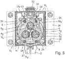
- the valve block body 8 has a circular cross section, in particular from the Fig. 2 and 5 can be seen, within which the valve cartridge longitudinal axes V L are arranged offset with equidistant angular spacing in the circumferential direction Uv on a common radius R V are like in particular from Fig. 5 evident.
- the circumferential angular distance is consequently 120 °, with four or more valves 4 1 , 4 2 , 4 3 , ... it is equal to a corresponding fraction of 360 °. This optimizes a compact arrangement of the valves 4 1 , 4 2 , 4 3 .
- the base body 1 comprises a wall-mountable base plate 26 and a base body 27 which is fastened to the base plate 26, for example by means of screws 28 and which has the water inlet 3.
- the base body 1 can be fastened to a wall surface via the base plate 26, for example as shown using screw connections 29.
- the base plate 26 is in FIG Fig. 1, 2 , 4th and 5 shown in Fig. 3 other components are omitted for better visibility, the screws 28 being shown there as a representative.
- the base body 1 includes an empty pipe receptacle 31 for an empty pipe 32, in which electrical lines or cables can be received, in particular for electrically connecting the valves 4 1 , 4 2 , 4 3 by connecting them to their electrical connection cables 21.
- the base body 1 forms, as in the example shown, a connection box with a box housing cover 33.
- the box housing cover 33 preferably has a collar 33a or cylinder section open in the direction of the line coupling side 12 of the valve block body 8 , which after completion of the wall surface, e.g. by applying a wall plaster or wall tiles flush with an in Fig. 4 schematically indicated, finished wall surface 34 can be cut off or otherwise cut to length flush.
- a sealing body 35 can optionally be used, which ensures that the base body 1 is fluid-tight and at the same time can provide integrated sound decoupling.
- the sealing body 35 can extend with corresponding sections as a flat separation between the base plate 26 and the base body 27 and / or cover the base plate 26 as a flat plate and / or extend between the base plate 26 and the box housing cover 33.
- the invention provides a wall-mountable sanitary line connection device in a very advantageous manner, which has great flexibility in use, can be built very compactly and with relatively little effort and can be used in modern sanitary systems including systems with water outlets and smart home systems.
Landscapes
- Engineering & Computer Science (AREA)
- General Engineering & Computer Science (AREA)
- Mechanical Engineering (AREA)
- Health & Medical Sciences (AREA)
- Life Sciences & Earth Sciences (AREA)
- Hydrology & Water Resources (AREA)
- Public Health (AREA)
- Water Supply & Treatment (AREA)
- Valve Housings (AREA)
- Domestic Plumbing Installations (AREA)
Abstract
Description
- Die Erfindung bezieht sich auf eine wandmontierbare sanitäre Leitungsanschlussvorrichtung mit einem wandmontierbaren Basiskörper, einem an dem Basiskörper festlegbaren Ventilblockkörper und am Ventilblockkörper gehaltenen Ventilen.
- Leitungsanschlussvorrichtungen dieser Art dienen in der Sanitärtechnik insbesondere als Schnittstelle zwischen gebäudeseitigen Wasserversorgungsinstallationen einerseits und Endverbrauchereinrichtungen, wie Duschbrausen und sanitäre Auslaufhähne bzw. Auslaufarmaturen an Waschtischen, Badewannen, Küchenspülen und dgl., andererseits. Sie sind sowohl in Ausführungen vom Aufputztyp als auch in Ausführungen vom Unterputztyp z.B. als sogenannte Aufputz- bzw. Unterputz-Einbaukästen gebräuchlich, neben dem vorliegend betrachteten Typ mit integriertem Ventil alternativ in Ausführungen ohne Ventil. Oftmals werden solche Leitungsanschlussvorrichtungen auch als sogenannte Wassersteckdosen eingesetzt. Unter wandmontierbar ist vorliegend zu verstehen, dass die sanitäre Leitungsanschlussvorrichtung dafür bestimmt und eingerichtet ist, an einer gebäudeseitigen Wand montiert werden zu können, speziell an einem Wandbereich, in dem ein gebäudeseitiger Wasserinstallationsanschlusspunkt vorliegt. Mit dem Begriff Wand ist hierbei vorliegend allgemein eine für die Montage der Leitungsanschlussvorrichtung geeignete gebäudeseitige Fläche zu verstehen, bei der es sich sowohl um eine eigentliche vertikale Wandfläche eines Gebäudes als auch um eine Deckenfläche oder Bodenfläche handeln kann.
- Stellvertretend seien zum Stand der Technik, primär bezüglich Unterputz-Ausführungen, die Offenlegungsschriften
DE 10 2016 214 777 A1 ,DE10 2017 100 707 A1 ,US 2011/0290356 A1 ,DE 10 2004 060 744 A1 ,DE 197 02 356 A1 ,DE 10 2004 054 642 A1 ,DE 196 22 368 A1 ,DE 10 2004 060 744 A1 ,DE 196 27 571 A1 ,US 2009/0057591 A1 ,EP 0 844 340 A1 undDE 39 07 586 A1 sowie die PatentschriftenEP 2 889 522 B1 ,US 9.650.768 B2 US 10.138.619.B2 - Der Erfindung liegt als technisches Problem die Bereitstellung einer wandmontierbaren sanitären Leitungsanschlussvorrichtung der eingangs genannten Art zugrunde, die gegenüber dem oben erwähnten Stand der Technik Verbesserungen hinsichtlich Flexibilität in der Anwendung, kompakter Bauform, Fertigungsaufwand und/oder Einsatzmöglichkeiten in modernen Sanitärsystemen einschließlich Systemen mit Wassersteckdosen und Systemen für sanitäre Smart-Home-Anwendungen bietet.
- Die Erfindung löst dieses Problem durch die Bereitstellung einer wandmontierbaren sanitären Leitungsanschlussvorrichtung mit den Merkmalen des Anspruchs 1. Diese Leitungsanschlussvorrichtung beinhaltet einen wandmontierbaren Basiskörper, der eine Wandbefestigungsseite, einen Wassereinlass und auf einer der Wandbefestigungsseite entgegengesetzten Ventilblockkopplungsseite eine basisseitige Anlagefläche aufweist, und einen Ventilblockkörper, der eine Verteilkammer mit einem an den Wassereinlass ankoppelbaren Verteilkammereinlass, eine zur basisseitigen Anlagefläche konforme, ventilblockseitige Anlagefläche auf einer Basiskopplungsseite und mindestens drei Leitungsanschlussstutzen auf einer der Basiskopplungsseite entgegengesetzten Leitungskopplungsseite aufweist, die mit zueinander parallelen Stutzenlängsachsen in einer Reihe nebeneinanderliegend angeordnet sind.
- Des Weiteren beinhaltet die Leitungsanschlussvorrichtung mindestens drei elektrisch ansteuerbare Ventile, die jeweils eine Ventilkartusche beinhalten, von denen jede einen mit der Verteilkammer in Fluidverbindung stehenden Ventileinlass aufweist und die mit zueinander parallelen Ventilkartuschen-Längsachsen am Ventilblockkörper gehalten sind, wobei die Ventilkartuschen-Längsachsen um einen Mittelpunkt herum in einer zu den Ventilkartuschen-Längsachsen senkrechten Umfangsrichtung zueinander versetzt angeordnet sind. Je nach Bedarf können in dieser Weise drei, vier oder mehr Ventile angeordnet sein. Der Ventilblockkörper weist eine entsprechende Anzahl von mindestens drei voneinander getrennte Fluidführungen jeweils von einem der Ventilauslässe zu einem der Leitungsanschlussstutzen auf und ist mit seiner ventilblockseitigen Anlagefläche gegen die basisseitige Anlagefläche anliegend am Basiskörper festlegbar.
- Unter der Bezeichnung Leitungsanschlussstutzen sind hierbei vorliegend Anschlussstutzen sowohl zum Ankoppeln starrer wasserführender Rohrleitungen als auch flexibler wasserführender Schlauchleitungen zu verstehen, z.B. eine starre Rohrleitung, die zu einem Brausekörper bzw. Brausekopf führt, oder ein zu einem Brausekopf führender, flexibler Brauseschlauch. Die Leitungsanschlussstutzen bilden hierbei Auslassöffnungen je einer zugehörigen, ventilgesteuerten Fluidführung der Leitungsanschlussvorrichtung für über den Wassereinlass zugeführtes Wasser, wobei an die Auslassöffnungen in gewünschter Weise ein oder mehrere sanitäre Endverbraucher, wie eine Duschbrause oder eine Wasserauslaufarmatur beispielsweise in Form üblicher Mischerarmaturen oder Auslaufhähnen, ankoppelbar sind, z.B. eine mindestens dreikanalige herkömmliche Duschbrause, die zur Bereitstellung unterschiedlicher Strahlarten ausgelegt ist, oder mindestens drei parallel anzuschließende und über die elektrische Ansteuerung der Ventile wahlweise bzw. individuell mit Wasser zu versorgende Brausen und/oder Auslaufhähne.
- Durch diesen Aufbau ist die Leitungsanschlussvorrichtung flexibel für verschiedene Anwendungen einsetzbar, gerade auch in modernen Sanitäreinrichtungen vom Smart-Home-Typ oder in Sanitärsystemen mit Wassersteckdosen. Durch die Verwendung elektrisch ansteuerbarer Ventile kann die Wasserführung in der Leitungsanschlussvorrichtung elektrisch gesteuert werden, was insbesondere eine Fernsteuerung der Wasserführung ermöglicht, so dass eine direkte Zugänglichkeit der Leitungsanschlussvorrichtung zum Betätigen der Ventile nicht zwingend erforderlich ist. Bei den Ventilen kann es sich insbesondere Absperrventile handeln, alternativ um Ventile anderen Typs, wie Mischventile oder Umstellventile, wozu Ventile dann entsprechend eine oder mehrere zusätzliche Ventileinlassöffnungen und/oder Ventilauslassöffnungen besitzen können. Durch die Verwendung von Ventilen mit vorzugsweise zylindrischer Ventilkartusche kann die Leitungsanschlussvorrichtung bei Bedarf flexibel mit einem jeweils gewünschten Ventil bestückt werden, das dann mit seiner Ventilkartusche am Ventilblockkörper gehalten ist. Wenn für bestimmte Anwendungen nur ein oder zwei Ventile benötigt werden, können die restlichen Ventile inaktiv gehalten werden, oder der betreffende Einbauplatz am Ventilblockkörper kann unbestückt bleiben.
- Vorteilhaft ist des Weiteren die Realisierung der Leitungsanschlussvorrichtung mit den in einer Reihe nebeneinander angeordneten Leitungsanschlussstutzen einerseits und mit der mit ihren Längsachsen um einen Mittelpunkt herum in einer zu den Ventilkartuschen-Längsachsen senkrechten Umfangsrichtung zueinander versetzten Anordnung der Ventilkartuschen andererseits. Dies kombiniert in besonders günstiger Weise eine kompakte Anordnung der drei oder mehr Ventile und damit eine entsprechend mögliche kompakte Bauform der Leitungsanschlussvorrichtung insgesamt mit einer austrittsseitig typischerweise geforderten Anordnung der zugehörigen drei oder mehr Leitungsanschlussstutzen in einer Linie bzw. Reihe nebeneinander. Wenn für bestimmte Anwendungen nur ein oder zwei Leitungsanschlussstutzen benötigt werden, können die nicht benötigten Leitungsanschlussstutzen unbelegt bleiben und die zugehörigen Ventile inaktiv gehalten werden.
- Weiter vorteilhaft ist, dass in den Ventilblockkörper die drei oder mehr voneinander getrennten Fluidführungen vom jeweiligen Ventilauslass zum zugeordneten Leitungsanschlussstutzen integriert sind, wobei die Fluidführungen so konfiguriert sind, dass das Wasser aus den in Umfangsrichtung versetzt angeordneten Ventilkartuschen zu den in einer Reihe angeordneten Leitungsanschlussstutzen gelangt. Der Ventilblockkörper liegt im montierten Zustand stabil mit seiner ventilblockseitigen Anlagefläche gegen die basisseitige Anlagefläche des Basiskörpers an, wobei sein Verteilkammereinlass fluiddicht an den Wassereinlass des Basiskörpers angekoppelt ist.
- In einer Weiterbildung der Erfindung sind die Ventilkartuschen von zylindrischer Form und weisen jeweils an einer ersten Stirnseite eine elektrische Ventilanschlusseinheit und an einer zweiten, der Leitungskopplungsseite des Ventilblockkörpers zugewandten Stirnseite den Ventileinlass und den Ventilauslass auf. Dies stellt eine zur Erzielung kompakter Bauformen für die Leitungsanschlussvorrichtung günstige Aufteilung des elektrischen Anschlusses einerseits und der Fluidanschlüsse des jeweiligen Ventils andererseits dar. Am Ventilblockkörper können die Ventilkartuschen dann beispielsweise mit ihrer die elektrische Ventilanschlusseinheit aufweisenden ersten Stirnseite dem Basiskörper zugewandt orientiert sein, so dass sie mit ihrer den Ventileinlass und den Ventilauslass aufweisenden anderen von einer Wandfläche nach vorn weisend orientiert sind, wenn die Leitungsanschlussvorrichtung an der Wandfläche angebracht ist.
- In einer Weiterbildung der Erfindung beinhaltet der Ventilblockkörper einen umfangsseitig umlaufenden gummielastischen Haltering, und das jeweilige Ventil weist einen von der ersten Stirnseite seiner Ventilkartusche abgehendes elektrisches Anschlusskabel auf, das durch einen Kabelführungszwischenraum zwischen dem Gummihaltering und einem benachbarten Bereich des Ventilblockkörpers hindurchgeführt ist. Dies kann die elektrische Kabelführung für die Ventile optimieren. Insbesondere ist es mit dieser Maßnahme nicht notwendig, dass die Ventilkartuschen an ihrer ersten Stirnseite, an der sich ihre elektrische Ventilanschlusseinheit befindet, für elektrische Kontaktierungsmaßnahmen zugänglich bleiben, wenn der Ventilblockkörper am Basiskörper festgelegt ist. Diese elektrischen Kontaktierungsmaßnahmen können durch diese Maßnahme an einer leichter zugänglichen Stelle der Leitungsanschlussvorrichtung vorgenommen werden. Bei Bedarf kann der gummielastische Haltering zusätzlich zur verliergesicherten Halterung von Befestigungselementen, wie Schrauben, dienen, die je nach Ausführung der Leitungsanschlussvorrichtung am Ventilblockkörper vorgesehen sind. Der Haltering kann z.B. einfach nach Art eines Gummidichtrings bzw. O-Ringgummis gefertigt sein.
- In einer Weiterbildung der Erfindung liegen die basisseitige Anlagefläche und die ventilblockseitige Anlagefläche jeweils auf einer Kugelschale. Dadurch kann der Ventilblocckörper bei der Montage am Basiskörper in seiner Lage relativ zum Basiskörper nach Bedarf ausgerichtet werden, wobei die beiden gegeneinander zur Anlage kommenden Anlageflächen als kugelschalenförmiges Ausrichtgelenk fungieren. Der Ventilblocckörper wird dann in ausgerichteter Lage am Basiskörper festgelegt, z.B. mittels Schraubverbindung oder einer anderen, vorzugsweise lösbaren Verbindung wie einer Rastverbindung oder dgl.
- In einer Weiterbildung der Erfindung mündet der Wassereinlass an einem an die Wandbefestigungsseite des Basiskörpers angrenzenden Seitenbereich des Basiskörpers seitlich in den Basiskörper. Dies kann dazu beitragen, dass sich die Leitungsanschlussvorrichtung mit relativ geringer Bautiefe, d.h. relativ geringer Abmessung in Richtung senkrecht zur Montagewandfläche, realisieren lässt.
- In einer Weiterbildung der Erfindung besitzt der Ventilblockkörper einen kreisförmigen Querschnitt, und die Ventilkartuschen-Längsachsen sind innerhalb dieses Querschnitts mit äquidistantem Winkelabstand in Umfangsrichtung versetzt auf einem gemeinsamen Radius angeordnet. Dies trägt zu einer bei Bedarf sehr kompakten Bauform des Ventilblockkörpers und damit auch der Leitungsanschlussvorrichtung insgesamt bei.
- In einer Weiterbildung der Erfindung umfasst der Basiskörper eine wandmontierbare Basisplatte und einen an der Basisplatte befestigten Sockelkörper, der den Wassereinlass aufweist. Dies stellt eine fertigungstechnisch und montagetechnisch vorteilhafte, mehrteilige Realisierung des Basiskörpers dar. Über die Basisplatte kann der Basiskörper an einer Wandfläche in gewünschter Weise in einer Unterputz- oder einer Aufputz-Montagetechnik montiert werden, wobei der Sockelkörper seinerseits an der Basisplatte z.B. lösbar mittels Schrauben oder dgl. befestigt ist und an ihm der Wassereinlass vorgefertigt ist.
- In einer Weiterbildung der Erfindung besitzt der Basiskörper eine Leerrohraufnahme für ein Leerrohr, das zur Aufnahme einer oder mehrerer elektrischer Leitungen genutzt werden kann. Dies ermöglicht eine einfache elektrische Kabelzuführung für die elektrisch ansteuerbaren Ventile.
- In einer Weiterbildung der Erfindung bildet der Basiskörper eine Anschlussbox mit einem Boxgehäusedeckel. Der Boxgehäusedeckel schützt den Innenraum des Basiskörpers einschließlich der Ventile und kann auch als optische Abdeckung fungieren. Die Anschlussbox eignet sich insbesondere als Unterputz-Einbaukasten für Unterputz-Realisierungen der Leitungsanschlussvorrichtung.
- Vorteilhafte Ausführungsformen der Erfindung sind in den Zeichnungen dargestellt. Diese und weitere vorteilhafte Ausführungsformen der Erfindung werden nachfolgend näher beschrieben. Hierbei zeigen:
- Fig. 1
- eine Perspektivansicht einer wandmontierbaren sanitären Leitungsanschlussvorrichtung,
- Fig. 2
- eine Draufsicht auf die Leitungsanschlussvorrichtung von
Fig. 1 , - Fig. 3
- eine Schnittansicht längs einer Linie III-III in
Fig. 2 ohne Basisplatte, - Fig. 4
- eine Schnittansicht längs einer Linie IV-IV in
Fig. 2 und - Fig. 5
- eine Schnittansicht längs einer Linie V-V in
Fig. 4 . - Die in den Figuren veranschaulichte sanitäre Leitungsanschlussvorrichtung ist zur Montage an einer gebäudeseitigen Wandfläche, z.B. einer vertikalen Gebäudewandfläche oder einer Decken- oder Bodenfläche, eingerichtet und weist einen wandmontierbaren Basiskörper 1 auf, der eine Wandbefestigungsseite 2, einen Wassereinlass 3 und auf einer der Wandbefestigungsseite 2 entgegengesetzten Ventilblockkopplungsseite 6 eine basisseitige Anlagefläche 7 beinhaltet. Des Weiteren besitzt die Leitungsanschlussvorrichtung einen Ventilblockkörper 8 und mindestens drei elektrisch ansteuerbare Ventile 41, 42, 43, die jeweils eine Ventilkartusche 51, 52, 53 beinhalten, wobei die Ventilkartuschen 51, 52 53 mit zueinander parallelen Ventilkartuschen-Längsachsen VL am Ventilblockkörper 8 gehalten sind.
- Der Ventilblockkörper 8 weist eine Verteilkammer 9 mit einem an den Wassereinlass 3 ankoppelbaren Verteilkammereinlass 9a, eine zur basisseitigen Anlagefläche 7 des Basiskörpers 1 konforme, ventilblockseitige Anlagefläche 10 auf einer Basiskopplungsseite 11 und mindestens drei Leitungsanschlussstutzen 131, 132, 133 auf einer der Basiskopplungsseite 11 entgegengesetzten Leitungskopplungsseite 12 auf. Dabei sind die Leitungsanschlussstutzen 131, 132, 133 mit zueinander parallelen Stutzenlängsachsen SL in einer Reihe nebeneinanderliegend angeordnet.
- Die Ventilkartuschen 51, 52, 53 besitzen jeweils einen mit der Verteilkammer 9 des Ventilblockkörpers 8 in Fluidverbindung stehenden Ventileinlass 14 sowie einen Ventilauslass 15. Die Ventilkartuschen 51, 52, 53 sind in einer speziellen gegenseitigen Lage und Orientierung am Ventilblockkörper 8 gehalten, nämlich derart, dass sie mit ihren Längsachsen VL um einen Mittelpunkt Mv herum in einer zu den Längsachsen VL senkrechten Umfangsrichtung Uv zueinander versetzt angeordnet sind.
- Der Ventilblockkörper 8 weist mindestens drei voneinander getrennte Fluidführungen 161, 162, 163 auf, die jeweils von einem zugehörigen der Ventilauslässe 15 zu einem zugehörigen der Leitungsanschlussstutzen 131, 132, 133 führen. Mit seiner ventilblockseitigen Anlagefläche 10 ist der Ventilblockkörper 8 gegen die basisseitige Anlagefläche 7 des Basiskörpers 1 anliegend am Basiskörper 1 festlegbar.
- In entsprechenden Ausführungen sind die Ventilkartuschen 51, 52, 53 wie beim gezeigten Beispiel von zylindrischer Form und weisen jeweils an einer ersten Stirnseite 17 eine elektrische Ventilanschlusseinheit 18 und an einer zweiten, der Leitungskopplungsseite 12 des Ventilblockkörpers 8 zugewandten Stirnseite 19 den Ventileinlass 14 und den Ventilauslass 15 auf.
- In vorteilhaften Ausführungsformen beinhaltet der Ventilblockkörper 8 wie im gezeigten Beispiel einen umfangsseitig umlaufenden, gummielastischen Haltering 20, und das jeweilige Ventil 41, 42, 43 weist ein von der ersten Stirnseite 17 bzw. seiner dortigen elektrischen Anschlusseinheit 18 seiner Ventilkartusche 51, 52, 53 abgehendes elektrisches Anschlusskabel 21 auf, das durch einen Kabelführungszwischenraum 22 zwischen dem Haltering 20 und einem benachbarten Bereich des Ventilblockkörpers 8 hindurchgeführt ist. Dadurch können die Anschlusskabel 21 der Ventile 41, 42, 43 vorteilhaft insbesondere in Richtung von der ersten Ventilstirnseite 17 weg in Richtung der zweiten Ventilstirnseite 19 geführt werden.
- In vorteilhaften Ausführungen liegen wie beim gezeigten Beispiel die basisseitige Anlagefläche 7 des Basiskörpers 1 und die ventilblockseitige Anlagefläche 10 des Ventilblockkörpers 8 jeweils auf einer Kugelschale 23, wie in
Fig. 3 gestrichelt angedeutet. Dies realisiert beim Anlegen des Ventilblockkörpers 8 an den Basiskörper 1 ein kugelschalenförmiges Ausrichtgelenk, mit dem der Ventilblockkörper 8 vor seiner Fixierung am Basiskörper 1 in seiner Lage ausgerichtet werden kann. Zur Ausrichtung des Ventilblockkörpers 8 insbesondere gegenüber einer Wandfläche und/oder gegenüber der Orientierung von an die Leitungsanschlussstutzen 131, 132, 133 anzuschließenden Endverbraucherleitungen kann z.B. eine entsprechende Ausrichtschablone bzw. Ausrichthilfe 30 verwendet werden, wie sie inFig. 1 gezeigt ist. Zur Festlegung des Ventilblocckörpers 8 am Basiskörper 1 können z.B. wie gezeigt Schrauben 24 verwendet werden. Im gezeigten Beispiel sind dies vier in Umfangsrichtung versetzt angeordnete Schrauben 24. In vorteilhaften Realisierungen sind die Schrauben 24 mittels des Halterings 20 verliersicher am Ventilblockkörper 8 gehalten. - In entsprechenden Ausführungen mündet wie beim gezeigten Beispiel der Wassereinlass 3 an einem an die Wandbefestigungsseite 2 des Basiskörpers angrenzenden Seitenbereich 25 seitlich in den Basiskörper 1. Dies erleichtert eine Realisierung der Leitungsanschlussvorrichtung mit relativ geringer Bautiefe.
- In entsprechenden Ausführungen besitzt der Ventilblockkörper 8 wie beim gezeigten Beispiel einen kreisförmigen Querschnitt, wie insbesondere aus den
Fig. 2 und5 ersichtlich, innerhalb dem die Ventilkartuschen-Längsachsen VL mit äquidistantem Winkelabstand in Umfangsrichtung Uv versetzt auf einem gemeinsamen Radius RV angeordnet sind, wie insbesondere ausFig. 5 ersichtlich. Bei drei Ventilen 41, 42, 43 beträgt der Umfangswinkelabstand folglich 120°, bei vier oder mehr Ventilen 41, 42, 43, ... ist er gleich einem entsprechenden Bruchteil von 360°. Dies optimiert eine bauraumkompakte Anordnung der Ventile 41, 42, 43. - In vorteilhaften Realisierungen umfasst der Basiskörper 1 eine wandmontierbare Basisplatte 26 und einen an der Basisplatte 26 z.B. mittels Schrauben 28 befestigten Sockelkörper 27, der den Wassereinlass 3 aufweist. Über die Basisplatte 26 kann der Basiskörper 1 an einer Wandfläche befestigt werden, beispielsweise wie gezeigt unter Verwendung von Schraubverbindungen 29. Die Basisplatte 26 ist in den
Fig. 1, 2 ,4 und5 gezeigt, inFig. 3 zur besseren Erkennbarkeit anderer Komponenten weggelassen, wobei dort stellvertretend die Schrauben 28 gezeigt sind. - In entsprechenden Realisierungen beinhaltet der Basiskörper 1 eine Leerrohraufnahme 31 für ein Leerrohr 32, in welchem elektrische Leitungen bzw. Kabel aufgenommen werden können, insbesondere zum elektrischen Anschließen der Ventile 41, 42, 43 durch Verbinden mit deren elektrischen Anschlusskabeln 21.
- In entsprechenden Ausführungen bildet der Basiskörper 1 wie im gezeigten Beispiel eine Anschlussbox mit einem Boxgehäusedeckel 33. Der Boxgehäusedeckel 33 besitzt im Fall von Unterputz-Ausführungen, wie im gezeigten Beispiel, vorzugsweise einen in Richtung der Leitungskopplungsseite 12 des Ventilblockkörpers 8 offenen Kragen 33a bzw. Zylinderabschnitt, der nach Fertigstellung der Wandfläche z.B. durch Aufbringen eines Wandputzes oder von Wandkacheln bündig mit einer in
Fig. 4 schematisch angedeuteten, fertigen Wandoberfläche 34 abgeschnitten oder anderweitig bündig abgelängt werden kann. - Optional ist ein Dichtungskörper 35 einsetzbar, der für eine Fluiddichtheit des Basiskörpers 1 sorgt und gleichzeitig eine integrierte Schallentkopplung bereitstellen kann. Der Dichtungskörper 35 kann sich dazu mit entsprechenden Abschnitten als flächige Trennung zwischen der Basisplatte 26 und dem Sockelkörper 27 erstrecken und/oder als flächige Platte die Basisplatte 26 bedecken und/oder sich zwischen der Basisplatte 26 und dem Boxgehäusedeckel 33 erstrecken.
- Wie die gezeigten und die weiteren oben erläuterten Ausführungsbeispiele deutlich machen, stellt die Erfindung in sehr vorteilhafter Weise eine wandmontierbare sanitäre Leitungsanschlussvorrichtung zur Verfügung, die eine große Flexibilität in der Anwendung besitzt, sich sehr kompakt und mit relativ geringem Aufwand bauen lässt und sich in modernen Sanitärsystemen einschließlich Systemen mit Wassersteckdosen und Smart-Home-Systemen nutzbringend verwenden lässt.
Claims (9)
- Wandmontierbare sanitäre Leitungsanschlussvorrichtung mit- einem wandmontierbaren Basiskörper (1), der eine Wandbefestigungsseite (2), einen Wassereinlass (3) und auf einer der Wandbefestigungsseite entgegengesetzten Ventilblockkopplungsseite (6) eine basisseitige Anlagefläche (7) aufweist,- einem Ventilblockkörper (8), der eine Verteilkammer (9) mit einem an den Wassereinlass ankoppelbaren Verteilkammereinlass (9a), eine zur basisseitigen Anlagefläche konforme, ventilblockseitige Anlagefläche (10) auf einer Basiskopplungsseite (11) und mindestens drei Leitungsanschlussstutzen (131, 132, 133) auf einer der Basiskopplungsseite entgegengesetzten Leitungskopplungsseite (12) aufweist, die mit zueinander parallelen Stutzenlängsachsen (SL) in einer Reihe nebeneinanderliegend angeordnet sind, und- mindestens drei elektrisch ansteuerbaren Ventilen (41, 42, 43), die jeweils eine Ventilkartusche (51, 52, 53) beinhalten, von denen jede einen mit der Verteilkammer in Fluidverbindung stehenden Ventileinlass (14) und einen Ventilauslass (15) aufweist und die mit zueinander parallelen Ventilkartuschen-Längsachsen (VL) am Ventilblockkörper gehalten sind, wobei die Ventilkartuschen-Längsachsen um einen Mittelpunkt (MV) herum in einer zu den Ventilkartuschen-Längsachsen senkrechten Umfangsrichtung (Uv) zueinander versetzt angeordnet sind,- wobei der Ventilblockkörper mindestens drei voneinander getrennte Fluidführungen (161, 162, 163) jeweils von einem der Ventilauslässe zu einem der Leitungsanschlussstutzen aufweist und mit seiner ventilblockseitigen Anlagefläche gegen die basisseitige Anlagefläche anliegend am Basiskörper festlegbar ist.
- Wandmontierbare sanitäre Leitungsanschlussvorrichtung nach Anspruch 1, wobei die Ventilkartuschen von zylindrischer Form sind und jeweils an einer ersten Stirnseite (17) eine elektrische Ventilanschlusseinheit (18) und an einer zweiten, der Leitungskopplungsseite des Ventilblockkörpers zugewandten Stirnseite (19) den Ventileinlass und den Ventilauslass aufweisen.
- Wandmontierbare sanitäre Leitungsanschlussvorrichtung nach Anspruch 1 oder 2, wobei der Ventilblockkörper einen umfangsseitig umlaufenden, gummielastischen Haltering (20) aufweist und das jeweilige Ventil ein von der ersten Stirnseite seiner Ventilkartusche abgehendes elektrisches Anschlusskabel (21) aufweist, das durch einen Kabelführungszwischenraum (22) zwischen dem Haltering und einem benachbarten Bereich des Ventilblockkörpers hindurchgeführt ist.
- Wandmontierbare sanitäre Leitungsanschlussvorrichtung nach einem der Ansprüche 1 bis 3, wobei die basisseitige Anlagefläche und die ventilblockseitige Anlagefläche jeweils auf einer Kugelschale (23) liegen.
- Wandmontierbare sanitäre Leitungsanschlussvorrichtung nach einem der Ansprüche 1 bis 4, wobei der Wassereinlass an einem an die Wandbefestigungsseite angrenzenden Seitenbereich (25) seitlich in den Basiskörper mündet.
- Wandmontierbare sanitäre Leitungsanschlussvorrichtung nach einem der Ansprüche 1 bis 5, wobei der Ventilblockkörper einen kreisförmigen Querschnitt besitzt, innerhalb dem die Ventilkartuschen-Längsachsen mit äquidistantem Winkelabstand in Umfangsrichtung versetzt auf einem gemeinsamen Radius (RV) angeordnet sind.
- Wandmontierbare sanitäre Leitungsanschlussvorrichtung nach einem der Ansprüche 1 bis 6, wobei der Basiskörper eine wandmontierbare Basisplatte (26) und einen an der Basisplatte befestigten Sockelkörper (27) aufweist, der den Wassereinlass aufweist.
- Wandmontierbare sanitäre Leitungsanschlussvorrichtung nach einem der Ansprüche 1 bis 7, wobei der Basiskörper eine Leerohraufnahme (31) für ein Leerrohr (32) für eine elektrische Leitung aufweist.
- Wandmontierbare sanitäre Leitungsanschlussvorrichtung nach einem der Ansprüche 1 bis 8, wobei der Basiskörper eine Anschlussbox mit einem Boxgehäusedeckel (33) bildet.
Applications Claiming Priority (1)
| Application Number | Priority Date | Filing Date | Title |
|---|---|---|---|
| DE102019203221.4A DE102019203221A1 (de) | 2019-03-08 | 2019-03-08 | Wandmontierbare sanitäre Leitungsanschlussvorrichtung mit integrierten Ventilen |
Publications (2)
| Publication Number | Publication Date |
|---|---|
| EP3705637A1 true EP3705637A1 (de) | 2020-09-09 |
| EP3705637B1 EP3705637B1 (de) | 2022-01-12 |
Family
ID=69960214
Family Applications (1)
| Application Number | Title | Priority Date | Filing Date |
|---|---|---|---|
| EP20161143.1A Active EP3705637B1 (de) | 2019-03-08 | 2020-03-05 | Wandmontierbare sanitäre verteiler- und leitungsanschlussvorrichtung mit integrierten ventilen |
Country Status (4)
| Country | Link |
|---|---|
| EP (1) | EP3705637B1 (de) |
| CN (1) | CN111664279B (de) |
| DE (1) | DE102019203221A1 (de) |
| ES (1) | ES2910271T3 (de) |
Cited By (1)
| Publication number | Priority date | Publication date | Assignee | Title |
|---|---|---|---|---|
| WO2025087595A1 (de) * | 2023-10-23 | 2025-05-01 | Grohe Ag | Unterputzeinbaukörper für eine sanitärarmatur |
Citations (17)
| Publication number | Priority date | Publication date | Assignee | Title |
|---|---|---|---|---|
| DE3907586A1 (de) | 1989-03-09 | 1990-09-13 | Grohe Armaturen Friedrich | Abschlussvorrichtung fuer mischarmaturen |
| DE19622368A1 (de) | 1996-06-04 | 1997-12-11 | Hansa Metallwerke Ag | Mehrzahl von sanitären Mischarmaturen |
| DE19627571A1 (de) | 1996-07-09 | 1998-01-15 | Grohe Armaturen Friedrich | Unterputz-Anschlußstück |
| EP0844340A1 (de) | 1996-11-23 | 1998-05-27 | Hansa Metallwerke Ag | Unterputz-Einbaukasten für Sanitärarmaturen |
| DE19702356A1 (de) | 1997-01-23 | 1998-07-30 | Grohe Kg Hans | Sanitärarmatur mit einer Rosette |
| US20020144341A1 (en) * | 2001-04-06 | 2002-10-10 | Zieger Claus D. | Spa shower and controller |
| DE102004054642A1 (de) | 2004-11-12 | 2006-05-24 | Hansa Metallwerke Ag | Sanitärarmatur, insbesondere sanitäre Unterputzarmatur |
| DE102004060744A1 (de) | 2004-12-15 | 2006-06-22 | Kludi Gmbh & Co. Kg | Unterputz-Gehäuse für eine Wasseranschlusseinheit |
| KR20070011046A (ko) * | 2005-11-28 | 2007-01-24 | 신한콘트롤밸브 주식회사 | 온수분배기용 온도조절밸브 |
| US20090057591A1 (en) | 2007-09-04 | 2009-03-05 | Izzy Zuhair A | Valve fitting with integral stops |
| US20110290356A1 (en) | 2010-05-26 | 2011-12-01 | Chaota Yang | Device used in digital shower system |
| US9650768B2 (en) | 2012-07-17 | 2017-05-16 | Delta Faucet Company | Shower valve system |
| EP2889522B1 (de) | 2013-12-06 | 2017-07-05 | Kludi GmbH & Co. KG | Wasserschalteinheit |
| DE102016214777A1 (de) | 2016-08-09 | 2018-02-15 | Hansgrohe Se | Anschlusssockel für Sanitärarmatur mit bodenstehender Armatursäule |
| WO2018072876A1 (en) * | 2016-10-20 | 2018-04-26 | Domo Hydros S.R.L. | Encased electronic tap |
| DE102017100707A1 (de) | 2017-01-16 | 2018-07-19 | Grohe Ag | Unterputzbox für einen Armaturenkörper mit einem Befestigungsrahmen |
| US10138619B2 (en) | 2015-03-16 | 2018-11-27 | Fir Italia S.P.A. | Universal embedded system for sanitary faucet components |
Family Cites Families (7)
| Publication number | Priority date | Publication date | Assignee | Title |
|---|---|---|---|---|
| US5549487A (en) * | 1994-12-27 | 1996-08-27 | Sloan Valve Company | Splashproof enclosure for electronic faucet |
| US5860676A (en) * | 1997-06-13 | 1999-01-19 | Swagelok Marketing Co. | Modular block assembly using angled fasteners for interconnecting fluid components |
| DE102013201322B4 (de) * | 2013-01-28 | 2017-08-24 | Hansgrohe Se | Sanitärarmatur mit tastenbetätigbarem Steuerorgan |
| CN203463784U (zh) * | 2013-09-26 | 2014-03-05 | 鹤山市安蒙卫浴科技有限公司 | 一种龙头一体置物台 |
| DE102015226412A1 (de) * | 2015-12-22 | 2017-06-22 | Hansgrohe Se | Schlauchführungsvorrichtung und sanitäre Auszugsschlauch-Armatur |
| CN109723865B (zh) * | 2016-08-22 | 2019-11-29 | 游精学 | 一种暗装龙头阀芯安装结构 |
| DE102017214571B4 (de) * | 2017-08-21 | 2019-02-28 | Hansgrohe Se | Sanitärarmatur mit Wasserführungskanal |
-
2019
- 2019-03-08 DE DE102019203221.4A patent/DE102019203221A1/de not_active Ceased
-
2020
- 2020-03-05 EP EP20161143.1A patent/EP3705637B1/de active Active
- 2020-03-05 ES ES20161143T patent/ES2910271T3/es active Active
- 2020-03-09 CN CN202010158440.5A patent/CN111664279B/zh active Active
Patent Citations (17)
| Publication number | Priority date | Publication date | Assignee | Title |
|---|---|---|---|---|
| DE3907586A1 (de) | 1989-03-09 | 1990-09-13 | Grohe Armaturen Friedrich | Abschlussvorrichtung fuer mischarmaturen |
| DE19622368A1 (de) | 1996-06-04 | 1997-12-11 | Hansa Metallwerke Ag | Mehrzahl von sanitären Mischarmaturen |
| DE19627571A1 (de) | 1996-07-09 | 1998-01-15 | Grohe Armaturen Friedrich | Unterputz-Anschlußstück |
| EP0844340A1 (de) | 1996-11-23 | 1998-05-27 | Hansa Metallwerke Ag | Unterputz-Einbaukasten für Sanitärarmaturen |
| DE19702356A1 (de) | 1997-01-23 | 1998-07-30 | Grohe Kg Hans | Sanitärarmatur mit einer Rosette |
| US20020144341A1 (en) * | 2001-04-06 | 2002-10-10 | Zieger Claus D. | Spa shower and controller |
| DE102004054642A1 (de) | 2004-11-12 | 2006-05-24 | Hansa Metallwerke Ag | Sanitärarmatur, insbesondere sanitäre Unterputzarmatur |
| DE102004060744A1 (de) | 2004-12-15 | 2006-06-22 | Kludi Gmbh & Co. Kg | Unterputz-Gehäuse für eine Wasseranschlusseinheit |
| KR20070011046A (ko) * | 2005-11-28 | 2007-01-24 | 신한콘트롤밸브 주식회사 | 온수분배기용 온도조절밸브 |
| US20090057591A1 (en) | 2007-09-04 | 2009-03-05 | Izzy Zuhair A | Valve fitting with integral stops |
| US20110290356A1 (en) | 2010-05-26 | 2011-12-01 | Chaota Yang | Device used in digital shower system |
| US9650768B2 (en) | 2012-07-17 | 2017-05-16 | Delta Faucet Company | Shower valve system |
| EP2889522B1 (de) | 2013-12-06 | 2017-07-05 | Kludi GmbH & Co. KG | Wasserschalteinheit |
| US10138619B2 (en) | 2015-03-16 | 2018-11-27 | Fir Italia S.P.A. | Universal embedded system for sanitary faucet components |
| DE102016214777A1 (de) | 2016-08-09 | 2018-02-15 | Hansgrohe Se | Anschlusssockel für Sanitärarmatur mit bodenstehender Armatursäule |
| WO2018072876A1 (en) * | 2016-10-20 | 2018-04-26 | Domo Hydros S.R.L. | Encased electronic tap |
| DE102017100707A1 (de) | 2017-01-16 | 2018-07-19 | Grohe Ag | Unterputzbox für einen Armaturenkörper mit einem Befestigungsrahmen |
Cited By (1)
| Publication number | Priority date | Publication date | Assignee | Title |
|---|---|---|---|---|
| WO2025087595A1 (de) * | 2023-10-23 | 2025-05-01 | Grohe Ag | Unterputzeinbaukörper für eine sanitärarmatur |
Also Published As
| Publication number | Publication date |
|---|---|
| DE102019203221A1 (de) | 2020-09-10 |
| CN111664279A (zh) | 2020-09-15 |
| CN111664279B (zh) | 2022-04-22 |
| EP3705637B1 (de) | 2022-01-12 |
| ES2910271T3 (es) | 2022-05-12 |
Similar Documents
| Publication | Publication Date | Title |
|---|---|---|
| EP2775042B1 (de) | Zuleitung zur Kopfdusche einer Dusche | |
| EP3885498B1 (de) | Sanitäre wandeinbau-anschlussboxeinheit mit elektrischer leitungsdurchführung | |
| EP1006242B1 (de) | System von Sanitärarmaturen | |
| EP3486380A1 (de) | Unterputzeinbaukörper für eine sanitärarmatur mit einer kabeldurchführung | |
| EP2041374A1 (de) | Sanitäre unterputzarmatur mit einem basiskörper | |
| AT409775B (de) | Mehrzahl von sanitären mischarmaturen | |
| EP3568531A1 (de) | Unterputzeinbaukörper für eine sanitärarmatur mit einem zweiteiligen gehäuse | |
| AT396605B (de) | Unterputzanschlussstück für sanitärarmaturen | |
| EP3705637B1 (de) | Wandmontierbare sanitäre verteiler- und leitungsanschlussvorrichtung mit integrierten ventilen | |
| DE3826064A1 (de) | Anschlussanordnung fuer eine sanitaere mischarmatur | |
| DE19810699A1 (de) | Wasserarmatur | |
| DE102014216975B4 (de) | Sanitärbrause | |
| DE102014008570A1 (de) | Sanitäre Unterputzarmatur | |
| DE102015012040A1 (de) | Ein Bausatz für eine sanitäre Unterputzarmatur mit einem Verbindungsbauteil und einer Ventilfunktionseinheit | |
| DE3022706A1 (de) | Einloch-mischarmatur, insbesondere fuer den kuechenbereich | |
| DE19943307A1 (de) | Schutzeinrichtung für Sanitärarmaturen | |
| EP1435480B1 (de) | Sanitärarmatur | |
| DE60020519T2 (de) | Parallel gespeistes integriertes Versorgungsnetz für nicht stagnierendes Wasser für Hauswasser und Sprinkleranlage | |
| EP3914783B1 (de) | Armaturenanschlussstück | |
| DE102005002627A1 (de) | Duscheinrichtung | |
| EP3705636B1 (de) | Wandmontierbare sanitäre leitungsanschlussvorrichtung mit integriertem ventil | |
| EP3556951B1 (de) | Sanitärventilblock | |
| EP3848517A1 (de) | Fluidverteilereinheit für sanitäre umstellarmaturen | |
| WO2025190575A1 (de) | Unterputzeinbaukörper für eine sanitärarmatur | |
| DE10125981A1 (de) | Sanitärarmaturenblock |
Legal Events
| Date | Code | Title | Description |
|---|---|---|---|
| PUAI | Public reference made under article 153(3) epc to a published international application that has entered the european phase |
Free format text: ORIGINAL CODE: 0009012 |
|
| STAA | Information on the status of an ep patent application or granted ep patent |
Free format text: STATUS: THE APPLICATION HAS BEEN PUBLISHED |
|
| AK | Designated contracting states |
Kind code of ref document: A1 Designated state(s): AL AT BE BG CH CY CZ DE DK EE ES FI FR GB GR HR HU IE IS IT LI LT LU LV MC MK MT NL NO PL PT RO RS SE SI SK SM TR |
|
| AX | Request for extension of the european patent |
Extension state: BA ME |
|
| STAA | Information on the status of an ep patent application or granted ep patent |
Free format text: STATUS: REQUEST FOR EXAMINATION WAS MADE |
|
| 17P | Request for examination filed |
Effective date: 20210113 |
|
| RBV | Designated contracting states (corrected) |
Designated state(s): AL AT BE BG CH CY CZ DE DK EE ES FI FR GB GR HR HU IE IS IT LI LT LU LV MC MK MT NL NO PL PT RO RS SE SI SK SM TR |
|
| GRAP | Despatch of communication of intention to grant a patent |
Free format text: ORIGINAL CODE: EPIDOSNIGR1 |
|
| STAA | Information on the status of an ep patent application or granted ep patent |
Free format text: STATUS: GRANT OF PATENT IS INTENDED |
|
| RIC1 | Information provided on ipc code assigned before grant |
Ipc: E03C 1/02 20060101AFI20210517BHEP |
|
| INTG | Intention to grant announced |
Effective date: 20210602 |
|
| GRAJ | Information related to disapproval of communication of intention to grant by the applicant or resumption of examination proceedings by the epo deleted |
Free format text: ORIGINAL CODE: EPIDOSDIGR1 |
|
| STAA | Information on the status of an ep patent application or granted ep patent |
Free format text: STATUS: REQUEST FOR EXAMINATION WAS MADE |
|
| INTC | Intention to grant announced (deleted) | ||
| GRAP | Despatch of communication of intention to grant a patent |
Free format text: ORIGINAL CODE: EPIDOSNIGR1 |
|
| STAA | Information on the status of an ep patent application or granted ep patent |
Free format text: STATUS: GRANT OF PATENT IS INTENDED |
|
| INTG | Intention to grant announced |
Effective date: 20211005 |
|
| GRAS | Grant fee paid |
Free format text: ORIGINAL CODE: EPIDOSNIGR3 |
|
| GRAA | (expected) grant |
Free format text: ORIGINAL CODE: 0009210 |
|
| STAA | Information on the status of an ep patent application or granted ep patent |
Free format text: STATUS: THE PATENT HAS BEEN GRANTED |
|
| AK | Designated contracting states |
Kind code of ref document: B1 Designated state(s): AL AT BE BG CH CY CZ DE DK EE ES FI FR GB GR HR HU IE IS IT LI LT LU LV MC MK MT NL NO PL PT RO RS SE SI SK SM TR |
|
| REG | Reference to a national code |
Ref country code: GB Ref legal event code: FG4D Free format text: NOT ENGLISH |
|
| REG | Reference to a national code |
Ref country code: CH Ref legal event code: EP |
|
| REG | Reference to a national code |
Ref country code: DE Ref legal event code: R096 Ref document number: 502020000537 Country of ref document: DE |
|
| REG | Reference to a national code |
Ref country code: IE Ref legal event code: FG4D Free format text: LANGUAGE OF EP DOCUMENT: GERMAN |
|
| REG | Reference to a national code |
Ref country code: AT Ref legal event code: REF Ref document number: 1462480 Country of ref document: AT Kind code of ref document: T Effective date: 20220215 |
|
| REG | Reference to a national code |
Ref country code: LT Ref legal event code: MG9D |
|
| REG | Reference to a national code |
Ref country code: ES Ref legal event code: FG2A Ref document number: 2910271 Country of ref document: ES Kind code of ref document: T3 Effective date: 20220512 |
|
| REG | Reference to a national code |
Ref country code: NL Ref legal event code: MP Effective date: 20220112 |
|
| PG25 | Lapsed in a contracting state [announced via postgrant information from national office to epo] |
Ref country code: NL Free format text: LAPSE BECAUSE OF FAILURE TO SUBMIT A TRANSLATION OF THE DESCRIPTION OR TO PAY THE FEE WITHIN THE PRESCRIBED TIME-LIMIT Effective date: 20220112 |
|
| PG25 | Lapsed in a contracting state [announced via postgrant information from national office to epo] |
Ref country code: SE Free format text: LAPSE BECAUSE OF FAILURE TO SUBMIT A TRANSLATION OF THE DESCRIPTION OR TO PAY THE FEE WITHIN THE PRESCRIBED TIME-LIMIT Effective date: 20220112 Ref country code: RS Free format text: LAPSE BECAUSE OF FAILURE TO SUBMIT A TRANSLATION OF THE DESCRIPTION OR TO PAY THE FEE WITHIN THE PRESCRIBED TIME-LIMIT Effective date: 20220112 Ref country code: PT Free format text: LAPSE BECAUSE OF FAILURE TO SUBMIT A TRANSLATION OF THE DESCRIPTION OR TO PAY THE FEE WITHIN THE PRESCRIBED TIME-LIMIT Effective date: 20220512 Ref country code: NO Free format text: LAPSE BECAUSE OF FAILURE TO SUBMIT A TRANSLATION OF THE DESCRIPTION OR TO PAY THE FEE WITHIN THE PRESCRIBED TIME-LIMIT Effective date: 20220412 Ref country code: LT Free format text: LAPSE BECAUSE OF FAILURE TO SUBMIT A TRANSLATION OF THE DESCRIPTION OR TO PAY THE FEE WITHIN THE PRESCRIBED TIME-LIMIT Effective date: 20220112 Ref country code: HR Free format text: LAPSE BECAUSE OF FAILURE TO SUBMIT A TRANSLATION OF THE DESCRIPTION OR TO PAY THE FEE WITHIN THE PRESCRIBED TIME-LIMIT Effective date: 20220112 Ref country code: BG Free format text: LAPSE BECAUSE OF FAILURE TO SUBMIT A TRANSLATION OF THE DESCRIPTION OR TO PAY THE FEE WITHIN THE PRESCRIBED TIME-LIMIT Effective date: 20220412 |
|
| PG25 | Lapsed in a contracting state [announced via postgrant information from national office to epo] |
Ref country code: PL Free format text: LAPSE BECAUSE OF FAILURE TO SUBMIT A TRANSLATION OF THE DESCRIPTION OR TO PAY THE FEE WITHIN THE PRESCRIBED TIME-LIMIT Effective date: 20220112 Ref country code: LV Free format text: LAPSE BECAUSE OF FAILURE TO SUBMIT A TRANSLATION OF THE DESCRIPTION OR TO PAY THE FEE WITHIN THE PRESCRIBED TIME-LIMIT Effective date: 20220112 Ref country code: GR Free format text: LAPSE BECAUSE OF FAILURE TO SUBMIT A TRANSLATION OF THE DESCRIPTION OR TO PAY THE FEE WITHIN THE PRESCRIBED TIME-LIMIT Effective date: 20220413 Ref country code: FI Free format text: LAPSE BECAUSE OF FAILURE TO SUBMIT A TRANSLATION OF THE DESCRIPTION OR TO PAY THE FEE WITHIN THE PRESCRIBED TIME-LIMIT Effective date: 20220112 |
|
| PG25 | Lapsed in a contracting state [announced via postgrant information from national office to epo] |
Ref country code: IS Free format text: LAPSE BECAUSE OF FAILURE TO SUBMIT A TRANSLATION OF THE DESCRIPTION OR TO PAY THE FEE WITHIN THE PRESCRIBED TIME-LIMIT Effective date: 20220512 |
|
| REG | Reference to a national code |
Ref country code: DE Ref legal event code: R097 Ref document number: 502020000537 Country of ref document: DE |
|
| PG25 | Lapsed in a contracting state [announced via postgrant information from national office to epo] |
Ref country code: SM Free format text: LAPSE BECAUSE OF FAILURE TO SUBMIT A TRANSLATION OF THE DESCRIPTION OR TO PAY THE FEE WITHIN THE PRESCRIBED TIME-LIMIT Effective date: 20220112 Ref country code: SK Free format text: LAPSE BECAUSE OF FAILURE TO SUBMIT A TRANSLATION OF THE DESCRIPTION OR TO PAY THE FEE WITHIN THE PRESCRIBED TIME-LIMIT Effective date: 20220112 Ref country code: RO Free format text: LAPSE BECAUSE OF FAILURE TO SUBMIT A TRANSLATION OF THE DESCRIPTION OR TO PAY THE FEE WITHIN THE PRESCRIBED TIME-LIMIT Effective date: 20220112 Ref country code: MC Free format text: LAPSE BECAUSE OF FAILURE TO SUBMIT A TRANSLATION OF THE DESCRIPTION OR TO PAY THE FEE WITHIN THE PRESCRIBED TIME-LIMIT Effective date: 20220112 Ref country code: EE Free format text: LAPSE BECAUSE OF FAILURE TO SUBMIT A TRANSLATION OF THE DESCRIPTION OR TO PAY THE FEE WITHIN THE PRESCRIBED TIME-LIMIT Effective date: 20220112 Ref country code: DK Free format text: LAPSE BECAUSE OF FAILURE TO SUBMIT A TRANSLATION OF THE DESCRIPTION OR TO PAY THE FEE WITHIN THE PRESCRIBED TIME-LIMIT Effective date: 20220112 Ref country code: CZ Free format text: LAPSE BECAUSE OF FAILURE TO SUBMIT A TRANSLATION OF THE DESCRIPTION OR TO PAY THE FEE WITHIN THE PRESCRIBED TIME-LIMIT Effective date: 20220112 |
|
| PLBE | No opposition filed within time limit |
Free format text: ORIGINAL CODE: 0009261 |
|
| STAA | Information on the status of an ep patent application or granted ep patent |
Free format text: STATUS: NO OPPOSITION FILED WITHIN TIME LIMIT |
|
| PG25 | Lapsed in a contracting state [announced via postgrant information from national office to epo] |
Ref country code: AL Free format text: LAPSE BECAUSE OF FAILURE TO SUBMIT A TRANSLATION OF THE DESCRIPTION OR TO PAY THE FEE WITHIN THE PRESCRIBED TIME-LIMIT Effective date: 20220112 |
|
| REG | Reference to a national code |
Ref country code: BE Ref legal event code: MM Effective date: 20220331 |
|
| 26N | No opposition filed |
Effective date: 20221013 |
|
| PG25 | Lapsed in a contracting state [announced via postgrant information from national office to epo] |
Ref country code: LU Free format text: LAPSE BECAUSE OF NON-PAYMENT OF DUE FEES Effective date: 20220305 Ref country code: IE Free format text: LAPSE BECAUSE OF NON-PAYMENT OF DUE FEES Effective date: 20220305 |
|
| PG25 | Lapsed in a contracting state [announced via postgrant information from national office to epo] |
Ref country code: SI Free format text: LAPSE BECAUSE OF FAILURE TO SUBMIT A TRANSLATION OF THE DESCRIPTION OR TO PAY THE FEE WITHIN THE PRESCRIBED TIME-LIMIT Effective date: 20220112 Ref country code: BE Free format text: LAPSE BECAUSE OF NON-PAYMENT OF DUE FEES Effective date: 20220331 |
|
| PG25 | Lapsed in a contracting state [announced via postgrant information from national office to epo] |
Ref country code: IT Free format text: LAPSE BECAUSE OF FAILURE TO SUBMIT A TRANSLATION OF THE DESCRIPTION OR TO PAY THE FEE WITHIN THE PRESCRIBED TIME-LIMIT Effective date: 20220112 |
|
| REG | Reference to a national code |
Ref country code: CH Ref legal event code: PL |
|
| PG25 | Lapsed in a contracting state [announced via postgrant information from national office to epo] |
Ref country code: LI Free format text: LAPSE BECAUSE OF NON-PAYMENT OF DUE FEES Effective date: 20230331 Ref country code: CH Free format text: LAPSE BECAUSE OF NON-PAYMENT OF DUE FEES Effective date: 20230331 |
|
| PG25 | Lapsed in a contracting state [announced via postgrant information from national office to epo] |
Ref country code: MK Free format text: LAPSE BECAUSE OF FAILURE TO SUBMIT A TRANSLATION OF THE DESCRIPTION OR TO PAY THE FEE WITHIN THE PRESCRIBED TIME-LIMIT Effective date: 20220112 Ref country code: CY Free format text: LAPSE BECAUSE OF FAILURE TO SUBMIT A TRANSLATION OF THE DESCRIPTION OR TO PAY THE FEE WITHIN THE PRESCRIBED TIME-LIMIT Effective date: 20220112 |
|
| PG25 | Lapsed in a contracting state [announced via postgrant information from national office to epo] |
Ref country code: HU Free format text: LAPSE BECAUSE OF FAILURE TO SUBMIT A TRANSLATION OF THE DESCRIPTION OR TO PAY THE FEE WITHIN THE PRESCRIBED TIME-LIMIT; INVALID AB INITIO Effective date: 20200305 |
|
| PG25 | Lapsed in a contracting state [announced via postgrant information from national office to epo] |
Ref country code: TR Free format text: LAPSE BECAUSE OF FAILURE TO SUBMIT A TRANSLATION OF THE DESCRIPTION OR TO PAY THE FEE WITHIN THE PRESCRIBED TIME-LIMIT Effective date: 20220112 |
|
| PG25 | Lapsed in a contracting state [announced via postgrant information from national office to epo] |
Ref country code: MT Free format text: LAPSE BECAUSE OF FAILURE TO SUBMIT A TRANSLATION OF THE DESCRIPTION OR TO PAY THE FEE WITHIN THE PRESCRIBED TIME-LIMIT Effective date: 20220112 |
|
| PGFP | Annual fee paid to national office [announced via postgrant information from national office to epo] |
Ref country code: AT Payment date: 20250417 Year of fee payment: 5 |
|
| PGFP | Annual fee paid to national office [announced via postgrant information from national office to epo] |
Ref country code: ES Payment date: 20250417 Year of fee payment: 6 |
|
| PGFP | Annual fee paid to national office [announced via postgrant information from national office to epo] |
Ref country code: GB Payment date: 20260323 Year of fee payment: 7 |
|
| PGFP | Annual fee paid to national office [announced via postgrant information from national office to epo] |
Ref country code: DE Payment date: 20260320 Year of fee payment: 7 |
|
| PGFP | Annual fee paid to national office [announced via postgrant information from national office to epo] |
Ref country code: FR Payment date: 20260323 Year of fee payment: 7 |