EP3703973B1 - Schiebevorrichtung für einen fahrzeugsitz mit verbesserter schienengestaltung - Google Patents
Schiebevorrichtung für einen fahrzeugsitz mit verbesserter schienengestaltung Download PDFInfo
- Publication number
- EP3703973B1 EP3703973B1 EP19795677.4A EP19795677A EP3703973B1 EP 3703973 B1 EP3703973 B1 EP 3703973B1 EP 19795677 A EP19795677 A EP 19795677A EP 3703973 B1 EP3703973 B1 EP 3703973B1
- Authority
- EP
- European Patent Office
- Prior art keywords
- ball guide
- rail
- guide portion
- sliding device
- balls
- Prior art date
- Legal status (The legal status is an assumption and is not a legal conclusion. Google has not performed a legal analysis and makes no representation as to the accuracy of the status listed.)
- Active
Links
Images




Classifications
-
- B—PERFORMING OPERATIONS; TRANSPORTING
- B60—VEHICLES IN GENERAL
- B60N—SEATS SPECIALLY ADAPTED FOR VEHICLES; VEHICLE PASSENGER ACCOMMODATION NOT OTHERWISE PROVIDED FOR
- B60N2/00—Seats specially adapted for vehicles; Arrangement or mounting of seats in vehicles
- B60N2/02—Seats specially adapted for vehicles; Arrangement or mounting of seats in vehicles the seat or part thereof being movable, e.g. adjustable
- B60N2/04—Seats specially adapted for vehicles; Arrangement or mounting of seats in vehicles the seat or part thereof being movable, e.g. adjustable the whole seat being movable
- B60N2/06—Seats specially adapted for vehicles; Arrangement or mounting of seats in vehicles the seat or part thereof being movable, e.g. adjustable the whole seat being movable slidable
-
- B—PERFORMING OPERATIONS; TRANSPORTING
- B60—VEHICLES IN GENERAL
- B60N—SEATS SPECIALLY ADAPTED FOR VEHICLES; VEHICLE PASSENGER ACCOMMODATION NOT OTHERWISE PROVIDED FOR
- B60N2/00—Seats specially adapted for vehicles; Arrangement or mounting of seats in vehicles
- B60N2/02—Seats specially adapted for vehicles; Arrangement or mounting of seats in vehicles the seat or part thereof being movable, e.g. adjustable
- B60N2/04—Seats specially adapted for vehicles; Arrangement or mounting of seats in vehicles the seat or part thereof being movable, e.g. adjustable the whole seat being movable
- B60N2/06—Seats specially adapted for vehicles; Arrangement or mounting of seats in vehicles the seat or part thereof being movable, e.g. adjustable the whole seat being movable slidable
- B60N2/07—Slide construction
- B60N2/0702—Slide construction characterised by its cross-section
- B60N2/0715—C or U-shaped
-
- B—PERFORMING OPERATIONS; TRANSPORTING
- B60—VEHICLES IN GENERAL
- B60N—SEATS SPECIALLY ADAPTED FOR VEHICLES; VEHICLE PASSENGER ACCOMMODATION NOT OTHERWISE PROVIDED FOR
- B60N2/00—Seats specially adapted for vehicles; Arrangement or mounting of seats in vehicles
- B60N2/02—Seats specially adapted for vehicles; Arrangement or mounting of seats in vehicles the seat or part thereof being movable, e.g. adjustable
- B60N2/04—Seats specially adapted for vehicles; Arrangement or mounting of seats in vehicles the seat or part thereof being movable, e.g. adjustable the whole seat being movable
- B60N2/06—Seats specially adapted for vehicles; Arrangement or mounting of seats in vehicles the seat or part thereof being movable, e.g. adjustable the whole seat being movable slidable
- B60N2/07—Slide construction
-
- B—PERFORMING OPERATIONS; TRANSPORTING
- B60—VEHICLES IN GENERAL
- B60N—SEATS SPECIALLY ADAPTED FOR VEHICLES; VEHICLE PASSENGER ACCOMMODATION NOT OTHERWISE PROVIDED FOR
- B60N2/00—Seats specially adapted for vehicles; Arrangement or mounting of seats in vehicles
- B60N2/02—Seats specially adapted for vehicles; Arrangement or mounting of seats in vehicles the seat or part thereof being movable, e.g. adjustable
- B60N2/04—Seats specially adapted for vehicles; Arrangement or mounting of seats in vehicles the seat or part thereof being movable, e.g. adjustable the whole seat being movable
- B60N2/06—Seats specially adapted for vehicles; Arrangement or mounting of seats in vehicles the seat or part thereof being movable, e.g. adjustable the whole seat being movable slidable
- B60N2/07—Slide construction
- B60N2/0702—Slide construction characterised by its cross-section
- B60N2/0705—Slide construction characterised by its cross-section omega-shaped
-
- B—PERFORMING OPERATIONS; TRANSPORTING
- B60—VEHICLES IN GENERAL
- B60N—SEATS SPECIALLY ADAPTED FOR VEHICLES; VEHICLE PASSENGER ACCOMMODATION NOT OTHERWISE PROVIDED FOR
- B60N2/00—Seats specially adapted for vehicles; Arrangement or mounting of seats in vehicles
- B60N2/02—Seats specially adapted for vehicles; Arrangement or mounting of seats in vehicles the seat or part thereof being movable, e.g. adjustable
- B60N2/04—Seats specially adapted for vehicles; Arrangement or mounting of seats in vehicles the seat or part thereof being movable, e.g. adjustable the whole seat being movable
- B60N2/06—Seats specially adapted for vehicles; Arrangement or mounting of seats in vehicles the seat or part thereof being movable, e.g. adjustable the whole seat being movable slidable
- B60N2/07—Slide construction
- B60N2/0722—Constructive details
- B60N2/0727—Stop members for limiting sliding movement
-
- B—PERFORMING OPERATIONS; TRANSPORTING
- B60—VEHICLES IN GENERAL
- B60N—SEATS SPECIALLY ADAPTED FOR VEHICLES; VEHICLE PASSENGER ACCOMMODATION NOT OTHERWISE PROVIDED FOR
- B60N2/00—Seats specially adapted for vehicles; Arrangement or mounting of seats in vehicles
- B60N2/02—Seats specially adapted for vehicles; Arrangement or mounting of seats in vehicles the seat or part thereof being movable, e.g. adjustable
- B60N2/04—Seats specially adapted for vehicles; Arrangement or mounting of seats in vehicles the seat or part thereof being movable, e.g. adjustable the whole seat being movable
- B60N2/06—Seats specially adapted for vehicles; Arrangement or mounting of seats in vehicles the seat or part thereof being movable, e.g. adjustable the whole seat being movable slidable
- B60N2/07—Slide construction
- B60N2/0722—Constructive details
- B60N2/073—Reinforcement members preventing slide dislocation
Definitions
- the present invention relates to a sliding device for a vehicle seat.
- the present invention relates to a sliding device comprising a pair sliding tracks, each comprising a lower rail and an upper rail, which rails have an improved design, allowing to obtain an improved stability and to reduce the sliding efforts when the upper rails slide relative to the lower rails.
- the aforesaid sliding function is generally implemented by a sliding device which comprises a pair of parallel tracks, each of which comprises a lower rail attached to the vehicle floor and an upper rail attached to the vehicle seat, the upper rail being constrained to the lower rail, but being able to slide relative to said lower rail.
- Each track of the sliding device further comprises a latch for allowing / preventing movement of the upper rail relative to the lower rail.
- Such latch is normally in a locking position, in which it prevents the upper rail from sliding with respect to the lower rail, thus avoiding accidental displacements of the seat with respect to the vehicle floor.
- the sliding device is further provided with a releasing member which can be used by a user for moving the latches of the tracks to an unlocking position, in which the upper rail is free to move relative to the lower rail, so that the position of the seat with respect to the vehicle floor can be adjusted.
- Such releasing member can be made, for instance, as a "U"-shaped handle having two substantially parallel arms, the end portions of which are configured to simultaneously act upon respective latches of the tracks of the sliding device for driving them to their unlocking position.
- Such a sliding device is disclosed, for instance, in EP 752 338 .
- sliding device In order to constrain the upper rail to the respective lower rail, sliding device are known in which the lower rail has as an upwardly oriented "U" shaped cross-section and the upper rail has a downwardly oriented "U” shaped cross-section and the upper and lower rails have respective flanges that cooperate for constraining the upper rail to the lower rail.
- balls are provided between the upper and lower rails, which rails are shaped so as to define guides for said balls.
- the design of the lower and upper rails is not optimized, namely with respect to the stability of the rail coupling and the efforts during sliding movements of the upper rail relative to the lower rail.
- the main object of the present invention is to provide a sliding device with sliding tracks comprising lower and upper rails having an improved design, allowing to improve the stability of the sliding device and to reduce the sliding efforts.
- a further object of the present invention is to provide a sliding device with a compact and cost-effective construction.
- the sliding device comprises a pair of parallel tracks, each of which comprises a lower rail, an upper rail slidably constrained to said lower rail and a latch for selectively allowing / preventing movement of said upper rail relative to said lower rail
- each lower rail has a cross-section having the shape of an upwardly oriented "U” and comprises a lower wall and a pair of parallel, upwardly oriented vertical walls, ending with respective inwardly and downwardly bent flanges
- each upper rail has a cross-section having the shape of a downwardly oriented "U” and comprises an upper wall and a pair of parallel, downwardly oriented vertical walls, ending with respective outwardly and upwardly bent flanges, the outwardly and upwardly bent flanges of the upper rail being engaged with the inwardly and downwardly bent flanges of the respective lower rail, wherein on each side of said rails a lower ball guide and an upper ball guide are formed by said lower and upper rails, wherein the lower ball guide
- the balls in the lower ball guide contact the second lower ball guide portion at the straight section thereof, while they are spaced apart from the curved section of said second lower ball guide portion; analogously, the balls in the upper ball guide contact the second upper ball guide portion at the straight section thereof, while they are spaced apart from the curved section of said second upper ball guide portion.
- the second lower ball guide portion is tangentially in contact with the balls received in the lower ball guide and the second upper ball guide portion is tangentially in contact with the balls received in the upper ball guide.
- the contact area between the second lower ball guide portion and the second upper ball guide portion and the respective balls is minimized, which allows to reduce friction and, as a result, the efforts during sliding movements of the upper rail relative to the lower rail.
- the curvature radius at the bending of the lower rail joining its lower wall to the respective upwardly oriented vertical wall is substantially equal to the radius of the balls received in the lower ball guide and the curvature radius of the curved section of the second lower ball guide portion is larger than the radius of said balls.
- the curvature radius at the bending of the lower rail joining its upwardly oriented vertical wall to the respective inwardly and downwardly bent flanges is substantially equal to the radius of the balls received in the lower ball guide and the curvature radius of the curved section of the second upper ball guide portion is larger than the radius of said balls.
- the straight section of the second lower ball guide portion is arranged so as to form an angle with the vertical wall of the lower rail that is selected for keeping the balls received in the lower ball guide in an optimum position and for absorbing possible dimensional variations.
- the straight section of the second upper ball guide portion is arranged so as to form an angle with the vertical wall of the lower rail that is selected for keeping the balls received in the upper ball guide in an optimum position and for absorbing possible dimensional variations.
- ball stopping elements are provided for limiting the movements of the balls along the respective ball guides.
- a second ball stopping element is provided by providing a tab protruding from the upper rail wall at the second lower / upper ball guide portion and towards the center of the respective ball guide.
- a first end stop is provided by cutting and bending a first flap from the wall of the lower rail and a second end stop is provided by cutting and bending a second flap from the wall of the upper rail, the first and second end stops being arranged so that they abut against each other and prevent further movement of the upper rail relative to the lower rail.
- the first and second end stops are shaped as flared flaps (i.e. they have a trapezoidal shape, with the longer base far from the respective rail wall).
- a reinforcement block is fitted inside the downwardly oriented opening of each upper rail for preventing bowing and peeling thereof and the downwardly oriented vertical walls of the upper rail are correspondingly provided with one or more inwardly protruding lugs for precisely and firmly fastening said reinforcement block to the respective upper rail.
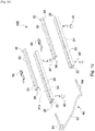
- a sliding device 100 according to the invention is schematically shown.
- the sliding device 100 comprises a pair of parallel tracks 10 each comprising a lower rail 20, intended to be attached to the vehicle floor (for instance by threaded fasteners 40), and an upper rail 30, intended to be attached to the frame of a vehicle seat.
- each upper rail 30 is constrained to the respective lower rail 20, but it can slide relative thereto.
- the sliding device 100 further comprises a releasing member 60, arranged for driving the latches 50 to an unlocking position, in which they allow the upper rails to slide relative to the lower rails.
- the releasing member is made as a "U"-shaped releasing handle 60 comprising a middle gripping portion 62 and two substantially parallel arms 64, the end portions of which are arranged to drive the respective latches 50 to their unlocking position.
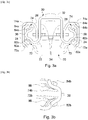
- each lower rail 20 has a cross-section having the shape of an upwardly oriented "U" and comprises a lower wall 22 and a pair of parallel, upwardly oriented vertical walls 24, ending with respective inwardly and downwardly bent flanges 26; namely, each flange 26 of the lower rail 20 has a first, inwardly oriented portion 26a departing from the upper end of the respective upwardly oriented vertical wall 24, and a second, downwardly oriented portion 26b extending from said first, inwardly oriented portion 26a.
- each upper rail 30 has a cross-section having the shape of a downwardly oriented "U” and comprises an upper wall 32 and a pair of parallel, downwardly oriented vertical walls 34, ending with respective outwardly and upwardly bent flanges 36.
- the outwardly and upwardly bent flanges 36 of the upper rail 30 may become engaged under the inwardly and downwardly bent flanges 26 of the respective lower rail 20 thus constraining said upper rail to said lower rail, while allowing a sliding movement of said upper rail relative to said lower rail.
- a lower ball guide 72 and an upper ball guide 74 are formed by said lower and upper rails as follows:
- the outwardly and upwardly bent flange 36 of the upper rail 30 is shaped in such a way that said second lower ball guide portion 72b comprises a straight section 76a and a curved section 76b and said second upper ball guide portion 74b also comprises a straight section 78a and a curved section 78b.
- the balls 70 in the lower ball guide 72 contact the second lower ball guide portion 72b at the straight section 76a, only, while they are spaced apart from the curved section 76b of said second lower ball guide portion 72b.
- the balls in the upper ball guide 74 contact the second upper ball guide portion 74b at the straight section 78a only, while they are spaced apart from the curved section 78b of said second upper ball guide portion 74b.
- the contact area between the second lower / upper ball guide portions 72b, 74b and the respective balls 70 is minimized, which allows to reduce friction and, as a result, minimize efforts during sliding movements of the upper rail 30 relative to the lower rail 20.
- the upper and lower rails are pressed against each other and slightly elastically deformed, so that the curved section 76b of the second lower ball guide portion 72b comes into contact with the balls received in the lower ball guide 72 and the curved section 78b of the second upper ball guide portion 74b comes into contact with the balls received in the upper ball guide 74.
- the straight section 76a of the second lower ball guide portion 72b is above the curved section 76b of said second lower ball guide portion and the straight section 78a of the second upper ball guide portion 74b is below the curved section 78b of said second upper ball guide portion.
- the curvature radius of the first lower ball guide portion 72a is substantially equal to the radius of the balls 70 received in the lower ball guide 72 and the curvature radius of the curved section 76b of the second lower ball guide portion 72b is larger than the radius of said balls.
- the curvature radius of the first upper ball guide portion 74a is substantially equal to the radius of the balls 70 received in the upper ball guide 74 and the curvature radius of the curved section 78b of the second upper ball guide portion 74b is larger than the radius of said balls.
- the balls received in the lower ball guide 72 may have a radius different from the radius of the balls received in the upper ball guide 74, or - as an alternative - all the balls 70 may have the same radius.
- a second ball stopping element is provided by providing a tab 82b protruding from the upper rail wall at the second lower ball guide portion 72b towards the center of the lower ball guide 72 at selected locations along the longitudinal axis of said upper rail.
- one or more grooves 86 are carved into the upper rail wall at the second lower ball guide portion 72b at selected locations along the longitudinal axis of said upper rail and one or more tabs 82b are fitted into said grooves so as to protrude towards the center of the lower ball guide 72.
- a second ball stopping element is provided by providing a tab 84b protruding from the upper rail wall at the second upper ball guide portion 74b towards the center of the upper ball guide 74 at selected locations along the longitudinal axis of said upper rail.
- one or more grooves 88 are carved into the upper rail wall at the second upper ball guide portion 74b at selected locations along the longitudinal axis of said upper rail and one or more tabs 84b are fitted into said grooves so as to protrude towards the center of the upper ball guide 74.
- the ball stopping elements 82a, 82b, 84a,84b of the sliding device according to the invention have a simple construction, they can be made by an easy and inexpensive process and demanding tolerances are not required.
- each upper rail 30 is constrained to the respective lower rail 20, but it can slide relative thereto.
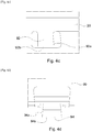
- such sliding movement has to be limited in the longitudinal direction in order to prevent the upper rail from disengaging from the respective lower rail.
- a first end stop 92 is provided by cutting and bending a first flap 92 from the wall of the lower rail and a second end stop 94 is provided by cutting and bending a second flap 94 from the wall of the upper rail, the first and second end stops 92, 94 being arranged so that they abut against each other and prevent further movement of the upper rail relative to the respective lower rail.
- the first and second end stops are shaped as flared flaps 92, 94, i.e. flaps having a trapezoidal shape, with slightly inclined cooperating sides 92a, 94a and with the longer bases 92b, 94b far from the rail wall from which they depart.
- the flared shape of the first and second end stops 92, 94 advantageously ensures a positive engagement between said first and second end stops, thus providing a very strong engagement.
- Figures 5a and 5b show the reinforcement block 110 which, in a per se known manner is fitted inside the downwardly oriented opening of the upper rail 30 (between the downwardly oriented vertical walls 34 of said upper rail) for preventing bowing and peeling of said upper rail during high crash loads condition and preventing seat collapse.
- the downwardly oriented vertical walls 34 of the upper rail 30 are correspondingly provided with one or more inwardly protruding lugs 112, 114 at selected location along the longitudinal axis of said upper rail.
- the facing lower lugs 112 of the vertical walls 34 of the upper rail 30 allow to easily assemble the reinforcement block 110 to the respective upper rail.
- the facing upper lugs 114 of the vertical walls 34 of the upper rail 30 allow to precisely set the position of said reinforcement block and resist possible transversal movements.
Landscapes
- Engineering & Computer Science (AREA)
- Aviation & Aerospace Engineering (AREA)
- Transportation (AREA)
- Mechanical Engineering (AREA)
- Seats For Vehicles (AREA)
Claims (10)
- Schiebevorrichtung (100) für einen Fahrzeugsitz, wobei die Schiebevorrichtung ein Paar parallele Schienen (10) aufweist, das jeweils eine untere Schiene (20) und eine obere Schiene (30), die verschiebbar an der unteren Schiene (20) befestigt ist, enthält, wobei jede untere Schiene (20) einen Querschnitt hat, der die Form eines nach oben gerichteten "U" hat und eine untere Wand (22) sowie ein Paar parallele, nach oben gerichtete vertikale Wände (24) aufweist, die in jeweiligen einwärts und nach unten gebogenen Flaschen (26) enden, wobei jede obere Schiene (30) einen Querschnitt hat, der die Form eines nach unten gerichteten "U" hat und eine obere Wand (32) sowie ein Paar parallele, nach unten gerichtete vertikale Wände (34) aufweist, die in jeweiligen nach außen und oben gebogenen Flanschen (36) enden, wobei die nach außen und oben gebogenen Flansche (36) der oberen Schiene (30) unter die nach innen und unten gebogene Flanschen (26) der unteren Schiene (20) greifen, wobei Kugeln (70) zwischen den unteren und oberen Schienen angeordnet sind, wobei auf jeder Seite der Schienen (20, 30) eine untere Kugelführung (72) und eine obere Kugelführung (74) für die Kugeln von der unteren und der oberen Schiene gebildet ist, wobei die untere Kugelführung (72) durch einen ersten unteren Kugelführungsabschnitt (72a), der von der unteren Schiene an der gebogenen Verbindung der unteren Wand (22) zu der jeweiligen nach oben gerichteten vertikalen Wand (24) gebildet ist, und durch einen zweiten Kugelführungsabschnitt (72b), der durch den nach außen und oben gebogenen Flansch (36) der oberen Schiene gebildet ist, definiert ist und die obere Schienenführung (74) durch einen unteren Kugelführungsabschnitt (74a), der von der unteren Schiene an der gebogenen Verbindung der nach oben orientierten vertikalen Wand (24) zu dem jeweiligen einwärts und nach unten gebogenen Flansch (26) gebildet ist, und durch einen zweiten oberen Kugelführungsabschnitt (74b), der durch den nach außen und oben gebogenen Flansch (36) der oberen Schiene gebildet ist, definiert ist, dadurch gekennzeichnet, dass der zweite untere Kugelführungsabschnitt (72b) einen geradlinigen Abschnitt (76a) und einen gekrümmten Abschnitt (76b) aufweist, wobei die Kugeln (70) in der unteren Kugelführung (72) im normalen Betrieb den zweiten unteren Kugelführungsabschnitt (72b) in seinem geradlinigen Bereich (76a) nur berühren, während sie von seinem gekrümmten Abschnitt (76b) entfernt sind, und dass der zweite obere Kugelführungsabschnitt (74b) einen geradlinigen Abschnitt (78a) und einen gekrümmten Abschnitt (78b) aufweist, wobei die Kugeln (70) in der oberen Kugelführung (74) im normalen Betrieb den zweiten oberen Kugelführungsabschnitt (74b) in seinem geradlinigen Abschnitt (78a) nur berühren, während sie von seinem gekrümmten Abschnitt (78b) entfernt sind.
- Schiebevorrichtung nach Anspruch 1, wobei der geradlinige Abschnitt (76a) des zweiten unteren Kugelführungsabschnitts (72b) oberhalb von dem gekrümmten Abschnitt (76b) des zweiten unteren Kugelführungsabschnitts ist und der geradlinige Abschnitt (78a) des zweiten oberen Kugelführungsabschnitts (74b) unterhalb von dem gekrümmten Abschnitt (78b) des zweiten oberen Kugelführungsabschnitts ist.
- Schiebevorrichtung nach Anspruch 1 oder 2, wobei der Krümmungsradius des ersten unteren Kugelführungsabschnitts (72a) im Wesentlichen mit dem Radius der Kugeln (70) übereinstimmt, die in der unteren Kugelführung (72) liegen, und der Krümmungsradius des gekrümmten Abschnitts (76b) des zweiten unteren Kugelführungsabschnitts (72b) größer als der Radius der Kugeln ist, und wobei der Krümmungsradius des ersten oberen Kugelführungsabschnitts (74a) im Wesentlichen mit dem Radius der Kugeln (70) übereinstimmt, die in der oberen Kugelführung (74) liegen, und der Krümmungsradius des gekrümmten Abschnitts (78b) des zweiten oberen Kugelführungsabschnitts (74b) größer als der Radius der Kugeln ist.
- Schiebevorrichtung nach einem der Ansprüche 1 bis 3, wobei Kugelanschlagelemente (82a, 82b, 84a, 84b) vorgesehen sind, um die Bewegung der Kugeln entlang der oberen und unteren Kugelführungen (72, 74) zu begrenzen.
- Schiebevorrichtung nach Anspruch 4, wobei ein erstes Kugelanschlagelement (82a) für jede untere Kugelführung durch Einwärtsbiegen der unteren Schienenwand an dem ersten unteren Kugelführungsabschnitt (72a) an ausgewählten Stelle(n) entlang der Längsachse der unteren Schiene geschaffen ist und/oder für jede obere Kugelführung ein erstes Kugelanschlagelement (84a) durch Einwärtsbiegen der unteren Schienenwand an dem ersten oberen Kugelführungsabschnitt (74a) an ausgewählten Stelle(n) entlang der Längsachse der unteren Schiene geschaffen ist.
- Schiebevorrichtung nach Anspruch 4 oder 5, wobei für jede untere Kugelführung ein zweites Kugelanschlagelement (82b) geschaffen ist, indem eine Lasche vorgesehen ist, die an dem zweiten unteren Kugelführungsabschnitt (72b) von der oberen Schienenwand zu dem Zentrum der unteren Kugelführung an ausgewählten Stelle(n) hin entlang der Längsachse der oberen Schiene absteht, und/oder für jede obere Kugelführung ein zweites Kugelanschlagelement (82b) geschaffen ist, indem eine Lasche vorgesehen ist, die an dem zweiten oberen Kugelführungsabschnitt (74b) von der oberen Schienenwand hin zu dem Zentrum der oberen Kugelführung an ausgewählten Stelle(n) entlang der Längsachse der oberen Schiene absteht.
- Schiebevorrichtung nach einem der Ansprüche 1 bis 6, wobei Endanschläge (92, 94) vorgesehen sind, um die Relativbewegung der oberen Schiene relativ zu der entsprechenden unteren Schiene (20) zu begrenzen.
- Schiebevorrichtung nach Anspruch 7, wobei auf jeder Seite der unteren und oberen Schienen ein erster Endanschlag gebildet ist, indem eine erste Lasche (92) aus der Wand der unteren Schiene ausgeschnitten und herausgebogen ist, und ein zweiter Endanschlag gebildet ist, indem eine zweite Lasche (94) aus der Wand der oberen Schiene ausgeschnitten und herausgebogen ist, wobei der erste und der zweite Endanschlag (92, 94) so angeordnet sind, dass sie aneinander anliegen und weitergehende Bewegung der oberen Schiene relativ zu der entsprechend unteren Schiene verhindern können.
- Schiebevorrichtung nach Anspruch 8, wobei die erste und die zweite Lasche als aufgebördelte Laschen (92, 94) geformt sind.
- Schiebevorrichtung nach einem der Ansprüche 1 bis 9, wobei ein Verstärkungsblock (110) zwischen die nach unten gerichteten vertikalen Wände (34) der oberen Schiene eingepasst ist und wobei die nach unten vertikalen Wände (34) der oberen Schiene dementsprechend an ausgewählten Stellen entlang der Längsachse der oberen Schiene mit einer oder mehreren nach innen ragenden Laschen (112, 114) versehen sind, um den Verstärkungsblock in die obere Schiene einzubauen.
Applications Claiming Priority (2)
| Application Number | Priority Date | Filing Date | Title |
|---|---|---|---|
| IT102019000000313A IT201900000313A1 (it) | 2019-01-09 | 2019-01-09 | Dispositivo di scorrimento per un sedile di veicolo con una configurazione migliorata delle rotaie |
| PCT/IB2019/059304 WO2020144504A1 (en) | 2019-01-09 | 2019-10-30 | Sliding device for a vehicle seat with an improved rail design |
Publications (2)
| Publication Number | Publication Date |
|---|---|
| EP3703973A1 EP3703973A1 (de) | 2020-09-09 |
| EP3703973B1 true EP3703973B1 (de) | 2021-01-13 |
Family
ID=65952014
Family Applications (1)
| Application Number | Title | Priority Date | Filing Date |
|---|---|---|---|
| EP19795677.4A Active EP3703973B1 (de) | 2019-01-09 | 2019-10-30 | Schiebevorrichtung für einen fahrzeugsitz mit verbesserter schienengestaltung |
Country Status (14)
| Country | Link |
|---|---|
| US (1) | US10994636B2 (de) |
| EP (1) | EP3703973B1 (de) |
| JP (1) | JP6857284B2 (de) |
| KR (1) | KR102225761B1 (de) |
| CN (1) | CN111670132B (de) |
| AR (1) | AR117039A1 (de) |
| CA (1) | CA3123339C (de) |
| ES (1) | ES2871414T3 (de) |
| IT (1) | IT201900000313A1 (de) |
| MA (1) | MA54001B1 (de) |
| MX (1) | MX2021008332A (de) |
| RU (1) | RU2768083C1 (de) |
| TW (1) | TWI717089B (de) |
| WO (1) | WO2020144504A1 (de) |
Families Citing this family (8)
| Publication number | Priority date | Publication date | Assignee | Title |
|---|---|---|---|---|
| IT201800005731A1 (it) | 2018-05-25 | 2019-11-25 | Dispositivo di scorrimento per un sedile di veicolo | |
| IT201800006570A1 (it) | 2018-06-21 | 2019-12-21 | Dispositivo di scorrimento per un sedile di veicolo provvisto di un sistema di bloccaggio migliorato | |
| IT201800006569A1 (it) | 2018-06-21 | 2019-12-21 | Dispositivo di scorrimento per un sedile di veicolo provvisto di un sistema di bloccaggio migliorato | |
| IT201800006650A1 (it) | 2018-06-26 | 2019-12-26 | Dispositivo di scorrimento per un sedile di veicolo provvisto di un sistema di bloccaggio migliorato | |
| IT201800007333A1 (it) | 2018-07-19 | 2020-01-19 | Dispositivo di scorrimento per un sedile di veicolo provvisto di un gruppo di rilascio migliorato | |
| WO2020049377A1 (en) | 2018-09-05 | 2020-03-12 | Martur Italy S.R.L. | Sliding device for a vehicle seat provided with an improved locking arrangement |
| DE102019104530B3 (de) * | 2019-02-22 | 2020-06-10 | Grammer Ag | Führungseinrichtung zum Führen einer Verstellbewegung eines Fahrzeugsitzes |
| KR102672939B1 (ko) * | 2022-06-10 | 2024-06-10 | 주식회사 다스 | 이동식 레일장치 |
Family Cites Families (33)
| Publication number | Priority date | Publication date | Assignee | Title |
|---|---|---|---|---|
| JPS6028614B2 (ja) * | 1977-05-23 | 1985-07-05 | 三菱電機株式会社 | 放電加工装置 |
| JP3400613B2 (ja) * | 1995-06-28 | 2003-04-28 | アイシン精機株式会社 | 車両用シートスライド装置 |
| FR2736311B1 (fr) | 1995-07-04 | 1997-09-05 | Faure Bertrand Equipements Sa | Glissiere verrouillable en position pour sieges de vehicules automobiles |
| FR2741124B1 (fr) * | 1995-11-14 | 1998-01-23 | Faure Bertrand Equipements Sa | Glissiere de siege de vehicule |
| FR2755653B1 (fr) | 1996-11-14 | 1999-01-08 | Faure Bertrand Equipements Sa | Glissiere pour siege de vehicule, et siege equipe d'une telle glissiere |
| FR2793453B1 (fr) * | 1999-05-10 | 2001-07-27 | Faure Bertrand Equipements Sa | Glissiere pour siege de vehicule |
| DE10039511A1 (de) | 2000-08-12 | 2002-02-28 | Keiper Gmbh & Co | Sitzschienenpaar für einen Fahrzeugsitz |
| DE10039510B4 (de) * | 2000-08-12 | 2004-07-29 | Keiper Gmbh & Co. Kg | Sitzschienenpaar für einen Fahrzeugsitz |
| JP3614098B2 (ja) * | 2000-09-25 | 2005-01-26 | ジョンソン コントロールズ オートモーティブ システムズ株式会社 | シートスライド装置 |
| FR2841191B1 (fr) * | 2002-06-25 | 2004-12-24 | Faurecia Sieges Automobile | Glissiere pour siege de vehicule et son procede de fabrication |
| US7314204B2 (en) | 2005-09-27 | 2008-01-01 | Kabushikigaisha Imasen Denki Seisakusho | Sliding rail system |
| JP5085900B2 (ja) * | 2006-08-15 | 2012-11-28 | シロキ工業株式会社 | シートトラック装置 |
| JP5239332B2 (ja) * | 2007-12-27 | 2013-07-17 | アイシン精機株式会社 | 車両用シートスライド装置 |
| JP5327002B2 (ja) * | 2009-11-05 | 2013-10-30 | アイシン精機株式会社 | 車両用シートスライド装置 |
| JP2012126181A (ja) * | 2010-12-13 | 2012-07-05 | Shiroki Corp | スライドレール装置 |
| JP2012126382A (ja) * | 2011-09-20 | 2012-07-05 | Shiroki Corp | スライドレール装置 |
| DE102011115948B3 (de) * | 2011-10-12 | 2013-01-24 | Keiper Gmbh & Co. Kg | Längseinstellbarer Fahrzeugsitz |
| DE102012201274A1 (de) * | 2012-01-30 | 2013-08-01 | Lear Corporation | Sitzschienenmechanismus |
| CN202608593U (zh) * | 2012-04-11 | 2012-12-19 | 浙江龙生汽车部件股份有限公司 | 用于汽车座椅的滑轨装置 |
| JP5962250B2 (ja) * | 2012-06-21 | 2016-08-03 | アイシン精機株式会社 | 車両用シートスライド装置 |
| JP5900288B2 (ja) | 2012-10-30 | 2016-04-06 | アイシン精機株式会社 | 車両用シートスライド装置 |
| JP6028614B2 (ja) | 2013-02-19 | 2016-11-16 | アイシン精機株式会社 | 車両用シートスライド装置 |
| DE102013208003B4 (de) * | 2013-04-09 | 2016-01-07 | Johnson Controls Components Gmbh & Co. Kg | Längseinsteller für einen Fahrzeugsitz und Fahrzeugsitz |
| JP6089975B2 (ja) * | 2013-05-30 | 2017-03-08 | アイシン精機株式会社 | 車両用シートスライド装置 |
| CN203920477U (zh) * | 2014-06-11 | 2014-11-05 | 上海延锋江森座椅有限公司 | 一种座椅滑轨组件 |
| DE102014211993B4 (de) * | 2014-06-23 | 2019-09-05 | Lear Corporation | Sitzschienenanordnung mit Lastaufnahmestrukturen und Fahrzeugsitzanordnung |
| JP6579779B2 (ja) * | 2015-04-06 | 2019-09-25 | シロキ工業株式会社 | シートトラックレール |
| DE102015219472B4 (de) | 2015-08-06 | 2021-07-22 | Adient Luxembourg Holding S.À R.L. | Längsverstellvorrichtung für einen Fahrzeugsitz, Schienenpaar und Fahrzeugsitz |
| JP6861491B2 (ja) | 2016-09-16 | 2021-04-21 | シロキ工業株式会社 | シートトラック |
| DE102016225818B4 (de) | 2016-09-21 | 2021-05-12 | Adient Luxembourg Holding S.À R.L. | Längseinsteller sowie Fahrzeugsitz |
| JP2018052399A (ja) * | 2016-09-30 | 2018-04-05 | 株式会社Tf−Metal | シートスライド装置 |
| JP6911393B2 (ja) | 2017-03-07 | 2021-07-28 | トヨタ紡織株式会社 | シート用スライド装置 |
| CN107878264B (zh) * | 2017-11-23 | 2023-10-13 | 湖北中航精机科技有限公司 | 用于汽车座椅滑轨组件的钢球装配结构 |
-
2019
- 2019-01-09 IT IT102019000000313A patent/IT201900000313A1/it unknown
- 2019-10-30 KR KR1020207010395A patent/KR102225761B1/ko active Active
- 2019-10-30 CA CA3123339A patent/CA3123339C/en active Active
- 2019-10-30 RU RU2021117152A patent/RU2768083C1/ru active
- 2019-10-30 EP EP19795677.4A patent/EP3703973B1/de active Active
- 2019-10-30 US US16/758,524 patent/US10994636B2/en active Active
- 2019-10-30 JP JP2020520256A patent/JP6857284B2/ja active Active
- 2019-10-30 MA MA54001A patent/MA54001B1/fr unknown
- 2019-10-30 CN CN201980005112.7A patent/CN111670132B/zh active Active
- 2019-10-30 MX MX2021008332A patent/MX2021008332A/es unknown
- 2019-10-30 ES ES19795677T patent/ES2871414T3/es active Active
- 2019-10-30 WO PCT/IB2019/059304 patent/WO2020144504A1/en not_active Ceased
- 2019-11-05 TW TW108140077A patent/TWI717089B/zh active
- 2019-11-08 AR ARP190103294A patent/AR117039A1/es active IP Right Grant
Non-Patent Citations (1)
| Title |
|---|
| None * |
Also Published As
| Publication number | Publication date |
|---|---|
| US20200391619A1 (en) | 2020-12-17 |
| TW202026181A (zh) | 2020-07-16 |
| KR20200088800A (ko) | 2020-07-23 |
| MX2021008332A (es) | 2021-08-05 |
| CA3123339A1 (en) | 2020-07-16 |
| CA3123339C (en) | 2022-01-25 |
| MA54001B1 (fr) | 2022-06-30 |
| AR117039A1 (es) | 2021-07-07 |
| TWI717089B (zh) | 2021-01-21 |
| WO2020144504A1 (en) | 2020-07-16 |
| CN111670132B (zh) | 2021-07-20 |
| US10994636B2 (en) | 2021-05-04 |
| EP3703973A1 (de) | 2020-09-09 |
| IT201900000313A1 (it) | 2020-07-09 |
| CN111670132A (zh) | 2020-09-15 |
| ES2871414T3 (es) | 2021-10-28 |
| RU2768083C1 (ru) | 2022-03-23 |
| KR102225761B1 (ko) | 2021-03-10 |
| JP2021505455A (ja) | 2021-02-18 |
| JP6857284B2 (ja) | 2021-04-14 |
| MA54001A1 (fr) | 2021-12-31 |
| BR112021012815A2 (pt) | 2021-11-03 |
Similar Documents
| Publication | Publication Date | Title |
|---|---|---|
| EP3703973B1 (de) | Schiebevorrichtung für einen fahrzeugsitz mit verbesserter schienengestaltung | |
| CN101670797B (zh) | 儿童安全座椅 | |
| KR101278209B1 (ko) | 좌석 슬라이드 레일 | |
| US8075039B2 (en) | System comprising a motor vehicle seat runner and body destined to be fixed thereto, and method for making same | |
| JP3949671B2 (ja) | 自動車用シートのランナー | |
| CN203844632U (zh) | 车辆用座椅滑动装置 | |
| US11571991B2 (en) | Sliding device for a vehicle seat | |
| US11999272B2 (en) | Child safety seat | |
| KR19980071347A (ko) | 자동차 좌석용 슬라이드 | |
| EP2281714A1 (de) | Einstellbare Kindersicherheitssitzanordnung | |
| GB2482410A (en) | Child safety seat | |
| JP2010264971A (ja) | 側突用樹脂衝撃吸収体の取付構造 | |
| CN112406646A (zh) | 儿童安全座椅 | |
| US11065987B2 (en) | Seat slide device for vehicle | |
| CN210310041U (zh) | 儿童安全座椅 | |
| JP2015116998A (ja) | 車両用シートのスライドレール装置 | |
| KR101551209B1 (ko) | 위치조절 스텝의 무단화가 가능한 슬라이드형 시트 트랙 | |
| BR112021012815B1 (pt) | Dispositivo deslizante para um assento de veículo | |
| JP7495079B2 (ja) | シートスライドアジャスタのロック機構及びシートスライドアジャスタ | |
| CN210652801U (zh) | 一种座椅靠背锁止装置 | |
| JP2026070501A (ja) | 調整装置及びキャリア | |
| JP2016199100A (ja) | スライドレール |
Legal Events
| Date | Code | Title | Description |
|---|---|---|---|
| STAA | Information on the status of an ep patent application or granted ep patent |
Free format text: STATUS: UNKNOWN |
|
| STAA | Information on the status of an ep patent application or granted ep patent |
Free format text: STATUS: THE INTERNATIONAL PUBLICATION HAS BEEN MADE |
|
| PUAI | Public reference made under article 153(3) epc to a published international application that has entered the european phase |
Free format text: ORIGINAL CODE: 0009012 |
|
| STAA | Information on the status of an ep patent application or granted ep patent |
Free format text: STATUS: REQUEST FOR EXAMINATION WAS MADE |
|
| 17P | Request for examination filed |
Effective date: 20200316 |
|
| AK | Designated contracting states |
Kind code of ref document: A1 Designated state(s): AL AT BE BG CH CY CZ DE DK EE ES FI FR GB GR HR HU IE IS IT LI LT LU LV MC MK MT NL NO PL PT RO RS SE SI SK SM TR |
|
| AX | Request for extension of the european patent |
Extension state: BA ME |
|
| GRAP | Despatch of communication of intention to grant a patent |
Free format text: ORIGINAL CODE: EPIDOSNIGR1 |
|
| STAA | Information on the status of an ep patent application or granted ep patent |
Free format text: STATUS: GRANT OF PATENT IS INTENDED |
|
| INTG | Intention to grant announced |
Effective date: 20201014 |
|
| RIN1 | Information on inventor provided before grant (corrected) |
Inventor name: UESTUENBERK, CAN Inventor name: KRPO, AZRA |
|
| GRAS | Grant fee paid |
Free format text: ORIGINAL CODE: EPIDOSNIGR3 |
|
| GRAA | (expected) grant |
Free format text: ORIGINAL CODE: 0009210 |
|
| STAA | Information on the status of an ep patent application or granted ep patent |
Free format text: STATUS: THE PATENT HAS BEEN GRANTED |
|
| AK | Designated contracting states |
Kind code of ref document: B1 Designated state(s): AL AT BE BG CH CY CZ DE DK EE ES FI FR GB GR HR HU IE IS IT LI LT LU LV MC MK MT NL NO PL PT RO RS SE SI SK SM TR |
|
| DAV | Request for validation of the european patent (deleted) | ||
| DAX | Request for extension of the european patent (deleted) | ||
| REG | Reference to a national code |
Ref country code: GB Ref legal event code: FG4D |
|
| REG | Reference to a national code |
Ref country code: CH Ref legal event code: EP |
|
| REG | Reference to a national code |
Ref country code: IE Ref legal event code: FG4D |
|
| REG | Reference to a national code |
Ref country code: DE Ref legal event code: R096 Ref document number: 602019002201 Country of ref document: DE |
|
| REG | Reference to a national code |
Ref country code: AT Ref legal event code: REF Ref document number: 1354315 Country of ref document: AT Kind code of ref document: T Effective date: 20210215 |
|
| REG | Reference to a national code |
Ref country code: AT Ref legal event code: MK05 Ref document number: 1354315 Country of ref document: AT Kind code of ref document: T Effective date: 20210113 |
|
| REG | Reference to a national code |
Ref country code: NL Ref legal event code: MP Effective date: 20210113 |
|
| REG | Reference to a national code |
Ref country code: LT Ref legal event code: MG9D |
|
| PG25 | Lapsed in a contracting state [announced via postgrant information from national office to epo] |
Ref country code: BG Free format text: LAPSE BECAUSE OF FAILURE TO SUBMIT A TRANSLATION OF THE DESCRIPTION OR TO PAY THE FEE WITHIN THE PRESCRIBED TIME-LIMIT Effective date: 20210413 Ref country code: HR Free format text: LAPSE BECAUSE OF FAILURE TO SUBMIT A TRANSLATION OF THE DESCRIPTION OR TO PAY THE FEE WITHIN THE PRESCRIBED TIME-LIMIT Effective date: 20210113 Ref country code: GR Free format text: LAPSE BECAUSE OF FAILURE TO SUBMIT A TRANSLATION OF THE DESCRIPTION OR TO PAY THE FEE WITHIN THE PRESCRIBED TIME-LIMIT Effective date: 20210414 Ref country code: FI Free format text: LAPSE BECAUSE OF FAILURE TO SUBMIT A TRANSLATION OF THE DESCRIPTION OR TO PAY THE FEE WITHIN THE PRESCRIBED TIME-LIMIT Effective date: 20210113 Ref country code: PT Free format text: LAPSE BECAUSE OF FAILURE TO SUBMIT A TRANSLATION OF THE DESCRIPTION OR TO PAY THE FEE WITHIN THE PRESCRIBED TIME-LIMIT Effective date: 20210513 Ref country code: NO Free format text: LAPSE BECAUSE OF FAILURE TO SUBMIT A TRANSLATION OF THE DESCRIPTION OR TO PAY THE FEE WITHIN THE PRESCRIBED TIME-LIMIT Effective date: 20210413 Ref country code: LT Free format text: LAPSE BECAUSE OF FAILURE TO SUBMIT A TRANSLATION OF THE DESCRIPTION OR TO PAY THE FEE WITHIN THE PRESCRIBED TIME-LIMIT Effective date: 20210113 |
|
| PG25 | Lapsed in a contracting state [announced via postgrant information from national office to epo] |
Ref country code: AT Free format text: LAPSE BECAUSE OF FAILURE TO SUBMIT A TRANSLATION OF THE DESCRIPTION OR TO PAY THE FEE WITHIN THE PRESCRIBED TIME-LIMIT Effective date: 20210113 Ref country code: PL Free format text: LAPSE BECAUSE OF FAILURE TO SUBMIT A TRANSLATION OF THE DESCRIPTION OR TO PAY THE FEE WITHIN THE PRESCRIBED TIME-LIMIT Effective date: 20210113 Ref country code: LV Free format text: LAPSE BECAUSE OF FAILURE TO SUBMIT A TRANSLATION OF THE DESCRIPTION OR TO PAY THE FEE WITHIN THE PRESCRIBED TIME-LIMIT Effective date: 20210113 Ref country code: RS Free format text: LAPSE BECAUSE OF FAILURE TO SUBMIT A TRANSLATION OF THE DESCRIPTION OR TO PAY THE FEE WITHIN THE PRESCRIBED TIME-LIMIT Effective date: 20210113 Ref country code: SE Free format text: LAPSE BECAUSE OF FAILURE TO SUBMIT A TRANSLATION OF THE DESCRIPTION OR TO PAY THE FEE WITHIN THE PRESCRIBED TIME-LIMIT Effective date: 20210113 |
|
| PG25 | Lapsed in a contracting state [announced via postgrant information from national office to epo] |
Ref country code: IS Free format text: LAPSE BECAUSE OF FAILURE TO SUBMIT A TRANSLATION OF THE DESCRIPTION OR TO PAY THE FEE WITHIN THE PRESCRIBED TIME-LIMIT Effective date: 20210513 |
|
| REG | Reference to a national code |
Ref country code: DE Ref legal event code: R097 Ref document number: 602019002201 Country of ref document: DE |
|
| REG | Reference to a national code |
Ref country code: ES Ref legal event code: FG2A Ref document number: 2871414 Country of ref document: ES Kind code of ref document: T3 Effective date: 20211028 |
|
| PG25 | Lapsed in a contracting state [announced via postgrant information from national office to epo] |
Ref country code: EE Free format text: LAPSE BECAUSE OF FAILURE TO SUBMIT A TRANSLATION OF THE DESCRIPTION OR TO PAY THE FEE WITHIN THE PRESCRIBED TIME-LIMIT Effective date: 20210113 Ref country code: CZ Free format text: LAPSE BECAUSE OF FAILURE TO SUBMIT A TRANSLATION OF THE DESCRIPTION OR TO PAY THE FEE WITHIN THE PRESCRIBED TIME-LIMIT Effective date: 20210113 Ref country code: SM Free format text: LAPSE BECAUSE OF FAILURE TO SUBMIT A TRANSLATION OF THE DESCRIPTION OR TO PAY THE FEE WITHIN THE PRESCRIBED TIME-LIMIT Effective date: 20210113 |
|
| PLBE | No opposition filed within time limit |
Free format text: ORIGINAL CODE: 0009261 |
|
| STAA | Information on the status of an ep patent application or granted ep patent |
Free format text: STATUS: NO OPPOSITION FILED WITHIN TIME LIMIT |
|
| PG25 | Lapsed in a contracting state [announced via postgrant information from national office to epo] |
Ref country code: DK Free format text: LAPSE BECAUSE OF FAILURE TO SUBMIT A TRANSLATION OF THE DESCRIPTION OR TO PAY THE FEE WITHIN THE PRESCRIBED TIME-LIMIT Effective date: 20210113 Ref country code: SK Free format text: LAPSE BECAUSE OF FAILURE TO SUBMIT A TRANSLATION OF THE DESCRIPTION OR TO PAY THE FEE WITHIN THE PRESCRIBED TIME-LIMIT Effective date: 20210113 Ref country code: RO Free format text: LAPSE BECAUSE OF FAILURE TO SUBMIT A TRANSLATION OF THE DESCRIPTION OR TO PAY THE FEE WITHIN THE PRESCRIBED TIME-LIMIT Effective date: 20210113 |
|
| 26N | No opposition filed |
Effective date: 20211014 |
|
| PG25 | Lapsed in a contracting state [announced via postgrant information from national office to epo] |
Ref country code: AL Free format text: LAPSE BECAUSE OF FAILURE TO SUBMIT A TRANSLATION OF THE DESCRIPTION OR TO PAY THE FEE WITHIN THE PRESCRIBED TIME-LIMIT Effective date: 20210113 |
|
| PG25 | Lapsed in a contracting state [announced via postgrant information from national office to epo] |
Ref country code: IS Free format text: LAPSE BECAUSE OF FAILURE TO SUBMIT A TRANSLATION OF THE DESCRIPTION OR TO PAY THE FEE WITHIN THE PRESCRIBED TIME-LIMIT Effective date: 20210513 |
|
| REG | Reference to a national code |
Ref country code: BE Ref legal event code: MM Effective date: 20211031 |
|
| PG25 | Lapsed in a contracting state [announced via postgrant information from national office to epo] |
Ref country code: MC Free format text: LAPSE BECAUSE OF FAILURE TO SUBMIT A TRANSLATION OF THE DESCRIPTION OR TO PAY THE FEE WITHIN THE PRESCRIBED TIME-LIMIT Effective date: 20210113 |
|
| PG25 | Lapsed in a contracting state [announced via postgrant information from national office to epo] |
Ref country code: LU Free format text: LAPSE BECAUSE OF NON-PAYMENT OF DUE FEES Effective date: 20211030 Ref country code: BE Free format text: LAPSE BECAUSE OF NON-PAYMENT OF DUE FEES Effective date: 20211031 |
|
| PG25 | Lapsed in a contracting state [announced via postgrant information from national office to epo] |
Ref country code: IE Free format text: LAPSE BECAUSE OF NON-PAYMENT OF DUE FEES Effective date: 20211030 |
|
| REG | Reference to a national code |
Ref country code: CH Ref legal event code: PL |
|
| PG25 | Lapsed in a contracting state [announced via postgrant information from national office to epo] |
Ref country code: NL Free format text: LAPSE BECAUSE OF NON-PAYMENT OF DUE FEES Effective date: 20210113 Ref country code: CY Free format text: LAPSE BECAUSE OF FAILURE TO SUBMIT A TRANSLATION OF THE DESCRIPTION OR TO PAY THE FEE WITHIN THE PRESCRIBED TIME-LIMIT Effective date: 20210113 |
|
| P01 | Opt-out of the competence of the unified patent court (upc) registered |
Effective date: 20230601 |
|
| PG25 | Lapsed in a contracting state [announced via postgrant information from national office to epo] |
Ref country code: LI Free format text: LAPSE BECAUSE OF NON-PAYMENT OF DUE FEES Effective date: 20221031 Ref country code: HU Free format text: LAPSE BECAUSE OF FAILURE TO SUBMIT A TRANSLATION OF THE DESCRIPTION OR TO PAY THE FEE WITHIN THE PRESCRIBED TIME-LIMIT; INVALID AB INITIO Effective date: 20191030 Ref country code: CH Free format text: LAPSE BECAUSE OF NON-PAYMENT OF DUE FEES Effective date: 20221031 |
|
| PG25 | Lapsed in a contracting state [announced via postgrant information from national office to epo] |
Ref country code: SI Free format text: LAPSE BECAUSE OF FAILURE TO SUBMIT A TRANSLATION OF THE DESCRIPTION OR TO PAY THE FEE WITHIN THE PRESCRIBED TIME-LIMIT Effective date: 20210113 |
|
| PG25 | Lapsed in a contracting state [announced via postgrant information from national office to epo] |
Ref country code: MK Free format text: LAPSE BECAUSE OF FAILURE TO SUBMIT A TRANSLATION OF THE DESCRIPTION OR TO PAY THE FEE WITHIN THE PRESCRIBED TIME-LIMIT Effective date: 20210113 |
|
| PG25 | Lapsed in a contracting state [announced via postgrant information from national office to epo] |
Ref country code: MT Free format text: LAPSE BECAUSE OF FAILURE TO SUBMIT A TRANSLATION OF THE DESCRIPTION OR TO PAY THE FEE WITHIN THE PRESCRIBED TIME-LIMIT Effective date: 20210113 |
|
| REG | Reference to a national code |
Ref country code: DE Ref legal event code: R081 Ref document number: 602019002201 Country of ref document: DE Owner name: MFI ITALY ENGINEERING S.R.L., IT Free format text: FORMER OWNER: MARTUR ITALY S.R.L., MILANO, IT |
|
| REG | Reference to a national code |
Ref country code: GB Ref legal event code: 732E Free format text: REGISTERED BETWEEN 20250619 AND 20250625 |
|
| REG | Reference to a national code |
Ref country code: ES Ref legal event code: PC2A Owner name: MFI ITALY ENGINEERING S.R.L. Effective date: 20251112 |
|
| PGFP | Annual fee paid to national office [announced via postgrant information from national office to epo] |
Ref country code: DE Payment date: 20251021 Year of fee payment: 7 |
|
| PGFP | Annual fee paid to national office [announced via postgrant information from national office to epo] |
Ref country code: GB Payment date: 20251023 Year of fee payment: 7 |
|
| PGFP | Annual fee paid to national office [announced via postgrant information from national office to epo] |
Ref country code: IT Payment date: 20251023 Year of fee payment: 7 |
|
| PGFP | Annual fee paid to national office [announced via postgrant information from national office to epo] |
Ref country code: FR Payment date: 20251029 Year of fee payment: 7 |
|
| PGFP | Annual fee paid to national office [announced via postgrant information from national office to epo] |
Ref country code: TR Payment date: 20251024 Year of fee payment: 7 |
|
| PGFP | Annual fee paid to national office [announced via postgrant information from national office to epo] |
Ref country code: ES Payment date: 20260127 Year of fee payment: 7 |