EP3702080B1 - Bandsäge - Google Patents
Bandsäge Download PDFInfo
- Publication number
- EP3702080B1 EP3702080B1 EP20159763.0A EP20159763A EP3702080B1 EP 3702080 B1 EP3702080 B1 EP 3702080B1 EP 20159763 A EP20159763 A EP 20159763A EP 3702080 B1 EP3702080 B1 EP 3702080B1
- Authority
- EP
- European Patent Office
- Prior art keywords
- drive wheel
- band saw
- motor
- reamer attachment
- wheel assembly
- Prior art date
- Legal status (The legal status is an assumption and is not a legal conclusion. Google has not performed a legal analysis and makes no representation as to the accuracy of the status listed.)
- Active
Links
Images




Classifications
-
- B—PERFORMING OPERATIONS; TRANSPORTING
- B23—MACHINE TOOLS; METAL-WORKING NOT OTHERWISE PROVIDED FOR
- B23D—PLANING; SLOTTING; SHEARING; BROACHING; SAWING; FILING; SCRAPING; LIKE OPERATIONS FOR WORKING METAL BY REMOVING MATERIAL, NOT OTHERWISE PROVIDED FOR
- B23D53/00—Machines or devices for sawing with strap saw-blades which are effectively endless in use, e.g. for contour cutting
- B23D53/12—Hand-held or hand-operated sawing devices working with strap saw blades
-
- B—PERFORMING OPERATIONS; TRANSPORTING
- B23—MACHINE TOOLS; METAL-WORKING NOT OTHERWISE PROVIDED FOR
- B23B—TURNING; BORING
- B23B5/00—Turning-machines or devices specially adapted for particular work; Accessories specially adapted therefor
- B23B5/16—Turning-machines or devices specially adapted for particular work; Accessories specially adapted therefor for bevelling, chamfering, or deburring the ends of bars or tubes
-
- B—PERFORMING OPERATIONS; TRANSPORTING
- B23—MACHINE TOOLS; METAL-WORKING NOT OTHERWISE PROVIDED FOR
- B23D—PLANING; SLOTTING; SHEARING; BROACHING; SAWING; FILING; SCRAPING; LIKE OPERATIONS FOR WORKING METAL BY REMOVING MATERIAL, NOT OTHERWISE PROVIDED FOR
- B23D55/00—Sawing machines or sawing devices working with strap saw blades, characterised only by constructional features of particular parts
- B23D55/06—Sawing machines or sawing devices working with strap saw blades, characterised only by constructional features of particular parts of drives for strap saw blades; of wheel mountings
-
- B—PERFORMING OPERATIONS; TRANSPORTING
- B23—MACHINE TOOLS; METAL-WORKING NOT OTHERWISE PROVIDED FOR
- B23D—PLANING; SLOTTING; SHEARING; BROACHING; SAWING; FILING; SCRAPING; LIKE OPERATIONS FOR WORKING METAL BY REMOVING MATERIAL, NOT OTHERWISE PROVIDED FOR
- B23D55/00—Sawing machines or sawing devices working with strap saw blades, characterised only by constructional features of particular parts
- B23D55/06—Sawing machines or sawing devices working with strap saw blades, characterised only by constructional features of particular parts of drives for strap saw blades; of wheel mountings
- B23D55/065—Sawing machines or sawing devices working with strap saw blades, characterised only by constructional features of particular parts of drives for strap saw blades; of wheel mountings of wheels
Definitions
- the present invention relates to a handheld band saw as per the preamble of appended claim 1.
- a handheld band saw is known from JP2004345042 .
- Handheld band saws are used to cut a variety of workpieces, such as pipes, rods, studs, and blocks.
- a cordless, compact band saw allows for cutting operations in tight spaces or awkward angles for plumbing, electrical, remodeling, and HVAC applications.
- the invention provides a handheld band saw includes a housing, a handle coupled to the housing and configured to be grasped by a user during a cutting operation, a motor supported by the housing, and a drive wheel assembly rotationally driven by the motor.
- the drive wheel assembly is at least partially disposed within the housing.
- the band saw further includes a saw blade driven by the drive wheel assembly. The saw blade is configured to cut a workpiece during the cutting operation.
- the band saw further includes a pipe reamer attachment coupled to the drive wheel assembly. The pipe reamer attachment is configured to deburr the workpiece after completion of the cutting operation.
- the handheld band saw may further comprise a battery removably coupled to the handle, wherein the battery, when coupled to the handle, may be configured to provide power to the motor.
- the handheld band saw may further comprise a trigger disposed adjacent a gripping portion of the handle, wherein power from the battery may be supplied to the motor when the trigger is actuated.
- the motor may define a rotational axis, and the pipe reamer attachment may be rotationally driven by the motor about the rotational axis.
- the pipe reamer attachment may be removably coupled to the drive wheel assembly.
- the handheld band saw may further comprise a quick disconnect coupling that couples the pipe reamer attachment to the drive wheel assembly.
- the pipe reamer attachment may be integrally formed with at least one component of the drive wheel assembly to form a single piece.
- the drive wheel assembly may include a drive wheel driven by the motor and a driven wheel driven by the drive wheel via the saw blade, and the pipe reamer attachment may be disposed on the drive wheel.
- the pipe reamer attachment may include an annular shroud and a blade for engaging the workpiece, and the blade may be disposed within the annular shroud.
- the housing may include a deck and a guard coupled to the deck that cooperatively surround the saw blade in a shielded position, and the deck and guard may define a cut zone through which the saw blade passes in an exposed position to engage a workpiece.
- FIG. 1 illustrates a band saw 10 including a frame or housing 14 supporting a motor 18 and a gear box 22 ( FIG. 7 ).
- the motor 18 is configured as a DC brushless motor
- the band saw 10 includes a removable, rechargeable battery 26 for supplying power to the band saw 10.
- the motor 18 is drivingly connected to a drive assembly 30 through a gear box 22.
- the motor 18, the drive assembly 30, and the gear box 22 are supported by the housing 14.
- the drive assembly 30 may include any of a number of bearing arrangements and different gear train arrangements configured to provide a low-speed, high-torque output from the high-speed, low-torque input provided by the motor 18.
- the motor 18 and the drive assembly 30 are operable to drive a continuous band saw blade 34 to cut a workpiece ( FIG. 1 ).
- the housing 14 includes a main handle 38 with a trigger 42 to provide power to the band saw 10.
- the trigger 42 is disposed adjacent a gripping portion 44 of the handle 38 where a user grasps the band saw 10.
- the battery 26 is supported by the main handle 38 and is an 18-volt power tool battery 26. In other embodiments, the battery 26 may be supported on the housing 14.
- the trigger 42 is operable to control operation of the motor 18. Specifically, the battery 26 selectively supplies power to the motor 18 when the trigger 42 is actuated.
- the housing 14 of the band saw 10 also includes a deck 46 and a guard 50 coupled to the deck 46. A combination of the deck 46 and the guard 50 defines an opening or U-shaped cavity 54.
- the guard 50 includes a lip 52 that provides a recessed area 56 ( FIG. 7 ) in which the band saw blade 34 is positioned.
- the guard 50 substantially covers the band saw blade 34 when the blade 34 is in a shielded position (i.e., when the blade 26 is outside of a cut zone 58; FIG. 1 ).
- the U-shaped cavity 54 enables the band saw blade 34 to be in an exposed position (i.e., when the blade 26 passes through the cut zone 58; FIG. 1 ). In the exposed position, the blade 34 is fully exposed and unobstructed by the guard 50, allowing workpieces to be cut when entering the cut zone 58.
- the deck 46 includes a motor support portion 62 and a separate motor cover 66 that together enclose the motor 18.
- the band saw 10 further includes a drive wheel assembly 68 that supports and drives the saw blade 34.
- the drive wheel assembly 68 includes a drive wheel 70 that is directly driven by the motor 18 and a driven wheel 74 that is driven by the drive wheel 70 via the saw blade 34.
- the outer peripheral surface and the interior side of the drive wheel 70 and the driven wheel 74 are covered by the deck 46 and the guard 50.
- the drive wheel 70 rotates about a drive wheel axis 78 ( FIGS. 2-4 ) defined by a drive wheel spindle 82 ( FIG. 7 ).
- the drive wheel spindle 82 is rotationally supported by bearings 84 of the drive assembly 30.
- the drive wheel 70 is drivingly connected to the motor 18 via the gear box 22, the drive assembly 30, and the drive wheel spindle 82.
- the rotational axis 80 of the motor 18 is coaxially aligned with the drive wheel axis 78.
- the rotational axis 80 and the drive wheel axis 78 may be parallel or at some other oblique angle relative to each other.
- a tire 86 is coupled to the outer peripheral surface of each of the wheels 70, 74 (although only one of which is shown). Each tire 86 grips the saw blade 34 to drive motion thereof
- the band saw 10 further includes a pipe reamer attachment 90a that is coupled to and driven by the drive wheel assembly 68.
- the pipe reamer attachment 90a of the illustrated embodiment is coupled to the drive wheel 70, in other embodiments, the pipe reamer attachment 90a may alternatively be coupled to the driven wheel 74.
- the pipe reamer attachment 90a being coupled to the band saw 10, a user can both cut and ream (i.e., deburr) a pipe with a single tool.
- the pipe reamer attachment 90a is removably coupled to the drive wheel 70, while in other embodiments, the pipe reamer attachment 90a may be permanently coupled to or integrated as part of the drive wheel 70 ( FIG. 4 ).
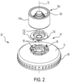
- the pipe reamer attachment 90a is coupled to the drive wheel 70 via a quick disconnect coupling 94, as shown in FIG. 2 .
- the quick disconnect coupling 94 includes spring detents 98 that mechanically interface with corresponding projections 102 to maintain the pipe reamer attachment 90a on the drive wheel 70. More specifically, when attaching the pipe reamer attachment 90a to the drive wheel 70, the projections 102 slide along the spring detents 98 to temporarily deform (i.e., flex) the spring detents 98.
- the drive wheel 70 is driven, for example, in a clockwise direction, while the pipe reamer attachment 90a is coupled to the drive wheel 70 by rotating the pipe reamer attachment 90a, for example, in a counterclockwise direction so as to inhibit the pipe reamer attachment 90a from disconnecting from the drive wheel 70 during operation.
- the pipe reamer attachment 90a includes an annular shroud 104a that accommodates pipe ranging from 0.85cm (1/3 inches) in diameter to 2.54cm (1 inch) in diameter. In other embodiments, the pipe reamer attachment 90a may accommodate pipe having a different diameter.
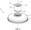
- FIG. 3 illustrates another embodiment of a pipe reamer attachment 90b that is coupled to the drive wheel 70 via a helical thread pattern 106.
- the drive wheel 70 includes a helical thread pattern 106 that engages with a corresponding thread pattern 106 on the piper reamer attachment 90b.
- the pipe reamer attachment 90b is rotatably coupled to the drive wheel 70 in an opposite direction of the direction of rotation of the drive wheel 70 to inhibit the pipe reamer attachment 90b from disconnecting from the drive wheel 70 during operation.
- the pipe reamer attachment 90b includes an annular shroud 104b that accommodates pipe ranging from 0.85cm (1/3 inches) in diameter to 2.54cm (1 inch) in diameter. In other embodiments, the pipe reamer attachment 90b may accommodate pipe having a different diameter.
- FIG. 4 illustrates yet another embodiment of a pipe reamer attachment 90c that is integrated as part of the drive wheel 70.
- the pipe reamer attachment 90c and the drive wheel 70 are formed as a single component that is directly coupled to the drive wheel spindle 82.
- the pipe reamer attachment 90c may also be recessed within the drive wheel 70, such that the pipe reamer attachment 90c does not extend or extends only slightly beyond the drive wheel 70, as shown in FIG. 4 .
- the pipe reamer attachment 90c includes an annular shroud 104c that accommodates pipe ranging from 0.85cm (1/3 inches) in diameter to 2.54cm (1 inch) in diameter. In other embodiments, the pipe reamer attachment 90c may accommodate pipe having a different diameter.
- Each pipe reamer attachment 90a, 90b, 90c includes a blade 108 for engaging and removing a burr formed on the end of a pipe after the blade 34 has cut the pipe.
- the blade 108 is disposed within the annular shroud 104a, 104b, 104c to prevent the blade 108 from being exposed from the exterior of the shroud 104a, 104b, 104c.
- the blade 108 of the illustrated embodiment is a multi-tiered blade, where each tier is capable of engaging a different sized pipe, such as pipes ranging from 0.85cm (1/3 inches) in diameter to 2.54cm (1 inch) in diameter. In other embodiments, the blade 108 may alternatively be three separate blades.
- the band saw 10 further includes a shoe 110 having a support surface 114 against which a workpiece is abutted during a cutting operation and a slot 116 through which the saw blade extends.
- the shoe 110 is adjacent the cut zone 58.
- the shoe 110 is adjustable along a shoe axis 118 that extends substantially parallel with the saw blade 34. By adjusting the shoe 110 along the shoe axis 118, the support surface 114 is moveable to support and accommodate pipes of varying diameters.
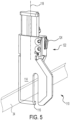
- the shoe 110 includes a slide mechanism 122 with an actuator 124 that, when depressed, allows a user to move the shoe 110 between a retracted position and an extended position along the shoe axis 118.
- the slide mechanism 122 maintains the shoe 110 in different predefined positions between the retracted and extended positions via a detent mechanism 125 ( FIG. 6 ).
- the detent mechanism 125 includes a tooth 126 that is actuated via the actuator 124, and a plurality of notches 128 that selectively receive the tooth 126 to maintain the shoe 110 in various predefined positions.
- the tooth 126 is in an extended position (as shown in FIG. 6 )
- the tooth is received in one of the notches 128 and inhibits the shoe 110 from moving along the shoe axis 118.
- the tooth 126 is in a retracted position, the tooth 126 is removed from one of the notches 128 thereby enabling the shoe 110 to move along the shoe axis 118.
- the detent mechanism 125 is designed in a cam-like manner such that the tooth 126 has a cam surface 127 shaped to permit the tooth 126 to be removed from the notch 128, without depressing the actuator 124, and moved to the retracted position when a sufficient upward force is exerted on the shoe 110 (from the frame of reference of FIGS. 5 and 6 ). In this case, the shoe 110 retracts to the retracted position in response to a sufficient force being exerted upon the shoe 110.
- An impact force proportionate to dropping the band saw 10 from a distance greater than approximately 5.08cm (two inches) above a ground surface is sufficient to cause the shoe 110 to retract to the retracted position when the impact force is exerted on the shoe 110.
- the resulting impact force exerted upon the shoe 110 overcomes the biasing force of the detent mechanism 125, allowing the shoe 110 to retract via the slide mechanism 122.
- the band saw 10 is dropped from a distance less than approximately 5.08cm (two inches) above a ground surface, the shoe 110 remains in position without retracting to the retracted position because the impact force exerted on the shoe 110 is not sufficient to overcome the biasing force of the detent mechanism 125.
- the slide mechanism 122 is designed to avoid causing damage to the shoe 110 when the band saw 10 is inadvertently dropped.
- the drive wheel 70 further includes a recess 130 on the interior side adjacent the motor 18.
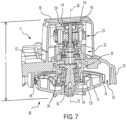
- the recess 130 accommodates a portion of the drive assembly 30, as shown in FIG. 7 .
- a top rotor bearing 134 is accommodated within a recess 138 of a motor fan 142, as shown in FIGS. 7-9 , and mounted within a corresponding pocket 144 in the motor cover 66 ( FIG. 7 ).
- the motor cover 66 and the motor fan 142 are spaced apart just enough to avoid mechanical interference, but the gap therebetween is otherwise negligible.
- the purpose of the recess 130 and the recess 138 is to consolidate the configuration of the motor 18, the gearbox 22, and the drive assembly 30 as much as possible so the motor cover 66 protrudes from the deck 46 as little as possible.
- the band saw 10 is more ergonomic and reduces torque exerted on a user during a cutting and reaming operation.
- the overall length L is between 5.08cm (2 inches) and 7.62cm (3 inches).
- the overall length is no more than 6.35cm (2.5 inches).
Landscapes
- Engineering & Computer Science (AREA)
- Mechanical Engineering (AREA)
- Sawing (AREA)
Claims (10)
- Handbandsäge (10), umfassend:ein Gehäuse (14);einen Griff (38), der mit dem Gehäuse gekoppelt und konfiguriert ist, um während eines Schneidvorgangs durch einen Benutzer ergriffen zu werden;einen Motor (18), der durch das Gehäuse getragen wird;eine Antriebsradanordnung (68), die durch den Motor rotierend angetrieben wird, wobei die Antriebsradanordnung mindestens teilweise innerhalb des Gehäuses eingerichtet ist;ein Sägeblatt (34), das durch die Antriebsradanordnung angetrieben wird und konfiguriert ist, um während des Schneidvorgangs ein Werkstück zu schneiden; und gekennzeichnet durcheinen Rohrreibahlenaufsatz (90a, 90b, 90c), der mit der Antriebsradanordnung gekoppelt ist, wobei der Rohrreibahlenaufsatz konfiguriert ist, um das Werkstück nach Abschluss des Schneidvorgangs zu entgraten.
- Handbandsäge (10) nach Anspruch 1, ferner umfassend eine Batterie (26), die mit dem Griff (38) abnehmbar gekoppelt ist, wobei die Batterie, wenn sie mit dem Griff gekoppelt ist, konfiguriert ist, um den Motor (18) mit Strom zu versorgen.
- Handbandsäge (10) nach Anspruch 2, die Handbandsäge ferner umfassend einen Auslöser (42), der angrenzend an einem Griffabschnitt (44) des Handgriffs (38) eingerichtet ist, wobei dem Motor (18) Strom von der Batterie (26) zugeführt wird, wenn der Auslöser betätigt wird.
- Handbandsäge (10) nach einem der vorstehenden Ansprüche, wobei der Motor (18) eine Rotationsachse (80) definiert und wobei der Rohrreibahlenaufsatz (90a, 90b, 90c) durch den Motor um die Rotationsachse rotierend angetrieben wird.
- Handbandsäge (10) nach einem der vorstehenden Ansprüche, wobei der Rohrreibahlenaufsatz (90a, 90b, 90c) mit der Antriebsradanordnung (68) abnehmbar gekoppelt ist.
- Handbandsäge (10) nach Anspruch 5, die Handbandsäge ferner umfassend eine Schnelltrennkopplung (94), die den Rohrreibahlenaufsatz (90a, 90b, 90c) mit der Antriebsradanordnung (68) koppelt.
- Handbandsäge (10) nach einem der vorstehenden Ansprüche, wobei der Rohrreibahlenaufsatz (90a, 90b, 90c) mit mindestens einer Komponente der Antriebsradanordnung (68) einstückig ausgebildet ist, um ein einzelnes Stück auszubilden.
- Handbandsäge (10) nach einem der vorstehenden Ansprüche, wobei die Antriebsradanordnung (68) ein Antriebsrad (70), das durch den Motor (18) angetrieben wird, und ein angetriebenes Rad (74), das durch das Antriebsrad über das Sägeblatt (34) angetrieben wird, einschließt, und wobei der Rohrreibahlenaufsatz (90a, 90b, 90c) an dem Antriebsrad eingerichtet ist.
- Handbandsäge (10) nach einem der vorstehenden Ansprüche, wobei der Rohrreibahlenaufsatz (90a, 90b, 90c) eine ringförmige Ummantelung (104a, 104b, 104c) und ein Sägeblatt (108) zum Eingreifen in das Werkstück einschließt, und wobei das Sägeblatt innerhalb der ringförmigen Ummantelung eingerichtet ist.
- Handbandsäge (10) nach einem der vorstehenden Ansprüche, wobei das Gehäuse (14) eine Deckplatte (46) und eine Schutzvorrichtung (50) einschließt, die mit der Deckplatte gekoppelt ist, die das Sägeblatt (34) in einer abgeschirmten Position gemeinsam umgeben, und wobei die Deckplatte und die Schutzvorrichtung eine Schnittzone (58) definieren, durch die das Sägeblatt (34) in einer freiliegenden Position hindurchgeht, um in ein Werkstück einzugreifen.
Priority Applications (1)
| Application Number | Priority Date | Filing Date | Title |
|---|---|---|---|
| EP24208804.5A EP4509252A1 (de) | 2019-03-01 | 2020-02-27 | Bandsäge |
Applications Claiming Priority (1)
| Application Number | Priority Date | Filing Date | Title |
|---|---|---|---|
| US201962812638P | 2019-03-01 | 2019-03-01 |
Related Child Applications (1)
| Application Number | Title | Priority Date | Filing Date |
|---|---|---|---|
| EP24208804.5A Division EP4509252A1 (de) | 2019-03-01 | 2020-02-27 | Bandsäge |
Publications (3)
| Publication Number | Publication Date |
|---|---|
| EP3702080A2 EP3702080A2 (de) | 2020-09-02 |
| EP3702080A3 EP3702080A3 (de) | 2020-12-16 |
| EP3702080B1 true EP3702080B1 (de) | 2024-10-30 |
Family
ID=69742745
Family Applications (2)
| Application Number | Title | Priority Date | Filing Date |
|---|---|---|---|
| EP20159763.0A Active EP3702080B1 (de) | 2019-03-01 | 2020-02-27 | Bandsäge |
| EP24208804.5A Pending EP4509252A1 (de) | 2019-03-01 | 2020-02-27 | Bandsäge |
Family Applications After (1)
| Application Number | Title | Priority Date | Filing Date |
|---|---|---|---|
| EP24208804.5A Pending EP4509252A1 (de) | 2019-03-01 | 2020-02-27 | Bandsäge |
Country Status (3)
| Country | Link |
|---|---|
| US (3) | US12070809B2 (de) |
| EP (2) | EP3702080B1 (de) |
| CN (1) | CN212443517U (de) |
Families Citing this family (5)
| Publication number | Priority date | Publication date | Assignee | Title |
|---|---|---|---|---|
| JP1655978S (de) * | 2019-09-12 | 2020-03-30 | ||
| WO2021083329A1 (zh) * | 2019-10-30 | 2021-05-06 | 南京德朔实业有限公司 | 手持式带锯 |
| CN114571000A (zh) * | 2020-12-02 | 2022-06-03 | 南京泉峰科技有限公司 | 带锯 |
| US20250018481A1 (en) * | 2023-07-14 | 2025-01-16 | Black & Decker Inc. | Bandsaw |
| US20250083239A1 (en) * | 2023-09-12 | 2025-03-13 | Milwaukee Electric Tool Corporation | Band saw |
Family Cites Families (95)
| Publication number | Priority date | Publication date | Assignee | Title |
|---|---|---|---|---|
| US1482954A (en) | 1921-12-10 | 1924-02-05 | United Electric Company | Adjustable caster |
| US1530682A (en) | 1923-04-03 | 1925-03-24 | Lyman Gustaf | Woodworking mechanism |
| US1955447A (en) * | 1931-01-22 | 1934-04-17 | Reed Mfg Co | Pipe reamer |
| US2330242A (en) * | 1941-08-25 | 1943-09-28 | Alvin L Romero | Reamer |
| US2596081A (en) | 1947-06-10 | 1952-05-06 | Elmer P Sacrey | Hand manipulated power band saw |
| US2591999A (en) | 1949-10-21 | 1952-04-08 | Sr Theophilus A Barham | Adjustable supporting leg |
| US2800933A (en) | 1956-06-08 | 1957-07-30 | Don L Michael | Rip guide for portable electric saws |
| US2916062A (en) | 1958-09-18 | 1959-12-08 | Dormeyer Corp | Splitter for portable electric saw |
| DE1152928B (de) * | 1961-08-10 | 1963-08-14 | Hauni Werke Koerber & Co Kg | Schneidvorrichtung in Strangzigarettenmaschinen |
| US3309050A (en) | 1965-05-06 | 1967-03-14 | Mitchell Mfg Company | Adjustable table legs |
| US3462171A (en) | 1967-01-18 | 1969-08-19 | Sol Mitty | Retractable wheel brackets for corrugated shipping cartons and shopping carts |
| US3495483A (en) * | 1967-03-29 | 1970-02-17 | Emerson Electric Co | Reversible pipe reamer |
| US3538964A (en) * | 1967-11-20 | 1970-11-10 | Rockwell Mfg Co | Motor driven table saw |
| US3553802A (en) | 1968-04-04 | 1971-01-12 | Techniservice Corp | Strand crimping |
| US3559514A (en) * | 1968-06-17 | 1971-02-02 | Russell Brownfield | Reamers for electrical line conduits, and the like |
| US3825355A (en) | 1973-07-02 | 1974-07-23 | Bell Telephone Labor Inc | Interlocking joint |
| CA1031945A (en) | 1974-08-06 | 1978-05-30 | Bernhard Bellmann | Milling cutter for preparing socket joints in complete prosthetic hip joint replacements |
| US4001937A (en) | 1975-04-28 | 1977-01-11 | Rockwell International Corporation | Portable power driven band saw |
| US4012158A (en) | 1975-09-15 | 1977-03-15 | Harper Henry J | Adjustable seat-back mechanism |
| US4036525A (en) | 1976-04-08 | 1977-07-19 | Gf Business Equipment, Inc. | Backrest adjustment mechanism |
| US4082475A (en) * | 1977-03-09 | 1978-04-04 | Frank A. Klaus | High speed reamer attachment for coaxial drive fastener gun |
| US4126340A (en) | 1977-06-02 | 1978-11-21 | The Eastern Company | Detent system for releasably retaining relatively movable members in predetermined positions |
| US4320680A (en) | 1980-03-03 | 1982-03-23 | Cruz Pantaleon S De | Fruit cutter |
| US4347634A (en) * | 1980-08-14 | 1982-09-07 | Sawan Anis S | Precision pipe cutter and reamer combination |
| US4930946A (en) * | 1988-10-19 | 1990-06-05 | Phillips Sr Douglas B | Chamfering reamer with trip shoulder |
| US4953295A (en) * | 1990-02-02 | 1990-09-04 | The United States Of America As Represented By The Secretary Of The Navy | Seawater hydraulic band saw |
| US5142825A (en) * | 1991-04-25 | 1992-09-01 | Floyd Kenneth R | Hand-held elongated stock material cutter |
| US5779724A (en) | 1992-12-04 | 1998-07-14 | Werner; Richard S. | Retractable surgical knife |
| US5720096A (en) | 1993-04-26 | 1998-02-24 | Black & Decker Inc. | Power tool with locking fence |
| US5509206A (en) * | 1993-10-27 | 1996-04-23 | Rowe; Jack L. | Portable or table mounted band saw utilizing dual cutting procedure of band saw blade |
| US5421091A (en) | 1994-02-23 | 1995-06-06 | S-B Power Tool Company | Adjustable guide shoe for reciprocating saw |
| JPH0834055A (ja) * | 1994-07-25 | 1996-02-06 | Shonan Gosei Jushi Seisakusho:Kk | 切削穿孔装置 |
| US5495672A (en) * | 1994-08-29 | 1996-03-05 | The Pullman Co. | Tube cutter |
| JPH08150513A (ja) * | 1994-11-24 | 1996-06-11 | Hirotoshi Kamibayashi | リーマ付き金切りノコ |
| US5755148A (en) | 1995-07-07 | 1998-05-26 | Black & Decker Inc. | Adjustable fence for a compound miter saw |
| JP2845823B2 (ja) * | 1996-07-19 | 1999-01-13 | 株式会社湘南合成樹脂製作所 | カッター |
| US5829142A (en) * | 1996-08-14 | 1998-11-03 | Rieser; Timothy John | Motorized tool having rotatably driven workpiece accessories |
| US5727322A (en) | 1996-12-31 | 1998-03-17 | Black & Decker Inc. | Adjustable shoe for a jig saw |
| US6393956B1 (en) | 1997-03-18 | 2002-05-28 | Interholtz Technik Gmbh | Device for cutting any width of wood or other materials |
| US6134997A (en) * | 1997-04-29 | 2000-10-24 | Rosanova; Rudolph P. | Tube cutter and method |
| CN1191907C (zh) | 1998-03-11 | 2005-03-09 | 布莱克和戴克公司 | 锯器 |
| US6234881B1 (en) * | 1998-08-06 | 2001-05-22 | Walter Ag | Grinding machine for forming chip-producing cutting tools |
| US6442848B1 (en) * | 1999-03-22 | 2002-09-03 | Ethan Dean | Coping saw |
| US6202311B1 (en) | 1999-07-30 | 2001-03-20 | Black & Decker Inc. | Circular saw with bevel angle adjustment mechanism |
| US6484409B2 (en) | 2000-04-21 | 2002-11-26 | Black & Decker Inc. | Pruner attachment apparatus for a power tool |
| JP4129111B2 (ja) | 2000-04-21 | 2008-08-06 | 日立工機株式会社 | 携帯用帯鋸機 |
| US6412376B1 (en) * | 2000-05-12 | 2002-07-02 | Joseph Borgia, Jr. | PVC pipe end smooth surfacer |
| US6857943B2 (en) * | 2000-06-28 | 2005-02-22 | Michael Kapgan | Burr removal apparatus |
| US6671969B2 (en) | 2001-12-18 | 2004-01-06 | Porter-Cable/Delta | Adjustable shoe for a reciprocating saw |
| US20060260141A1 (en) | 2001-12-18 | 2006-11-23 | Black & Decker, Inc. | Bearing for a reciprocating shaft of a reciprocating saw |
| US7779542B2 (en) * | 2002-04-18 | 2010-08-24 | Ormco Corporation | Method of manufacturing a dental instrument |
| US6829830B2 (en) | 2002-08-02 | 2004-12-14 | Black & Decker Inc. | Cut guide for portable saw |
| US7082689B2 (en) | 2002-10-11 | 2006-08-01 | Black & Decker Inc. | Keyless shoe lock for reciprocating saw |
| US7287454B2 (en) | 2003-02-19 | 2007-10-30 | Stout Tool Corp. | Hand-held band saw |
| JP4305058B2 (ja) | 2003-05-23 | 2009-07-29 | 日立工機株式会社 | 帯鋸機 |
| JP2004345042A (ja) * | 2003-05-23 | 2004-12-09 | Hitachi Koki Co Ltd | 帯のこ盤 |
| US8272133B2 (en) | 2003-07-03 | 2012-09-25 | Robert Bosch Gmbh | Circular saw having bevel and depth of cut detent system |
| GB2415660A (en) | 2004-06-29 | 2006-01-04 | Black & Decker Inc | Shoe assembly for power tool |
| US6896333B1 (en) | 2003-10-29 | 2005-05-24 | Leggett & Platt Ltd. | Height-adjustment mechanism for an armrest |
| US7926187B2 (en) | 2004-02-20 | 2011-04-19 | Milwaukee Electric Tool Corporation | Band saw |
| JP4468007B2 (ja) | 2004-02-25 | 2010-05-26 | 株式会社マキタ | レシプロソー |
| JP4554982B2 (ja) | 2004-05-10 | 2010-09-29 | 株式会社マキタ | 切断工具 |
| DE102004024280A1 (de) | 2004-05-15 | 2005-12-01 | Robert Bosch Gmbh | Universalsäge |
| US7434502B2 (en) | 2004-07-21 | 2008-10-14 | Husqvarna Outdoor Products Inc. | Bar knob with cam-operated locking mechanism |
| USD538618S1 (en) | 2004-11-01 | 2007-03-20 | Milwaukee Electric Tool Corporation | Portion of a power tool |
| TWM277546U (en) | 2005-05-13 | 2005-10-11 | Durq Machinery Corp | Platform saw having clamping mechanism |
| US7437824B2 (en) | 2005-06-27 | 2008-10-21 | Black & Decker Inc. | Adjustable shoe assembly for a reciprocating saw |
| US7540122B2 (en) * | 2005-07-07 | 2009-06-02 | Trudeau Walter H | Drywall repair tool and method |
| JP4549960B2 (ja) * | 2005-09-27 | 2010-09-22 | 株式会社マキタ | 携帯用バンドソー |
| ATE419086T1 (de) | 2006-03-18 | 2009-01-15 | Black & Decker Inc | Stichsäge mit vorrichtung zur späneabfuhr |
| CN2936514Y (zh) | 2006-08-17 | 2007-08-22 | 南京德朔实业有限公司 | 切割倾角可调的圆锯 |
| CN200963713Y (zh) | 2006-10-16 | 2007-10-24 | 南京德朔实业有限公司 | 带有可锁止支撑架的往复锯 |
| US20080148915A1 (en) | 2006-10-30 | 2008-06-26 | Black & Decker Inc. | Power tools |
| US8061043B2 (en) | 2006-11-15 | 2011-11-22 | Milwaukee Electric Tool Corporation | Power tool |
| US7651303B2 (en) * | 2007-03-06 | 2010-01-26 | Milwaukee Electric Tool Corporation | Conduit reamer tool element |
| US7857385B2 (en) | 2007-03-13 | 2010-12-28 | Cosco Management, Inc. | Compactible juvenile vehicle seat with forward-folding backrest and retractable armrests |
| DE102007000409A1 (de) | 2007-07-27 | 2009-01-29 | Hilti Aktiengesellschaft | Kreissägenständer |
| US8695224B2 (en) | 2007-09-13 | 2014-04-15 | Black & Decker Inc. | Saw with increased depth of cut |
| US8763258B2 (en) | 2008-01-31 | 2014-07-01 | Black & Decker Inc. | Portable band saw |
| US7950156B2 (en) | 2008-02-19 | 2011-05-31 | Black & Decker Inc. | Power tools |
| US20090241353A1 (en) | 2008-04-01 | 2009-10-01 | Scott William Ericson | Toolless Apparatus for Guide Bar for Chain Saw |
| US20090277315A1 (en) | 2008-05-08 | 2009-11-12 | Alek Ipatenco | Tile saw |
| WO2009149194A1 (en) | 2008-06-03 | 2009-12-10 | Milwaukee Electric Tool Corporation | Shoe accessory for a saw |
| US8418590B2 (en) | 2008-06-04 | 2013-04-16 | Black & Decker Inc. | Miter saws having locking assemblies for optimal positioning of cutting blades |
| US8549760B2 (en) | 2008-07-25 | 2013-10-08 | Milwaukee Electric Tool Corporation | Adjustable locking shoe |
| US20110119934A1 (en) | 2008-07-25 | 2011-05-26 | Bertsch Matthew T | Band saw |
| US8549759B2 (en) | 2008-07-25 | 2013-10-08 | Milwaukee Electric Tool Corporation | Adjustable shoe for a power tool |
| WO2011022366A1 (en) * | 2009-08-18 | 2011-02-24 | Emerson Electric Co. | Preparation tools for pipe ends and related methods |
| US8230605B2 (en) | 2009-09-15 | 2012-07-31 | Robert Bosch Gmbh | Shock absorbing, vibration isolating and jam protecting foot device for a reciprocating saw |
| EP3406381B1 (de) * | 2010-06-03 | 2021-09-29 | Milwaukee Electric Tool Corporation | Tragbare bandsäge mit schwenbarem klingenschutz |
| JP6377472B2 (ja) * | 2014-09-19 | 2018-08-22 | 株式会社マキタ | バンドソー |
| JP2016140939A (ja) | 2015-01-30 | 2016-08-08 | 日立工機株式会社 | バンドソー |
| JP7034850B2 (ja) | 2018-06-28 | 2022-03-14 | 株式会社マキタ | 携帯用バンドソー |
| JP6605087B2 (ja) * | 2018-07-24 | 2019-11-13 | 株式会社マキタ | バンドソー |
| US11351614B2 (en) * | 2019-06-14 | 2022-06-07 | Baldwin Products, LLC | Pipe reaming apparatus |
-
2020
- 2020-02-26 US US16/801,679 patent/US12070809B2/en active Active
- 2020-02-27 EP EP20159763.0A patent/EP3702080B1/de active Active
- 2020-02-27 EP EP24208804.5A patent/EP4509252A1/de active Pending
- 2020-02-28 CN CN202020226367.6U patent/CN212443517U/zh active Active
-
2023
- 2023-02-17 US US18/171,114 patent/US20230201936A1/en not_active Abandoned
-
2024
- 2024-07-18 US US18/777,151 patent/US20240367245A1/en active Pending
Also Published As
| Publication number | Publication date |
|---|---|
| US20200276660A1 (en) | 2020-09-03 |
| US20240367245A1 (en) | 2024-11-07 |
| US12070809B2 (en) | 2024-08-27 |
| US20230201936A1 (en) | 2023-06-29 |
| EP4509252A1 (de) | 2025-02-19 |
| EP3702080A3 (de) | 2020-12-16 |
| CN212443517U (zh) | 2021-02-02 |
| EP3702080A2 (de) | 2020-09-02 |
Similar Documents
| Publication | Publication Date | Title |
|---|---|---|
| US20240367245A1 (en) | Band saw | |
| US10710257B2 (en) | Power tool, such as a metal shears | |
| EP3388177B1 (de) | Handschneidwerkzeug | |
| EP2694260B1 (de) | Stichsäge | |
| EP2753446B1 (de) | Gehrungssäge mit doppelriementrieb | |
| US8857067B2 (en) | Saw assembly with floating bearing for worm drive and motor shaft | |
| US9434015B2 (en) | Saw assembly with bevel gear drivetrain | |
| US20080178718A1 (en) | Rotational power servo toolpost | |
| US20140103611A1 (en) | Bi-Directional Quick Change Tool-Less Lever and Wedge Actuated Collet Chuck, System and/or Method for Using the Same | |
| CA2886733C (en) | Saw assembly with bevel gear drivetrain | |
| KR102208476B1 (ko) | 그라인더 전환용 드릴 어댑터 | |
| US20250091244A1 (en) | Power tool | |
| AU2006338507A2 (en) | Rotary power tool | |
| CN201423567Y (zh) | 磨光、去漆、抛光三合一电动工具 | |
| CN117817767A (zh) | 一种切割偏移自提醒式电圆锯 | |
| CN211249528U (zh) | 一种手持式工具及其罩体 | |
| GB2495206A (en) | Power saw miter cutting guide | |
| WO2021088552A1 (zh) | 一种手持式工具及其罩体和操作方法 | |
| CN212762494U (zh) | 一种砂轮机 | |
| CN210282177U (zh) | 一种多功能电磨转换器 | |
| GB2395460A (en) | Electric hand tool machine with a handle parallel to a rotational plane of a rotatable tool | |
| CN2069765U (zh) | 多功能电钻 |
Legal Events
| Date | Code | Title | Description |
|---|---|---|---|
| PUAI | Public reference made under article 153(3) epc to a published international application that has entered the european phase |
Free format text: ORIGINAL CODE: 0009012 |
|
| STAA | Information on the status of an ep patent application or granted ep patent |
Free format text: STATUS: THE APPLICATION HAS BEEN PUBLISHED |
|
| AK | Designated contracting states |
Kind code of ref document: A2 Designated state(s): AL AT BE BG CH CY CZ DE DK EE ES FI FR GB GR HR HU IE IS IT LI LT LU LV MC MK MT NL NO PL PT RO RS SE SI SK SM TR |
|
| AX | Request for extension of the european patent |
Extension state: BA ME |
|
| PUAL | Search report despatched |
Free format text: ORIGINAL CODE: 0009013 |
|
| AK | Designated contracting states |
Kind code of ref document: A3 Designated state(s): AL AT BE BG CH CY CZ DE DK EE ES FI FR GB GR HR HU IE IS IT LI LT LU LV MC MK MT NL NO PL PT RO RS SE SI SK SM TR |
|
| AX | Request for extension of the european patent |
Extension state: BA ME |
|
| RIC1 | Information provided on ipc code assigned before grant |
Ipc: B23D 55/06 20060101ALI20201106BHEP Ipc: B23D 53/12 20060101AFI20201106BHEP Ipc: B23B 5/16 20060101ALI20201106BHEP Ipc: B23D 55/00 20060101ALI20201106BHEP Ipc: B24B 9/00 20060101ALI20201106BHEP |
|
| STAA | Information on the status of an ep patent application or granted ep patent |
Free format text: STATUS: REQUEST FOR EXAMINATION WAS MADE |
|
| 17P | Request for examination filed |
Effective date: 20210325 |
|
| RBV | Designated contracting states (corrected) |
Designated state(s): AL AT BE BG CH CY CZ DE DK EE ES FI FR GB GR HR HU IE IS IT LI LT LU LV MC MK MT NL NO PL PT RO RS SE SI SK SM TR |
|
| STAA | Information on the status of an ep patent application or granted ep patent |
Free format text: STATUS: EXAMINATION IS IN PROGRESS |
|
| 17Q | First examination report despatched |
Effective date: 20220624 |
|
| GRAP | Despatch of communication of intention to grant a patent |
Free format text: ORIGINAL CODE: EPIDOSNIGR1 |
|
| STAA | Information on the status of an ep patent application or granted ep patent |
Free format text: STATUS: GRANT OF PATENT IS INTENDED |
|
| INTG | Intention to grant announced |
Effective date: 20240529 |
|
| GRAS | Grant fee paid |
Free format text: ORIGINAL CODE: EPIDOSNIGR3 |
|
| GRAA | (expected) grant |
Free format text: ORIGINAL CODE: 0009210 |
|
| STAA | Information on the status of an ep patent application or granted ep patent |
Free format text: STATUS: THE PATENT HAS BEEN GRANTED |
|
| AK | Designated contracting states |
Kind code of ref document: B1 Designated state(s): AL AT BE BG CH CY CZ DE DK EE ES FI FR GB GR HR HU IE IS IT LI LT LU LV MC MK MT NL NO PL PT RO RS SE SI SK SM TR |
|
| REG | Reference to a national code |
Ref country code: GB Ref legal event code: FG4D |
|
| REG | Reference to a national code |
Ref country code: CH Ref legal event code: EP |
|
| REG | Reference to a national code |
Ref country code: DE Ref legal event code: R096 Ref document number: 602020040138 Country of ref document: DE |
|
| REG | Reference to a national code |
Ref country code: IE Ref legal event code: FG4D |
|
| REG | Reference to a national code |
Ref country code: LT Ref legal event code: MG9D |
|
| REG | Reference to a national code |
Ref country code: NL Ref legal event code: MP Effective date: 20241030 |
|
| PG25 | Lapsed in a contracting state [announced via postgrant information from national office to epo] |
Ref country code: IS Free format text: LAPSE BECAUSE OF FAILURE TO SUBMIT A TRANSLATION OF THE DESCRIPTION OR TO PAY THE FEE WITHIN THE PRESCRIBED TIME-LIMIT Effective date: 20250228 Ref country code: HR Free format text: LAPSE BECAUSE OF FAILURE TO SUBMIT A TRANSLATION OF THE DESCRIPTION OR TO PAY THE FEE WITHIN THE PRESCRIBED TIME-LIMIT Effective date: 20241030 Ref country code: PT Free format text: LAPSE BECAUSE OF FAILURE TO SUBMIT A TRANSLATION OF THE DESCRIPTION OR TO PAY THE FEE WITHIN THE PRESCRIBED TIME-LIMIT Effective date: 20250228 |
|
| PG25 | Lapsed in a contracting state [announced via postgrant information from national office to epo] |
Ref country code: FI Free format text: LAPSE BECAUSE OF FAILURE TO SUBMIT A TRANSLATION OF THE DESCRIPTION OR TO PAY THE FEE WITHIN THE PRESCRIBED TIME-LIMIT Effective date: 20241030 Ref country code: NL Free format text: LAPSE BECAUSE OF FAILURE TO SUBMIT A TRANSLATION OF THE DESCRIPTION OR TO PAY THE FEE WITHIN THE PRESCRIBED TIME-LIMIT Effective date: 20241030 |
|
| REG | Reference to a national code |
Ref country code: AT Ref legal event code: MK05 Ref document number: 1736433 Country of ref document: AT Kind code of ref document: T Effective date: 20241030 |
|
| PG25 | Lapsed in a contracting state [announced via postgrant information from national office to epo] |
Ref country code: BG Free format text: LAPSE BECAUSE OF FAILURE TO SUBMIT A TRANSLATION OF THE DESCRIPTION OR TO PAY THE FEE WITHIN THE PRESCRIBED TIME-LIMIT Effective date: 20241030 |
|
| PG25 | Lapsed in a contracting state [announced via postgrant information from national office to epo] |
Ref country code: ES Free format text: LAPSE BECAUSE OF FAILURE TO SUBMIT A TRANSLATION OF THE DESCRIPTION OR TO PAY THE FEE WITHIN THE PRESCRIBED TIME-LIMIT Effective date: 20241030 |
|
| PG25 | Lapsed in a contracting state [announced via postgrant information from national office to epo] |
Ref country code: NO Free format text: LAPSE BECAUSE OF FAILURE TO SUBMIT A TRANSLATION OF THE DESCRIPTION OR TO PAY THE FEE WITHIN THE PRESCRIBED TIME-LIMIT Effective date: 20250130 |
|
| PG25 | Lapsed in a contracting state [announced via postgrant information from national office to epo] |
Ref country code: LV Free format text: LAPSE BECAUSE OF FAILURE TO SUBMIT A TRANSLATION OF THE DESCRIPTION OR TO PAY THE FEE WITHIN THE PRESCRIBED TIME-LIMIT Effective date: 20241030 Ref country code: GR Free format text: LAPSE BECAUSE OF FAILURE TO SUBMIT A TRANSLATION OF THE DESCRIPTION OR TO PAY THE FEE WITHIN THE PRESCRIBED TIME-LIMIT Effective date: 20250131 Ref country code: AT Free format text: LAPSE BECAUSE OF FAILURE TO SUBMIT A TRANSLATION OF THE DESCRIPTION OR TO PAY THE FEE WITHIN THE PRESCRIBED TIME-LIMIT Effective date: 20241030 |
|
| PG25 | Lapsed in a contracting state [announced via postgrant information from national office to epo] |
Ref country code: PL Free format text: LAPSE BECAUSE OF FAILURE TO SUBMIT A TRANSLATION OF THE DESCRIPTION OR TO PAY THE FEE WITHIN THE PRESCRIBED TIME-LIMIT Effective date: 20241030 |
|
| PG25 | Lapsed in a contracting state [announced via postgrant information from national office to epo] |
Ref country code: RS Free format text: LAPSE BECAUSE OF FAILURE TO SUBMIT A TRANSLATION OF THE DESCRIPTION OR TO PAY THE FEE WITHIN THE PRESCRIBED TIME-LIMIT Effective date: 20250130 |
|
| PG25 | Lapsed in a contracting state [announced via postgrant information from national office to epo] |
Ref country code: SM Free format text: LAPSE BECAUSE OF FAILURE TO SUBMIT A TRANSLATION OF THE DESCRIPTION OR TO PAY THE FEE WITHIN THE PRESCRIBED TIME-LIMIT Effective date: 20241030 |
|
| PG25 | Lapsed in a contracting state [announced via postgrant information from national office to epo] |
Ref country code: DK Free format text: LAPSE BECAUSE OF FAILURE TO SUBMIT A TRANSLATION OF THE DESCRIPTION OR TO PAY THE FEE WITHIN THE PRESCRIBED TIME-LIMIT Effective date: 20241030 |
|
| PG25 | Lapsed in a contracting state [announced via postgrant information from national office to epo] |
Ref country code: EE Free format text: LAPSE BECAUSE OF FAILURE TO SUBMIT A TRANSLATION OF THE DESCRIPTION OR TO PAY THE FEE WITHIN THE PRESCRIBED TIME-LIMIT Effective date: 20241030 |
|
| PG25 | Lapsed in a contracting state [announced via postgrant information from national office to epo] |
Ref country code: RO Free format text: LAPSE BECAUSE OF FAILURE TO SUBMIT A TRANSLATION OF THE DESCRIPTION OR TO PAY THE FEE WITHIN THE PRESCRIBED TIME-LIMIT Effective date: 20241030 |
|
| PG25 | Lapsed in a contracting state [announced via postgrant information from national office to epo] |
Ref country code: SK Free format text: LAPSE BECAUSE OF FAILURE TO SUBMIT A TRANSLATION OF THE DESCRIPTION OR TO PAY THE FEE WITHIN THE PRESCRIBED TIME-LIMIT Effective date: 20241030 |
|
| PG25 | Lapsed in a contracting state [announced via postgrant information from national office to epo] |
Ref country code: CZ Free format text: LAPSE BECAUSE OF FAILURE TO SUBMIT A TRANSLATION OF THE DESCRIPTION OR TO PAY THE FEE WITHIN THE PRESCRIBED TIME-LIMIT Effective date: 20241030 |
|
| PG25 | Lapsed in a contracting state [announced via postgrant information from national office to epo] |
Ref country code: IT Free format text: LAPSE BECAUSE OF FAILURE TO SUBMIT A TRANSLATION OF THE DESCRIPTION OR TO PAY THE FEE WITHIN THE PRESCRIBED TIME-LIMIT Effective date: 20241030 |
|
| REG | Reference to a national code |
Ref country code: DE Ref legal event code: R097 Ref document number: 602020040138 Country of ref document: DE |
|
| PLBE | No opposition filed within time limit |
Free format text: ORIGINAL CODE: 0009261 |
|
| STAA | Information on the status of an ep patent application or granted ep patent |
Free format text: STATUS: NO OPPOSITION FILED WITHIN TIME LIMIT |
|
| PG25 | Lapsed in a contracting state [announced via postgrant information from national office to epo] |
Ref country code: SE Free format text: LAPSE BECAUSE OF FAILURE TO SUBMIT A TRANSLATION OF THE DESCRIPTION OR TO PAY THE FEE WITHIN THE PRESCRIBED TIME-LIMIT Effective date: 20241030 |
|
| PG25 | Lapsed in a contracting state [announced via postgrant information from national office to epo] |
Ref country code: MC Free format text: LAPSE BECAUSE OF FAILURE TO SUBMIT A TRANSLATION OF THE DESCRIPTION OR TO PAY THE FEE WITHIN THE PRESCRIBED TIME-LIMIT Effective date: 20241030 |
|
| REG | Reference to a national code |
Ref country code: CH Ref legal event code: PL |
|
| 26N | No opposition filed |
Effective date: 20250731 |
|
| PG25 | Lapsed in a contracting state [announced via postgrant information from national office to epo] |
Ref country code: LU Free format text: LAPSE BECAUSE OF NON-PAYMENT OF DUE FEES Effective date: 20250227 |
|
| PG25 | Lapsed in a contracting state [announced via postgrant information from national office to epo] |
Ref country code: CH Free format text: LAPSE BECAUSE OF NON-PAYMENT OF DUE FEES Effective date: 20250228 |
|
| REG | Reference to a national code |
Ref country code: BE Ref legal event code: MM Effective date: 20250228 |
|
| PG25 | Lapsed in a contracting state [announced via postgrant information from national office to epo] |
Ref country code: FR Free format text: LAPSE BECAUSE OF NON-PAYMENT OF DUE FEES Effective date: 20250228 |
|
| PG25 | Lapsed in a contracting state [announced via postgrant information from national office to epo] |
Ref country code: BE Free format text: LAPSE BECAUSE OF NON-PAYMENT OF DUE FEES Effective date: 20250228 |
|
| PG25 | Lapsed in a contracting state [announced via postgrant information from national office to epo] |
Ref country code: IE Free format text: LAPSE BECAUSE OF NON-PAYMENT OF DUE FEES Effective date: 20250227 |
|
| PGFP | Annual fee paid to national office [announced via postgrant information from national office to epo] |
Ref country code: GB Payment date: 20260227 Year of fee payment: 7 |
|
| PGFP | Annual fee paid to national office [announced via postgrant information from national office to epo] |
Ref country code: DE Payment date: 20260227 Year of fee payment: 7 |