EP3700853B1 - Auslegervorrichtung und fahrzeug, wie ein mobiler kran, mit der auslegervorrichtung - Google Patents
Auslegervorrichtung und fahrzeug, wie ein mobiler kran, mit der auslegervorrichtung Download PDFInfo
- Publication number
- EP3700853B1 EP3700853B1 EP18814706.0A EP18814706A EP3700853B1 EP 3700853 B1 EP3700853 B1 EP 3700853B1 EP 18814706 A EP18814706 A EP 18814706A EP 3700853 B1 EP3700853 B1 EP 3700853B1
- Authority
- EP
- European Patent Office
- Prior art keywords
- outrigger
- outrigger beam
- frame
- location
- extended position
- Prior art date
- Legal status (The legal status is an assumption and is not a legal conclusion. Google has not performed a legal analysis and makes no representation as to the accuracy of the status listed.)
- Active
Links
Images




Classifications
-
- B—PERFORMING OPERATIONS; TRANSPORTING
- B66—HOISTING; LIFTING; HAULING
- B66C—CRANES; LOAD-ENGAGING ELEMENTS OR DEVICES FOR CRANES, CAPSTANS, WINCHES, OR TACKLES
- B66C23/00—Cranes comprising essentially a beam, boom, or triangular structure acting as a cantilever and mounted for translatory of swinging movements in vertical or horizontal planes or a combination of such movements, e.g. jib-cranes, derricks, tower cranes
- B66C23/62—Constructional features or details
- B66C23/72—Counterweights or supports for balancing lifting couples
- B66C23/78—Supports, e.g. outriggers, for mobile cranes
-
- B—PERFORMING OPERATIONS; TRANSPORTING
- B66—HOISTING; LIFTING; HAULING
- B66C—CRANES; LOAD-ENGAGING ELEMENTS OR DEVICES FOR CRANES, CAPSTANS, WINCHES, OR TACKLES
- B66C2700/00—Cranes
- B66C2700/03—Cranes with arms or jibs; Multiple cranes
- B66C2700/0321—Travelling cranes
- B66C2700/0357—Cranes on road or off-road vehicles, on trailers or towed vehicles; Cranes on wheels or crane-trucks
- B66C2700/0378—Construction details related to the travelling, to the supporting of the crane or to the blocking of the axles; Outriggers; Coupling of the travelling mechamism to the crane mechanism
Definitions
- the invention relates to an outrigger assembly comprising an outrigger frame and an outrigger beam movable in a horizontal extension direction with respect to the outrigger frame in between a retracted position and an extended position.
- the outrigger beam is located inside the outrigger frame in the retracted position and is extended from the outrigger frame in the extended position.
- the outrigger beam has a proximal end and a distal end with respect to the outrigger frame in the extended position of the outrigger beam.
- the outrigger assembly further comprises an outrigger support coupled to the distal end of the outrigger beam to allow supporting the outrigger assembly in a supporting position of the outrigger support on a supporting surface in the extended position of the outrigger beam.
- the invention further relates to any vehicle, such as a mobile crane, provided with such an outrigger assembly with horizontally extendable outrigger beams.
- the outrigger beams are extended from the outrigger frame and the vehicle, and the outrigger supports are lowered onto the ground at a location where a heavy load is to be handled.
- the extended outrigger beams provide a much higher stability to the mobile crane and higher loads can be handled with increasing width of the extended outrigger assembly.
- the width of the extended outrigger assembly is determined by the length of the outrigger beams, while the length of the outrigger beams is limited by the width of the vehicle in which the outrigger beams are housed in their retracted position.
- Present vehicles with outrigger assemblies, especially mobile cranes have reached the limit of the maximum width of the extended outrigger assembly that can be achieved. A further increased width, however, would increase stability or the maximum load or load moment (load at a certain radius) that can be handled.
- US 3,756,424 discloses a mobile crane having an outrigger assembly of which outrigger beams can be extended from an outrigger frame to provide an extended position of the outrigger beams and a supporting position of the outrigger assembly. In the supporting position, an end of the outrigger beam being supported on the ground induces a first torque that is balanced by a second torque provided by the outrigger beam extending over a certain length still within the outrigger frame of the outrigger assembly.
- the extension length of the outrigger beam from the outrigger frame is limited by the total length of the outrigger beam, which is limited by the width of the mobile crane, and the length of the outrigger beam remaining within the outrigger frame to induce the second torque. This document discloses the preamble of claim 1.
- an outrigger assembly for supporting a vehicle on a supporting surface, the outrigger assembly comprising
- the second and third locations are at the proximal end of the outrigger beam, optionally at the extreme end of the proximal end.
- the second and third locations are coinciding locations.
- outrigger beam is movable along the extension direction to a first semi-extended position in between the retracted position and the extended position
- fifth and sixth locations are coinciding locations.
- fourth and seventh locations are coinciding locations.
- outrigger beam is movable along the extension direction to a second semi-extended position in between the retracted position and the extended position
- the second semi-extended position is in between the retracted position and the first semi-extended position, and the third horizontal distance is smaller then the second horizontal distance.
- the outrigger frame comprises a movable cam that is movable into a first or a second recess, respectively, corresponding with the second and the third location or the fifth and sixth location, respectively, such as to allow the second vertical force and first horizontal force or to allow the fourth vertical force and the third horizontal force, respectively, to act on the outrigger beam in the extended position or the first semi-extended position, respectively, of the outrigger beam, optionally the movable cam being a rotatable cam, optionally the movable cam being operable by a cam actuator, optionally an actuation cylinder, optionally a pneumatic, hydraulic, electrical or manual controlled actuation cylinder, optionally the first or second recess being provided in an upper surface of the outrigger beam, which provides a very fast and secure locking of the outrigger beam and transfer of outward horizontal and downward vertical forces onto the outrigger beam.
- the outrigger frame comprises a movable cam that is movable into a first recesses corresponding with the second and the third location such as to allow the second vertical force and first horizontal force to act on the outrigger beam in the extended position of the outrigger beam, and movable into a second recesses corresponding with the fifth and the sixth location such as to allow the fourth vertical force and the third horizontal force to act on the outrigger beam in the first semi-extended position of the outrigger beam, optionally the movable cam being a rotatable cam, optionally the movable cam being operable by a cam actuator, optionally an actuation cylinder, optionally a pneumatic, hydraulic, electrical or manual controlled actuation cylinder, optionally the first and second recesses being provided in an upper surface of the outrigger beam, which also provides a very fast and secure locking of the outrigger beam and transfer of outward horizontal and downward vertical forces onto the outrigger beam.
- the outrigger assembly comprises a slider element having first and second ends, the first end cooperating with the outrigger beam and the second end cooperating with the outrigger frame to allow extending the outrigger beam from the outrigger frame and to allow the second horizontal force to act on the outrigger beam in the extended position of the outrigger beam, optionally the first end of the slider element being slidably coupled to the outrigger beam to allow moving of the slider element with respect to the outrigger beam, which provides for a secure transfer of horizontal inward forces onto the outrigger beam.
- the outrigger frame comprises a first stop
- the second end of the slider element is slidable with respect to the outrigger frame upon extension of the outrigger beam from the outrigger frame, and the second end cooperates with the first stop to allow the second horizontal force to act on the outrigger beam in the extended position of the outrigger beam.
- the first end of the slider element cooperates with the outrigger beam and the second end cooperates with the outrigger frame to allow extending the outrigger beam from the outrigger frame and to allow the fourth horizontal force to act on the outrigger beam in the first semi-extended position of the outrigger beam
- the outrigger frame comprises a second stop
- the second end of the slider element cooperates with the second stop to allow the fourth horizontal force to act on the outrigger beam in the first semi-extended position of the outrigger beam.
- the first end of the slider element is slidably coupled to the outrigger beam to allow moving of the slider element with respect to the outrigger beam in between a first slider element position, in which the second end of the slider element is held by the outrigger beam, and a second slider element position, in which the second end is allowed to slide with respect to the outrigger frame, which allows that the slider element is housed within the outrigger beam to not take additional with in the retracted position and to allow cooperation with multiple stops on the outrigger frame.
- the outrigger assembly comprises first and second outrigger beam actuators operable for moving the outrigger beam and the outrigger frame with respect to one another, and for moving the slider element and the outrigger beam with respect to one another.
- the outrigger assembly is configured such that the first outrigger beam actuator is operable to allow moving the outrigger beam together with the second outrigger beam actuator and the slider element with respect to the outrigger frame, and the second actuator is operable to allow moving the outrigger beam with respect to the slider element and the outrigger frame.
- the first outrigger beam actuator comprises a first outrigger actuation cylinder having a first cylinder part and a first piston part movable with respect to the first cylinder part and coupled to the outrigger frame
- the second outrigger beam actuator comprises a second outrigger actuation cylinder having a second cylinder part and a second piston part movable with respect to the second cylinder part and couple to the outrigger beam
- the first and second cylinder parts and the first end of the slider element fixedly coupled to one another.
- the invention provides for a vehicle comprising an outrigger assembly as referred to above.
- the vehicle is a mobile crane.
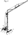
- Figure 2 shows a mobile crane in a position for operating the crane part.
- the outrigger beams 200 of the outrigger assemblies 10 are extended from the outrigger frame 100 that is part of the mobile crane, and the outrigger supports 300 are put in a supporting position on the supporting surface S, which may be road surface but can be any other generally horizontal surface.
- the outrigger support in the extended position provides stability to the crane so as to allow manipulating heavy loads.
- Figure 3 shows an outrigger assembly 10 according to the invention in more detail, with both outrigger beams 200 in the extended position and the outrigger supports 300 in the supporting position to support the outrigger beams on the supporting surface S.
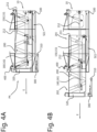
- Figures 4A to 4D show four stages to provide the outrigger beam 200 from the retracted position P4 of figure 4A , in which the outrigger beam is located within the outrigger frame 100, to the extended position P1 of figure 4D , in which the outrigger beam is fully extended from the outrigger frame.
- Figures 4B and 4C show intermediate positions of the outrigger beam 200 when moving along the horizontal extension direction E with respect to the outrigger frame 100 to the extended position of figure 4D .
- the outrigger beam is movable by operating the outrigger beam actuators 150, 160.
- the outrigger frame 100 comprises a movable cam 400 that is moved into the recess 211 provided in the top side surface of the outrigger beam in the fully extended position P1 shown in figure 4D .
- the cam is rotatable around a rotation axis 410 and can be rotated into and out of the recess 211 by a cam actuator 450 in the embodiment shown, but can also be moved in any other suitable manner into and out of the recess.
- the cam actuator 450 is a pneumatic controlled actuation cylinder in the embodiment shown, but can be any other suitable actuator such as, for instance, a hydraulic, manual or electrical controlled actuation cylinder.
- the outrigger beam is coupled to the outrigger frame through a slider element 500.
- the slider element in the form of a slider rod in the embodiment shown, has first and second ends 501, 502.
- the first end 501 of the slider element is held in an elongated slot 250 in the bottom region of the outrigger beam 200 by a projection of the slider element extending into the slot.
- the projection at the first end 501 of the slider element can slide along the slot between first and second slot ends 251, 252.
- Figure 4D of the extended position of the outrigger beam shows that the projection at the first end 501 of the slider element cooperates with the first slot end 251.
- a projection at the second end 502 of the slider element 500 cooperates with a first stop 111 in the bottom region of the outrigger frame 100.
- the outrigger support 300 is in its support position SP in the extended position P1 of the outrigger beam of figure 4D .
- the footplate 310 of the outrigger support has been lowered onto the supporting surface S by operating the actuation cylinder 320 of the outrigger support.
- Figures 4A to 4C show the footplate 310 of the outrigger support 300 in a raised position, which enables moving the outrigger beam in and out in between the retracted position P4 of figure 4A and the extended position P1 of figure 4D .
- the outrigger support 300 is coupled to the distal end 202 of the outrigger beam 200, while the outrigger beam at its proximal end 201 is coupled to the outrigger frame 100.
- the proximal and distal ends 201, 202 of the outrigger beam are defined with respect to the outrigger frame. In the extended position the distal end 202 of the outrigger beam 200 is positioned away from the outrigger frame, while the proximal end 201 is positioned close to the outrigger frame.
- the proximal and distal ends are each intended to indicate a zone at the ends and not to indicate the extreme end.
- the outrigger support 300 supports, together with the other outrigger support(s) coupled to the other outrigger beam(s), the weight of the vehicle, such as a mobile crane, of which it is a part, and its load and load moment.
- the outrigger support 300 causes a first vertical force Fv1 acting upwards at a first location L1 on the distal end 202 of the outrigger beam.
- the outrigger frame is supported on the outrigger beam through the cam 400 that is inserted into the first recess 211, which causes a second vertical force Fv2 acting downwards at a second location L2 on the outrigger beam.
- the second location L2 is separated from the first location L1 by a first horizontal distance Dh1 towards the proximal end of the outrigger beam.
- the second location L2 is near the extreme end of the proximal end of the outrigger beam.
- the forces may be distributed over a zone, but can be regarded to act on a single location on the frame and are shown as such in the figures.
- the first and second vertical forces Fv1, Fv2 separated by the first horizontal distance Dh1 cause a first torque to act on the outrigger beam.
- the first torque is balanced by a second torque determined by interaction between the outrigger frame and the outrigger beam through the cam 400 and slider element 500.
- the cam 400 coupled to the outrigger frame 100 and inserted into the first recess 211 causes a first horizontal force Fh1 acting outwards at a third location L3 on the outrigger beam.
- the second and third locations are the same, or virtually the same, as the second vertical force Fv2 and the first horizontal force Fh1 are both caused by the cam 400 acting on the outrigger beam.
- the second and third locations L2, L3 need not be the same.
- the slider element 500 by the projection at its first end 501 inserted into the slot 250 and cooperating with the first slot end 251 causes a second horizontal force Fh2 acting inwards at a fourth location L4 on the outrigger beam next to the first slot end 251.
- the horizontal forces are defined as outward or inward with respect to the outrigger frame, an outward direction being directed away from the outrigger frame and an inward direction being directed to the inside of the outrigger frame.
- the second horizontal force Fh2 can be exerted by the slider element since its second end 502 cooperates with the first stop 111 on the outrigger frame 100.
- the fourth location L4 is separated from the third location L3 by a first vertical distance Dv1 in a downward direction.
- the first and second horizontal forces Fh1, Fh2 separated by the first vertical distance Dv1 cause the second torque to act on the outrigger beam.
- the slider element 500 also causes a minor downward vertical force component acting on the outrigger beam, which is due to the practical implementation of the embodiment shown. The same may be the case for providing the first horizontal force. However, these forces are substantially horizontal. Substantially the horizontal force components act to cause the second torque.
- Figure 1 shows an outrigger assembly of the prior art with the outrigger beam 200 in its extended position from the outrigger frame 100 and the outrigger support 300 in the support position on the supporting surface.
- a torque caused by vertical forces FvA and FvB acting on locations LA and LB, respectively is balanced by another torque caused by vertical forces FvC and FvD acting on locations LB and LC, respectively.
- the locations La and LB are separated by a horizontal distance DhA, and the locations LB and LC are separated by a horizontal distance DhB.
- the torque by vertical forces FvA, FvB and horizontal distance DhA compares to the first torque by the first and second vertical forces Fv1, Fv2 and first horizontal distance Dh1, while the torque by vertical forces FvC, FcD and horizontal distance DhB is replaced by the second torque by the first and second horizontal forces Fh1, Fh2 and first vertical distance Dv1 in the outrigger assembly according to the invention.
- the prior art outrigger assembly requires a considerable length of outrigger beam to remain inserted inside the outrigger frame to allow for the torque by vertical forces FvC and FvD and horizontal distance DhB, which is not required by the outrigger assembly according to the invention.
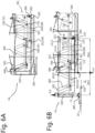
- Figures 5A to 5C show three stages to provide the outrigger beam 200 from the retracted position P4 of figure 5A , in which the outrigger beam is located within the outrigger frame 100, to a first semi-extended position P2 of figure 5C , in which the outrigger beam is partly extended from the outrigger frame.
- the first semi-extended position P2 is in between the retracted position P4 and the extended position P1 of figure 4D .
- Figure 5B shows an intermediate position of the outrigger beam 200 when moving along the horizontal extension direction E with respect to the outrigger frame 100 to the first semi-extended position of figure 5C .
- the outrigger support 300 is in the supporting position SP in the first semi-extended position P2 shown in figure 5C to support the outrigger assembly on the supporting surface S.
- the rotatable cam is further rotated to be inserted into the second recess 212 provided in the top side surface of the outrigger beam 200 in the first semi-extended position.
- the outrigger beam is again coupled to the outrigger frame through the slider element 500.
- the first end 501 of the slider element is held in the elongated slot 250 in the bottom region of the outrigger beam 200 by the projection of the slider element extending into the slot.
- Figure 5C of the first semi-extended position of the outrigger beam shows that the projection at the first end 501 of the slider element cooperates with the first slot end 251.
- the projection at the second end 502 of the slider element 500 cooperates with a second stop 112 in the bottom region of the outrigger frame 100.
- the outrigger support 300 supports the outrigger beam and outrigger frame.
- the outrigger support 300 causes a third vertical force Fv3 acting upwards at the first location L1 on the distal end 202 of the outrigger beam.
- the outrigger frame is again supported on the outrigger beam through the cam 400 that is now inserted into the second recess 212, which causes a fourth vertical force Fv4 acting downwards at a fifth location L5 on the outrigger beam.
- the fifth location L5 is separated from the first location L1 by a second horizontal distance Dh2 towards the proximal end 201 of the outrigger beam.
- the second horizontal distance Dh2 is smaller than the first horizontal distance Dh1, and the second location L5 is at a horizontal position in between the first and second locations L1, L2.
- the third and fourth vertical forces Fv3, Fv4 separated by the second horizontal distance Dh2 cause a third torque to act on the outrigger beam.
- the third torque is balanced by a fourth torque determined by interaction between the outrigger frame and the outrigger beam through again the cam 400 and slider element 500.
- the cam 400 coupled to the outrigger frame 100 and inserted into the second recess 212 causes a third horizontal force Fh3 acting outwards at a sixth location L6 on the outrigger beam.
- the fifth and sixth locations L5, L6 are the same, or virtually the same, as the fourth vertical force Fv4 and the third horizontal force Fh3 are both caused by the cam 400 acting on the outrigger beam.
- the fifth and sixth locations L5, L6 need not be the same.
- the slider element 500 by the projection at its first end 501 inserted into the slot 250 and cooperating with the first slot end 251 causes a fourth horizontal force Fh4 acting inwards at a seventh location L7 on the outrigger beam next to the first slot end 251.
- the fourth and seventh locations L4, L7 are the same locations in the embodiment shown.
- the fourth horizontal force Fh4 can be caused by the slider element since its second end 502 cooperates with the second stop 112 on the outrigger frame 100.
- the seventh location L7 is separated from the sixth location L6 by a second vertical distance Dv2 in a downward direction.
- the first and second vertical distances Dv1, Dv2 are the same in the embodiment shown.
- the third and fourth horizontal forces Fh3, Fh4 separated by the second vertical distance Dv2 cause the fourth torque to act on the outrigger beam.
- vertical force components might be present in addition to the horizontal forces. It is substantially the horizontal force components acting to cause the fourth torque.
- Figures 6A and 6B show two stages to provide the outrigger beam 200 from the retracted position P4 of figure 6A , in which the outrigger beam is located within the outrigger frame 100, to a second semi-extended position P3 of figure 6B , in which the outrigger beam is partly extended from the outrigger frame. No intermediate positions are shown. In the second semi-extended position of figure 6B the outrigger beam 200 extends less far from the outrigger frame 100 than in the first semi-extended position of figure 5C .
- the outrigger support 300 is in the supporting position SP in the second semi-extended position P3 shown in figure 6B to support the outrigger assembly on the supporting surface S.
- the outrigger support 300 causes a fifth vertical force Fv5 acting upwards at the first location L1 on the distal end 202 of the outrigger beam.
- the outrigger frame is in the second semi-extended position P3 directly supported on the outrigger beam at an eighth location L8 to cause a sixth vertical force Fv6 acting downwards at the eighth location L8 on the outrigger beam.
- the eighth location L8 is separated from the first location L1 by a third horizontal distance Dh3 towards the proximal end 201 of the outrigger beam.
- the third horizontal distance Dh3 is smaller than the first horizontal distance Dh1, and the eighth location L8 is at a horizontal position in between the first and second locations L1, L2. In the embodiment shown, the third horizontal distance Dh3 is also smaller thank the second horizontal distance Dh2, and the eighth location L8 is at a horizontal position in between the first and fifth locations L1, L5.
- the fifth and sixth vertical forces Fv5, Fv6 separated by the third horizontal distance Dh3 cause a fifth torque to act on the outrigger beam.
- the fifth torque is balanced by a sixth torque determined by direct interaction between the outrigger frame and the outrigger beam.
- the outrigger frame causes a seventh vertical force Fv7 acting downwards at a ninth location L9 on the outrigger beam.
- the eighth and ninth locations L8, L9 are actually the same, or virtually the same, in the embodiment shown, as there is a limited contact area between the upper side of the outrigger beam and the outrigger frame. Generally, the eighth and ninth locations L8, L9 need not be the same. Further, the outrigger frame causes an eighth vertical force Fv8 acting upwards at a tenth location L10 on the outrigger beam.
- the tenth location L10 is separated from the eighth location L8 by a fourth horizontal distance Dh4 in a direction toward the proximal end 201 of the outrigger beam.
- the seventh and eighth vertical forces Fv7, Fv8 separated by the fourth horizontal distance Dh4 cause the sixth torque to act on the outrigger beam. Since, the sixth and seventh vertical forces Fv6, Fv7 act on (virtually) the same location L8, L9, they will add to a single vertical force Fv6+Fv7. However, still two torques act on the outrigger beam to balance one another.
- the outrigger assembly comprises first and second outrigger beam actuators 150, 160 operable for moving the outrigger beam 200 and the outrigger frame 100 with respect to one another, and for moving the slider element 500 and the outrigger beam 200 with respect to one another.
- the first outrigger beam actuator 150 operates to move the outrigger beam 200 together with the second outrigger beam actuator 160 and the slider element 500 with respect to the outrigger frame 100.
- the second actuator 160 operates to move the outrigger beam 200 with respect to the slider element 500 and the outrigger frame 100.
- the first outrigger beam actuator 150 comprises a first outrigger actuation cylinder having a first cylinder part 151 and a first piston part 152 movable with respect to the first cylinder part and coupled to the outrigger frame 100
- the second outrigger beam actuator 160 comprises a second outrigger actuation cylinder having a second cylinder part 161 and a second piston part 162 movable with respect to the second cylinder part and couple to the outrigger beam 200.
- the first and second cylinder parts 151, 161 and the first end of the slider element are fixedly coupled to one another.
- the slider element 500 In the retracted position P4 shown in figures 4A , 5A and 6A the slider element 500 is in a first slider element position SE1, in which the second end 502 of the slider element is held by the outrigger beam 200.
- first slider element position SE1 In the first slider element position SE1 the first end 501 of the slider element is at the second slot end 252 of the slot 250, while the second end 502 of the slider element 500 is kept in a slider element recess 260 at the extreme end of the proximal end of the outrigger beam 200.
- the first outrigger beam actuator 160 is operated to extend the first piston part 152 out of the first cylinder part 151 to move and extend the outrigger beam 200 out of the outrigger frame 100, while the slider element 500 is kept in the first slider element position SE1, as is shown in figure 6B .
- the support foot 310 of the outrigger support 300 is then lowered onto the supporting surface S by operation of the support cylinder 320 to support the outrigger assembly on the supporting surface and to finally arrive in the position as shown in figure 6B .
- the second outrigger beam actuator 160 is operated to extend the second piston part 162 out of the second cylinder part 161 to move and extend the outrigger beam 200 out of the outrigger frame 100, as is shown for the intermediate position in figure 5B .
- the slider element 500 does not move with respect to the outrigger frame 100 since the first end 501 of the slider element 500 is fixedly connected to the first and second cylinder parts 151, 161.
- the first outrigger beam actuator 150 is operated to extend the first piston part 152 out of the first cylinder part 151 to further move and extend the outrigger beam 200 out of the outrigger frame 100 to arrive in the outrigger beam position as is shown in figure 5C .
- Operation of the first and second outrigger beam actuators 150, 160 may also overlap to arrive in the first semi-extended position P2 of figure 5C .
- the second end 502 of the slider element 500 will slide over the outrigger frame 100 and end up abutting against the second stop 112 on the outrigger frame.
- the cam actuator 450 is operated to rotate the cam 400 around its rotation axis 410 to move the cam into the second recess 212 in the top side of the outrigger beam.
- the support foot 310 of the outrigger support 300 is then lowered onto the supporting surface S by operation of the support cylinder 320 to support the outrigger assembly on the supporting surface and to finally arrive in the position as shown in figure 5C .
- the first outrigger beam actuator 160 is operated to extend the first piston part 152 out of the first cylinder part 151 to move and extend the outrigger beam 200 out of the outrigger frame 100, while the slider element 200 is kept in the first slider element position SE1, as has been described earlier with respect to figure 6B .
- the second end 502 of the slider element should be at a horizontal position in between first and second stops 111, 112 or, preferably, above the second stop 112, as shown in figure 4B , when the second outrigger beam actuator 160 is operated to extend the second piston part 162 out of the second cylinder part 161 to further move and extend the outrigger beam 200 out of the outrigger frame 100.
- the second outrigger beam actuator 160 is operated from the intermediate position shown in figure 4B , one arrives at the intermediate position shown in figure 4C .
- the slider element 500 does not move with respect to the outrigger frame 100 since the first end 501 of the slider element 500 is fixedly connected to the first and second cylinder parts 151, 161, as has been described earlier with respect to figure 5B .
- the first outrigger beam actuator 150 is operated to extend the first piston part 152 out of the first cylinder part 151 to further move and extend the outrigger beam 200 out of the outrigger frame 100 to arrive in the outrigger beam position as is shown in figure 4D .
- Operation of the first and second outrigger beam actuators 150, 160 may also overlap to arrive from the outrigger beam position of figure 4C into the outrigger beam position of figure 4D . This is equivalent to what has been described earlier with respect to figure 5C .
- the second end 502 of the slider element 500 will slide over the outrigger frame 100 and end up abutting against the first stop 111 on the outrigger frame.
- the cam actuator 450 is operated to rotate the cam 400 around its rotation axis 410 to move the cam into the first recess 211 in the top side of the outrigger beam.
- the support foot 310 of the outrigger support 300 is then lowered onto the supporting surface S by operation of the support cylinder 320 to support the outrigger assembly on the supporting surface and to finally arrive in the position as shown in figure 4D .
Landscapes
- Engineering & Computer Science (AREA)
- Mechanical Engineering (AREA)
- Jib Cranes (AREA)
- Vehicle Cleaning, Maintenance, Repair, Refitting, And Outriggers (AREA)
- Prostheses (AREA)
Claims (15)
- Auslegervorrichtung (10) zum Abstützen eines Fahrzeugs auf einer Stützfläche (S), wobei die Auslegervorrichtung Folgendes umfasst:- einen Auslegerrahmen (100);- einen Auslegerbalken (200),wobei der Auslegerbalken (200) entlang einer horizontalen Ausfahrrichtung (E) in Bezug auf den Auslegerrahmen (100) zwischen einer eingefahrenen Position (P4), in der sich der Auslegerbalken innerhalb des Auslegerrahmens befindet, und einer ausgefahrenen Position (P1), in der der Auslegerbalken von dem Auslegerrahmen ausgefahren ist, beweglich ist, undwobei der Auslegerbalken (200) in der ausgefahrenen Position des Auslegerbalkens ein proximales Ende (201) und ein distales Ende (202) in Bezug auf den Auslegerrahmen (100) aufweist; und- eine Auslegerstütze (300), die mit dem distalen Ende des Auslegerbalkens (200) gekoppelt ist, um die Abstützung der Auslegervorrichtung (10) auf der Stützfläche (S) in einer Stützposition (SP) der Auslegerstütze zu ermöglichen,wobei die Auslegervorrichtung so konfiguriert ist, dass in der ausgefahrenen Position des Auslegerbalkens (200) und der Stützposition der Auslegerstütze (300)- - ein erstes Drehmoment auf den Auslegerbalken (200) wirkt, wobei das erste Drehmoment durch eine erste vertikale Kraft (Fv1) bestimmt wird, die an einer ersten Stelle (L1) am distalen Ende (202) des Auslegerbalkens nach oben wirkt, und eine zweite vertikale Kraft (Fv2), die an einer zweiten Stelle (L2) auf dem Auslegerbalken nach unten wirkt, wobei die zweite Stelle von der ersten Stelle durch einen ersten horizontalen Abstand (Dh1) in Richtung des proximalen Endes (201) des Auslegerbalkens getrennt ist, wobei die ersten und zweiten vertikalen Kräfte dadurch wirken, dass der Auslegerbalken durch die Auslegerstütze (300) gestützt wird bzw. der Auslegerrahmen (100) durch den Auslegerbalken gestützt wird, und- - ein zweites Drehmoment auf den Auslegerbalken (200) wirkt, um das erste Drehmoment auszugleichen, wobei das zweite Drehmoment durch die Interaktion zwischen dem Auslegerrahmen (100) und dem Auslegerbalken bestimmt wird,dadurch gekennzeichnet, dass das zweite Drehmoment zumindest im Wesentlichen durch eine erste horizontale Kraft (Fh1), die an einer dritten Stelle (L3) auf dem Auslegerbalken in Bezug auf den Auslegerrahmen nach außen wirkt, und eine zweite horizontale Kraft (Fh2), die an einer vierten Stelle (L4) auf dem Auslegerbalken in Bezug auf den Auslegerrahmen nach innen wirkt, bestimmt wird, wobei die vierte Stelle von der dritten Stelle durch einen ersten vertikalen Abstand (Dv1) in Abwärtsrichtung getrennt ist.
- Auslegervorrichtung nach dem vorhergehenden Anspruch, wobei sich die zweite und dritte Stelle (L2, L3) am proximalen Ende (201) des Auslegerbalkens (200) befinden, optional am äußersten Ende des proximalen Endes.
- Auslegervorrichtung nach einem der vorhergehenden Ansprüche,
wobei die zweite und die dritte Stelle (L2, L3) übereinstimmende Stellen sind. - Auslegervorrichtung nach einem der vorhergehenden Ansprüche, wobei der Auslegerbalken (200) entlang der Ausfahrrichtung (E) in eine erste halb ausgefahrene Position (P2) zwischen der eingefahrenen Position (P4) und der ausgefahrenen Position (P1) beweglich ist,wobei die Auslegervorrichtung so konfiguriert ist, dass in der ersten halb ausgefahrenen Position des Auslegerbalkens (200) und der Stützposition der Auslegerstütze (300)- - ein drittes Drehmoment auf den Auslegerbalken (200) wirkt, wobei das dritte Drehmoment durch eine dritte vertikale Kraft (Fv3), die an der ersten Stelle (L1) am distalen Ende (202) des Auslegerbalkens nach oben wirkt, und eine vierte vertikale Kraft (Fv4), die an einer fünften Stelle (L5) auf dem Auslegerbalken nach unten wirkt, bestimmt wird, wobei die fünfte Stelle von der ersten Stelle durch einen zweiten horizontalen Abstand (Dh2) getrennt ist, der kleiner als der erste horizontale Abstand (Dh1) in Richtung des proximalen Endes (201) des Auslegerbalkens ist, wobei die dritten und vierten vertikalen Kräfte dadurch wirken, dass der Auslegerbalken durch die Auslegerstütze gestützt wird bzw. der Auslegerrahmen durch den Auslegerbalken gestützt wird, und- - ein viertes Drehmoment auf den Auslegerbalken (200) wirkt, um das dritte Drehmoment auszugleichen, wobei das vierte Drehmoment durch die Interaktion zwischen dem Auslegerrahmen (100) und dem Auslegerbalken bestimmt wird,wobei das vierte Drehmoment zumindest im Wesentlichen durch eine dritte horizontale Kraft (Fh3), die an einer sechsten Stelle (L6) auf dem Auslegerbalken (200) in Bezug auf den Auslegerrahmen (100) nach außen wirkt, und eine vierte horizontale Kraft (Fh4), die an einer siebten Stelle (L7) auf dem Auslegerbalken in Bezug auf den Auslegerrahmen nach innen wirkt, bestimmt wird, wobei die siebte Stelle von der sechsten Stelle durch einen zweiten vertikalen Abstand (Dv2) in Abwärtsrichtung getrennt ist,optional die fünfte und die sechste Stelle (L5, L6) übereinstimmende Stellen sind,optional die vierte und die siebte Stelle (L4, L7) übereinstimmende Stellen sind.
- Auslegervorrichtung nach einem der vorhergehenden Ansprüche, wobei der Auslegerbalken (200) entlang der Ausfahrrichtung (E) in eine zweite halb ausgefahrene Position (P3) zwischen der eingefahrenen Position (P4) und der ausgefahrenen Position (P1) beweglich ist,wobei die Auslegervorrichtung so konfiguriert ist, dass in der zweiten halb ausgefahrenen Position des Auslegerbalkens (200) und der Stützposition der Auslegerstütze (300)- - ein fünftes Drehmoment auf den Auslegerbalken (200) wirkt, wobei das fünfte Drehmoment durch eine fünfte vertikale Kraft (Fv5), die an der ersten Stelle (L1) am distalen Ende (202) des Auslegerbalkens nach oben wirkt, und eine sechste vertikale Kraft (Fv6), die an einer achten Stelle (L8) auf dem Auslegerbalken nach unten wirkt, bestimmt wird, wobei die achte Stelle von der ersten Stelle durch einen dritten horizontalen Abstand (Dh3) getrennt ist, der kleiner als der erste horizontale Abstand (Dh1) in Richtung des proximalen Endes (201) des Auslegerbalkens ist, wobei die fünften und sechsten vertikalen Kräfte dadurch wirken, dass der Auslegerbalken durch die Auslegerstütze (300) und den Auslegerrahmen (100) gestützt wird, die jeweils vom Auslegerbalken getragen werden, und- - ein sechstes Drehmoment auf den Auslegerbalken (200) wirkt, um das fünfte Drehmoment auszugleichen, wobei das sechste Drehmoment durch die Interaktion zwischen dem Auslegerrahmen (100) und dem Auslegerbalken bestimmt wird,wobei das sechste Drehmoment durch eine siebte vertikale Kraft (Fv7), die an einer neunten Stelle (L9) auf dem Auslegerbalken (200) nach unten wirkt, und eine achte vertikale Kraft (Fv8), die an einer zehnten Stelle (L10) auf dem Auslegerbalken nach oben wirkt, bestimmt wird, wobei die zehnte Stelle von der neunten Stelle durch einen vierten horizontalen Abstand (Dh4) in Richtung des proximalen Endes (201) des Auslegerbalkens getrennt ist,optional die zweite halb ausgefahrene Position (P3) zwischen der eingefahrenen Position (P4) und der ersten halb ausgefahrenen Position (P2) liegt und der dritte horizontale Abstand (Dh3) kleiner als der zweite horizontale Abstand (Dh2) ist.
- Auslegervorrichtung nach einem der vorhergehenden Ansprüche, wobei der Auslegerrahmen (100) einen beweglichen Nocken (400) umfasst, der in eine erste oder eine zweite Aussparung (211, 212) bewegt werden kann, die der zweiten und dritten Stelle (L2, L3) bzw. der fünften und sechsten Stelle (L5, L6) entspricht, um zu ermöglichen, dass die zweite vertikale Kraft (Fv2) und die erste horizontale Kraft (Fh1) bzw. die vierte vertikale Kraft (Fv4) und die dritte horizontale Kraft (Fh3) auf den Auslegerbalken (200) in der ausgefahrenen Position (P1) oder der ersten halb ausgefahrenen Position (P2) des Auslegerbalkens einwirken, wobei optional der bewegliche Nocken (400) ein drehbarer Nocken ist, optional der bewegliche Nocken durch einen Nockenbetätiger (450), optional einen Betätigungszylinder, optional einen pneumatischen, hydraulischen, elektrischen oder manuell gesteuerten Betätigungszylinder betätigt werden kann, wobei optional die erste oder zweite Aussparung in einer oberen Oberfläche des Auslegerbalkens (200) vorgesehen ist.
- Auslegervorrichtung nach einem der vorhergehenden Ansprüche, wobei der Auslegerrahmen (100) einen beweglichen Nocken (400) umfasst, der in eine erste Aussparung (211) bewegt werden kann, die der zweiten und der dritten Stelle (L2, L3) entspricht, so dass die zweite vertikale Kraft (Fv2) und die erste horizontale Kraft (Fh1) in der ausgefahrenen Position (P1) des Auslegerbalkens auf den Auslegerbalken wirken können, und in eine zweite Aussparung (212) bewegt werden kann, die der fünften und sechsten Position (L5, L6) entspricht, um zu ermöglichen, dass die vierte vertikale Kraft (Fv4) und die dritte horizontale Kraft (Fh3) auf den Auslegerbalken (200) in der ersten halb ausgefahrenen Position (P2) des Auslegerträgers wirken, wobei optional der bewegliche Nocken (400) ein drehbarer Nocken ist, optional der bewegliche Nocken durch einen Nockenbetätiger (450), optional einen Betätigungszylinder, optional einen pneumatischen, hydraulischen, elektrischen oder manuell gesteuerten Betätigungszylinder betätigt werden kann, wobei optional die erste und zweite Aussparung in einer oberen Oberfläche des Auslegerbalkens (200) vorgesehen sind.
- Auslegervorrichtung nach einem der vorhergehenden Ansprüche, wobei die Auslegervorrichtung ein Gleitelement (500) mit ersten und zweiten Enden (501, 502) umfasst, wobei das erste Ende (501) mit dem Auslegerbalken (200) zusammenwirkt und das zweite Ende (502) mit dem Auslegerrahmen (100) zusammenwirkt, um das Ausfahren des Auslegerbalkens vom Auslegerrahmen zu ermöglichen und um zu ermöglichen, dass die zweite horizontale Kraft (Fh2) in der ausgefahrenen Position (P1) des Auslegerbalkens auf den Auslegerbalken wirkt, wobei optional das erste Ende des Gleitelements verschiebbar mit dem Auslegerbalken gekoppelt ist, um eine Bewegung des Gleitelements in Bezug auf den Auslegerbalken zu ermöglichen.
- Auslegervorrichtung nach dem vorhergehenden Anspruch, wobei der Auslegerrahmen (100) einen ersten Anschlag (111) aufweist und das zweite Ende (501) des Gleitelements beim Ausfahren des Auslegerbalkens (200) aus dem Auslegerrahmen in Bezug auf den Auslegerrahmen verschiebbar ist, und das zweite Ende (502) mit dem ersten Anschlag zusammenwirkt, um der zweiten horizontalen Kraft (Fh2) zu ermöglichen, in der ausgefahrenen Position (P1) des Auslegerbalkens auf den Auslegerbalken zu wirken.
- Auslegervorrichtung nach dem vorhergehenden Anspruch in Abhängigkeit von Anspruch 4, wobei das erste Ende (501) des Gleitelements (500) mit dem Auslegerbalken (200) zusammenwirkt und das zweite Ende (502) mit dem Auslegerrahmen (100) zusammenwirkt, um das Ausfahren des Auslegerbalkens aus dem Auslegerrahmen zu ermöglichen und die Einwirkung der vierten horizontalen Kraft (Fh4) auf den Auslegerbalken in der ersten halb ausgefahrenen Position (P2) des Auslegerbalkens zu ermöglichen, wobei der Auslegerrahmen einen zweiten Anschlag (112) umfasst und das zweite Ende (502) des Gleitelements mit dem zweiten Anschlag zusammenwirkt, um zu ermöglichen, dass die vierte horizontale Kraft (Fh4) auf den Auslegerbalken in der ersten halb ausgefahrenen Position (P2) des Auslegerbalkens wi rkt.
- Auslegervorrichtung nach dem vorhergehenden Anspruch, wobei das erste Ende (501) des Gleitelements (500) verschiebbar mit dem Auslegerbalken (200) verbunden ist, um eine Bewegung des Gleitelements in Bezug auf den Auslegerbalken (200) zwischen einer ersten Gleitelementposition (SE1), in der das zweite Ende (502) des Gleitelements durch den Auslegerbalken gehalten wird, und einer zweiten Gleitelementposition (SE2), in der das zweite Ende relativ zum Auslegerrahmen (100) gleiten kann, zu ermöglichen.
- Auslegervorrichtung nach dem vorhergehenden Anspruch, wobei die Auslegervorrichtung erste und zweite Auslegerbalken-Aktuatoren (150, 160) umfasst, die zum Bewegen des Auslegerbalkens (200) und des Auslegerrahmens (100) relativ zueinander und zum Bewegen des Gleitelements (500) und des Auslegerbalkens relativ zueinander betreibbar sind.
- Auslegervorrichtung nach dem vorhergehenden Anspruch, wobei die Auslegervorrichtung so konfiguriert ist, dass der erste Auslegerbalken-Aktuator (150) betreibbar ist, um das Bewegen des Auslegerbalkens (200) zusammen mit dem zweiten Auslegerbalken-Aktuator (160) und dem Gleitelement (500) in Bezug auf den Auslegerrahmen (100) zu ermöglichen und der zweite Aktuator betreibbar ist, um das Bewegen des Auslegerbalkens in Bezug auf das Gleitelement und den Auslegerrahmen zu ermöglichen.
- Auslegervorrichtung nach dem vorhergehenden Anspruch, wobei der erste Auslegerbalken-Aktuator (1150) einen ersten Ausleger-Betätigungszylinder mit einem ersten Zylinderteil (151) und einem ersten Kolbenteil (152) umfasst, der in Bezug auf den ersten Zylinderteil beweglich ist und mit dem Auslegerrahmen (100) gekoppelt ist, wobei der zweite Auslegerbalken-Aktuator (160) einen zweiten Ausleger-Betätigungszylinder mit einem zweiten Zylinderteil (161) und einem zweiten Kolbenteil (162) umfasst, der in Bezug auf den zweiten Zylinderteil beweglich ist und mit dem Auslegerbalken (200) gekoppelt ist, und die ersten und zweiten Zylinderteile und das erste Ende des Gleitelements fest miteinander gekoppelt sind.
- Fahrzeug, das eine Auslegervorrichtung (10) nach einem der vorhergehenden Ansprüche umfasst,
wobei optional das Fahrzeug ein mobiler Kran ist.
Applications Claiming Priority (2)
| Application Number | Priority Date | Filing Date | Title |
|---|---|---|---|
| NL2019784A NL2019784B1 (en) | 2017-10-23 | 2017-10-23 | Outrigger assembly and vehicle, such as a mobile crane, comprising the outrigger assembly |
| PCT/NL2018/050695 WO2019083357A1 (en) | 2017-10-23 | 2018-10-22 | STABILIZER AND VEHICLE ASSEMBLY, SUCH AS A MOBILE CRANE, COMPRISING THE STABILIZER ASSEMBLY |
Publications (3)
| Publication Number | Publication Date |
|---|---|
| EP3700853A1 EP3700853A1 (de) | 2020-09-02 |
| EP3700853C0 EP3700853C0 (de) | 2023-11-22 |
| EP3700853B1 true EP3700853B1 (de) | 2023-11-22 |
Family
ID=60957410
Family Applications (1)
| Application Number | Title | Priority Date | Filing Date |
|---|---|---|---|
| EP18814706.0A Active EP3700853B1 (de) | 2017-10-23 | 2018-10-22 | Auslegervorrichtung und fahrzeug, wie ein mobiler kran, mit der auslegervorrichtung |
Country Status (6)
| Country | Link |
|---|---|
| EP (1) | EP3700853B1 (de) |
| JP (1) | JP7234245B2 (de) |
| KR (1) | KR102687586B1 (de) |
| CN (1) | CN111542486B (de) |
| NL (1) | NL2019784B1 (de) |
| WO (1) | WO2019083357A1 (de) |
Family Cites Families (12)
| Publication number | Priority date | Publication date | Assignee | Title |
|---|---|---|---|---|
| US3545627A (en) * | 1968-12-30 | 1970-12-08 | Letourneau Inc | Heavy duty crane for use in a narrow loading area |
| US3756424A (en) * | 1971-12-27 | 1973-09-04 | Harnischfeger Corp | Mobile crane outrigger assembly |
| JPH0786075B2 (ja) * | 1988-02-19 | 1995-09-20 | 古河機械金属株式会社 | アウトリガ操作装置 |
| JP2535042Y2 (ja) * | 1990-04-24 | 1997-05-07 | 株式会社タダノ | アウトリガ装置 |
| WO1995000372A1 (en) * | 1993-06-28 | 1995-01-05 | Kabushiki Kaisha Komatsu Seisakusho | Vehicle body levelling device for a working vehicle having outriggers |
| JP4772970B2 (ja) * | 2001-01-30 | 2011-09-14 | 株式会社タダノ | 作業車両のアウトリガ |
| DE10110176A1 (de) * | 2001-03-02 | 2002-09-05 | Putzmeister Ag | Mobiles Arbeitsgerät mit Standsicherheitsüberwachung |
| CN101457589B (zh) * | 2008-12-26 | 2011-04-13 | 三一重工股份有限公司 | 一种施工机械 |
| CN102381291B (zh) * | 2011-09-14 | 2014-09-10 | 三一汽车制造有限公司 | 一种伸缩支腿及具有该伸缩支腿的工程机械 |
| US10308487B2 (en) * | 2014-01-17 | 2019-06-04 | Tecsis Gmbh | Measurement system for determining support force |
| CN203772457U (zh) * | 2014-01-17 | 2014-08-13 | 泰科思(深圳)传感器有限公司 | 用于确定在支承结构的支承元件上的支承力的测量系统 |
| DE102015003634A1 (de) * | 2015-03-19 | 2016-09-22 | Liebherr-Werk Ehingen Gmbh | Schiebeholm zum Abstützen einer Arbeitsmaschine |
-
2017
- 2017-10-23 NL NL2019784A patent/NL2019784B1/en active
-
2018
- 2018-10-22 WO PCT/NL2018/050695 patent/WO2019083357A1/en not_active Ceased
- 2018-10-22 KR KR1020207014800A patent/KR102687586B1/ko active Active
- 2018-10-22 CN CN201880079603.1A patent/CN111542486B/zh active Active
- 2018-10-22 EP EP18814706.0A patent/EP3700853B1/de active Active
- 2018-10-22 JP JP2020543453A patent/JP7234245B2/ja active Active
Also Published As
| Publication number | Publication date |
|---|---|
| JP7234245B2 (ja) | 2023-03-07 |
| KR20200071121A (ko) | 2020-06-18 |
| WO2019083357A1 (en) | 2019-05-02 |
| EP3700853C0 (de) | 2023-11-22 |
| CN111542486B (zh) | 2021-10-29 |
| JP2021500285A (ja) | 2021-01-07 |
| CN111542486A (zh) | 2020-08-14 |
| NL2019784B1 (en) | 2019-04-29 |
| EP3700853A1 (de) | 2020-09-02 |
| KR102687586B1 (ko) | 2024-07-24 |
Similar Documents
| Publication | Publication Date | Title |
|---|---|---|
| EP2719653B1 (de) | Motorisch in vertikaler Richtung höhenverstellbarer Hubtisch, z. B. zur Verwendung im Karosseriebau der Kfz-Industrie | |
| US10647553B2 (en) | Mobile crane and method for angling a main jib extension relative to a main jib of a mobile crane | |
| DE69927070T2 (de) | Lateraler Ausleger für bewegliche Arbeitshebebühne mit vertikalem Mast | |
| EP2210853B1 (de) | Verriegelungssystem für Teleskopkranausleger mit verschiebbarer Verriegelungseinheit | |
| EP3071512A2 (de) | Fahrzeug und verfahren zur durchführung von lageraktionen mit lagereinheiten | |
| NL2007189C2 (en) | Lattice piece and crane. | |
| EP3177560B1 (de) | Gestängeanordnung mit geradliniger bewegung für fahrzeugaufzug | |
| KR20070051688A (ko) | 개선된 스트래들 캐리어 | |
| EP1698584A1 (de) | Flurförderzeug | |
| EP2468131B1 (de) | Ausziehbarer Tisch | |
| CN109849170A (zh) | 一种插抱两用式抱砖机及其方法 | |
| WO2019083357A1 (en) | STABILIZER AND VEHICLE ASSEMBLY, SUCH AS A MOBILE CRANE, COMPRISING THE STABILIZER ASSEMBLY | |
| DE102011115357B4 (de) | Auslegerelement, Teleskopausleger, Verbolzsystem sowie Baufahrzeug | |
| WO2014139842A1 (de) | Hubgerüst für ein flurförderzeug | |
| WO2012037926A2 (de) | Vorrichtung zur aufnahme eines gabelträgerprofils | |
| EP1340709A1 (de) | Transportanlage zum Transport von Bauteilen | |
| US20140216188A1 (en) | Teleskopierbare Schiebeholmvorrichtung und Verfahren zu deren Nutzung | |
| EP3339237B1 (de) | Hydraulikkran | |
| WO2017153724A1 (en) | Elevating platform | |
| EP2318301B1 (de) | Hebebühne | |
| CA2695351C (en) | Hoist | |
| EP3305589B1 (de) | Ladebordwand mit sturzsicherung | |
| DE10004622A1 (de) | Gabelstapler | |
| EP3336043B1 (de) | Hydraulikkran | |
| DE102004035416B4 (de) | Abstützvorrichtung für Traggestelle mit vorkragenden Lasten |
Legal Events
| Date | Code | Title | Description |
|---|---|---|---|
| STAA | Information on the status of an ep patent application or granted ep patent |
Free format text: STATUS: UNKNOWN |
|
| STAA | Information on the status of an ep patent application or granted ep patent |
Free format text: STATUS: THE INTERNATIONAL PUBLICATION HAS BEEN MADE |
|
| PUAI | Public reference made under article 153(3) epc to a published international application that has entered the european phase |
Free format text: ORIGINAL CODE: 0009012 |
|
| STAA | Information on the status of an ep patent application or granted ep patent |
Free format text: STATUS: REQUEST FOR EXAMINATION WAS MADE |
|
| 17P | Request for examination filed |
Effective date: 20200417 |
|
| AK | Designated contracting states |
Kind code of ref document: A1 Designated state(s): AL AT BE BG CH CY CZ DE DK EE ES FI FR GB GR HR HU IE IS IT LI LT LU LV MC MK MT NL NO PL PT RO RS SE SI SK SM TR |
|
| AX | Request for extension of the european patent |
Extension state: BA ME |
|
| DAV | Request for validation of the european patent (deleted) | ||
| DAX | Request for extension of the european patent (deleted) | ||
| STAA | Information on the status of an ep patent application or granted ep patent |
Free format text: STATUS: EXAMINATION IS IN PROGRESS |
|
| 17Q | First examination report despatched |
Effective date: 20210608 |
|
| GRAP | Despatch of communication of intention to grant a patent |
Free format text: ORIGINAL CODE: EPIDOSNIGR1 |
|
| STAA | Information on the status of an ep patent application or granted ep patent |
Free format text: STATUS: GRANT OF PATENT IS INTENDED |
|
| INTG | Intention to grant announced |
Effective date: 20230510 |
|
| GRAS | Grant fee paid |
Free format text: ORIGINAL CODE: EPIDOSNIGR3 |
|
| GRAA | (expected) grant |
Free format text: ORIGINAL CODE: 0009210 |
|
| STAA | Information on the status of an ep patent application or granted ep patent |
Free format text: STATUS: THE PATENT HAS BEEN GRANTED |
|
| AK | Designated contracting states |
Kind code of ref document: B1 Designated state(s): AL AT BE BG CH CY CZ DE DK EE ES FI FR GB GR HR HU IE IS IT LI LT LU LV MC MK MT NL NO PL PT RO RS SE SI SK SM TR |
|
| REG | Reference to a national code |
Ref country code: GB Ref legal event code: FG4D |
|
| REG | Reference to a national code |
Ref country code: CH Ref legal event code: EP |
|
| REG | Reference to a national code |
Ref country code: DE Ref legal event code: R096 Ref document number: 602018061523 Country of ref document: DE |
|
| REG | Reference to a national code |
Ref country code: IE Ref legal event code: FG4D |
|
| U01 | Request for unitary effect filed |
Effective date: 20231221 |
|
| U07 | Unitary effect registered |
Designated state(s): AT BE BG DE DK EE FI FR IT LT LU LV MT NL PT SE SI Effective date: 20240108 |
|
| PG25 | Lapsed in a contracting state [announced via postgrant information from national office to epo] |
Ref country code: GR Free format text: LAPSE BECAUSE OF FAILURE TO SUBMIT A TRANSLATION OF THE DESCRIPTION OR TO PAY THE FEE WITHIN THE PRESCRIBED TIME-LIMIT Effective date: 20240223 |
|
| PG25 | Lapsed in a contracting state [announced via postgrant information from national office to epo] |
Ref country code: IS Free format text: LAPSE BECAUSE OF FAILURE TO SUBMIT A TRANSLATION OF THE DESCRIPTION OR TO PAY THE FEE WITHIN THE PRESCRIBED TIME-LIMIT Effective date: 20240322 |
|
| PG25 | Lapsed in a contracting state [announced via postgrant information from national office to epo] |
Ref country code: ES Free format text: LAPSE BECAUSE OF FAILURE TO SUBMIT A TRANSLATION OF THE DESCRIPTION OR TO PAY THE FEE WITHIN THE PRESCRIBED TIME-LIMIT Effective date: 20231122 |
|
| PG25 | Lapsed in a contracting state [announced via postgrant information from national office to epo] |
Ref country code: IS Free format text: LAPSE BECAUSE OF FAILURE TO SUBMIT A TRANSLATION OF THE DESCRIPTION OR TO PAY THE FEE WITHIN THE PRESCRIBED TIME-LIMIT Effective date: 20240322 Ref country code: GR Free format text: LAPSE BECAUSE OF FAILURE TO SUBMIT A TRANSLATION OF THE DESCRIPTION OR TO PAY THE FEE WITHIN THE PRESCRIBED TIME-LIMIT Effective date: 20240223 Ref country code: ES Free format text: LAPSE BECAUSE OF FAILURE TO SUBMIT A TRANSLATION OF THE DESCRIPTION OR TO PAY THE FEE WITHIN THE PRESCRIBED TIME-LIMIT Effective date: 20231122 |
|
| PG25 | Lapsed in a contracting state [announced via postgrant information from national office to epo] |
Ref country code: RS Free format text: LAPSE BECAUSE OF FAILURE TO SUBMIT A TRANSLATION OF THE DESCRIPTION OR TO PAY THE FEE WITHIN THE PRESCRIBED TIME-LIMIT Effective date: 20231122 Ref country code: PL Free format text: LAPSE BECAUSE OF FAILURE TO SUBMIT A TRANSLATION OF THE DESCRIPTION OR TO PAY THE FEE WITHIN THE PRESCRIBED TIME-LIMIT Effective date: 20231122 Ref country code: NO Free format text: LAPSE BECAUSE OF FAILURE TO SUBMIT A TRANSLATION OF THE DESCRIPTION OR TO PAY THE FEE WITHIN THE PRESCRIBED TIME-LIMIT Effective date: 20240222 Ref country code: HR Free format text: LAPSE BECAUSE OF FAILURE TO SUBMIT A TRANSLATION OF THE DESCRIPTION OR TO PAY THE FEE WITHIN THE PRESCRIBED TIME-LIMIT Effective date: 20231122 |
|
| PG25 | Lapsed in a contracting state [announced via postgrant information from national office to epo] |
Ref country code: CZ Free format text: LAPSE BECAUSE OF FAILURE TO SUBMIT A TRANSLATION OF THE DESCRIPTION OR TO PAY THE FEE WITHIN THE PRESCRIBED TIME-LIMIT Effective date: 20231122 |
|
| PG25 | Lapsed in a contracting state [announced via postgrant information from national office to epo] |
Ref country code: SK Free format text: LAPSE BECAUSE OF FAILURE TO SUBMIT A TRANSLATION OF THE DESCRIPTION OR TO PAY THE FEE WITHIN THE PRESCRIBED TIME-LIMIT Effective date: 20231122 |
|
| PG25 | Lapsed in a contracting state [announced via postgrant information from national office to epo] |
Ref country code: SM Free format text: LAPSE BECAUSE OF FAILURE TO SUBMIT A TRANSLATION OF THE DESCRIPTION OR TO PAY THE FEE WITHIN THE PRESCRIBED TIME-LIMIT Effective date: 20231122 Ref country code: SK Free format text: LAPSE BECAUSE OF FAILURE TO SUBMIT A TRANSLATION OF THE DESCRIPTION OR TO PAY THE FEE WITHIN THE PRESCRIBED TIME-LIMIT Effective date: 20231122 Ref country code: RO Free format text: LAPSE BECAUSE OF FAILURE TO SUBMIT A TRANSLATION OF THE DESCRIPTION OR TO PAY THE FEE WITHIN THE PRESCRIBED TIME-LIMIT Effective date: 20231122 Ref country code: CZ Free format text: LAPSE BECAUSE OF FAILURE TO SUBMIT A TRANSLATION OF THE DESCRIPTION OR TO PAY THE FEE WITHIN THE PRESCRIBED TIME-LIMIT Effective date: 20231122 |
|
| REG | Reference to a national code |
Ref country code: DE Ref legal event code: R097 Ref document number: 602018061523 Country of ref document: DE |
|
| PLBE | No opposition filed within time limit |
Free format text: ORIGINAL CODE: 0009261 |
|
| STAA | Information on the status of an ep patent application or granted ep patent |
Free format text: STATUS: NO OPPOSITION FILED WITHIN TIME LIMIT |
|
| 26N | No opposition filed |
Effective date: 20240823 |
|
| U20 | Renewal fee for the european patent with unitary effect paid |
Year of fee payment: 7 Effective date: 20241004 |
|
| REG | Reference to a national code |
Ref country code: CH Ref legal event code: PL |
|
| GBPC | Gb: european patent ceased through non-payment of renewal fee |
Effective date: 20241022 |
|
| PG25 | Lapsed in a contracting state [announced via postgrant information from national office to epo] |
Ref country code: MC Free format text: LAPSE BECAUSE OF FAILURE TO SUBMIT A TRANSLATION OF THE DESCRIPTION OR TO PAY THE FEE WITHIN THE PRESCRIBED TIME-LIMIT Effective date: 20231122 |
|
| PG25 | Lapsed in a contracting state [announced via postgrant information from national office to epo] |
Ref country code: GB Free format text: LAPSE BECAUSE OF NON-PAYMENT OF DUE FEES Effective date: 20241022 |
|
| PG25 | Lapsed in a contracting state [announced via postgrant information from national office to epo] |
Ref country code: CH Free format text: LAPSE BECAUSE OF NON-PAYMENT OF DUE FEES Effective date: 20241031 |
|
| PG25 | Lapsed in a contracting state [announced via postgrant information from national office to epo] |
Ref country code: IE Free format text: LAPSE BECAUSE OF NON-PAYMENT OF DUE FEES Effective date: 20241022 |
|
| U20 | Renewal fee for the european patent with unitary effect paid |
Year of fee payment: 8 Effective date: 20251029 |
|
| PG25 | Lapsed in a contracting state [announced via postgrant information from national office to epo] |
Ref country code: CY Free format text: LAPSE BECAUSE OF FAILURE TO SUBMIT A TRANSLATION OF THE DESCRIPTION OR TO PAY THE FEE WITHIN THE PRESCRIBED TIME-LIMIT; INVALID AB INITIO Effective date: 20181022 |
|
| PG25 | Lapsed in a contracting state [announced via postgrant information from national office to epo] |
Ref country code: HU Free format text: LAPSE BECAUSE OF FAILURE TO SUBMIT A TRANSLATION OF THE DESCRIPTION OR TO PAY THE FEE WITHIN THE PRESCRIBED TIME-LIMIT; INVALID AB INITIO Effective date: 20181022 |