EP3689221A1 - Endoskop - Google Patents
Endoskop Download PDFInfo
- Publication number
- EP3689221A1 EP3689221A1 EP18861762.5A EP18861762A EP3689221A1 EP 3689221 A1 EP3689221 A1 EP 3689221A1 EP 18861762 A EP18861762 A EP 18861762A EP 3689221 A1 EP3689221 A1 EP 3689221A1
- Authority
- EP
- European Patent Office
- Prior art keywords
- slider
- wire
- engaging member
- engaged
- operating
- Prior art date
- Legal status (The legal status is an assumption and is not a legal conclusion. Google has not performed a legal analysis and makes no representation as to the accuracy of the status listed.)
- Pending
Links
Images


Classifications
-
- A—HUMAN NECESSITIES
- A61—MEDICAL OR VETERINARY SCIENCE; HYGIENE
- A61B—DIAGNOSIS; SURGERY; IDENTIFICATION
- A61B1/00—Instruments for performing medical examinations of the interior of cavities or tubes of the body by visual or photographical inspection, e.g. endoscopes; Illuminating arrangements therefor
- A61B1/00064—Constructional details of the endoscope body
- A61B1/00071—Insertion part of the endoscope body
- A61B1/0008—Insertion part of the endoscope body characterised by distal tip features
- A61B1/00098—Deflecting means for inserted tools
-
- A—HUMAN NECESSITIES
- A61—MEDICAL OR VETERINARY SCIENCE; HYGIENE
- A61B—DIAGNOSIS; SURGERY; IDENTIFICATION
- A61B1/00—Instruments for performing medical examinations of the interior of cavities or tubes of the body by visual or photographical inspection, e.g. endoscopes; Illuminating arrangements therefor
- A61B1/00002—Operational features of endoscopes
- A61B1/00039—Operational features of endoscopes provided with input arrangements for the user
- A61B1/00042—Operational features of endoscopes provided with input arrangements for the user for mechanical operation
-
- A—HUMAN NECESSITIES
- A61—MEDICAL OR VETERINARY SCIENCE; HYGIENE
- A61B—DIAGNOSIS; SURGERY; IDENTIFICATION
- A61B1/00—Instruments for performing medical examinations of the interior of cavities or tubes of the body by visual or photographical inspection, e.g. endoscopes; Illuminating arrangements therefor
- A61B1/00064—Constructional details of the endoscope body
- A61B1/00066—Proximal part of endoscope body, e.g. handles
-
- A—HUMAN NECESSITIES
- A61—MEDICAL OR VETERINARY SCIENCE; HYGIENE
- A61B—DIAGNOSIS; SURGERY; IDENTIFICATION
- A61B1/00—Instruments for performing medical examinations of the interior of cavities or tubes of the body by visual or photographical inspection, e.g. endoscopes; Illuminating arrangements therefor
- A61B1/00064—Constructional details of the endoscope body
- A61B1/00071—Insertion part of the endoscope body
- A61B1/0008—Insertion part of the endoscope body characterised by distal tip features
- A61B1/00101—Insertion part of the endoscope body characterised by distal tip features the distal tip features being detachable
-
- A—HUMAN NECESSITIES
- A61—MEDICAL OR VETERINARY SCIENCE; HYGIENE
- A61B—DIAGNOSIS; SURGERY; IDENTIFICATION
- A61B1/00—Instruments for performing medical examinations of the interior of cavities or tubes of the body by visual or photographical inspection, e.g. endoscopes; Illuminating arrangements therefor
- A61B1/00064—Constructional details of the endoscope body
- A61B1/00105—Constructional details of the endoscope body characterised by modular construction
-
- A—HUMAN NECESSITIES
- A61—MEDICAL OR VETERINARY SCIENCE; HYGIENE
- A61B—DIAGNOSIS; SURGERY; IDENTIFICATION
- A61B1/00—Instruments for performing medical examinations of the interior of cavities or tubes of the body by visual or photographical inspection, e.g. endoscopes; Illuminating arrangements therefor
- A61B1/00064—Constructional details of the endoscope body
- A61B1/0011—Manufacturing of endoscope parts
-
- A—HUMAN NECESSITIES
- A61—MEDICAL OR VETERINARY SCIENCE; HYGIENE
- A61B—DIAGNOSIS; SURGERY; IDENTIFICATION
- A61B1/00—Instruments for performing medical examinations of the interior of cavities or tubes of the body by visual or photographical inspection, e.g. endoscopes; Illuminating arrangements therefor
- A61B1/00112—Connection or coupling means
- A61B1/00121—Connectors, fasteners and adapters, e.g. on the endoscope handle
- A61B1/00128—Connectors, fasteners and adapters, e.g. on the endoscope handle mechanical, e.g. for tubes or pipes
-
- A—HUMAN NECESSITIES
- A61—MEDICAL OR VETERINARY SCIENCE; HYGIENE
- A61B—DIAGNOSIS; SURGERY; IDENTIFICATION
- A61B1/00—Instruments for performing medical examinations of the interior of cavities or tubes of the body by visual or photographical inspection, e.g. endoscopes; Illuminating arrangements therefor
- A61B1/012—Instruments for performing medical examinations of the interior of cavities or tubes of the body by visual or photographical inspection, e.g. endoscopes; Illuminating arrangements therefor characterised by internal passages or accessories therefor
- A61B1/018—Instruments for performing medical examinations of the interior of cavities or tubes of the body by visual or photographical inspection, e.g. endoscopes; Illuminating arrangements therefor characterised by internal passages or accessories therefor for receiving instruments
-
- G—PHYSICS
- G02—OPTICS
- G02B—OPTICAL ELEMENTS, SYSTEMS OR APPARATUS
- G02B23/00—Telescopes, e.g. binoculars; Periscopes; Instruments for viewing the inside of hollow bodies; Viewfinders; Optical aiming or sighting devices
- G02B23/24—Instruments or systems for viewing the inside of hollow bodies, e.g. fibrescopes
-
- A—HUMAN NECESSITIES
- A61—MEDICAL OR VETERINARY SCIENCE; HYGIENE
- A61B—DIAGNOSIS; SURGERY; IDENTIFICATION
- A61B1/00—Instruments for performing medical examinations of the interior of cavities or tubes of the body by visual or photographical inspection, e.g. endoscopes; Illuminating arrangements therefor
- A61B1/00131—Accessories for endoscopes
- A61B1/00137—End pieces at either end of the endoscope, e.g. caps, seals or forceps plugs
-
- A—HUMAN NECESSITIES
- A61—MEDICAL OR VETERINARY SCIENCE; HYGIENE
- A61B—DIAGNOSIS; SURGERY; IDENTIFICATION
- A61B1/00—Instruments for performing medical examinations of the interior of cavities or tubes of the body by visual or photographical inspection, e.g. endoscopes; Illuminating arrangements therefor
- A61B1/005—Flexible endoscopes
- A61B1/0051—Flexible endoscopes with controlled bending of insertion part
- A61B1/0052—Constructional details of control elements, e.g. handles
-
- A—HUMAN NECESSITIES
- A61—MEDICAL OR VETERINARY SCIENCE; HYGIENE
- A61B—DIAGNOSIS; SURGERY; IDENTIFICATION
- A61B1/00—Instruments for performing medical examinations of the interior of cavities or tubes of the body by visual or photographical inspection, e.g. endoscopes; Illuminating arrangements therefor
- A61B1/005—Flexible endoscopes
- A61B1/0051—Flexible endoscopes with controlled bending of insertion part
- A61B1/0057—Constructional details of force transmission elements, e.g. control wires
Definitions
- the distal end member is provided with a forceps elevator (hereinafter also referred to as an "elevator").
- the operating part is provided with a treatment tool erection mechanism that changes the posture of the elevator between an erected position and a lodged position.
- JP1994-315458A JP-H06-315458A
- EP1759626B a body fluid adheres to the distal end member of the insertion part including the elevator and a guide tube through which the wire is inserted.
- the endoscopes are subjected to cleaning and disinfection treatment, using a cleaning liquid and a disinfectant solution.
- the diameter of the guide tube is small and the wire is inserted through the guide tube. Therefore, in order to obtain a sufficient cleaning effect, substantial time and effort are taken for cleaning.
- the invention has been made in view of such circumstances, and an object thereof is to provide an endoscope that can easily perform the attachment and detachment work of a proximal end side of a wire with respect to a slider.
- the endoscope 10 comprises an operating part 22 in which an erection operating lever 20 is provided, and an insertion part 24 that is provided on a distal end side of the operating part 22 and is inserted into a subject.
- the erection operating lever 20 is equivalent to an operating part of the invention.
- the insertion part 24 is configured such that the distal end part 26, a bending part 52, and a flexible part 54 are coupled to each other from a distal end side toward a proximal end side.
- the operating part 22 is formed in a substantially cylindrical shape as a whole and has a longitudinal axis A in a Y(+)-Y(-) direction. Additionally, a pair of angle knobs 64 and 64, which bends the bending part 52, is disposed in the operating part 22. The pair of angle knobs 64 and 64 is provided on the same axis in a rotationally movable manner.
- the flexible part 54 has a spiral tube (not illustrated) obtained by spirally winding a thin metallic beltlike sheet having elasticity.
- the flexible part 54 is configured by covering the outside of the spiral tube with a tubular net knit with metal wires and covering an outer peripheral surface of the net with a tubular outer cover from a resin.
- the endoscope 10 of the embodiment configured as described above is a side viewing endoscope used as a duodenoscope, and the insertion part 24 is inserted into the subject via an oral cavity.
- the insertion part 24 is inserted from the esophagus through the stomach to the duodenum, and treatment, such as a predetermined examination or curing, is performed.
- the distal end of the wire 60 is provided with an engaging member 100.
- the elevator 30 is provided with a housing groove 102 that is engaged with the engaging member 100 in an engageable and disengageable manner and is formed with an opening 104 on the X(+) direction side.
- the distal end of the wire 60 is coupled to the elevator 30 by housing the engaging member 100 provided at the distal end of the wire 60 in the housing groove 102 via the opening 104.
- the engaging member 100 is a spherical body
- the housing groove 102 is a spherical recess that houses the spherical engaging member 100.
- the shapes of the engaging member 100 and the housing groove 102 are not limited to the above shapes, the sliding resistance between the engaging member 100 and the housing groove 102 that occurs due to the push/pull operation of the wire 60 can be reduced by forming the engaging member 100 as a spherical body and forming the housing groove 102 as a spherical recess. Therefore, the push/pull operation of the wire 60 can be smoothly performed.
- Fig. 9 is a perspective view illustrating the configuration of the erection operating mechanism 120.
- a sheathing case (not illustrated) of the operating part 22 is omitted, and the inside of the operating part 22 is illustrated in a simplified manner.
- the first lever 130 has one end part 130A and the other end part 130B, and a linear cam groove 136 is formed from the one end part 130A to the other end part 130B. Additionally, a rotating shaft 138 is provided at the one end part 130A of the first lever 130. The rotating shaft 138 is disposed to be inserted through a through-hole (not illustrated) formed in the base member 98 and is rotatably attached to the base member 98 via an O-ring 140 provided on the rotating shaft 138. An internal space of the operating part 22 is sealed by the O-ring 140 from the slider housing space 150 illustrated in Fig. 6 .
- the base member 98 is constituted of a plate-shaped body part 98A disposed along the longitudinal axis A of the operating part 22, a wall part 98B provided in a direction orthogonal to the body part 98A on a side part of the body part 98A, a fan-shaped proximal end wall 98C that couples respective proximal end parts of the body part 98A and the wall part 98B to each other, and a fan-shaped distal end wall 98D that couples respective distal end parts of the body part 98A and the wall part 98B to each other, an opening (not illustrated) is formed in the distal end wall 98D, and the opening part 94 (refer to Fig.
- the slider 96 is disposed in the slider housing space 150 and moves in the longitudinal direction of the operating part 22 depending on the operation of the erection operating lever 20 so as to be movable forward and backward. That is, in a case where the erection operating lever 20 is operated, the slider 96 moves via the erection operating mechanism 120. As a result, the wire 60 (refer to Fig. 2 ) coupled to the slider 96 is pushed and pulled.
- a protruding strip 97 along the longitudinal axis A is formed on a lower surface of the slider 96. Additionally, as illustrated in Figs. 11 and 12 , a recessed strip 99 along the longitudinal axis A is formed in an upper surface of the body part 98A of the base member 98. The slider 96 moves smoothly along the longitudinal axis A as the protruding strip 97 is slidably engaged with the recessed strip 99.
- connection structure in which the proximal end side of the wire 60 is connected to the slider 96 will be described.
- Fig. 13 is an assembling perspective view illustrating a connection structure of a first embodiment in which the proximal end side of the wire 60 is connected to the slider 96.
- the engaging member 154 is provided on the proximal end side of the wire 60.
- the engaging member 154 is configured to be engageable with the engaged part 152 by being pushed into the engaged part 152 from the lateral side orthogonal to the movement direction of the slider 96.
- the push direction in which the engaging member 154 is pushed into the engaged part 152 is illustrated by arrow E.
- connection work of connecting the proximal end side of the wire 60 to the slider 96 by the connection structure of the first embodiment will be described.
- connection work of connecting the proximal end side of the wire 60 to the slider 96 can be performed simply by the work of pushing the engaging member 154 into the engaged part 152.
- the proximal end side of the wire 60 can be easily connected to the slider 96.
- the wire 60 is pushed from the opening part 94 illustrated in Fig. 6 , and the elevator 30 is located at the lodged position of Fig. 2 from the erected position of Fig. 3 . Thereafter, the wire 60 is further pushed so as to separate the engaging member 100 from the inside of the housing groove 102 to the outside of the opening 104. By this work, the distal end of the wire 60 is detached from the elevator 30. Next, the wire 60 is pulled out from the opening part 94 to the outside to empty the wire channel 62. Thereafter, the distal end member 28, the elevator 30, and the wire channel 62 are cleaned.
- connection structure of the first embodiment pulls out the engaging member 154 from the engaged part 152 to a direction (the direction of arrow D) opposite to the pushing direction (the direction of arrow E) of the engaging member 154 with respect to the engaged part 152 carried out at the time of the connection work.
- the detachment work is completed simply by this pulling-out work. Therefore, according to the connection structure of the first embodiment, the proximal end side of the wire 60 can be easily detached from the slider 96.
- connection work of connecting the proximal end side of the wire 60 to the slider 96 can be performed simply by the work of pushing the engaging member 154 into the engaged part 152.
- detachment work of detaching the proximal end side of the wire 60 from the slider 96 can be performed simply by the work of pulling out the engaging member 154 from the engaged part 152.
- connection structure of the first embodiment comprises the positioning receiving part 158 and the positioning part 162
- the engagement between the engaged part 152 and the engaging member 154 becomes easy by engaging the positioning part 162 with the positioning receiving part 158. Additionally, by engaging the positioning part 162 with the positioning receiving part 158, the engaging member 154 can be prevented from slipping out from the engaged part 152 in the axial direction of the wire 60.
- an engaged part 172 is formed on a front surface 170A of the slider 170.
- the engaged part 172 is recessed in the front surface 170A of the slider 170 such that an opening part 172A of the engaged part 172 faces a lateral side (a direction of arrow F) orthogonal to a movement direction of the slider 170.
- the engaged part 172 is formed in a hemispherical shape.
- a wire insertion passage 174 is formed in the slider 170.
- the wire insertion passage 174 is a passage that allows an opening part 176 disposed at a position facing the opening part 94 of the wire channel 62 and an opening part 178 (to refer to Fig.
- the engaging member 180 which is engageable with the engaged part 172, is formed as a spherical body.
- the engaging member 180 is pushed into the engaged part 172 in a direction of arrow G of Fig. 14 from the lateral side orthogonal to the movement direction of the slider 170. As a result, the engaging member 180 is engaged with the engaged part 172 with elasticity.
- Fig. 16A is a front view of the engaging member 180 illustrating a state where the proximal end side of the wire 60 is inserted into the sandwiching part 182 of the engaging member 180.
- Fig. 16B is a top view of Fig. 16A .
- Fig. 16C is a cross-sectional view of the engaging member 180 taken along line 16-16 of Fig. 16A .
- Fig. 16D is an explanatory view illustrating the state of the sandwiching part 182 in a case where the engaging member 180 is engaged with the engaged part 172.
- connection work of connecting the proximal end side of the wire 60 to the slider 96 by the connection structure of the second embodiment will be described.
- the erection operating lever 20 (refer to Fig. 9 ) is operated to locate the slider 170 at the erected position of Fig. 15 .
- the engaging member 180 receives forces in the directions of arrows H from the engaged part 172 and is elastically deformed in a direction in which a gap of the sandwiching part 182 becomes narrower. As a result, the proximal end side of the wire 60 is firmly sandwiched by the sandwiching part 182 and is fixed to the engaging member 180. Thus, the above connection work is completed.
- the engaging member 180 is pulled out from the engaged part 172 to a direction (a direction of arrow F) opposite to the pushing direction (a direction of arrow G) of the engaging member 180 with respect to the engaged part 172 carried out at the time of the connection work.
- the detachment work is completed simply by this pulling-out work. Therefore, according to the connection structure of the second embodiment, the proximal end side of the wire 60 can be easily detached from the slider 170.
- the jig 190 may be attached to the proximal end side of the wire 60.
- Fig. 18 is an explanatory view in which the jig 190 is attached to the proximal end side of the wire 60.
- a projection 194 holding the jig 190 may be provided in the operating part 22.
- the jig 190 is held by the operating part 22 by engaging a recess 196 formed in the jig 190 with the projection 194.
- the jig 190 can be prevented from becoming obstructive during the operation of the endoscope 10 (refer to Fig. 1 ).
- Fig. 19 is an assembling perspective view illustrating constituent members of the connection structure of the third embodiment.
- a state before the proximal end side of the wire 60 is connected to a slider 200 is illustrated in Fig. 19 .
- the state of an unlocked position in the connection structure of the third embodiment is illustrated in Fig. 20 .
- the state of a locked position in the connection structure of the third embodiment is illustrated in Fig. 21 .
- connection work of connecting the proximal end side of the wire 60 to the slider 200 by the connection structure of the third embodiment will be described.
- connection work of connecting the proximal end side of the wire 60 to the slider 200 can also be performed simply by the work of pushing the engaging member 210 into the engaged part 202.
- the proximal end side of the wire 60 can also be detached from the slider 200 simply by the work of pulling the engaging member 210 from the engaged part 202.
- connection structure of the third embodiment the attachment and detachment work of the proximal end side of the wire 60 with respect to the slider 200 can be easily performed similarly to the connection structures of the above-described respective embodiments.
- the locking recess 234 is provided in the slider 200, and the locking member 218 is provided on the engaging member 210 side.
- the locking member 218 may be provided in the slider 200, and the locking recess 234 may be provided on the engaging member 210 side.
- the engaging member 210 cannot engage with the engaged part 202 only in a case where the slider 200 is located at the position of Fig. 19 , that is, and the slider 200 is located at the erected position.
- the engaging member 210 is engaged with the engaged part 202 at positions other than the position of Fig. 19 in a state where the elevator 30 is connected to the wire 60 in an erected state (refer to Fig. 3 )
- the engaging member 210 can engage with the engaged part 202 only at the position of Fig. 19 .
- the problem that the operation of the slider 200 becomes impossible can be solved.
- the escape part 236 may be formed at a position corresponding to the lodged position of the slider 200.
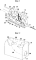
- the engaged part 242 is formed on a front surface 240A of the slider 240.
- the engaged part 242 is recessed in the front surface 240A of the slider 240 such that an opening part 242A of the engaged part 242 faces the lateral side (a direction of arrow P) orthogonal to the movement direction of the slider 240.
- a wire insertion passage 244 is formed in the slider 240.
- Fig. 29 is an enlarged perspective view illustrating the structure of the slider 240.
- connection structure of the fourth embodiment comprises a locking mechanism.
- This locking mechanism is switchable between a locked position (refer to Fig. 28 ) where release of an engaged state between the engaging member 250 and the engaged part 242 is prevented and an unlocked position (refer to Fig. 27 ) where the release of the engaged state between the engaging member 250 and the engaged part 242 is allowed.
- the distal end of the wire 60 is inserted through the wire channel 62 via the wire insertion passage 244, the opening part 246, and the opening part 94 (refer to Fig. 26 ) from the opening part 248 (refer to Fig. 29 ) of the slider 240. Then, the distal end of the wire 60 is coupled to the elevator 30 (refer to Fig. 3 ).
- the erection operating lever 20 (refer to Fig. 9 ) is operated to locate the slider 240 at the erected position of Fig. 26 .
- connection structure of the fourth embodiment the following work can be easily performed using a jig.
- the above work is the work of pushing the engaging member 250 into the engaged part 242, the locking work of rotating the engaging member 250 from the unlocked position to the locked position, the unlocking work of rotating the engaging member 250 from the locked position to the unlocked position, and the work of pulling the engaging member 250 from the engaged part 242.
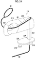
- the jig 260 comprises a knob 262, and two pins 264 and 266 provided to protrude from an end part of the knob 262. Additionally, a flat end surface 250A of the engaging member 250 is provided with a hole 268 into which the pin 264 is fitted, and a hole 270 into which the pin 266 is fitted.
- the engaging member 250 is attachably and detachably attached to the jig 260 (refer to Fig. 30 ) as the pin 264 is fitted into the hole 268 and the pin 266 is fitted into the hole 270.
- Fig. 34 is an enlarged perspective view of main parts in which the cam pin 252 is engaged with the cam groove 254 by the rotation of the jig 260.
- the unlocking work is performed.
- the jig 260 is rotated in a direction of arrow S of Fig. 32 .
- the engagement between the cam pin 252 and the cam groove 254 is released and the unlocked position (refer to Fig. 33 ).
- the jig 260 illustrated in Figs. 30 to 34 may be detached from the engaging member 250 or may be mounted on the engaging member 250 as it is.
- the duodenoscope has been exemplified and described as the endoscope 10.
- the invention can be applied to various endoscopes, such as an ultrasonic endoscope.
Landscapes
- Health & Medical Sciences (AREA)
- Life Sciences & Earth Sciences (AREA)
- Surgery (AREA)
- Engineering & Computer Science (AREA)
- Physics & Mathematics (AREA)
- Optics & Photonics (AREA)
- Medical Informatics (AREA)
- General Health & Medical Sciences (AREA)
- Pathology (AREA)
- Nuclear Medicine, Radiotherapy & Molecular Imaging (AREA)
- Biomedical Technology (AREA)
- Heart & Thoracic Surgery (AREA)
- Biophysics (AREA)
- Molecular Biology (AREA)
- Animal Behavior & Ethology (AREA)
- Radiology & Medical Imaging (AREA)
- Public Health (AREA)
- Veterinary Medicine (AREA)
- Mechanical Engineering (AREA)
- Manufacturing & Machinery (AREA)
- Astronomy & Astrophysics (AREA)
- General Physics & Mathematics (AREA)
- Endoscopes (AREA)
- Instruments For Viewing The Inside Of Hollow Bodies (AREA)
Applications Claiming Priority (2)
| Application Number | Priority Date | Filing Date | Title |
|---|---|---|---|
| JP2017186561 | 2017-09-27 | ||
| PCT/JP2018/035324 WO2019065580A1 (ja) | 2017-09-27 | 2018-09-25 | 内視鏡 |
Publications (2)
| Publication Number | Publication Date |
|---|---|
| EP3689221A1 true EP3689221A1 (de) | 2020-08-05 |
| EP3689221A4 EP3689221A4 (de) | 2020-10-07 |
Family
ID=65902921
Family Applications (1)
| Application Number | Title | Priority Date | Filing Date |
|---|---|---|---|
| EP18861762.5A Pending EP3689221A4 (de) | 2017-09-27 | 2018-09-25 | Endoskop |
Country Status (5)
| Country | Link |
|---|---|
| US (1) | US11925316B2 (de) |
| EP (1) | EP3689221A4 (de) |
| JP (1) | JP7114617B2 (de) |
| CN (1) | CN111093464B (de) |
| WO (1) | WO2019065580A1 (de) |
Cited By (2)
| Publication number | Priority date | Publication date | Assignee | Title |
|---|---|---|---|---|
| CN113208545A (zh) * | 2021-03-25 | 2021-08-06 | 北京大学 | 内窥镜装置 |
| WO2023150670A1 (en) * | 2022-02-07 | 2023-08-10 | Boston Scientific Scimed, Inc. | Endoscope elevator actuators |
Families Citing this family (10)
| Publication number | Priority date | Publication date | Assignee | Title |
|---|---|---|---|---|
| US20110067641A1 (en) * | 2008-05-16 | 2011-03-24 | Atmocean, Inc. | Methods and Apparatus For Increasing Upper-Level Fish Populations |
| EP3689222A4 (de) * | 2017-09-28 | 2020-12-16 | Fujifilm Corporation | Endoskop |
| CN111757697A (zh) * | 2018-02-23 | 2020-10-09 | 富士胶片株式会社 | 内窥镜 |
| WO2021187298A1 (ja) * | 2020-03-18 | 2021-09-23 | 富士フイルム株式会社 | 内視鏡 |
| EP4138629A1 (de) * | 2020-04-24 | 2023-03-01 | Ambu A/S | Bremsmechanismus für ein drehbares betätigungselement einer medizinischen vorrichtung |
| JP7463233B2 (ja) * | 2020-08-26 | 2024-04-08 | 富士フイルム株式会社 | 内視鏡、及び装着部品 |
| WO2022071566A1 (ja) * | 2020-10-02 | 2022-04-07 | 富士フイルム株式会社 | 内視鏡 |
| JP7758722B2 (ja) * | 2021-02-26 | 2025-10-22 | 富士フイルム株式会社 | 内視鏡 |
| EP4408254A4 (de) * | 2021-09-30 | 2025-07-09 | Noah Medical Corp | Systeme und verfahren für einen konfigurierbaren endoskopbiegeabschnitt |
| US20250352041A1 (en) * | 2024-05-14 | 2025-11-20 | Boston Scientific Scimed, Inc. | Elevators for medical devices |
Family Cites Families (21)
| Publication number | Priority date | Publication date | Assignee | Title |
|---|---|---|---|---|
| JPS607743B2 (ja) | 1979-06-30 | 1985-02-26 | 日本マイヤ−株式会社 | ジヤカ−ドレ−ス地およびその編成方法 |
| JPS62227312A (ja) * | 1986-03-27 | 1987-10-06 | 旭光学工業株式会社 | 内視鏡の湾曲操作ワイヤの取付構造 |
| JPH045802A (ja) | 1990-04-23 | 1992-01-09 | Tdk Corp | 酸化物永久磁石の製造方法 |
| JPH045802U (de) * | 1990-05-08 | 1992-01-20 | ||
| US5569157A (en) * | 1993-05-07 | 1996-10-29 | Olympus Optical Co., Ltd. | Endoscope |
| JP3302096B2 (ja) | 1993-05-07 | 2002-07-15 | オリンパス光学工業株式会社 | 内視鏡 |
| JP3272134B2 (ja) * | 1993-12-28 | 2002-04-08 | オリンパス光学工業株式会社 | 内視鏡 |
| JPH06315460A (ja) * | 1993-05-10 | 1994-11-15 | Olympus Optical Co Ltd | 内視鏡 |
| JP3607743B2 (ja) * | 1995-04-20 | 2005-01-05 | オリンパス株式会社 | 内視鏡 |
| JP4589520B2 (ja) * | 2000-11-22 | 2010-12-01 | Hoya株式会社 | 内視鏡の先端部の製造方法及び内視鏡の先端部 |
| JP3772107B2 (ja) * | 2001-10-12 | 2006-05-10 | オリンパス株式会社 | 内視鏡システム |
| JP4163438B2 (ja) * | 2002-04-17 | 2008-10-08 | オリンパス株式会社 | 内視鏡 |
| JP4323210B2 (ja) * | 2003-04-28 | 2009-09-02 | オリンパス株式会社 | 内視鏡 |
| JP4689962B2 (ja) * | 2004-01-23 | 2011-06-01 | オリンパス株式会社 | 内視鏡 |
| JP4468721B2 (ja) * | 2004-03-16 | 2010-05-26 | オリンパス株式会社 | 内視鏡処置具システム |
| DE102005041454A1 (de) | 2005-08-31 | 2007-03-01 | Karl Storz Gmbh & Co. Kg | Endoskop |
| JP2011177383A (ja) * | 2010-03-02 | 2011-09-15 | Fujifilm Corp | 内視鏡の操作ワイヤ連結装置及び内視鏡 |
| JP5362142B1 (ja) * | 2012-01-31 | 2013-12-11 | オリンパスメディカルシステムズ株式会社 | 内視鏡 |
| JP5855628B2 (ja) | 2013-11-28 | 2016-02-09 | 富士フイルム株式会社 | ワイヤ押し引き装置及び内視鏡 |
| JP2015107226A (ja) * | 2013-12-04 | 2015-06-11 | オリンパス株式会社 | コイルパイプ位置固定部材、マニピュレータ、およびコイルパイプ位置固定方法 |
| JP5993530B2 (ja) * | 2014-09-16 | 2016-09-14 | オリンパス株式会社 | 内視鏡 |
-
2018
- 2018-09-25 WO PCT/JP2018/035324 patent/WO2019065580A1/ja not_active Ceased
- 2018-09-25 JP JP2019545105A patent/JP7114617B2/ja active Active
- 2018-09-25 CN CN201880058736.0A patent/CN111093464B/zh active Active
- 2018-09-25 EP EP18861762.5A patent/EP3689221A4/de active Pending
-
2020
- 2020-03-23 US US16/826,300 patent/US11925316B2/en active Active
Cited By (4)
| Publication number | Priority date | Publication date | Assignee | Title |
|---|---|---|---|---|
| CN113208545A (zh) * | 2021-03-25 | 2021-08-06 | 北京大学 | 内窥镜装置 |
| CN113208545B (zh) * | 2021-03-25 | 2022-04-01 | 北京大学 | 内窥镜装置 |
| WO2023150670A1 (en) * | 2022-02-07 | 2023-08-10 | Boston Scientific Scimed, Inc. | Endoscope elevator actuators |
| US12527463B2 (en) | 2022-02-07 | 2026-01-20 | Boston Scientific Scimed, Inc. | Endoscope elevator actuators |
Also Published As
| Publication number | Publication date |
|---|---|
| WO2019065580A1 (ja) | 2019-04-04 |
| JPWO2019065580A1 (ja) | 2020-12-24 |
| US20200214544A1 (en) | 2020-07-09 |
| CN111093464B (zh) | 2023-01-06 |
| JP7114617B2 (ja) | 2022-08-08 |
| EP3689221A4 (de) | 2020-10-07 |
| US11925316B2 (en) | 2024-03-12 |
| CN111093464A (zh) | 2020-05-01 |
Similar Documents
| Publication | Publication Date | Title |
|---|---|---|
| US11925316B2 (en) | Endoscope | |
| US11564555B2 (en) | Endoscope | |
| US11653823B2 (en) | Endoscope | |
| US11389054B2 (en) | Endoscope, wire attaching method for endoscope, and wire detaching method for endoscope | |
| US11839355B2 (en) | Endoscope | |
| CN111542252B (zh) | 内窥镜 | |
| US11889980B2 (en) | Endoscope | |
| US11484186B2 (en) | Endoscope | |
| JP7090190B2 (ja) | 内視鏡 | |
| JP7142062B2 (ja) | 内視鏡 |
Legal Events
| Date | Code | Title | Description |
|---|---|---|---|
| STAA | Information on the status of an ep patent application or granted ep patent |
Free format text: STATUS: THE INTERNATIONAL PUBLICATION HAS BEEN MADE |
|
| PUAI | Public reference made under article 153(3) epc to a published international application that has entered the european phase |
Free format text: ORIGINAL CODE: 0009012 |
|
| STAA | Information on the status of an ep patent application or granted ep patent |
Free format text: STATUS: REQUEST FOR EXAMINATION WAS MADE |
|
| 17P | Request for examination filed |
Effective date: 20200323 |
|
| AK | Designated contracting states |
Kind code of ref document: A1 Designated state(s): AL AT BE BG CH CY CZ DE DK EE ES FI FR GB GR HR HU IE IS IT LI LT LU LV MC MK MT NL NO PL PT RO RS SE SI SK SM TR |
|
| AX | Request for extension of the european patent |
Extension state: BA ME |
|
| A4 | Supplementary search report drawn up and despatched |
Effective date: 20200908 |
|
| RIC1 | Information provided on ipc code assigned before grant |
Ipc: A61B 1/00 20060101ALI20200902BHEP Ipc: G02B 23/24 20060101ALI20200902BHEP Ipc: A61B 1/018 20060101AFI20200902BHEP Ipc: A61B 1/005 20060101ALI20200902BHEP |
|
| DAV | Request for validation of the european patent (deleted) | ||
| DAX | Request for extension of the european patent (deleted) | ||
| RAP3 | Party data changed (applicant data changed or rights of an application transferred) |
Owner name: FUJIFILM CORPORATION |
|
| STAA | Information on the status of an ep patent application or granted ep patent |
Free format text: STATUS: EXAMINATION IS IN PROGRESS |
|
| 17Q | First examination report despatched |
Effective date: 20230201 |
|
| GRAP | Despatch of communication of intention to grant a patent |
Free format text: ORIGINAL CODE: EPIDOSNIGR1 |
|
| STAA | Information on the status of an ep patent application or granted ep patent |
Free format text: STATUS: GRANT OF PATENT IS INTENDED |
|
| INTG | Intention to grant announced |
Effective date: 20251024 |
|
| GRAJ | Information related to disapproval of communication of intention to grant by the applicant or resumption of examination proceedings by the epo deleted |
Free format text: ORIGINAL CODE: EPIDOSDIGR1 |
|
| STAA | Information on the status of an ep patent application or granted ep patent |
Free format text: STATUS: EXAMINATION IS IN PROGRESS |
|
| GRAP | Despatch of communication of intention to grant a patent |
Free format text: ORIGINAL CODE: EPIDOSNIGR1 |
|
| STAA | Information on the status of an ep patent application or granted ep patent |
Free format text: STATUS: GRANT OF PATENT IS INTENDED |