EP3688331B1 - Verfahren und vorrichtung zum schmieren eines kreuzgelenkes - Google Patents
Verfahren und vorrichtung zum schmieren eines kreuzgelenkes Download PDFInfo
- Publication number
- EP3688331B1 EP3688331B1 EP18766156.6A EP18766156A EP3688331B1 EP 3688331 B1 EP3688331 B1 EP 3688331B1 EP 18766156 A EP18766156 A EP 18766156A EP 3688331 B1 EP3688331 B1 EP 3688331B1
- Authority
- EP
- European Patent Office
- Prior art keywords
- lubricant
- universal joint
- journal
- joint
- bearings
- Prior art date
- Legal status (The legal status is an assumption and is not a legal conclusion. Google has not performed a legal analysis and makes no representation as to the accuracy of the status listed.)
- Active
Links
Images
Classifications
-
- F—MECHANICAL ENGINEERING; LIGHTING; HEATING; WEAPONS; BLASTING
- F16—ENGINEERING ELEMENTS AND UNITS; GENERAL MEASURES FOR PRODUCING AND MAINTAINING EFFECTIVE FUNCTIONING OF MACHINES OR INSTALLATIONS; THERMAL INSULATION IN GENERAL
- F16D—COUPLINGS FOR TRANSMITTING ROTATION; CLUTCHES; BRAKES
- F16D3/00—Yielding couplings, i.e. with means permitting movement between the connected parts during the drive
- F16D3/16—Universal joints in which flexibility is produced by means of pivots or sliding or rolling connecting parts
- F16D3/26—Hooke's joints or other joints with an equivalent intermediate member to which each coupling part is pivotally or slidably connected
- F16D3/38—Hooke's joints or other joints with an equivalent intermediate member to which each coupling part is pivotally or slidably connected with a single intermediate member with trunnions or bearings arranged on two axes perpendicular to one another
-
- F—MECHANICAL ENGINEERING; LIGHTING; HEATING; WEAPONS; BLASTING
- F16—ENGINEERING ELEMENTS AND UNITS; GENERAL MEASURES FOR PRODUCING AND MAINTAINING EFFECTIVE FUNCTIONING OF MACHINES OR INSTALLATIONS; THERMAL INSULATION IN GENERAL
- F16C—SHAFTS; FLEXIBLE SHAFTS; ELEMENTS OR CRANKSHAFT MECHANISMS; ROTARY BODIES OTHER THAN GEARING ELEMENTS; BEARINGS
- F16C21/00—Combinations of sliding-contact bearings with ball or roller bearings, for exclusively rotary movement
- F16C21/005—Combinations of sliding-contact bearings with ball or roller bearings, for exclusively rotary movement the external zone of a bearing with rolling members, e.g. needles, being cup-shaped, with or without a separate thrust-bearing disc or ring, e.g. for universal joints
-
- F—MECHANICAL ENGINEERING; LIGHTING; HEATING; WEAPONS; BLASTING
- F16—ENGINEERING ELEMENTS AND UNITS; GENERAL MEASURES FOR PRODUCING AND MAINTAINING EFFECTIVE FUNCTIONING OF MACHINES OR INSTALLATIONS; THERMAL INSULATION IN GENERAL
- F16D—COUPLINGS FOR TRANSMITTING ROTATION; CLUTCHES; BRAKES
- F16D3/00—Yielding couplings, i.e. with means permitting movement between the connected parts during the drive
- F16D3/16—Universal joints in which flexibility is produced by means of pivots or sliding or rolling connecting parts
- F16D3/26—Hooke's joints or other joints with an equivalent intermediate member to which each coupling part is pivotally or slidably connected
- F16D3/38—Hooke's joints or other joints with an equivalent intermediate member to which each coupling part is pivotally or slidably connected with a single intermediate member with trunnions or bearings arranged on two axes perpendicular to one another
- F16D3/382—Hooke's joints or other joints with an equivalent intermediate member to which each coupling part is pivotally or slidably connected with a single intermediate member with trunnions or bearings arranged on two axes perpendicular to one another constructional details of other than the intermediate member
- F16D3/385—Bearing cup; Bearing construction; Bearing seal; Mounting of bearing on the intermediate member
-
- F—MECHANICAL ENGINEERING; LIGHTING; HEATING; WEAPONS; BLASTING
- F16—ENGINEERING ELEMENTS AND UNITS; GENERAL MEASURES FOR PRODUCING AND MAINTAINING EFFECTIVE FUNCTIONING OF MACHINES OR INSTALLATIONS; THERMAL INSULATION IN GENERAL
- F16D—COUPLINGS FOR TRANSMITTING ROTATION; CLUTCHES; BRAKES
- F16D3/00—Yielding couplings, i.e. with means permitting movement between the connected parts during the drive
- F16D3/16—Universal joints in which flexibility is produced by means of pivots or sliding or rolling connecting parts
- F16D3/26—Hooke's joints or other joints with an equivalent intermediate member to which each coupling part is pivotally or slidably connected
- F16D3/38—Hooke's joints or other joints with an equivalent intermediate member to which each coupling part is pivotally or slidably connected with a single intermediate member with trunnions or bearings arranged on two axes perpendicular to one another
- F16D3/40—Hooke's joints or other joints with an equivalent intermediate member to which each coupling part is pivotally or slidably connected with a single intermediate member with trunnions or bearings arranged on two axes perpendicular to one another with intermediate member provided with two pairs of outwardly-directed trunnions on intersecting axes
- F16D3/41—Hooke's joints or other joints with an equivalent intermediate member to which each coupling part is pivotally or slidably connected with a single intermediate member with trunnions or bearings arranged on two axes perpendicular to one another with intermediate member provided with two pairs of outwardly-directed trunnions on intersecting axes with ball or roller bearings
-
- F—MECHANICAL ENGINEERING; LIGHTING; HEATING; WEAPONS; BLASTING
- F16—ENGINEERING ELEMENTS AND UNITS; GENERAL MEASURES FOR PRODUCING AND MAINTAINING EFFECTIVE FUNCTIONING OF MACHINES OR INSTALLATIONS; THERMAL INSULATION IN GENERAL
- F16C—SHAFTS; FLEXIBLE SHAFTS; ELEMENTS OR CRANKSHAFT MECHANISMS; ROTARY BODIES OTHER THAN GEARING ELEMENTS; BEARINGS
- F16C33/00—Parts of bearings; Special methods for making bearings or parts thereof
- F16C33/30—Parts of ball or roller bearings
- F16C33/66—Special parts or details in view of lubrication
- F16C33/6603—Special parts or details in view of lubrication with grease as lubricant
- F16C33/6622—Details of supply and/or removal of the grease, e.g. purging grease
-
- F—MECHANICAL ENGINEERING; LIGHTING; HEATING; WEAPONS; BLASTING
- F16—ENGINEERING ELEMENTS AND UNITS; GENERAL MEASURES FOR PRODUCING AND MAINTAINING EFFECTIVE FUNCTIONING OF MACHINES OR INSTALLATIONS; THERMAL INSULATION IN GENERAL
- F16D—COUPLINGS FOR TRANSMITTING ROTATION; CLUTCHES; BRAKES
- F16D2300/00—Special features for couplings or clutches
- F16D2300/06—Lubrication details not provided for in group F16D13/74
Definitions
- the invention relates to a method and a device for lubricating a universal joint.
- a lubrication device for a universal joint with a universal joint is known.
- the universal joint has a joint fork and a universal joint with lubricated bearings.
- a housing-fixed component is provided through which the lubricant is fed to the universal joint shaft and through this to the universal joint bearings by means of a transmission element.
- This means that lubrication is carried out from a stationary component, so that lubrication can take place independently of the movement of the universal joint shaft.
- the lubrication point is easily accessible and suitable for connection to a central lubrication system.
- a universal joint with bearings is known.
- the bearings of the universal joint can be lubricated at the same time.
- An external supply for lubricant is provided.
- This external supply supplies lubricant to the cross passages.
- These lubricant passages are arranged centrally within the cross and connected to the bearings.
- the old lubricant can be pressed out of the universal joint through channels past a seal.
- the purpose of this arrangement was to flood the bearings with fresh, clean lubricant in order to increase the service life and thereby remove used lubricant with foreign particles.
- a universal joint with oil channels running centrally in the cross element is known. arranged lubrication channels are known. Inlets and a reservoir for holding lubricant are provided at the ends of the universal joint. The reservoirs are connected to one another via the lubrication channels, so that lubrication of the bearings is ensured even if the injection feed is blocked.
- a lubrication device for a universal joint is known. This lubrication device enables online lubrication. A rotating ring with a nozzle on the universal joint shaft is known for providing the lubricant. Two feeds are shown on each side of the universal joint fork.
- JP2006002845 A reveals a journal cross with two lubricant feedthroughs which are jointly filled with lubricating oil.
- SU525567 A1 discloses a journal cross with a plurality of passages that are filled via two central lubricant supplies.
- the invention is based on the object of making lubrication of a universal joint more convenient.
- the object of the invention is to facilitate accessibility for lubrication of bearings of a universal joint in a discrete standstill position.
- the object of the invention is achieved in that at least one passage for lubricant is formed in the journal cross.
- the passage is provided for the supply of lubricant to one of the bearings.
- the passage makes it possible to lubricate a bearing of a journal cross end, whereby the bearing can be arranged at an angle of 90° or 180°.
- the passage serves to supply lubricant. It is thus possible to supply the bearing assigned to this journal end and another bearing with lubricant by means of the passage. Both bearings can be supplied with lubricant separately. This also makes it possible to select the pressure with which the lubricant is supplied for each lubrication process and depending on the type of supply or the position of the bearing to be lubricated.
- a bearing for a journal end of a journal cross comprises an axial bearing and a radial bearing.
- the passage in the cross member is designed at a distance from at least one of the center axes of the cross member.
- the passage is particularly preferably arranged parallel to the center axis at least in a partial area. It is therefore possible to arrange a passage within a central recess in the cross member. In order to be able to withstand the possible accelerations, a stable fastening is required.
- the cross member has at least two separate passages for lubricant. These passages can be used to apply lubricant. This makes it possible to lubricate all four bearings from two universal joint ends by applying lubricant to two of the bearings via the first and second passages.
- two of the lubricant passages are preferably arranged at an angle of 90°.
- Each individual passage can be straight or angled.
- the passage is arranged parallel to one of the center axes. This means that the The feedthroughs are straight, which is easy to manufacture. In order to be able to reach all bearings, the two feedthroughs are preferably arranged at a 90° angle to each other.
- At least one passage is formed in one piece with the cross member. This means that no components are used in the cross member to provide the passage.
- a passage can be formed by means of a bore.
- openings for lubricant feedthroughs are arranged at two opposite ends of the journal and all axial bearings can be lubricated by means of these feedthroughs.
- the feedthroughs must be designed at an angle.
- the universal joint comprises a first joint fork and a second joint fork and a cross member with cross member ends, wherein ends of the cross member are mounted in the first and second joint forks.
- the universal joint comprises a cross pin. This makes it possible to lubricate the bearings of the universal joint with reduced effort. At least two bearings can be lubricated from one side of the joint fork. It is possible to provide a standstill position in which at least one hard-to-reach bearing of the universal joint can be supplied with lubricant from one side of the joint fork by means of a feedthrough.
- the universal joint has two lubricant feeds on two opposite sides, each lubricant feed being assigned to exactly one bearing. This makes it possible to supply all Bearings of the universal joint. It is also possible, especially in the case of a non-bent installation, to arrange for the lubricant supply to be located on the joint fork that only rotates. Lubricant can then be supplied from a central lubricant supply to the lubricant supplies via supply lines. All bearings can be supplied with lubricant separately via the central lubricant supply. This central lubricant supply can be arranged on the joint fork or the universal joint shaft. This makes lubrication particularly easy to carry out without having to change position.
- lubricant feeds provided at two positions of the universal joint arranged at an angle of 90°, which are preferably formed in the provided cover. This makes it easy to lubricate all bearings of the universal joint from one side of the universal joint in a stationary position.
- the universal joint comprises four joint covers and lubricant feeds are only formed in one of the covers.
- the cross pin has three passages so that lubricant can be fed to the other cross pins through the passages. It has been found to be advantageous to provide a universal joint according to the invention with a cardan shaft. It has been found to be particularly advantageous to provide the lubricant feeds at opposite journal ends.
- a central lubricant feed can be arranged on the universal shaft when installed in a non-bent position.
- the central lubricant feed comprises individual lubricant feeds assigned to the individual bearings.
- a method according to the invention for lubricating bearings of a universal joint, in particular radial bearings and axial bearings, of a universal joint, is characterized in that a standstill position is assumed and then the individual bearings are separately supplied with lubricant. This allows the lubricant dosage to be individually dosed for each bearing. When dosing the lubricant, the lubricant can be subjected to different pressures. In addition, the amount of lubricant introduced can be individually dosed, thus ensuring that sufficient lubrication has been provided.
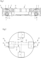
- Figure 1 shows a universal joint with a universal joint at both ends.
- Each of the universal joints has a first joint fork 3 and a second joint fork 5.
- the first joint fork 3 is operatively connected to the second joint fork 5 via a cross pin 9.
- a rotary movement is initiated via the first joint fork 3
- a rotary movement is transmitted to the second joint fork 5 and vice versa.
- the axial axis of the first joint fork 3 can be arranged at an angle to the axial axis of the second joint fork 5. This angle is referred to as the deflection angle.
- the simple universal joint 7 when it runs at a deflection angle, creates a non-uniformity, ie on the drive side it is subjected to It is driven at a constant speed rotating around its axial axis, but on the output side it sometimes rotates a little faster and sometimes a little slower than the drive side.
- the irregularity increases with the bending angle.
- the joint fork which only performs a rotational movement around its axial axis when installed, is referred to as the non-bent joint part 4 or joint fork.
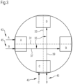
- the universal joint 7 has radial bearings 15 and axial bearings 13.
- the radial bearings 15 support the journal ends 11 radially in relation to the center axis of the journal cross 9.
- the journals of the journal cross 9 are supported axially by the axial bearings 13.
- this axial bearing 13 is provided at the end of the journal end 11.
- the bearings of the ends of the journal cross 9 are shown in a very simplified manner and are labeled A, B, C and D.
- a first lubricant supply 43 and a second lubricant supply 45 are assigned to a journal crossing A.
- the bearings of this journal end are supplied with lubricant by the first lubricant supply 43. This allows new lubricant to be introduced and older lubricant to be pressed out of the bearing by the new lubricant. This also makes it possible to replace lubricant.
- the excess lubricant exits again at a lubricant outlet 51.
- the second lubricant supply 45 is connected to the bearing B via a first passage 37.
- Lubricant can be supplied to the bearing B via this first passage 37.
- the first passage 37 is angled in this embodiment and the bearing B is arranged at a 90° angle to the bearing A.
- lubrication of the Bearings C and D are provided.
- a first lubricant supply 43 is provided for the lubrication of the bearings arranged there.
- Bearing D is supplied with lubricant via a second feedthrough 39.
- the lubricant supplies are provided at two opposite ends of the journal cross. This makes it possible to provide a connection to a centrally arranged lubricant supply when the joint fork 3 is not bent.
- Lubricant can be supplied to each bearing A, B, C, D from this central lubricant supply.
- Each bearing A, B, C, D is assigned its own lubricant supply 41. This makes it possible to supply each bearing with lubricant in an adapted manner. This means that each bearing can be supplied with lubricant in accordance with its actual requirements.
- the advantage is that when the universal joint shaft is at a standstill, the universal joint shaft can be positioned in a targeted manner in which the central lubrication is easily accessible. Lubrication of the bearings is provided when the shaft is at a standstill. However, lubrication can also take place during operation via a rotary feedthrough.
- FIG 3 an alternative design is shown.
- two pin ends are each assigned two lubricant feeds.
- the lubricant feeds 41 are arranged at an angle of 90°. This makes it possible to lubricate all the bearings of this universal joint when the universal joint 7 is at a standstill without having to switch to the other side of the universal joint and thus the universal shaft.
- first passage 37 for bearing B in the journal cross is designed to be straight.
- the second passage 39 for bearing D is also designed to be straight.
- the first center axis 31 and the second center axis 33 of the journal cross 9 are shown in dashed lines.
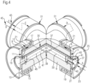
- FIG 4 the structure of a cross member with bearings is shown in detail.
- the cross member 9 is made in one piece.
- a central recess 47 is formed in the cross member.
- the center axes 31 and 33 of the cross member are shown in dashed lines.
- This central recess 47 is closed at the end by an inner cover 27.
- a closure plate 49 is arranged within the central recess in each end of the pin, so that a gap exists between the inner cover 27 and the closure plate 49.
- a lubricant feed 45 is formed in the inner cover 27. When lubricant is applied, the lubricant enters the gap between the inner cover 27 and the closure plate 49. From there, the lubricant enters the lubricant feed 41 formed in the cross member.
- the lubricant enters the first passage 37.
- the passage is according to Figure 2 angled.
- the lubricant reaches the associated bearing B via this passage.
- the lubricant is guided via the radial bearing 15 of the bearing B to the axial bearing 13.
- the lubricant can exit again through the axial bearing at the lubricant outlet 51. This also allows a partial replacement of the lubricant by introducing lubricant until almost no lubricant comes out again at the lubricant outlet 51 without any contamination.
- the radial bearing 15 is designed as a rolling bearing with rolling elements 17.
- the rolling elements 17 are arranged between an inner bearing element 19 and an outer bearing element 21.
- the inner bearing element 19 and the outer bearing element 21 are arranged coaxially to the journal.
- An outer cover 25 is arranged at the axial end. This outer cover 25 is secured by a locking ring 23 in the recess of the joint fork. As can be seen in particular from this illustration, only a few components are required in order to be able to lubricate two bearings from one journal end.
Landscapes
- Engineering & Computer Science (AREA)
- General Engineering & Computer Science (AREA)
- Mechanical Engineering (AREA)
- Rolling Contact Bearings (AREA)
Description
- Die Erfindung betrifft ein Verfahren und eine Vorrichtung zum Schmieren eines Kreuzgelenkes.
- Es ist aus der
EP 0 878 657 A2 eine Schmiervorrichtung für eine Gelenkwelle mit einem Kreuzgelenk bekannt. Das Kreuzgelenk weist eine Gelenkgabel und ein Kreuzgelenk mit schmierbaren Lagern auf. Es ist ein gehäusefestes Bauteil vorgesehen, durch das der Schmierstoff zur Gelenkwelle und durch diese hindurch mittels eines Übertragungselementes zu den Gelenklagern geführt wird. Dadurch erfolgt die Schmierung von einem stationären Bauteil aus, dass eine Schmierung unabhängig von der Bewegung der Gelenkwelle erfolgen kann. Die Schmierstelle ist leicht zugänglich und zum Anschluss an eine Zentralschmierung geeignet. - Aus der
US 3,337,820 ist ein Kreuzgelenk mit Lagern bekannt. Die Lager des Kreuzgelenkes können gleichzeitig geschmiert werden. Es ist eine äußere Zuführung für Schmiermittel vorgesehen. Durch diese äußere Zuführung werden Kreuzpassagen mit Schmiermittel beaufschlagt. Diese Schmiermittelpassagen sind innerhalb des Kreuzes mittig angeordnet und mit den Lagern verbunden. Durch Kanäle kann das alte Schmiermittel aus dem Kreuzgelenk an einer Dichtung vorbei aus dem Kreuzgelenk herausgedrückt werden. Dieser Anordnung lag die Aufgabe zugrunde für eine Erhöhung der Lebensdauer die Lager mit frischem sauberem Schmiermittel zu fluten und dadurch gebrauchtes Schmiermittel mit Fremdpartikeln zu entfernen. - Aus der
US 3,828,578 ist ebenfalls ein Kreuzgelenk mit einem zentral angeordneten kreuzförmigen Schmierkanal bekannt. Dieser Schmierkanal kann mit Schmiermittel über einen Einlass beaufschlagt werden. Diesem Patent lag die Aufgabe zu Grunde die Schmierung zu verbessern. Am Kreuzungspunkt der Schmierkanäle in der Mitte des Kreuzelementes des Kreuzgelenkes ist ein drehbares Element für eine Schmiermittelverteilung vorgesehen. - Aus der
CN 103775519 A ist ein Kreuzgelenk mit zentral im Kreuzelement verlaufenden Ölkanälen bekannt. angeordneten Schmierkanälen bekannt. An den Enden des Kreuzgelenkes sind Einlässe und ein Reservoir für die Aufnahme von Schmiermittel vorgesehen. Über die Schmierkanäle sind die Reservoirs miteinander verbunden, so dass auch bei einer verstopften Injektionszuführung eine Schmierung der Lager sichergestellt ist. - Aus der
CN 202660200 U ist eine Schmiervorrichtung für ein Kreuzgelenk bekannt. Durch diese Schmiervorrichtung ist eine Online-Schmierung möglich. Für die Bereitstellung des Schmiermittels ist auf der Gelenkwelle ein rotierender Ring mit einer Düse bekannt. Es sind zwei Zuführungen zu jeder Seite der Gelenkgabel gezeigt. - Aus der
CN 20445885 U ist es bekannt, einer Kreuzwelle eines Kreuzgelenkes für jedes Lager eine separate Schmiereinrichtung vorzusehen. Dafür wird die Kreuzverbindung in der Kreuzwelle des Kreuzgelenkes verschlossen. - Aus der
DE 10 2016 210 587 ist eine Kreuzgelenkanordnung bekannt, bei dem die Lager des Kreuzgelenkes durch eine zentral in jedem der Lagerdeckel ausgebildete Öffnung mit Schmiermittel geschmiert werden können. Dafür ist es jedoch erforderlich, dass von jedem Deckel aus ein Schmieren erfolgt. In einigen Einbausituationen sind die Kreuzgelenke nicht von allen Seiten gleich gut zugänglich. Somit kommt es häufiger vor, dass die gut zugänglichen Schmiermittelzugänge bevorzugt bedient werden und die schwer zugänglichen Schmiermittelzugänge schon mal ausgelassen werden. Dadurch treten an den nicht ausreichend geschmierten Lagerungen vermehrt Schäden auf. Auch kann ein Positionswechsel von einer der Seiten der Gelenkwelle auf die gegenüberliegende Seite der Gelenkwelle für das Schmieren unkomfortabel sein, so dass manchmal nur die von einer der Seiten der Gelenkwelle zugänglichen Deckeln mit den Schmiermittelöffnungen mit Schmiermittel beaufschlagt werden. Auch dadurch können vermehrt Defekte an den unzureichend geschmierten Lagerungen entstehen. -
JP2006002845 A -
SU525567 A1 - Nachteilig ist bei den bekannten Schmiervorrichtungen, dass diese kostenintensiv schon allein aufgrund der Teilezahl ist. Weiterhin kommt hinzu, dass die mitrotierenden Teile der Schmiervorrichtung mit beschleunigt werden müssen und somit auch den Beschleunigungen standhalten müssen.
- Der Erfindung liegt die Aufgabe zu Grunde, eine Schmierung eines Kreuzgelenkes komfortabler zu ermöglichen.
- Insbesondere ist es die Aufgabe der Erfindung die Zugänglichkeit zur Schmierung von Lagerungen eines Kreuzgelenkes in einer diskreten Stillstandsposition zu erleichtern.
- Die Aufgabe der Erfindung wird dadurch gelöst, dass in dem Zapfenkreuz mindestens eine Durchführung für Schmiermittel ausgebildet ist. Die Durchführung ist für die Zuführung von Schmiermittel zu einer der Lagerungen vorgesehen. Durch die Durchführung ist es möglich, eine Lagerung eines Zapfenkreuzendes zu schmieren, wobei die Lagerung in einem Winkel von 90° oder 180° angeordnet sein kann. Die Durchführung dient dabei der Zuführung von Schmiermittel. Somit ist es möglich, die diesem Zapfenende zugeordnete Lagerung und eine weitere Lagerung mittels der Durchführung mit Schmiermittel zu versorgen. Dabei können beide Lagerungen getrennt voneinander mit Schmiermittel beaufschlagt werden. Dadurch ist es auch möglich, den Druck, mit dem das Schmiermittel zugeführt wird, für jeden Schmiervorgang und abhängig von der Art der Zuführung bzw. der Position des zu schmierenden Lagers zu wählen.
- In der Regel umfasst eine Lagerung eines Zapfenendes eines Zapfenkreuzes ein Axiallager und ein Radiallager.
- Erfindungsgemäß ist die Durchführung in dem Zapfenkreuz beabstandet zu mindestens einer der Mittenachsen des Zapfenkreuzes ausgebildet. Besonders bevorzugt ist die Durchführung zumindestens auf einem Teilbereich parallel zur Mittenachse angeordnet. Es ist somit eine Anordnung einer Durchführung innerhalb einer im Zapfenkreuz vorhandenen Zentralausnehmung möglich. Um den möglichen Beschleunigungen standhalten zu können ist eine stabile Befestigung erforderlich.
- Erfindungsgemäß weist das Zapfenkreuz mindestens zwei getrennte Durchführungen für Schmiermittel auf. Diese Durchführungen können für die Beaufschlagung mit Schmiermittel genutzt werden. Damit ist es möglich von zwei Kreuzgelenkenden aus alle vier Lagerungen zu schmieren, indem zwei der Lagerungen mittels der ersten und der zweiten Durchführung Schmiermittel beaufschlagt werden können.
- Bei einer bevorzugten Ausführungsform eines Zapfenkreuzes sind vorzugsweise zwei der Schmiermitteldurchführungen in einem Winkel von 90° angeordnet. Jede einzelne Durchführung kann geradlinig oder gewinkelt ausgeführt sein.
- Bei einer bevorzugten Ausführungsform ist vorgesehen, dass die Durchführung parallel zu einer der Mittenachsen angeordnet ist. Dadurch sind die Durchführungen geradlinig ausgeführt, was sich leicht fertigen lässt. Um alle Lager damit erreichen zu können sind die beiden Durchführungen bevorzugt in einem 90° Winkel zueinander versetzt angeordnet.
- In einer weiteren Ausführungsform ist vorgesehen, dass mindestens eine Durchführung mit dem Zapfenkreuz einstückig ausgebildet ist. Damit ist gemeint, dass in dem Zapfenkreuz keine Bauteile eingebraucht sind, um die Durchführung bereitzustellen. Eine derartige Durchführung kann mittels einer Bohrung ausgebildet werden.
- In einer bevorzugten Ausführungsform ist vorgesehen, dass Öffnungen von Durchführungen für Schmiermittel an zwei gegenüberliegenden Zapfenenden angeordnet sind und mittels dieser Durchführungen alle Axiallager schmierbar sind. Die Durchführungen müssen winkelig ausgeführt sein.
- Erfindungsgemäß umfasst das Kreuzgelenk eine erste Gelenkgabel und eine zweite Gelenkgabel und ein Zapfenkreuz mit Zapfenkreuzenden, wobei Enden des Zapfenkreuzes in der ersten und der zweiten Gelenkgabel gelagert sind.
- Erfindungsgemäß umfasst das Kreuzgelenk ein Zapfenkreuz. Dadurch ist es möglich mit einem verminderten Aufwand die Lager des Kreuzgelenkes zu schmieren. Es können mindestens von einer Gelenkgabelseite zwei Lager geschmiert werden. Es ist möglich eine Stillstandsposition vorzusehen, bei der von einer Gelenkgabelseite zumindestens eine schwer zugängliche Lagerung des Kreuzgelenkes mittels einer Durchführung mit Schmiermittel beaufschlagt werden kann.
- In einer bevorzugten Ausführungsform eines Kreuzgelenkes ist vorgesehen, dass das Kreuzgelenk an zwei gegenüberliegenden Seiten jeweils zwei Schmiermittelzuführungen aufweist, wobei jede Schmiermittelzuführung genau einem Lager zugeordnet ist. Dadurch ist es möglich von diesen beiden Seiten alle Lagerungen des Kreuzgelenkes zu schmieren. Es ist insbesondere auch möglich bei einem nicht gebeugten Einbau vorzusehen, dass die Schmiermittelzuführung auf der nur rotierenden Gelenkgabel angerordnet ist. Durch Zuleitungen kann dann Schmiermittel von einer zentralen Schmiermittelzuführung den Schmiermittelzuführungen zugeführt werden. Durch die zentrale Schmiermittelzuführung können alle Lagerungen getrennt mit Schmiermittel beaufschlagt werden. Diese zentrale Schmiermittelzuführung kann auf der Gelenkgabel oder Gelenkwelle angeordnet sein. Damit ist ein Abschmieren besonders komfortabel durchführbar ohne dass ein Positionswechsel erforderlich ist.
- In einer bevorzugten Ausführungsform eines Kreuzgelenkes ist vorgesehen, dass an zwei in einem Winkel von 90° angeordneten Positionen des Kreuzgelenkes vorgesehene Zuführungen für Schmiermittel vorgesehen sind, die vorzugsweise in vorgesehenen Deckel ausgebildet sind. Dadurch ist es komfortabel möglich in einer Stillstandsposition von einer Seite des Kreuzgelenkes alle Lagerungen des Kreuzgelenkes zu schmieren.
- In einer weiteren Ausführungsform ist vorgesehen, dass das Kreuzgelenk vier Gelenkdeckel umfasst und Schmiermittelzuführungen nur in einem der Deckel ausgebildet sind. Das Zapfenkreuz weist drei Durchführungen auf, so dass den anderen Zapfenkreuzenden Schmiermittel durch die Durchführungen zugeführt werden kann
Es hat sich als vorteilhaft herausgestellt, eine Gelenkwelle mit einem erfindungsgemäßen Kreuzgelenk zu versehen. Dabei hat sich als besonders vorteilhaft herausgestellt die Schmiermittelzuführungen an gegenüberliegenden Zapfenenden vorzusehen. Dabei kann bei nicht gebeugtem Einbau eine zentrale Schmiermittelzuführung auf der Gelenkwelle angeordnet werden. Die zentrale Schmiermittelzuführung umfasst einzelne den einzelnen Lagerungen zugeordnete Schmiermittelzuführungen. - Ein erfindungsgemäßen Verfahren zum Abschmieren von Lagerungen einer Gelenkwelle, insbesondere von Radiallagern und Axiallager, eines Kreuzgelenkes, zeichnet sich dadurch aus, dass eine Stillstandsposition eingenommen wird und anschließend die einzelnen Lagerungen getrennt voneinander mit Schmiermittel beaufschlagt werden. Dadurch kann die Schmiermitteldosierung für jede Lagerung individuell dosiert werden. Bei der Schmiermitteldosierung kann das Schmiermittel mit unterschiedlichen Drücken beaufschlagt werden. Außerdem kann die Menge an eingebrachtem Schmiermittel individuell dosiert werden und somit sichergestellt werden, dass ausreichend geschmiert wurde.
- Die erfindungsgemäße Lösung wird nachfolgend anhand einiger Ausführungsbeispiele näher beschrieben. Die gezeigten Ausführungsbeispiele können eigenständige erfinderische Aspekte beinhalten.
- Es zeigt:
- Figur 1:
- Gelenkwelle
- Figur 2:
- Skizzierung von Schmiermittelzuführungen gegenüberliegend
- Figur 3:
- Skizzierung von Schmiermittelzuführungen im 90° Winkel
- Figur 4:
- Zapfenkreuz
-
Figur 1 zeigt eine Gelenkwelle mit einem Kreuzgelenk an beiden Enden. Jedes der Kreuzgelenke weist eine erste Gelenkgabel 3 und eine zweite Gelenkgabel 5 auf. Die erste Gelenkgabel 3 ist über ein Zapfenkreuz 9 mit der zweiten Gelenkgabel 5 wirkverbunden. Bei Einleitung einer Drehbewegung über die erste Gelenkgabel 3 wird eine Drehbewegung auf die zweite Gelenkgabel 5 übertragen und umgekehrt. Dabei kann die Axialachse der ersten Gelenkgabel 3 winkelig zur Axialachse der zweiten Gelenkgabel 5 angeordnet sein. Dieser Winkel wird als Beugewinkel bezeichnet. Das einfache Kreuzgelenk 7 erzeugt, wenn es unter Beugewinkel läuft, eine Ungleichförmigkeit, d.h. auf der Antriebsseite wird es mit konstanter Drehzahl rotierend um dessen Axialachse angetrieben, aber auf der Abtriebsseite dreht es sich mal ein bisschen schneller und mal ein bisschen langsamer als die Antriebsseite. Die Ungleichförmigkeit nimmt mit dem Beugewinkel zu. Die Gelenkgabel, die in eingebautem Zustand nur eine Rotationsbewegung um seine Axialachse ausführt, wird als nicht gebeugtes Gelenkteil 4 bzw. Gelenkgabel bezeichnet. - In
Figur 2 sind Durchführungen für eine Schmierung von Lagern 12 des Kreuzgelenkes 7 gezeigt. Das Kreuzgelenk 7 weist Radiallager 15 und Axiallager 13 auf. Durch die Radiallager 15 sind die Zapfenenden 11 radial in Bezug auf die Mittenachse des Zapfenkreuzes 9 gelagert. Durch die Axiallager 13 sind die Zapfen des Zapfenkreuzes 9 axial gelagert. In dem gezeigten Ausführungsbeispiel ist dieses Axiallager 13 endseitig am Zapfenende 11 vorgesehen. - Bei dem gezeigten Ausführungsbeispiel sind die Lagerungen der Enden des Zapfenkreuzes 9 sehr vereinfacht dargestellt und mit A, B, C und D bezeichnet. Bei diesem Ausführungsbeispiel ist einem Zapfen kreuzende A eine erste Schmiermittelzuführung 43 und eine zweite Schmiermittelzuführung 45 zugeordnet. Durch die erste Schmiermittelzuführung 43 werden die Lager dieses Zapfenendes mit Schmiermittel beaufschlagt. Dadurch kann zum einen neues Schmiermittel eingebracht werden und auch älteres Schmiermittel aus dem Lager durch das neue Schmiermittel herausgedrückt werden. Somit ist auf diese Weise auch ein Austausch von Schmiermittel möglich. Der Schmiermittelüberschuss tritt an einem Schmiermittelaustritt 51 wieder aus.
- Die zweite Schmiermittelzuführung 45 ist über eine erste Durchführung 37 mit der Lagerung B verbunden. Über diese erste Durchführung 37 kann Schmiermittel der Lagerung B zugeführt werden. Die erste Durchführung 37 ist in diesem Ausführungsbeispiel gewinkelt ausgeführt und die Lagerung B ist in einem 90° Winkel zu der Lagerung A angeordnet. In gleicher Weise ist eine Schmierung der Lagerungen C und D vorgesehen. Dabei ist wiederum eine erste Schmiermittelzuführung 43 für die Schmierung für die dort angeordneten Lager vorgesehen. Die Lagerung D wird über eine zweite Durchführung 39 mit Schmiermittel versorgt. In diesem Ausführungsbeispiel sind die Zuführungen für Schmiermittel an zwei gegenüberliegenden Enden des Zapfenkreuzes vorgesehen. Dadurch ist es möglich bei einer nicht gebeugten Anordnung der Gelenkgabel 3, eine Verbindung zu einer zentral angeordneten Schmiermittelzuführung vorzusehen. Von dieser zentralen Schmiermittelzuführung können jeder Lagerung A, B, C, D Schmiermittel zugeführt werden. Dabei ist jeder Lagerung A, B, C, D eine eigene Schmiermittelzuführung 41 zugeordnet. Dadurch ist es möglich jedes Lager angepasst mit Schmiermittel zu beaufschlagen. Dadurch kann jede Lagerung abgestimmt an den tatsächlichen Bedarf mit Schmiermittel versorgt werden. Der Vorteil ist aber, dass bei einem Stillstand der Gelenkwelle, die Gelenkwelle gezielt in eine Position positioniert werden kann, bei der die zentrale Schmierung leicht zugänglich ist. Eine Schmierung der Lager ist bei Stillstand vorgesehen. Die Schmierung kann allerdings auch im Betrieb über eine Drehdurchführung erfolgen.
- In
Figur 3 ist eine alternative Ausführung gezeigt. Bei dieser Ausführung sind zwei Zapfenenden jeweils zwei Schmiermittelzuführungen zugeordnet. Die Schmiermittelzuführungen 41 sind in einem Winkel von 90° angeordnet. Dadurch ist es möglich ohne einen Wechsel auf die andere Seite des Kreuzgelenkes und damit der Gelenkwelle, alle Lager dieses Kreuzgelenkes bei Stilstand des Kreuzgelenkes 7 zu schmieren. - Bei dieser Ausführung ist die erste Durchführung 37 zur Lagerung B im Zapfenkreuz geradlinig ausgebildet. Die zweite Durchführung 39 zur Lagerung D ist auch geradlinig ausgeführt. Die erste Mittenachse 31 und die zweite Mittenachse 33 des Zapfenkreuzes 9 sind gestrichelt dargestellt.
- In
Figur 4 ist der Aufbau eines Zapfenkreuzes mit Lagern detailliert dargestellt. Das Zapfenkreuz 9 ist einteilig ausgeführt. In dem Zapfenkreuz ist eine Zentralausnehmung 47 ausgebildet. Die Mittenachsen 31, und 33 des Zapfenkreuzes sind gestrichelt dargestellt. Diese Zentralausnehmung 47 ist endseitig durch einen inneren Deckel 27 verschlossen. Innerhalb der Zentralausnehmung ist in jedem Zapfenenden eine Verschlussplatte 49 angeordnet, so dass ein Spalt zwischen innerem Deckel 27 und Verschlussplatte 49 besteht. In dem inneren Deckel 27 ist eine Schmiermittelzuführung 45 ausgebildet. Bei Beaufschlagung mit Schmiermittel gelangt das Schmiermittel in den Spalt zwischen innerem Deckel 27 und Verschlussplatte 49. Von dort gelangt das Schmiermittel in die in dem Zapfenkreuz ausgebildete Schmiermittelzuführung 41. In dem konkreten Ausführungsbeispiel gelangt das Schmiermittel in die erste Durchführung 37. Die Durchführung ist gemäßFigur 2 gewinkelt ausgeführt. Über diese Durchführung gelangt das Schmiermittel zur zugeordneten Lagerung B. In der Lagerung B wird das Schmiermittel über das Radiallager 15 der Lagerung B zum Axiallager 13 geleitet. Durch das Axiallager kann das Schmiermittel am Schmiermittelaustritt 51 wieder austreten. Dadurch kann auch ein teilweiser Austausch des Schmiermittels durchgeführt werden, indem solange Schmiermittel eingeführt wird, bis am Schmiermittelaustritt 51 wieder nahezu Schmiermittel ohne Verunreinigungen austritt. - Das Radiallager 15 ist als Wälzlager mit Wälzkörpern 17 ausgeführt. Die Wälzkörper 17 sind zwischen einem inneren Lagerelement 19 und einem äußeren Lagerelement 21 angeordnet. Das innere Lagerelement 19 und das äußere Lagerelement 21 sind koaxial zum Zapfen angeordnet. Axial endseitig ist ein äußerer Deckel 25 angeordnet. Dieser äußere Deckel 25 wird durch einen Sicherungsring 23 in der Ausnehmung der Gelenkgabel gesichert. Wie insbesondere aus dieser Darstellung ersichtlich wird, werden nur wenige Bauteile benötigt, um von einem Zapfenende aus zwei Lagerungen schmieren zu können.
-
- 1
- Gelenkwelle
- 3
- Erste Gelenkgabel
- 4
- nicht gebeugtes Gelenkteil
- 5
- Zweite Gelenkgabel
- 6
- gebeugtes Gelenkteil
- 7
- Kreuzgelenk
- 9
- Zapfenkreuz
- 11
- Enden Zapfenkreuz
- 12
- Lagerung, Lager gesamt
- 13
- Axiallager
- 15
- Radiallager
- 17
- Wälzkörper
- 19
- Inneres Lagerelement
- 21
- Äußeres Lagerelement
- 23
- Sicherungsring
- 25
- Äußerer Deckel
- 27
- Innerer Deckel
- 31
- Erste Mittenachse
- 33
- Zweite Mittenachse
- 35
- Durchführung für Schmiermittel
- 37
- Erste Durchführung
- 39
- Zweite Durchführung
- 41
- Schmiermittelzuführung
- 43
- Erste Schmiermittelzuführung
- 45
- Zweite Schmiermittelzuführung
- 47
- Zentralausnehmung Zapfenkreuz
- 49
- Verschlussplatte
- 51
- Schmiermittelaustritt
- 61
- Zentrale Schmiermittelzuführung
Claims (10)
- Kreuzgelenk (7) mit einer ersten Gelenkgabel (3) und einer zweiten Gelenkgabel (5) und mit einem Zapfenkreuz (9), wobei Enden (11) des Zapfenkreuzes (9) in der ersten (3) und der zweiten Gelenkgabel (5) gelagert sind, dass das Zapfenkreuz (9) zwei getrennte Durchführungen (37, 39), für Schmiermittel aufweist, wobei jede Durchführung (37, 39) für die Zuführung von Schmiermittel zu genau einer einem Zapfenende (11) zugeordneten Lagerung (A, B, C, D) vorgesehen ist, wobei das Zapfenkreuz (9) beabstandet von mindestens einer der Mittenachsen (31, 33) eine der Durchführungen (37, 39) für Schmiermittel aufweist,
dadurch gekennzeichnet, dass
an zwei gegenüberliegenden Seiten des Kreuzgelenkes (7) das Kreuzgelenk (7) jeweils zwei Schmiermittelzuführungen (43, 45) aufweist, wobei jede Schmiermittelzuführung (43, 45) genau einer Lagerung (A, B, C, D) zugeordnet ist, oder dass an zwei in einem Winkel von 90° angeordneten Positionen des Kreuzgelenkes (9) vorgesehene Zuführungen (41) für Schmiermittel vorgesehen sind, dabei ist jeder Lagerung A, B, C, D eine eigene Schmiermittelzuführung (41) zugeordnet. - Kreuzgelenk (7) nach Anspruch 1,
dadurch gekennzeichnet,
dass mindestens eine vorzugsweise zwei der Schmiermitteldurchführungen (37, 39) einen 90° Winkel aufweist. - Kreuzgelenk (7) nach Anspruch 1 oder Anspruch 2,
dadurch gekennzeichnet,
dass die Durchführung (37, 39) parallel zu einer der Mittenachsen (31, 33) angeordnet ist. - Kreuzgelenk (7) nach einem der vorhergehenden Ansprüche,
dadurch gekennzeichnet,
dass mindestens eine Durchführung (37, 39) mit dem Zapfenkreuz (9) einstückig ausgebildet ist. - Kreuzgelenk (7) nach einem der vorhergehenden Ansprüche,
dadurch gekennzeichnet,
dass Öffnungen von Durchführungen (37, 39) für Schmiermittel an zwei gegenüberliegenden Zapfenenden (11) angeordnet sind und mittels dieser Durchführungen (37, 39) alle Lagerungen (12), insbesondere alle Axiallager (13) und Radiallager (15), schmierbar sind. - Kreuzgelenk (7) nach einem der vorhergehenden Ansprüche,
dadurch gekennzeichnet,
dass nur in einem einem Zapfen des Zapfenkreuzes (9) einem zugeordneten Gelenkdeckel (25, 27) eine Schmiermittelzuführung (41) ausgebildet ist. - Gelenkwelle mit einem Kreuzgelenk (7) nach einem der vorhergehenden Ansprüche,
dadurch gekennzeichnet,
dass auf der Gelenkwelle (1) oder einer der Gelenkgabel (3) eine zentrale Schmiermittelzuführung (61) vorgesehen ist und diese Schmiermittelzuführung (61) mit den den Zapfenenden (11) zugeordneten Zuführungen (43, 45) verbunden ist. - Gelenkwelle nach Anspruch 7,
dadurch gekennzeichnet,
dass die zentrale Schmiermittelzuführung (61) auf einer nicht gebeugten Gelenkgabel (3) oder Gelenkwelle (1) angeordnet ist. - Verfahren zum Abschmieren von Lagern (12) eines Kreuzgelenkes (7) nach einem der vorhergehenden Ansprüche,
dadurch gekennzeichnet,
dass ein Schmieren der Lagerungen (12) im Stillstand vorgesehen ist. - Verfahren nach Anspruch 9,
dadurch gekennzeichnet,
dass die mit den Verfahrensschritten:- Im Stillstand des Kreuzgelenkes (7) wird Schmiermittel von zwei Enden (11) des Zapfenkreuzes (7) zugeführt, wobei jede Lagerung eines Zapfens einzeln mit Schmiermittel beaufschlagt wird bis Schmiermittel an dem Schmiermittelaustritt (51) dieser Lagerung (A, B, C, D) austritt.
Applications Claiming Priority (2)
| Application Number | Priority Date | Filing Date | Title |
|---|---|---|---|
| DE102017122107.7A DE102017122107A1 (de) | 2017-09-25 | 2017-09-25 | Verfahren und Vorrichtung zum Schmieren eines Kreuzgelenkes |
| PCT/EP2018/073324 WO2019057462A1 (de) | 2017-09-25 | 2018-08-30 | Verfahren und vorrichtung zum schmieren eines kreuzgelenkes |
Publications (2)
| Publication Number | Publication Date |
|---|---|
| EP3688331A1 EP3688331A1 (de) | 2020-08-05 |
| EP3688331B1 true EP3688331B1 (de) | 2024-08-21 |
Family
ID=63528719
Family Applications (1)
| Application Number | Title | Priority Date | Filing Date |
|---|---|---|---|
| EP18766156.6A Active EP3688331B1 (de) | 2017-09-25 | 2018-08-30 | Verfahren und vorrichtung zum schmieren eines kreuzgelenkes |
Country Status (6)
| Country | Link |
|---|---|
| US (1) | US11578763B2 (de) |
| EP (1) | EP3688331B1 (de) |
| JP (1) | JP7216081B2 (de) |
| CN (1) | CN111148916B (de) |
| DE (1) | DE102017122107A1 (de) |
| WO (1) | WO2019057462A1 (de) |
Families Citing this family (4)
| Publication number | Priority date | Publication date | Assignee | Title |
|---|---|---|---|---|
| DE102019122050A1 (de) * | 2019-08-16 | 2021-02-18 | Voith Patent Gmbh | Gelenkwellengelenk, Gelenkwelle und Verfahren zum Schmieren von Lagern in einem Gelenkwellengelenk |
| JP2022013639A (ja) * | 2020-07-01 | 2022-01-18 | 株式会社ジェイテクト | ドライブシャフト |
| CN113883180A (zh) * | 2020-07-01 | 2022-01-04 | 株式会社捷太格特 | 驱动轴 |
| JP7615832B2 (ja) * | 2021-03-29 | 2025-01-17 | 株式会社Ihi | ローラタイヤアセンブリ |
Citations (2)
| Publication number | Priority date | Publication date | Assignee | Title |
|---|---|---|---|---|
| SU525567A1 (ru) * | 1974-12-13 | 1976-08-25 | Предприятие П/Я Р-6131 | Крестовина карданного шарнира |
| JP2006002845A (ja) * | 2004-06-17 | 2006-01-05 | Koyo Seiko Co Ltd | 十字軸継手及び十字軸 |
Family Cites Families (17)
| Publication number | Priority date | Publication date | Assignee | Title |
|---|---|---|---|---|
| US1306229A (en) * | 1919-06-10 | -myers | ||
| US3377820A (en) | 1966-09-07 | 1968-04-16 | Cleveland Steel Products Corp | Universal joint seal |
| US3828578A (en) * | 1973-05-10 | 1974-08-13 | Deere & Co | U-joint lubrication spider |
| US4047396A (en) * | 1976-05-13 | 1977-09-13 | Rockwell International Corporation | Universal joint and cross therefor |
| JPS5653150Y2 (de) * | 1977-04-12 | 1981-12-11 | ||
| USRE30790E (en) * | 1979-03-22 | 1981-11-10 | The Zeller Corporation | Universal joint lubrication |
| SU889936A1 (ru) * | 1980-01-23 | 1981-12-15 | Институт проблем надежности и долговечности машин АН БССР | Крестовина карданного шарнира |
| JPS59194133A (ja) * | 1983-04-20 | 1984-11-02 | Koyo Seiko Co Ltd | ユニバ−サルジヨイントの潤滑剤供給装置 |
| US5342240A (en) * | 1989-07-12 | 1994-08-30 | The Zeller Corporation | High capacity universal joint |
| US5263552A (en) * | 1992-07-06 | 1993-11-23 | The Cline Company | Automatic lubrication system for an industrial rotary drive |
| DE19720950A1 (de) | 1997-05-17 | 1998-11-19 | Same Deutz Fahr Spa | Schmiervorrichtung |
| JP5271178B2 (ja) * | 2009-07-10 | 2013-08-21 | 株式会社中村自工 | 自在継手の十字軸 |
| CN202660200U (zh) | 2012-06-29 | 2013-01-09 | 江苏申久化纤有限公司 | 一种用于万向轴轴承的在线加油装置 |
| CN103775519A (zh) * | 2014-03-03 | 2014-05-07 | 贵阳力波机械传动有限公司 | 万向联轴器无滚针重载十字轴 |
| CN204458885U (zh) | 2014-12-01 | 2015-07-08 | 长春轨道客车股份有限公司 | 独立注油式万向轴十字单元包结构 |
| DE102016210587A1 (de) | 2016-06-15 | 2017-12-21 | Voith Patent Gmbh | Gelenkanordnung für eine Gelenkwelle |
| JP6939673B2 (ja) * | 2018-03-23 | 2021-09-22 | トヨタ自動車株式会社 | 車両の十字軸継手 |
-
2017
- 2017-09-25 DE DE102017122107.7A patent/DE102017122107A1/de not_active Withdrawn
-
2018
- 2018-08-30 JP JP2020517148A patent/JP7216081B2/ja active Active
- 2018-08-30 CN CN201880061638.2A patent/CN111148916B/zh active Active
- 2018-08-30 WO PCT/EP2018/073324 patent/WO2019057462A1/de not_active Ceased
- 2018-08-30 US US16/650,442 patent/US11578763B2/en active Active
- 2018-08-30 EP EP18766156.6A patent/EP3688331B1/de active Active
Patent Citations (2)
| Publication number | Priority date | Publication date | Assignee | Title |
|---|---|---|---|---|
| SU525567A1 (ru) * | 1974-12-13 | 1976-08-25 | Предприятие П/Я Р-6131 | Крестовина карданного шарнира |
| JP2006002845A (ja) * | 2004-06-17 | 2006-01-05 | Koyo Seiko Co Ltd | 十字軸継手及び十字軸 |
Also Published As
| Publication number | Publication date |
|---|---|
| CN111148916A (zh) | 2020-05-12 |
| JP7216081B2 (ja) | 2023-01-31 |
| DE102017122107A1 (de) | 2019-03-28 |
| US11578763B2 (en) | 2023-02-14 |
| US20200271169A1 (en) | 2020-08-27 |
| JP2020535356A (ja) | 2020-12-03 |
| EP3688331A1 (de) | 2020-08-05 |
| WO2019057462A1 (de) | 2019-03-28 |
| CN111148916B (zh) | 2022-12-06 |
Similar Documents
| Publication | Publication Date | Title |
|---|---|---|
| EP3688331B1 (de) | Verfahren und vorrichtung zum schmieren eines kreuzgelenkes | |
| DE2804811A1 (de) | Vorrichtung zur langzeitschmierung von lagerelementen | |
| EP2960201A1 (de) | Drehverteiler zum verteilen von fliessfähigen medien | |
| DE1625893C2 (de) | Axialgleitlager | |
| DE102015215296B4 (de) | Lageranordnung und Lagerring zum drehbeweglichen Lagern eines ersten Bauteils gegenüber einem zweiten Bauteil sowie Schraubenkompressor mit der Lageranordnung oder dem Lagerring | |
| DE102007039523B4 (de) | Vorrichtung an einer Strecke mit einem Streckwerk für Textilfaserbänder | |
| DE102007039522B4 (de) | Vorrichtung an einem Streckwerk einer Strecke für Textilfaserbänder | |
| DE3211715C2 (de) | Druckgeschmierte Wälzlageranordnung für die Welle einer geschlossenen elektrischen Maschine | |
| DE2219720A1 (de) | Lagerschale für ein Wellengelenk, beispielsweise Kreuzgelenk | |
| DE4408552A1 (de) | Oberwalze | |
| DE19960706C2 (de) | Vorrichtung für ein Gehäuse mit Deckel für Radsätze von Schienenfahrzeugen | |
| DE102018206905B4 (de) | Schmierstoffversorgung eines Radialgleitlagers | |
| DE202016103920U1 (de) | Strangführungsrolle zum Führen eines metallischen Strangs in einer Stranggießanlage | |
| EP0031415A1 (de) | Wellenabdichtung für Verreibwalzen in Farbwerken von Druckmaschinen | |
| DE102022118743B4 (de) | Schnelles Schmierfetteinfüllgerät | |
| DE2842794C2 (de) | Flaschentisch für Etikettiermaschinen o.dgl. | |
| EP0443505A1 (de) | Schneidvorrichtung mit Kühlwasserzufuhr zu einem Sägeblatt | |
| DE19830301A1 (de) | Verfahren zur Schmierung der Verzahnung einer Getriebeeinheit | |
| DE20209091U1 (de) | Rollenanordnung für einen Zwirnkopfrotor | |
| DE2224495A1 (de) | Verstellbare halterung fuer selbstschmierende spinn- oder zwirnringe an spinn- oder zwirnmaschinen | |
| EP1895033A2 (de) | Zwirnkopfrotor | |
| DE2449934C3 (de) | Vorrichtung zur Schmiermittelzuführung in die Schmiermittelbohrungen der Achsen von Strangführungsrollen | |
| DE2113905C3 (de) | Lager für Spinnrotoren | |
| DE4111609C1 (de) | ||
| EP1703149A2 (de) | Fluidabgabeeinrichtung für Wellen |
Legal Events
| Date | Code | Title | Description |
|---|---|---|---|
| STAA | Information on the status of an ep patent application or granted ep patent |
Free format text: STATUS: UNKNOWN |
|
| STAA | Information on the status of an ep patent application or granted ep patent |
Free format text: STATUS: THE INTERNATIONAL PUBLICATION HAS BEEN MADE |
|
| PUAI | Public reference made under article 153(3) epc to a published international application that has entered the european phase |
Free format text: ORIGINAL CODE: 0009012 |
|
| STAA | Information on the status of an ep patent application or granted ep patent |
Free format text: STATUS: REQUEST FOR EXAMINATION WAS MADE |
|
| 17P | Request for examination filed |
Effective date: 20200428 |
|
| AK | Designated contracting states |
Kind code of ref document: A1 Designated state(s): AL AT BE BG CH CY CZ DE DK EE ES FI FR GB GR HR HU IE IS IT LI LT LU LV MC MK MT NL NO PL PT RO RS SE SI SK SM TR |
|
| AX | Request for extension of the european patent |
Extension state: BA ME |
|
| DAV | Request for validation of the european patent (deleted) | ||
| DAX | Request for extension of the european patent (deleted) | ||
| STAA | Information on the status of an ep patent application or granted ep patent |
Free format text: STATUS: EXAMINATION IS IN PROGRESS |
|
| 17Q | First examination report despatched |
Effective date: 20210325 |
|
| GRAP | Despatch of communication of intention to grant a patent |
Free format text: ORIGINAL CODE: EPIDOSNIGR1 |
|
| STAA | Information on the status of an ep patent application or granted ep patent |
Free format text: STATUS: GRANT OF PATENT IS INTENDED |
|
| INTG | Intention to grant announced |
Effective date: 20240319 |
|
| GRAS | Grant fee paid |
Free format text: ORIGINAL CODE: EPIDOSNIGR3 |
|
| GRAA | (expected) grant |
Free format text: ORIGINAL CODE: 0009210 |
|
| STAA | Information on the status of an ep patent application or granted ep patent |
Free format text: STATUS: THE PATENT HAS BEEN GRANTED |
|
| AK | Designated contracting states |
Kind code of ref document: B1 Designated state(s): AL AT BE BG CH CY CZ DE DK EE ES FI FR GB GR HR HU IE IS IT LI LT LU LV MC MK MT NL NO PL PT RO RS SE SI SK SM TR |
|
| REG | Reference to a national code |
Ref country code: GB Ref legal event code: FG4D Free format text: NOT ENGLISH |
|
| REG | Reference to a national code |
Ref country code: CH Ref legal event code: EP |
|
| REG | Reference to a national code |
Ref country code: IE Ref legal event code: FG4D Free format text: LANGUAGE OF EP DOCUMENT: GERMAN |
|
| REG | Reference to a national code |
Ref country code: DE Ref legal event code: R096 Ref document number: 502018015042 Country of ref document: DE |
|
| REG | Reference to a national code |
Ref country code: LT Ref legal event code: MG9D |
|
| REG | Reference to a national code |
Ref country code: NL Ref legal event code: MP Effective date: 20240821 |
|
| PG25 | Lapsed in a contracting state [announced via postgrant information from national office to epo] |
Ref country code: NO Free format text: LAPSE BECAUSE OF FAILURE TO SUBMIT A TRANSLATION OF THE DESCRIPTION OR TO PAY THE FEE WITHIN THE PRESCRIBED TIME-LIMIT Effective date: 20241121 |
|
| PG25 | Lapsed in a contracting state [announced via postgrant information from national office to epo] |
Ref country code: NL Free format text: LAPSE BECAUSE OF FAILURE TO SUBMIT A TRANSLATION OF THE DESCRIPTION OR TO PAY THE FEE WITHIN THE PRESCRIBED TIME-LIMIT Effective date: 20240821 Ref country code: GR Free format text: LAPSE BECAUSE OF FAILURE TO SUBMIT A TRANSLATION OF THE DESCRIPTION OR TO PAY THE FEE WITHIN THE PRESCRIBED TIME-LIMIT Effective date: 20241122 Ref country code: PL Free format text: LAPSE BECAUSE OF FAILURE TO SUBMIT A TRANSLATION OF THE DESCRIPTION OR TO PAY THE FEE WITHIN THE PRESCRIBED TIME-LIMIT Effective date: 20240821 Ref country code: FI Free format text: LAPSE BECAUSE OF FAILURE TO SUBMIT A TRANSLATION OF THE DESCRIPTION OR TO PAY THE FEE WITHIN THE PRESCRIBED TIME-LIMIT Effective date: 20240821 Ref country code: PT Free format text: LAPSE BECAUSE OF FAILURE TO SUBMIT A TRANSLATION OF THE DESCRIPTION OR TO PAY THE FEE WITHIN THE PRESCRIBED TIME-LIMIT Effective date: 20241223 |
|
| PG25 | Lapsed in a contracting state [announced via postgrant information from national office to epo] |
Ref country code: BG Free format text: LAPSE BECAUSE OF FAILURE TO SUBMIT A TRANSLATION OF THE DESCRIPTION OR TO PAY THE FEE WITHIN THE PRESCRIBED TIME-LIMIT Effective date: 20240821 |
|
| PG25 | Lapsed in a contracting state [announced via postgrant information from national office to epo] |
Ref country code: LV Free format text: LAPSE BECAUSE OF FAILURE TO SUBMIT A TRANSLATION OF THE DESCRIPTION OR TO PAY THE FEE WITHIN THE PRESCRIBED TIME-LIMIT Effective date: 20240821 |
|
| PG25 | Lapsed in a contracting state [announced via postgrant information from national office to epo] |
Ref country code: IS Free format text: LAPSE BECAUSE OF FAILURE TO SUBMIT A TRANSLATION OF THE DESCRIPTION OR TO PAY THE FEE WITHIN THE PRESCRIBED TIME-LIMIT Effective date: 20241221 |
|
| PG25 | Lapsed in a contracting state [announced via postgrant information from national office to epo] |
Ref country code: HR Free format text: LAPSE BECAUSE OF FAILURE TO SUBMIT A TRANSLATION OF THE DESCRIPTION OR TO PAY THE FEE WITHIN THE PRESCRIBED TIME-LIMIT Effective date: 20240821 |
|
| PG25 | Lapsed in a contracting state [announced via postgrant information from national office to epo] |
Ref country code: RS Free format text: LAPSE BECAUSE OF FAILURE TO SUBMIT A TRANSLATION OF THE DESCRIPTION OR TO PAY THE FEE WITHIN THE PRESCRIBED TIME-LIMIT Effective date: 20241121 Ref country code: ES Free format text: LAPSE BECAUSE OF FAILURE TO SUBMIT A TRANSLATION OF THE DESCRIPTION OR TO PAY THE FEE WITHIN THE PRESCRIBED TIME-LIMIT Effective date: 20240821 |
|
| PG25 | Lapsed in a contracting state [announced via postgrant information from national office to epo] |
Ref country code: RS Free format text: LAPSE BECAUSE OF FAILURE TO SUBMIT A TRANSLATION OF THE DESCRIPTION OR TO PAY THE FEE WITHIN THE PRESCRIBED TIME-LIMIT Effective date: 20241121 Ref country code: PT Free format text: LAPSE BECAUSE OF FAILURE TO SUBMIT A TRANSLATION OF THE DESCRIPTION OR TO PAY THE FEE WITHIN THE PRESCRIBED TIME-LIMIT Effective date: 20241223 Ref country code: PL Free format text: LAPSE BECAUSE OF FAILURE TO SUBMIT A TRANSLATION OF THE DESCRIPTION OR TO PAY THE FEE WITHIN THE PRESCRIBED TIME-LIMIT Effective date: 20240821 Ref country code: NO Free format text: LAPSE BECAUSE OF FAILURE TO SUBMIT A TRANSLATION OF THE DESCRIPTION OR TO PAY THE FEE WITHIN THE PRESCRIBED TIME-LIMIT Effective date: 20241121 Ref country code: NL Free format text: LAPSE BECAUSE OF FAILURE TO SUBMIT A TRANSLATION OF THE DESCRIPTION OR TO PAY THE FEE WITHIN THE PRESCRIBED TIME-LIMIT Effective date: 20240821 Ref country code: LV Free format text: LAPSE BECAUSE OF FAILURE TO SUBMIT A TRANSLATION OF THE DESCRIPTION OR TO PAY THE FEE WITHIN THE PRESCRIBED TIME-LIMIT Effective date: 20240821 Ref country code: IS Free format text: LAPSE BECAUSE OF FAILURE TO SUBMIT A TRANSLATION OF THE DESCRIPTION OR TO PAY THE FEE WITHIN THE PRESCRIBED TIME-LIMIT Effective date: 20241221 Ref country code: HR Free format text: LAPSE BECAUSE OF FAILURE TO SUBMIT A TRANSLATION OF THE DESCRIPTION OR TO PAY THE FEE WITHIN THE PRESCRIBED TIME-LIMIT Effective date: 20240821 Ref country code: GR Free format text: LAPSE BECAUSE OF FAILURE TO SUBMIT A TRANSLATION OF THE DESCRIPTION OR TO PAY THE FEE WITHIN THE PRESCRIBED TIME-LIMIT Effective date: 20241122 Ref country code: FI Free format text: LAPSE BECAUSE OF FAILURE TO SUBMIT A TRANSLATION OF THE DESCRIPTION OR TO PAY THE FEE WITHIN THE PRESCRIBED TIME-LIMIT Effective date: 20240821 Ref country code: ES Free format text: LAPSE BECAUSE OF FAILURE TO SUBMIT A TRANSLATION OF THE DESCRIPTION OR TO PAY THE FEE WITHIN THE PRESCRIBED TIME-LIMIT Effective date: 20240821 Ref country code: BG Free format text: LAPSE BECAUSE OF FAILURE TO SUBMIT A TRANSLATION OF THE DESCRIPTION OR TO PAY THE FEE WITHIN THE PRESCRIBED TIME-LIMIT Effective date: 20240821 |
|
| REG | Reference to a national code |
Ref country code: CH Ref legal event code: PL |
|
| PG25 | Lapsed in a contracting state [announced via postgrant information from national office to epo] |
Ref country code: DK Free format text: LAPSE BECAUSE OF FAILURE TO SUBMIT A TRANSLATION OF THE DESCRIPTION OR TO PAY THE FEE WITHIN THE PRESCRIBED TIME-LIMIT Effective date: 20240821 Ref country code: SM Free format text: LAPSE BECAUSE OF FAILURE TO SUBMIT A TRANSLATION OF THE DESCRIPTION OR TO PAY THE FEE WITHIN THE PRESCRIBED TIME-LIMIT Effective date: 20240821 Ref country code: RO Free format text: LAPSE BECAUSE OF FAILURE TO SUBMIT A TRANSLATION OF THE DESCRIPTION OR TO PAY THE FEE WITHIN THE PRESCRIBED TIME-LIMIT Effective date: 20240821 |
|
| PG25 | Lapsed in a contracting state [announced via postgrant information from national office to epo] |
Ref country code: LU Free format text: LAPSE BECAUSE OF NON-PAYMENT OF DUE FEES Effective date: 20240830 |
|
| PG25 | Lapsed in a contracting state [announced via postgrant information from national office to epo] |
Ref country code: CH Free format text: LAPSE BECAUSE OF NON-PAYMENT OF DUE FEES Effective date: 20240831 Ref country code: EE Free format text: LAPSE BECAUSE OF FAILURE TO SUBMIT A TRANSLATION OF THE DESCRIPTION OR TO PAY THE FEE WITHIN THE PRESCRIBED TIME-LIMIT Effective date: 20240821 |
|
| PG25 | Lapsed in a contracting state [announced via postgrant information from national office to epo] |
Ref country code: CZ Free format text: LAPSE BECAUSE OF FAILURE TO SUBMIT A TRANSLATION OF THE DESCRIPTION OR TO PAY THE FEE WITHIN THE PRESCRIBED TIME-LIMIT Effective date: 20240821 |
|
| PG25 | Lapsed in a contracting state [announced via postgrant information from national office to epo] |
Ref country code: SK Free format text: LAPSE BECAUSE OF FAILURE TO SUBMIT A TRANSLATION OF THE DESCRIPTION OR TO PAY THE FEE WITHIN THE PRESCRIBED TIME-LIMIT Effective date: 20240821 |
|
| REG | Reference to a national code |
Ref country code: DE Ref legal event code: R097 Ref document number: 502018015042 Country of ref document: DE |
|
| REG | Reference to a national code |
Ref country code: BE Ref legal event code: MM Effective date: 20240831 |
|
| PLBE | No opposition filed within time limit |
Free format text: ORIGINAL CODE: 0009261 |
|
| STAA | Information on the status of an ep patent application or granted ep patent |
Free format text: STATUS: NO OPPOSITION FILED WITHIN TIME LIMIT |
|
| PG25 | Lapsed in a contracting state [announced via postgrant information from national office to epo] |
Ref country code: MC Free format text: LAPSE BECAUSE OF FAILURE TO SUBMIT A TRANSLATION OF THE DESCRIPTION OR TO PAY THE FEE WITHIN THE PRESCRIBED TIME-LIMIT Effective date: 20240821 |
|
| PG25 | Lapsed in a contracting state [announced via postgrant information from national office to epo] |
Ref country code: BE Free format text: LAPSE BECAUSE OF NON-PAYMENT OF DUE FEES Effective date: 20240831 |
|
| PG25 | Lapsed in a contracting state [announced via postgrant information from national office to epo] |
Ref country code: FR Free format text: LAPSE BECAUSE OF NON-PAYMENT OF DUE FEES Effective date: 20241021 |
|
| GBPC | Gb: european patent ceased through non-payment of renewal fee |
Effective date: 20241121 |
|
| PG25 | Lapsed in a contracting state [announced via postgrant information from national office to epo] |
Ref country code: IE Free format text: LAPSE BECAUSE OF NON-PAYMENT OF DUE FEES Effective date: 20240830 |
|
| 26N | No opposition filed |
Effective date: 20250522 |
|
| PG25 | Lapsed in a contracting state [announced via postgrant information from national office to epo] |
Ref country code: SE Free format text: LAPSE BECAUSE OF FAILURE TO SUBMIT A TRANSLATION OF THE DESCRIPTION OR TO PAY THE FEE WITHIN THE PRESCRIBED TIME-LIMIT Effective date: 20240821 |
|
| PGFP | Annual fee paid to national office [announced via postgrant information from national office to epo] |
Ref country code: DE Payment date: 20250820 Year of fee payment: 8 |
|
| PGFP | Annual fee paid to national office [announced via postgrant information from national office to epo] |
Ref country code: IT Payment date: 20250825 Year of fee payment: 8 |
|
| REG | Reference to a national code |
Ref country code: AT Ref legal event code: MM01 Ref document number: 1715740 Country of ref document: AT Kind code of ref document: T Effective date: 20240830 |
|
| PG25 | Lapsed in a contracting state [announced via postgrant information from national office to epo] |
Ref country code: GB Free format text: LAPSE BECAUSE OF NON-PAYMENT OF DUE FEES Effective date: 20241121 |
|
| PG25 | Lapsed in a contracting state [announced via postgrant information from national office to epo] |
Ref country code: AT Free format text: LAPSE BECAUSE OF NON-PAYMENT OF DUE FEES Effective date: 20240830 |
|
| PG25 | Lapsed in a contracting state [announced via postgrant information from national office to epo] |
Ref country code: CY Free format text: LAPSE BECAUSE OF FAILURE TO SUBMIT A TRANSLATION OF THE DESCRIPTION OR TO PAY THE FEE WITHIN THE PRESCRIBED TIME-LIMIT; INVALID AB INITIO Effective date: 20180830 |
|
| PG25 | Lapsed in a contracting state [announced via postgrant information from national office to epo] |
Ref country code: HU Free format text: LAPSE BECAUSE OF FAILURE TO SUBMIT A TRANSLATION OF THE DESCRIPTION OR TO PAY THE FEE WITHIN THE PRESCRIBED TIME-LIMIT; INVALID AB INITIO Effective date: 20180830 |