EP3687362B1 - Geschirrspülmaschine und verfahren zum betreiben einer geschirrspülmaschine - Google Patents
Geschirrspülmaschine und verfahren zum betreiben einer geschirrspülmaschine Download PDFInfo
- Publication number
- EP3687362B1 EP3687362B1 EP18772772.2A EP18772772A EP3687362B1 EP 3687362 B1 EP3687362 B1 EP 3687362B1 EP 18772772 A EP18772772 A EP 18772772A EP 3687362 B1 EP3687362 B1 EP 3687362B1
- Authority
- EP
- European Patent Office
- Prior art keywords
- switching state
- hydraulic arrangement
- spray device
- pump
- current
- Prior art date
- Legal status (The legal status is an assumption and is not a legal conclusion. Google has not performed a legal analysis and makes no representation as to the accuracy of the status listed.)
- Active
Links
Images


Classifications
-
- A—HUMAN NECESSITIES
- A47—FURNITURE; DOMESTIC ARTICLES OR APPLIANCES; COFFEE MILLS; SPICE MILLS; SUCTION CLEANERS IN GENERAL
- A47L—DOMESTIC WASHING OR CLEANING; SUCTION CLEANERS IN GENERAL
- A47L15/00—Washing or rinsing machines for crockery or tableware
- A47L15/42—Details
- A47L15/4214—Water supply, recirculation or discharge arrangements; Devices therefor
- A47L15/4219—Water recirculation
- A47L15/4221—Arrangements for redirection of washing water, e.g. water diverters to selectively supply the spray arms
-
- A—HUMAN NECESSITIES
- A47—FURNITURE; DOMESTIC ARTICLES OR APPLIANCES; COFFEE MILLS; SPICE MILLS; SUCTION CLEANERS IN GENERAL
- A47L—DOMESTIC WASHING OR CLEANING; SUCTION CLEANERS IN GENERAL
- A47L15/00—Washing or rinsing machines for crockery or tableware
- A47L15/0018—Controlling processes, i.e. processes to control the operation of the machine characterised by the purpose or target of the control
- A47L15/0049—Detection or prevention of malfunction, including accident prevention
-
- A—HUMAN NECESSITIES
- A47—FURNITURE; DOMESTIC ARTICLES OR APPLIANCES; COFFEE MILLS; SPICE MILLS; SUCTION CLEANERS IN GENERAL
- A47L—DOMESTIC WASHING OR CLEANING; SUCTION CLEANERS IN GENERAL
- A47L15/00—Washing or rinsing machines for crockery or tableware
- A47L15/0002—Washing processes, i.e. machine working principles characterised by phases or operational steps
- A47L15/0007—Washing phases
-
- A—HUMAN NECESSITIES
- A47—FURNITURE; DOMESTIC ARTICLES OR APPLIANCES; COFFEE MILLS; SPICE MILLS; SUCTION CLEANERS IN GENERAL
- A47L—DOMESTIC WASHING OR CLEANING; SUCTION CLEANERS IN GENERAL
- A47L15/00—Washing or rinsing machines for crockery or tableware
- A47L15/42—Details
- A47L15/4214—Water supply, recirculation or discharge arrangements; Devices therefor
- A47L15/4225—Arrangements or adaption of recirculation or discharge pumps
-
- A—HUMAN NECESSITIES
- A47—FURNITURE; DOMESTIC ARTICLES OR APPLIANCES; COFFEE MILLS; SPICE MILLS; SUCTION CLEANERS IN GENERAL
- A47L—DOMESTIC WASHING OR CLEANING; SUCTION CLEANERS IN GENERAL
- A47L15/00—Washing or rinsing machines for crockery or tableware
- A47L15/42—Details
- A47L15/4293—Arrangements for programme selection, e.g. control panels; Indication of the selected programme, programme progress or other parameters of the programme, e.g. by using display panels
-
- A—HUMAN NECESSITIES
- A47—FURNITURE; DOMESTIC ARTICLES OR APPLIANCES; COFFEE MILLS; SPICE MILLS; SUCTION CLEANERS IN GENERAL
- A47L—DOMESTIC WASHING OR CLEANING; SUCTION CLEANERS IN GENERAL
- A47L15/00—Washing or rinsing machines for crockery or tableware
- A47L15/42—Details
- A47L15/50—Racks ; Baskets
- A47L15/508—Hydraulic connections for racks
-
- A—HUMAN NECESSITIES
- A47—FURNITURE; DOMESTIC ARTICLES OR APPLIANCES; COFFEE MILLS; SPICE MILLS; SUCTION CLEANERS IN GENERAL
- A47L—DOMESTIC WASHING OR CLEANING; SUCTION CLEANERS IN GENERAL
- A47L2401/00—Automatic detection in controlling methods of washing or rinsing machines for crockery or tableware, e.g. information provided by sensors entered into controlling devices
- A47L2401/08—Drain or recirculation pump parameters, e.g. pump rotational speed or current absorbed by the motor
-
- A—HUMAN NECESSITIES
- A47—FURNITURE; DOMESTIC ARTICLES OR APPLIANCES; COFFEE MILLS; SPICE MILLS; SUCTION CLEANERS IN GENERAL
- A47L—DOMESTIC WASHING OR CLEANING; SUCTION CLEANERS IN GENERAL
- A47L2401/00—Automatic detection in controlling methods of washing or rinsing machines for crockery or tableware, e.g. information provided by sensors entered into controlling devices
- A47L2401/30—Variation of electrical, magnetical or optical quantities
-
- A—HUMAN NECESSITIES
- A47—FURNITURE; DOMESTIC ARTICLES OR APPLIANCES; COFFEE MILLS; SPICE MILLS; SUCTION CLEANERS IN GENERAL
- A47L—DOMESTIC WASHING OR CLEANING; SUCTION CLEANERS IN GENERAL
- A47L2501/00—Output in controlling method of washing or rinsing machines for crockery or tableware, i.e. quantities or components controlled, or actions performed by the controlling device executing the controlling method
- A47L2501/03—Water recirculation, e.g. control of distributing valves for redirection of water flow
-
- A—HUMAN NECESSITIES
- A47—FURNITURE; DOMESTIC ARTICLES OR APPLIANCES; COFFEE MILLS; SPICE MILLS; SUCTION CLEANERS IN GENERAL
- A47L—DOMESTIC WASHING OR CLEANING; SUCTION CLEANERS IN GENERAL
- A47L2501/00—Output in controlling method of washing or rinsing machines for crockery or tableware, i.e. quantities or components controlled, or actions performed by the controlling device executing the controlling method
- A47L2501/26—Indication or alarm to the controlling device or to the user
- A47L2501/265—Indication or alarm to the controlling device or to the user about the number of remaining operation cycles or the remaining operation time
Definitions
- the present invention relates to a dishwasher and a method for operating a dishwasher.
- Dishwashers which have different spray devices, it being possible for a user, for example, to switch between the different spray devices manually.
- One of the spray devices can be designed to provide a special washing zone that achieves a particularly high cleaning performance or is set up for items to be washed that are shaped in a specific way. This is how it shows U.S. 2015/0250374 A1 a dishwasher in which a bottle washing device can be switched on by means of a manually switchable valve.
- the WO 2015/090433 discloses a similar device in which a special washing item holder, having integrated spray nozzles, can be supplied with washing liquor, so that on the one hand washing liquor is directed towards the items to be cleaned by means of the integrated spray nozzles and on the other hand the items to be washed are held securely by the holder during a wash cycle .
- the switching position of such additional spraying devices can affect the cleaning result of the dishwasher if, for example, there is not enough washing liquid in the washing circuit to supply all spraying devices with washing liquid, or because the liquid pressure of the washing liquid is too low. It is therefore advantageous if the switching position of the additional spray device is known, so that an adequate reaction can be made to it.
- it is complex and expensive to arrange a corresponding sensor in the washing area of such a dishwasher. Furthermore, such a sensor would be prone to errors due to the conditions in the washroom.
- the DE 10 2007 017 274 A1 describes a method for detecting the position of a closure element in a water diverter of a dishwasher. A signal value of the circulating pump is recorded and compared with a stored signal value that corresponds to a reference position of the closure element. In this way it can be recognized when the closure element is in the reference position.
- the WO 2014/071980 A1 discloses a method for detecting the switching position of an additional spray device, which is based on a measurement of a pump current at different speeds of the circulating pump.
- an object of the invention is to provide an improved dishwasher.
- a dishwasher in particular a household dishwasher, with a first spray device assigned to a first hydraulic arrangement for providing a first rinsing zone, a second spray device assigned to a second hydraulic arrangement for providing a second rinsing zone, the first hydraulic arrangement and the second hydraulic arrangement being actuated by a pump flow operable pump device can be acted upon with washing liquor, and a third spraying device for providing an intensive rinsing zone, which is associated with the first hydraulic arrangement or the second hydraulic arrangement, is proposed.
- the third spray device has a first switching state and a second switching state, the third spray device being separated from the associated hydraulic system in the first switching state and being connected to the associated hydraulic system in the second switching state.
- the dishwasher also has a control device which is set up to determine a current switching state of the third spraying device as a function of a difference in the pump current between when washing liquor is applied to the first hydraulic arrangement and when washing liquor is applied to the second hydraulic arrangement, the control device for determining the current switching state of the third spraying device is set up to detect a first pump current when the first hydraulic arrangement is acted upon by washing liquor, to acquire a second pump current when the second hydraulic arrangement is acted upon by washing liquor and a delta value as a difference between the first pump current and the to determine the second pump current and to compare the determined delta value with a predetermined threshold value, the delta value being greater than the Sc hwell value and is smaller than the threshold value in the second switching state of the third spray device.
- Such a dishwasher has the advantage that it is possible to determine the current switching state of the third spray device reliably and in a self-calibrated manner without additional components.
- an additional function can be fulfilled that makes operation of the dishwasher more reliable.
- the dishwasher has, for example, a rinsing chamber with dishes to be washed arranged therein, the rinsing chamber being closable by means of a door and forming a rinsing chamber when closed.
- the warewasher may include one or more washware receptacles, such as an upper rack and a lower rack.
- the dishwasher has at least a first spray device and a second spray device, which are each set up to provide a wash zone in the wash cabinet.
- the first spray device is located at the lower rack, with the first rinse zone comprising the lower rack.
- the second spray device is assigned, for example, to the upper dish rack, with the second rinsing zone encompassing the upper dish rack.
- the spray devices can be charged with washing liquor by means of the respective hydraulic arrangement to which they are assigned.
- a hydraulic arrangement includes, in particular, pipes, valves, transition pieces and various other elements that are designed to conduct a fluid, in particular the washing liquor.
- the hydraulic arrangements can be charged with washing liquor by a pump device, in particular a circulating pump and/or a drain pump.
- a water diverter is arranged, for example, at an outlet of the pumping device, at which the pumping device outputs or makes available the washing liquor that has been subjected to excess pressure.
- the water diverter has at least two positions, for example in a first position it feeds the washing liquor to the first hydraulic arrangement and in a second position it feeds the washing liquor to the second hydraulic arrangement.
- a third position of the water diverter can also be provided, in which both hydraulic systems are supplied with rinsing water at the same time, wherein a quantitative ratio of the quantity of rinsing fluid supplied to the first hydraulic system to the quantity of rinsing fluid supplied to the second hydraulic system can be freely selected.
- the respective hydraulic arrangement preferably runs outside the rinsing chamber, but can also run in sections inside the rinsing chamber.
- the third spray device is assigned to the second spray device, for example, and is set up to provide an intensive rinsing zone.
- the intensive wash zone includes, for example, a predetermined area in the upper rack.
- the position and/or arrangement of the intensive rinsing zone depends in particular on the arrangement and/or design of the third spray device.
- the third spraying device is assigned to the second hydraulic arrangement and can thus be acted upon by washing liquor by means of the second hydraulic arrangement.
- the spraying device sprays the washing liquor in the area of the washing zone, in particular with an overpressure, while the hydraulic system to which a spray device is assigned is being acted upon.
- the overpressure depends in particular on a pump speed and various characteristic properties of the respective hydraulic system and/or the spray device.
- the switching state of the third spray device can be set, for example, by means of a valve.
- the valve is designed, for example, as a switching valve that has an "open” switching position and a "closed” switching position.
- the third spray device In the "open” switching position, the third spray device is connected to the hydraulic arrangement, that is to say the valve allows washing liquor to reach the third spray device from the hydraulic arrangement.
- the third spray device In the "closed” switch position, the third spray device is separated from the hydraulic arrangement, that is to say the valve blocks the washing liquor so that no washing liquor can reach the third spray device.
- the dishwasher also has a control device, which can be implemented in terms of hardware and/or software.
- the control device can be designed, for example, as a computer or as a microprocessor.
- the control device can be embodied as a computer program product, as a function, as a routine, as part of a program code or as an executable object.
- the control device is set up in particular to detect the pump current with which the pump device is operated. Under detecting the pump current it is understood, for example, that the control device measures or reads the current supplied to or consumed by the pump device and stores the corresponding current value in a memory. In this case, the control device can, for example, record and store a plurality of current values at different points in time, in particular periodically.
- the pump device is operated, for example, at a predetermined pump speed.
- the pump speed can be adjusted, for example, by means of a terminal voltage of the pump device.
- an overpressure of the washing liquor can be increased by increasing the pump speed.
- the pump current which is provided by a corresponding voltage source, changes as a function of the electrical power required to provide the pump speed.
- a volume flow of the washing liquor to be conveyed correlates positively with the required pump flow. This means that at a given speed, a higher volume flow requires a higher pump flow.
- the volume flow depends, for example, on a counter-pressure, which depends, for example, on a pipe diameter of the hydraulic arrangement to which the washing liquor is applied and/or an outlet cross section of the spray device.
- the volume flow increases when the third spray device is connected to a respective hydraulic arrangement, since this provides an additional path for the washing liquor out of the hydraulic arrangement and thus an effectively larger outlet cross section.
- a first pump flow is required for loading the first hydraulic system and a second pump flow is needed for loading the second hydraulic system.
- the required pump flow depends on known parameters, such as the design of the respective hydraulic systems or associated spray devices, but can also change over time, for example from one flushing process to the next or even within one flushing process, for example due to changing parameters. such as a sluggishness of the pump device and/or a problem loading the dishwasher with items to be washed. Therefore, an absolute pump current can change over time even with constant operating parameters, which is why one or more operating parameters cannot be reliably inferred from the absolute pump current.
- Operating parameters include in particular a switching position of a water diverter, the pump speed and the switching state of the third spray device.
- the third spray device is assigned to the second hydraulic arrangement.
- the pump flow is then greater in the case in which the third spraying device is connected to the second hydraulic arrangement than in the case in which the third spraying device is separated from the second hydraulic arrangement.
- the control device is set up to detect the pump current when the first hydraulic system is pressurized and to detect the pump current when the second hydraulic system is pressurized and to compare the two detected values and derive the current switching state from them to determine the third spray device.
- the two detection processes are within a predetermined time interval.
- the two detection processes occur directly one after the other, for example at a point in time when switching from the first hydraulic system to the second hydraulic system.
- the comparison is understood to mean, for example, forming a difference. Since the current switching state of the third spray device is determined as a function of such a difference in the pump current, it is ensured that a fluctuation in the absolute pump current over time does not lead to an erroneous determination result. It can therefore be said that the determination of the current switching state of the third spraying device is carried out in a self-consistent manner or that an automatic calibration is carried out with each determination. With the proposed dishwasher it is therefore not necessary to carry out a corresponding calibration manually.
- the control device is set up to determine the current switching state of the third spray device, a first pump current when it is applied to detect the first hydraulic system with rinsing fluid, to detect a second pump current when the second hydraulic system is subjected to rinsing fluid and to determine a delta value as a difference between the first pump current and the second pump current.
- the control device is set up to compare the determined delta value with a predefined threshold value, the delta value being greater than the threshold value in the first switching state of the third spray device and in the second switching state the third Spray device is less than the threshold.
- the reverse logic is also possible, ie the delta value is smaller than the threshold value in the first switching state of the third spray device and is larger than the threshold value in the second switching state of the third spray device.
- the control device for determining the current switching state of the third spray device is set up to detect a first mean value over time of the first pump current when the first hydraulic arrangement is acted upon during a first predetermined time interval, a second mean value over time of the second pump current when to detect actuation of the second hydraulic arrangement during a second predetermined time interval and to determine the delta value as a difference between the first time average and the second time average.
- the pump current is recorded in each case as a mean value over time, it can be ruled out that small fluctuations in the pump current that are very short in time cause an erroneous result of the determination. For example, it can happen that air bubbles in the washing liquor are sucked in by the pump device, which affect the pump flow within fractions of a second.
- the first predetermined time interval and the second predetermined time interval can each have the same length or also have different lengths.
- a predetermined time interval can, in particular, be in the range of up to 30 seconds.
- a predetermined time interval is selected from a plurality of predetermined time intervals as a function of a current variance of the pump current.
- the variance is understood to mean, for example, a fluctuation in the pump current around a time average of the pump current.
- the time average relates, for example, to a time interval that includes at least the part of the predetermined time interval that has already elapsed.
- the control device is set up to carry out a wash program from a number of wash programs, each of the wash programs being defined by wash program parameters, the control device also being set up to, depending on the current switching state of the third spray device and adapt the washing program parameters for the washing program currently being carried out as a function of a washing program currently being carried out.
- the adjustment includes an increase in the volume of washing liquid when the third spray device is in the second switching state, and/or an increase in the pump speed.
- Further washing program parameters include a washing liquor temperature, a duration of partial program steps of the washing program and a dosing time for detergent and/or rinse aid.
- control device is set up to determine the current switching state of the third spray device at the beginning of each execution of the washing program.
- the washing program parameters can be adjusted from the beginning, so that the washing program can then run through without further adjustment.
- the determination is carried out as a first partial program step.
- the determination can take place every time a switch is made from the first hydraulic arrangement to the second hydraulic arrangement as part of the flushing program that is being carried out. Provision can furthermore be made for the determination to be carried out each time a user of the dishwasher has briefly opened the door of the dishwasher while the washing program is being carried out. This advantageously ensures that a changeover of the switching state by the user while a washing program is being carried out is reliably determined.
- the pump speed of the pump device is constant while the current switching state of the third spray device is being determined.
- variable pump speed would result in a variable pump current, which is why a determination in such a case would not be reliable, which is hereby ruled out.
- control device is set up to additionally monitor a rotation of the pump device when determining the current switching state of the third spray device.
- the smooth running of the pump can be impaired, for example, due to an insufficient amount of washing liquor, because the pump device then sucks in air, for example.
- Running around is understood in particular to mean that a terminal voltage and a pump current are constant or essentially constant over time. This is also referred to as smooth running detection.
- a determination of the switching state of the third spray device can be aborted or interrupted if the pump device is not running smoothly.
- the third spray device can be switched manually from the first switching state to the second switching state and/or manually from the second switching state to the first switching state by means of a switching device.
- the switching device comprises a valve, in particular a switching valve.
- the first spray device comprises a first spray arm and the second spray device comprises a second spray arm.
- the third spray device comprises a third spray arm and/or at least one spray nozzle.
- Such a spray nozzle can be incorporated, for example, in a side wall of the washing compartment.
- the dishwasher has an output unit which is set up to output the current switching state of the third spray device to a user.
- the output unit is designed in particular as a display or an indicator.
- the output unit can also be in the form of a single light source, such as a light bulb or an LED.
- the output unit is set up to transmit the current switching status to a mobile device of the user.
- the mobile device is in particular the user's smartphone on which a corresponding app is installed.
- the app is set up to receive the current switching status and possibly one or more operating parameters of the dishwasher from the output unit and to display them to the user. Provision can also be made for the user to use the mobile device to control certain remote-controllable functions of the dishwasher, such as selecting a washing program to be carried out.
- a method for operating a dishwasher in particular a domestic dishwasher, is proposed.
- the dishwasher comprises a first spray device assigned to a first hydraulic arrangement for providing a first rinsing zone, a second spray device assigned to a second hydraulic arrangement for providing a second rinsing zone, wherein the first hydraulic arrangement and the second hydraulic arrangement can be supplied with washing liquor by a pump device that can be operated by means of a pump current, and a third spray device for providing an intensive rinsing zone, which is associated with the first hydraulic arrangement or the second hydraulic arrangement.
- the third spray device has a first switching state and a second switching state, the third spray device being separated from the associated hydraulic system in the first switching state and being connected to the associated hydraulic system in the second switching state.
- a current switching state of the third spray device is determined by a control device as a function of a difference in the pump current between applying washing liquor to the first hydraulic system and washing liquor to applying washing liquor to the second hydraulic system.
- the control device detects a first pump current when the first hydraulic system is charged with washing liquor, detects a second pump current when the second hydraulic system is charged with rinsing fluid and determines a delta value as a difference between the first pump current and the second pump current.
- the control device compares the determined delta value with a predetermined threshold value, the delta value being greater than the threshold value in the first switching state of the third spray device and being smaller than the threshold value in the second switching state of the third spray device.
- Determining the switching state can be considered, for example, as a method divided into a number of partial method steps.
- the control device detects a first pump current while the first hydraulic arrangement is being charged with washing liquor.
- a second partial process step for example, a water diverter is switched over so that the second hydraulic arrangement is now supplied with washing liquor.
- the control device detects a second pump current while the second hydraulic system is being charged with washing liquor.
- the control device determines a difference between the first pump current and the second pump current.
- the control device compares, for example, the determined difference with a predetermined threshold value and uses this to determine the current switching state of the third spray device.
- a computer program product such as a computer program means
- the dishwasher 1 shows a schematic perspective view of an embodiment of a dishwasher 1.
- the dishwasher 1 is embodied here as a household dishwasher 1.
- the household dishwasher 1 includes a washing container 2, which can be closed by a door 3, which is in particular watertight.
- a sealing device (not shown) can be provided between the door 3 and the washing container 2 .
- the washing compartment 2 is preferably cuboid.
- the washing compartment 2 can be arranged in a housing of the domestic dishwasher 1 .
- the washing container 2 and the door 3 can form a washing chamber 4 for washing items to be washed.
- Door 3 is in the 1 shown in their open position.
- the door 3 can be closed or opened by pivoting about a pivot axis 5 provided at a lower end of the door 3 .
- a loading opening 6 of the washing compartment 2 can be closed or opened.
- the washing compartment 2 has a base 7, a cover 8 arranged opposite the base 7, a rear wall 9 arranged opposite the closed door 3 and two side walls 10, 11 arranged opposite one another.
- the bottom 7, the top 8, the rear wall 9 and the side walls 10, 11 can be made from a stainless steel sheet, for example.
- the bottom 7 can be made of a plastic material.
- the domestic dishwasher 1 also has at least one washware receptacle 12, 13, 14.
- washware receptacle 12, 13, 14 can be provided, with the washware holder 12 being a lower washware holder or a lower rack, the wash items holder 13 can be an upper wash items holder or an upper basket and the wash items holder 14 can be a cutlery drawer.
- the washing items receptacles 12, 13, 14 are arranged one above the other in the washing compartment 2.
- Each washware holder 12 to 14 can be moved either into or out of the washing compartment 2 .
- each washware receptacle 12, 13, 14 can be pushed into the washing compartment 2 in an insertion direction E and pulled out of the washing compartment 2 in a pull-out direction A counter to the insertion direction E.
- the household dishwasher 1 also has a first spray device 112, which is assigned to a first hydraulic arrangement 110 and is embodied as a spray arm, a second spray device 122 which is assigned to a second hydraulic arrangement 120 and is also embodied as a spray arm, and a third spray device 132 which is assigned to the second hydraulic arrangement .
- the first spray arm 112 is arranged on the bottom 7 of the washing compartment 2
- the second spray arm 122 is on the ceiling 8 of the washing compartment 2
- the third spray device 132 which is designed as a number of spray nozzles, is arranged on the side wall 9 of the washing compartment 2 .
- the first hydraulic arrangement 110 and the second hydraulic arrangement 120 can be loaded with washing liquor by means of a pump device 140 when the domestic dishwasher 1 is in operation.
- a control device 150 is also shown, which is arranged on the door 3 of the domestic dishwasher 1 .
- the control device 150 is set up in particular to generate a pump flow 142 (see 3 ) for operating the pumping device 140 to detect. By the control device 150 detecting and comparing the pump current 142 when the first hydraulic arrangement 110 is acted upon with washing liquor and when the second hydraulic arrangement 120 is acted upon with washing liquor, the control device 150 can determine the current switching state of the third spraying device 132 .
- the 2 shows a schematic view of a further embodiment of a dishwasher 1, which is also designed as a domestic dishwasher.
- the domestic dishwasher 1 has, for example, the same features as in FIG 1 illustrated embodiment, with many of the features are not shown for a better overview.
- the pumping device 140 is now arranged under the floor 7 of the washing compartment 2, the floor 7 having a drain for has the washing liquor, which is set up to supply the washing liquor to the pump device 140 .
- the third spray device 132 is designed here as a third spray arm and is associated with the second hydraulic system 120 .
- a switching device 160 is also arranged, which is designed here as a manually switchable valve.
- the manually switchable valve 160 has an open state and a closed state.
- the third spray arm 132 is separated from the second hydraulic arrangement 120, that is, the third spray arm 132 is in the first switching state. If the third spray arm 132 is in the first switching state and the second hydraulic arrangement 120 is supplied with washing liquor by the pump device 140, the washing liquor only reaches the second spray arm 122 and only the second washing zone is provided. Depending on a pump speed of the pump device 140, a first volumetric flow of washing liquor is established.
- the third spray arm 132 is connected to the second hydraulic system 120, that is, the third spray arm 132 is in the second switching state. If the third spray arm 132 is in the second switching state and the second hydraulic arrangement 120 is acted upon by the pump device 140 with washing liquor, the washing liquor reaches the second spray arm 122 and the third spray arm 132 and both the second washing zone and the intensive Rinse zone provided. Depending on the pump speed, a second volume flow of rinsing liquor is established.
- the second volume flow is greater than the first volume flow.
- the larger volume flow causes a higher consumption of electrical energy. Since the terminal voltage of the pumping device 140 is constant or substantially constant at a constant pump speed, the greater electrical energy is generated by an increased pump current 142 (see FIG 3 ) provided. Therefore, the current switching state of the third spray device 132 can be inferred from the pump current 142 .
- the pump current 142 which is required when the hydraulic system 110, 120 that is not assigned to the third spray device 132 is pressurized, is recorded as the reference pump current. In the present exemplary embodiment, this is the first hydraulic system 110.
- the reference pump current is recorded anew each time the current switching state of the third spraying device 132 is determined.
- the third spray device 132 can also be assigned to the first hydraulic system 110 (not shown). In that case, the pump current 142, which is required when the second hydraulic system 120 is acted upon, is recorded as the reference pump current.
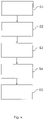
- 3 14 shows a schematic exemplary diagram D of a pump flow 142 over a period of time from a start time t 0 to an end time t 2 .
- the pump current 142 shown is, for example, during operation of a domestic dishwasher 1 of the 1 or 2 detected.
- a water diverter is switched over, for example, so that instead of the first hydraulic system 110 , the second hydraulic system 120 is now supplied with washing liquor. This means that in the time period t 0 -t 1 the first hydraulic arrangement 110 and in the time period t 1 -t 2 the second hydraulic arrangement 120 is acted upon with washing liquor.
- the pump current 142 is plotted on the ordinate axis of diagram D.
- three values I 0 , I 1 and I 2 are marked.
- I 0 corresponds, for example, to the pump current 142 that is required when the first hydraulic system 110 is subjected to washing liquor.
- This pump current 142 can also be referred to as the first pump current I 0 .
- I 1 corresponds, for example, to the pump current 142 that is required when the second hydraulic system 120 is acted upon when the third switching device 132 is in the first switching state, ie is disconnected from the second hydraulic system 120 .
- I 2 corresponds, for example, to the pump current 142 that is required when the second hydraulic arrangement 120 is acted upon when the third switching device 132 is in the second switching state, that is to say with the second hydraulic arrangement 120 is connected.
- I 1 and I 2 can also be referred to as the second pump current.
- Diagram D shows how pump flow 142 changes at switchover time t 1 when there is a switchover from first hydraulic system 110 to second hydraulic system 120 .
- the two possibilities with regard to the current switching state of the third spraying device 132 are shown, with the solid line representing the pump current 142 in the first switching state and the dashed line representing the pump current 142 in the second switching state. It can be seen that the pump current 142 is different in the two switching states.
- the difference ⁇ I 01 , ⁇ I 02 is shown for each switching state. The difference ⁇ I 01 , ⁇ I 02 that occurs is the greater, the higher the pump speed of pump device 140 is. In this respect, it can be advantageous to use an increased pump speed when determining the current switching state of the third spray device 132 .
- the control device 150 (see 1 ) is set up in particular to determine this difference ⁇ I 01 , ⁇ I 02 and to determine the current switching state of the third spraying device 132 as a function of the magnitude or the amount of the difference ⁇ I 01 , ⁇ I 02 . For this purpose, for example, the control device 150 compares the determined difference ⁇ I 01 , ⁇ I 02 with a predetermined threshold value.
- the second hydraulic arrangement 120 is assigned a fourth spraying device which, like the third spraying device 132, has two switching states.
- the control device 150 is then set up, for example, depending on the difference in the pump flow 142 between applying washing liquor to the first hydraulic system 110 and applying it the second hydraulic system 120 to determine with washing liquor whether the third spraying device 132 or the fourth spraying device is in the second switching state or whether the third spraying device 132 and the fourth spraying device are in the second switching state.
- a current switching state of a third spraying device 132 can be determined as a function of a difference ⁇ I 01 , ⁇ I 02 of a pump current 142 between applying washing liquor to the first hydraulic arrangement 110 and washing liquor to applying washing liquor to the second hydraulic arrangement 120 by a control device 150.
- the method includes, for example, the following method steps S1-S5.
- a first method step S1 the hydraulic system 110 is loaded with washing liquor.
- a pump device 140 is operated at a predetermined speed.
- the control device 150 detects the pump current 142 that is required to operate the pump device 140 when the first hydraulic arrangement 110 is acted upon.
- the control device 150 detects a first pump current I 0 . It can be provided in particular that the control device 150 records the pump current 142 over a predetermined time interval and records a time average of the pump current 142 in this time interval.
- control device 150 monitors the rotation of the pump device 140 during the detection of the pump current 142 .
- the second hydraulic arrangement 120 is loaded with washing liquor.
- the pump device 140 is operated in particular with the same pump speed as in the method steps S1 and S2.
- a fourth method step S4 which takes place in particular while the third method step S3 is being carried out, the control device 150 detects the pump current 142 that is required to operate the pump device 140 when the second hydraulic arrangement 120 is acted upon. In particular, the control device 150 detects a second pump current I 1 , I 2 .
- the second method step S2 Exemplary embodiments apply correspondingly to the fourth method step S4.
- a fifth method step S5 the control device 150 determines the current switching state of the third spraying device 132 as a function of the difference ⁇ I 01 , ⁇ I 02 in the pump current 142, in particular the first pump current I 0 and the second pump current I 1 , I 2 150 calculates a difference between the first pump current I 0 and the second pump current I 1 , I 2 and compares the result with a predefined threshold value. Depending on whether the difference is greater than the threshold value or less than the threshold value, control device 150 can determine the current switching state.
Landscapes
- Engineering & Computer Science (AREA)
- Water Supply & Treatment (AREA)
- Washing And Drying Of Tableware (AREA)
Applications Claiming Priority (2)
| Application Number | Priority Date | Filing Date | Title |
|---|---|---|---|
| DE102017216947.8A DE102017216947A1 (de) | 2017-09-25 | 2017-09-25 | Geschirrspülmaschine und Verfahren zum Betreiben einer Geschirrspülmaschine |
| PCT/EP2018/074421 WO2019057545A1 (de) | 2017-09-25 | 2018-09-11 | Geschirrspülmaschine und verfahren zum betreiben einer geschirrspülmaschine |
Publications (2)
| Publication Number | Publication Date |
|---|---|
| EP3687362A1 EP3687362A1 (de) | 2020-08-05 |
| EP3687362B1 true EP3687362B1 (de) | 2022-08-17 |
Family
ID=63637878
Family Applications (1)
| Application Number | Title | Priority Date | Filing Date |
|---|---|---|---|
| EP18772772.2A Active EP3687362B1 (de) | 2017-09-25 | 2018-09-11 | Geschirrspülmaschine und verfahren zum betreiben einer geschirrspülmaschine |
Country Status (6)
| Country | Link |
|---|---|
| US (1) | US11497373B2 (pl) |
| EP (1) | EP3687362B1 (pl) |
| CN (1) | CN111163672B (pl) |
| DE (1) | DE102017216947A1 (pl) |
| PL (1) | PL3687362T3 (pl) |
| WO (1) | WO2019057545A1 (pl) |
Families Citing this family (2)
| Publication number | Priority date | Publication date | Assignee | Title |
|---|---|---|---|---|
| DE102020208139A1 (de) * | 2020-06-30 | 2021-12-30 | BSH Hausgeräte GmbH | Geschirrspülmaschine, Verfahren zum Betreiben einer Geschirrspülmaschine und Computerprogrammprodukt |
| CN116269125A (zh) * | 2022-12-30 | 2023-06-23 | 艾欧史密斯(中国)热水器有限公司 | 清洗机喷淋装置的检测方法、控制装置、清洗机 |
Family Cites Families (18)
| Publication number | Priority date | Publication date | Assignee | Title |
|---|---|---|---|---|
| DE19630357A1 (de) * | 1996-07-26 | 1998-02-05 | Aweco Kunststofftech Geraete | Vorrichtung zur Regelung der Wassermenge in vorzugsweise Spülmaschinen |
| US7475696B2 (en) * | 2003-06-17 | 2009-01-13 | Whirlpool Corporation | Dishwasher having valved third-level sprayer |
| CN1567109A (zh) * | 2003-06-30 | 2005-01-19 | 乐金电子(天津)电器有限公司 | 洗碗机及其控制方法 |
| US20060219262A1 (en) * | 2005-04-04 | 2006-10-05 | Peterson Gregory A | Water fill level control for dishwasher and associated method |
| DE102007017274A1 (de) | 2007-04-12 | 2008-10-30 | BSH Bosch und Siemens Hausgeräte GmbH | Verfahren zur Lageerkennung eines Verschlusselements in einer Wasserweiche |
| DE102007041313A1 (de) * | 2007-08-31 | 2009-03-05 | BSH Bosch und Siemens Hausgeräte GmbH | Verfahren zum Betreiben einer Geschirrspülmaschine |
| CN102655801A (zh) * | 2009-12-25 | 2012-09-05 | 阿塞里克股份有限公司 | 包括微过滤器的洗碗机 |
| DE102011003688A1 (de) * | 2011-02-07 | 2012-08-09 | BSH Bosch und Siemens Hausgeräte GmbH | Geschirrspülmaschine und Verfahren zur Fehlerdetektion in einer Geschirrspülmaschine |
| DE102012101537A1 (de) * | 2012-02-27 | 2013-08-29 | Miele & Cie. Kg | Haushaltsgerät mit einer Kommunikationseinrichtung |
| US10244919B2 (en) * | 2012-11-08 | 2019-04-02 | Electrolux Home Products Corporation N.V. | Detecting operational state of a dishwasher |
| EP3082552B1 (en) * | 2013-12-20 | 2021-11-03 | Electrolux Appliances Aktiebolag | Arrangement in a dishwasher for creating a wash zone with intensified washing |
| EP3082556B1 (en) | 2013-12-20 | 2019-09-18 | Electrolux Appliances Aktiebolag | Dishwasher |
| US9596976B2 (en) | 2014-03-04 | 2017-03-21 | Haier Us Appliance Solutions, Inc. | Dishwasher appliance |
| KR101667589B1 (ko) * | 2014-06-12 | 2016-10-28 | 엘지전자 주식회사 | 식기세척기 및 식기세척기의 제어방법 |
| CN205094354U (zh) * | 2015-10-20 | 2016-03-23 | 佛山市顺德区美的洗涤电器制造有限公司 | 洗碗机 |
| US20170105595A1 (en) * | 2015-10-20 | 2017-04-20 | Electrolux Home Products, Inc. | User interface for a dishwasher |
| BR112018007322A2 (pt) | 2015-11-10 | 2018-10-23 | Electrolux Appliances AB | método para determinar se uma água de processo está presente em uma bomba de circulação, aparelho, programa de computador e produto |
| WO2017140335A1 (en) * | 2016-02-15 | 2017-08-24 | Electrolux Appliances Aktiebolag | Process water flow detection in circulation pump |
-
2017
- 2017-09-25 DE DE102017216947.8A patent/DE102017216947A1/de not_active Withdrawn
-
2018
- 2018-09-11 WO PCT/EP2018/074421 patent/WO2019057545A1/de not_active Ceased
- 2018-09-11 PL PL18772772.2T patent/PL3687362T3/pl unknown
- 2018-09-11 US US16/636,651 patent/US11497373B2/en active Active
- 2018-09-11 CN CN201880062396.9A patent/CN111163672B/zh active Active
- 2018-09-11 EP EP18772772.2A patent/EP3687362B1/de active Active
Also Published As
| Publication number | Publication date |
|---|---|
| US20210145242A1 (en) | 2021-05-20 |
| EP3687362A1 (de) | 2020-08-05 |
| US11497373B2 (en) | 2022-11-15 |
| CN111163672B (zh) | 2023-03-21 |
| PL3687362T3 (pl) | 2022-11-21 |
| DE102017216947A1 (de) | 2019-03-28 |
| WO2019057545A1 (de) | 2019-03-28 |
| CN111163672A (zh) | 2020-05-15 |
Similar Documents
| Publication | Publication Date | Title |
|---|---|---|
| DE102007042076A1 (de) | Geschirrspülmaschine mit regelbarer Umwälzpumpe sowie Verfahren zum Spülen von Geschirr | |
| DE102008024543A1 (de) | Verfahren zum Betreiben einer Spülmaschine sowie Spülmaschine | |
| EP3687362B1 (de) | Geschirrspülmaschine und verfahren zum betreiben einer geschirrspülmaschine | |
| EP2183423B1 (de) | Verfahren zum steuern eines waschprozesses | |
| EP4179946A1 (de) | Verfahren zum betreiben eines wasserführenden haushaltsgeräts | |
| DE102011004949B4 (de) | Geschirrspülmaschine und Verfahren zum Betrieb derselben | |
| DE10220839A1 (de) | Geschirrspülmaschine und Verfahren zum Spülen von Spülgut in derselben | |
| EP2496126B1 (de) | Geschirrspülmaschine mit einer optimierten füllsequenz | |
| WO2021239534A1 (de) | System mit einer geschirrspülmaschine, verfahren und computerprogrammprodukt | |
| EP3624664B1 (de) | Geschirrspülmaschine und verfahren zum betreiben einer geschirrspülmaschine | |
| WO2020043799A1 (de) | Geschirrspülmaschine, verfahren zum betreiben einer geschirrspülmaschine und computerprogrammprodukt | |
| EP4171344B1 (de) | Geschirrspülmaschine, verfahren zum betreiben einer geschirrspülmaschine und computerprogrammprodukt | |
| DE10230567A1 (de) | Geschirrspülmaschine und Verfahren zum Spülen von Spülgut in derselben | |
| EP2319384B1 (de) | System zur Reinigung von Geschirr | |
| EP4072391B1 (de) | Haushalts-geschirrspülmaschine und verfahren | |
| WO2020043800A1 (de) | Haushalts-geschirrspülmaschine, verfahren zum betreiben einer haushalts-geschirrspülmaschine und computerprogrammprodukt | |
| DE102021203799A1 (de) | Geschirrspülmaschine und Verfahren zur Reinigung von Reinigungsgut | |
| DE102016120922A1 (de) | Geschirrspülmaschine | |
| DE102005030720A1 (de) | Transportgeschirrspülmaschine und Betriebsverfahren hierfür | |
| EP1345525A1 (de) | Verfahren zum betrieb einer geschirrspülmaschine und geschirrspülmaschine | |
| DE102017207214B4 (de) | Wasserführendes Haushaltsgerät und Verfahren zum Betreiben eines wasserführenden Haushaltsgeräts | |
| DE102005061808A1 (de) | Geschirrspülmaschine und Verfahren zum Betreiben einer Geschirrspülmaschine für Niedertemperatur-Klarspülmittel | |
| DE102015122782A1 (de) | Verbesserte Waschvorrichtung für eine Tunnelgeschirrspülmaschine und zugeordnete Geschirrspülmaschine | |
| EP1216646A1 (de) | Verfahren zum Betrieb einer Geschirrspülmaschine und Geschirrspülmaschine |
Legal Events
| Date | Code | Title | Description |
|---|---|---|---|
| STAA | Information on the status of an ep patent application or granted ep patent |
Free format text: STATUS: UNKNOWN |
|
| STAA | Information on the status of an ep patent application or granted ep patent |
Free format text: STATUS: THE INTERNATIONAL PUBLICATION HAS BEEN MADE |
|
| PUAI | Public reference made under article 153(3) epc to a published international application that has entered the european phase |
Free format text: ORIGINAL CODE: 0009012 |
|
| STAA | Information on the status of an ep patent application or granted ep patent |
Free format text: STATUS: REQUEST FOR EXAMINATION WAS MADE |
|
| 17P | Request for examination filed |
Effective date: 20200428 |
|
| AK | Designated contracting states |
Kind code of ref document: A1 Designated state(s): AL AT BE BG CH CY CZ DE DK EE ES FI FR GB GR HR HU IE IS IT LI LT LU LV MC MK MT NL NO PL PT RO RS SE SI SK SM TR |
|
| AX | Request for extension of the european patent |
Extension state: BA ME |
|
| DAV | Request for validation of the european patent (deleted) | ||
| DAX | Request for extension of the european patent (deleted) | ||
| GRAP | Despatch of communication of intention to grant a patent |
Free format text: ORIGINAL CODE: EPIDOSNIGR1 |
|
| STAA | Information on the status of an ep patent application or granted ep patent |
Free format text: STATUS: GRANT OF PATENT IS INTENDED |
|
| INTG | Intention to grant announced |
Effective date: 20220408 |
|
| GRAS | Grant fee paid |
Free format text: ORIGINAL CODE: EPIDOSNIGR3 |
|
| GRAA | (expected) grant |
Free format text: ORIGINAL CODE: 0009210 |
|
| STAA | Information on the status of an ep patent application or granted ep patent |
Free format text: STATUS: THE PATENT HAS BEEN GRANTED |
|
| AK | Designated contracting states |
Kind code of ref document: B1 Designated state(s): AL AT BE BG CH CY CZ DE DK EE ES FI FR GB GR HR HU IE IS IT LI LT LU LV MC MK MT NL NO PL PT RO RS SE SI SK SM TR |
|
| REG | Reference to a national code |
Ref country code: CH Ref legal event code: EP |
|
| REG | Reference to a national code |
Ref country code: DE Ref legal event code: R096 Ref document number: 502018010433 Country of ref document: DE |
|
| REG | Reference to a national code |
Ref country code: IE Ref legal event code: FG4D Free format text: LANGUAGE OF EP DOCUMENT: GERMAN |
|
| REG | Reference to a national code |
Ref country code: AT Ref legal event code: REF Ref document number: 1511610 Country of ref document: AT Kind code of ref document: T Effective date: 20220915 |
|
| REG | Reference to a national code |
Ref country code: NL Ref legal event code: MP Effective date: 20220817 |
|
| REG | Reference to a national code |
Ref country code: LT Ref legal event code: MG9D |
|
| PG25 | Lapsed in a contracting state [announced via postgrant information from national office to epo] |
Ref country code: SE Free format text: LAPSE BECAUSE OF FAILURE TO SUBMIT A TRANSLATION OF THE DESCRIPTION OR TO PAY THE FEE WITHIN THE PRESCRIBED TIME-LIMIT Effective date: 20220817 Ref country code: RS Free format text: LAPSE BECAUSE OF FAILURE TO SUBMIT A TRANSLATION OF THE DESCRIPTION OR TO PAY THE FEE WITHIN THE PRESCRIBED TIME-LIMIT Effective date: 20220817 Ref country code: PT Free format text: LAPSE BECAUSE OF FAILURE TO SUBMIT A TRANSLATION OF THE DESCRIPTION OR TO PAY THE FEE WITHIN THE PRESCRIBED TIME-LIMIT Effective date: 20221219 Ref country code: NO Free format text: LAPSE BECAUSE OF FAILURE TO SUBMIT A TRANSLATION OF THE DESCRIPTION OR TO PAY THE FEE WITHIN THE PRESCRIBED TIME-LIMIT Effective date: 20221117 Ref country code: NL Free format text: LAPSE BECAUSE OF FAILURE TO SUBMIT A TRANSLATION OF THE DESCRIPTION OR TO PAY THE FEE WITHIN THE PRESCRIBED TIME-LIMIT Effective date: 20220817 Ref country code: LV Free format text: LAPSE BECAUSE OF FAILURE TO SUBMIT A TRANSLATION OF THE DESCRIPTION OR TO PAY THE FEE WITHIN THE PRESCRIBED TIME-LIMIT Effective date: 20220817 Ref country code: LT Free format text: LAPSE BECAUSE OF FAILURE TO SUBMIT A TRANSLATION OF THE DESCRIPTION OR TO PAY THE FEE WITHIN THE PRESCRIBED TIME-LIMIT Effective date: 20220817 Ref country code: FI Free format text: LAPSE BECAUSE OF FAILURE TO SUBMIT A TRANSLATION OF THE DESCRIPTION OR TO PAY THE FEE WITHIN THE PRESCRIBED TIME-LIMIT Effective date: 20220817 |
|
| PG25 | Lapsed in a contracting state [announced via postgrant information from national office to epo] |
Ref country code: IS Free format text: LAPSE BECAUSE OF FAILURE TO SUBMIT A TRANSLATION OF THE DESCRIPTION OR TO PAY THE FEE WITHIN THE PRESCRIBED TIME-LIMIT Effective date: 20221217 Ref country code: HR Free format text: LAPSE BECAUSE OF FAILURE TO SUBMIT A TRANSLATION OF THE DESCRIPTION OR TO PAY THE FEE WITHIN THE PRESCRIBED TIME-LIMIT Effective date: 20220817 Ref country code: GR Free format text: LAPSE BECAUSE OF FAILURE TO SUBMIT A TRANSLATION OF THE DESCRIPTION OR TO PAY THE FEE WITHIN THE PRESCRIBED TIME-LIMIT Effective date: 20221118 |
|
| PG25 | Lapsed in a contracting state [announced via postgrant information from national office to epo] |
Ref country code: SM Free format text: LAPSE BECAUSE OF FAILURE TO SUBMIT A TRANSLATION OF THE DESCRIPTION OR TO PAY THE FEE WITHIN THE PRESCRIBED TIME-LIMIT Effective date: 20220817 Ref country code: RO Free format text: LAPSE BECAUSE OF FAILURE TO SUBMIT A TRANSLATION OF THE DESCRIPTION OR TO PAY THE FEE WITHIN THE PRESCRIBED TIME-LIMIT Effective date: 20220817 Ref country code: ES Free format text: LAPSE BECAUSE OF FAILURE TO SUBMIT A TRANSLATION OF THE DESCRIPTION OR TO PAY THE FEE WITHIN THE PRESCRIBED TIME-LIMIT Effective date: 20220817 Ref country code: DK Free format text: LAPSE BECAUSE OF FAILURE TO SUBMIT A TRANSLATION OF THE DESCRIPTION OR TO PAY THE FEE WITHIN THE PRESCRIBED TIME-LIMIT Effective date: 20220817 |
|
| REG | Reference to a national code |
Ref country code: CH Ref legal event code: PL |
|
| REG | Reference to a national code |
Ref country code: DE Ref legal event code: R097 Ref document number: 502018010433 Country of ref document: DE |
|
| REG | Reference to a national code |
Ref country code: BE Ref legal event code: MM Effective date: 20220930 |
|
| PG25 | Lapsed in a contracting state [announced via postgrant information from national office to epo] |
Ref country code: SK Free format text: LAPSE BECAUSE OF FAILURE TO SUBMIT A TRANSLATION OF THE DESCRIPTION OR TO PAY THE FEE WITHIN THE PRESCRIBED TIME-LIMIT Effective date: 20220817 Ref country code: MC Free format text: LAPSE BECAUSE OF FAILURE TO SUBMIT A TRANSLATION OF THE DESCRIPTION OR TO PAY THE FEE WITHIN THE PRESCRIBED TIME-LIMIT Effective date: 20220817 Ref country code: EE Free format text: LAPSE BECAUSE OF FAILURE TO SUBMIT A TRANSLATION OF THE DESCRIPTION OR TO PAY THE FEE WITHIN THE PRESCRIBED TIME-LIMIT Effective date: 20220817 |
|
| PLBE | No opposition filed within time limit |
Free format text: ORIGINAL CODE: 0009261 |
|
| STAA | Information on the status of an ep patent application or granted ep patent |
Free format text: STATUS: NO OPPOSITION FILED WITHIN TIME LIMIT |
|
| PG25 | Lapsed in a contracting state [announced via postgrant information from national office to epo] |
Ref country code: LU Free format text: LAPSE BECAUSE OF NON-PAYMENT OF DUE FEES Effective date: 20220911 Ref country code: AL Free format text: LAPSE BECAUSE OF FAILURE TO SUBMIT A TRANSLATION OF THE DESCRIPTION OR TO PAY THE FEE WITHIN THE PRESCRIBED TIME-LIMIT Effective date: 20220817 |
|
| 26N | No opposition filed |
Effective date: 20230519 |
|
| GBPC | Gb: european patent ceased through non-payment of renewal fee |
Effective date: 20221117 |
|
| PG25 | Lapsed in a contracting state [announced via postgrant information from national office to epo] |
Ref country code: LI Free format text: LAPSE BECAUSE OF NON-PAYMENT OF DUE FEES Effective date: 20220930 Ref country code: IE Free format text: LAPSE BECAUSE OF NON-PAYMENT OF DUE FEES Effective date: 20220911 Ref country code: FR Free format text: LAPSE BECAUSE OF NON-PAYMENT OF DUE FEES Effective date: 20221017 Ref country code: CH Free format text: LAPSE BECAUSE OF NON-PAYMENT OF DUE FEES Effective date: 20220930 |
|
| PG25 | Lapsed in a contracting state [announced via postgrant information from national office to epo] |
Ref country code: SI Free format text: LAPSE BECAUSE OF FAILURE TO SUBMIT A TRANSLATION OF THE DESCRIPTION OR TO PAY THE FEE WITHIN THE PRESCRIBED TIME-LIMIT Effective date: 20220817 |
|
| PG25 | Lapsed in a contracting state [announced via postgrant information from national office to epo] |
Ref country code: BE Free format text: LAPSE BECAUSE OF NON-PAYMENT OF DUE FEES Effective date: 20220930 |
|
| PG25 | Lapsed in a contracting state [announced via postgrant information from national office to epo] |
Ref country code: GB Free format text: LAPSE BECAUSE OF NON-PAYMENT OF DUE FEES Effective date: 20221117 |
|
| PG25 | Lapsed in a contracting state [announced via postgrant information from national office to epo] |
Ref country code: CY Free format text: LAPSE BECAUSE OF FAILURE TO SUBMIT A TRANSLATION OF THE DESCRIPTION OR TO PAY THE FEE WITHIN THE PRESCRIBED TIME-LIMIT Effective date: 20220817 |
|
| PG25 | Lapsed in a contracting state [announced via postgrant information from national office to epo] |
Ref country code: MK Free format text: LAPSE BECAUSE OF FAILURE TO SUBMIT A TRANSLATION OF THE DESCRIPTION OR TO PAY THE FEE WITHIN THE PRESCRIBED TIME-LIMIT Effective date: 20220817 Ref country code: IT Free format text: LAPSE BECAUSE OF FAILURE TO SUBMIT A TRANSLATION OF THE DESCRIPTION OR TO PAY THE FEE WITHIN THE PRESCRIBED TIME-LIMIT Effective date: 20220817 Ref country code: HU Free format text: LAPSE BECAUSE OF FAILURE TO SUBMIT A TRANSLATION OF THE DESCRIPTION OR TO PAY THE FEE WITHIN THE PRESCRIBED TIME-LIMIT; INVALID AB INITIO Effective date: 20180911 |
|
| PG25 | Lapsed in a contracting state [announced via postgrant information from national office to epo] |
Ref country code: BG Free format text: LAPSE BECAUSE OF FAILURE TO SUBMIT A TRANSLATION OF THE DESCRIPTION OR TO PAY THE FEE WITHIN THE PRESCRIBED TIME-LIMIT Effective date: 20220817 |
|
| PG25 | Lapsed in a contracting state [announced via postgrant information from national office to epo] |
Ref country code: MT Free format text: LAPSE BECAUSE OF FAILURE TO SUBMIT A TRANSLATION OF THE DESCRIPTION OR TO PAY THE FEE WITHIN THE PRESCRIBED TIME-LIMIT Effective date: 20220817 |
|
| REG | Reference to a national code |
Ref country code: AT Ref legal event code: MM01 Ref document number: 1511610 Country of ref document: AT Kind code of ref document: T Effective date: 20230911 |
|
| PG25 | Lapsed in a contracting state [announced via postgrant information from national office to epo] |
Ref country code: AT Free format text: LAPSE BECAUSE OF NON-PAYMENT OF DUE FEES Effective date: 20230911 |
|
| PG25 | Lapsed in a contracting state [announced via postgrant information from national office to epo] |
Ref country code: AT Free format text: LAPSE BECAUSE OF NON-PAYMENT OF DUE FEES Effective date: 20230911 |
|
| PGFP | Annual fee paid to national office [announced via postgrant information from national office to epo] |
Ref country code: DE Payment date: 20250930 Year of fee payment: 8 |
|
| PGFP | Annual fee paid to national office [announced via postgrant information from national office to epo] |
Ref country code: TR Payment date: 20250908 Year of fee payment: 8 Ref country code: PL Payment date: 20250829 Year of fee payment: 8 |
|
| PGFP | Annual fee paid to national office [announced via postgrant information from national office to epo] |
Ref country code: CZ Payment date: 20250902 Year of fee payment: 8 |