EP3686048B1 - Zugentlastung für einen kabelschlauch - Google Patents
Zugentlastung für einen kabelschlauch Download PDFInfo
- Publication number
- EP3686048B1 EP3686048B1 EP20000007.3A EP20000007A EP3686048B1 EP 3686048 B1 EP3686048 B1 EP 3686048B1 EP 20000007 A EP20000007 A EP 20000007A EP 3686048 B1 EP3686048 B1 EP 3686048B1
- Authority
- EP
- European Patent Office
- Prior art keywords
- cable conduit
- cable
- lines
- receptacle element
- conductor receptacle
- Prior art date
- Legal status (The legal status is an assumption and is not a legal conclusion. Google has not performed a legal analysis and makes no representation as to the accuracy of the status listed.)
- Active
Links
Images

Classifications
-
- B—PERFORMING OPERATIONS; TRANSPORTING
- B60—VEHICLES IN GENERAL
- B60L—PROPULSION OF ELECTRICALLY-PROPELLED VEHICLES; SUPPLYING ELECTRIC POWER FOR AUXILIARY EQUIPMENT OF ELECTRICALLY-PROPELLED VEHICLES; ELECTRODYNAMIC BRAKE SYSTEMS FOR VEHICLES IN GENERAL; MAGNETIC SUSPENSION OR LEVITATION FOR VEHICLES; MONITORING OPERATING VARIABLES OF ELECTRICALLY-PROPELLED VEHICLES; ELECTRIC SAFETY DEVICES FOR ELECTRICALLY-PROPELLED VEHICLES
- B60L53/00—Methods of charging batteries, specially adapted for electric vehicles; Charging stations or on-board charging equipment therefor; Exchange of energy storage elements in electric vehicles
- B60L53/10—Methods of charging batteries, specially adapted for electric vehicles; Charging stations or on-board charging equipment therefor; Exchange of energy storage elements in electric vehicles characterised by the energy transfer between the charging station and the vehicle
- B60L53/14—Conductive energy transfer
- B60L53/18—Cables specially adapted for charging electric vehicles
-
- B—PERFORMING OPERATIONS; TRANSPORTING
- B60—VEHICLES IN GENERAL
- B60L—PROPULSION OF ELECTRICALLY-PROPELLED VEHICLES; SUPPLYING ELECTRIC POWER FOR AUXILIARY EQUIPMENT OF ELECTRICALLY-PROPELLED VEHICLES; ELECTRODYNAMIC BRAKE SYSTEMS FOR VEHICLES IN GENERAL; MAGNETIC SUSPENSION OR LEVITATION FOR VEHICLES; MONITORING OPERATING VARIABLES OF ELECTRICALLY-PROPELLED VEHICLES; ELECTRIC SAFETY DEVICES FOR ELECTRICALLY-PROPELLED VEHICLES
- B60L53/00—Methods of charging batteries, specially adapted for electric vehicles; Charging stations or on-board charging equipment therefor; Exchange of energy storage elements in electric vehicles
- B60L53/10—Methods of charging batteries, specially adapted for electric vehicles; Charging stations or on-board charging equipment therefor; Exchange of energy storage elements in electric vehicles characterised by the energy transfer between the charging station and the vehicle
- B60L53/14—Conductive energy transfer
- B60L53/16—Connectors, e.g. plugs or sockets, specially adapted for charging electric vehicles
-
- B—PERFORMING OPERATIONS; TRANSPORTING
- B60—VEHICLES IN GENERAL
- B60L—PROPULSION OF ELECTRICALLY-PROPELLED VEHICLES; SUPPLYING ELECTRIC POWER FOR AUXILIARY EQUIPMENT OF ELECTRICALLY-PROPELLED VEHICLES; ELECTRODYNAMIC BRAKE SYSTEMS FOR VEHICLES IN GENERAL; MAGNETIC SUSPENSION OR LEVITATION FOR VEHICLES; MONITORING OPERATING VARIABLES OF ELECTRICALLY-PROPELLED VEHICLES; ELECTRIC SAFETY DEVICES FOR ELECTRICALLY-PROPELLED VEHICLES
- B60L53/00—Methods of charging batteries, specially adapted for electric vehicles; Charging stations or on-board charging equipment therefor; Exchange of energy storage elements in electric vehicles
- B60L53/30—Constructional details of charging stations
- B60L53/302—Cooling of charging equipment
-
- H—ELECTRICITY
- H01—ELECTRIC ELEMENTS
- H01R—ELECTRICALLY-CONDUCTIVE CONNECTIONS; STRUCTURAL ASSOCIATIONS OF A PLURALITY OF MUTUALLY-INSULATED ELECTRICAL CONNECTING ELEMENTS; COUPLING DEVICES; CURRENT COLLECTORS
- H01R13/00—Details of coupling devices of the kinds covered by groups H01R12/70 or H01R24/00 - H01R33/00
- H01R13/58—Means for relieving strain on wire connection, e.g. cord grip, for avoiding loosening of connections between wires and terminals within a coupling device terminating a cable
- H01R13/582—Means for relieving strain on wire connection, e.g. cord grip, for avoiding loosening of connections between wires and terminals within a coupling device terminating a cable the cable being clamped between assembled parts of the housing
- H01R13/5825—Means for relieving strain on wire connection, e.g. cord grip, for avoiding loosening of connections between wires and terminals within a coupling device terminating a cable the cable being clamped between assembled parts of the housing the means comprising additional parts captured between housing parts and cable
-
- H—ELECTRICITY
- H01—ELECTRIC ELEMENTS
- H01R—ELECTRICALLY-CONDUCTIVE CONNECTIONS; STRUCTURAL ASSOCIATIONS OF A PLURALITY OF MUTUALLY-INSULATED ELECTRICAL CONNECTING ELEMENTS; COUPLING DEVICES; CURRENT COLLECTORS
- H01R13/00—Details of coupling devices of the kinds covered by groups H01R12/70 or H01R24/00 - H01R33/00
- H01R13/46—Bases; Cases
- H01R13/52—Dustproof, splashproof, drip-proof, waterproof, or flameproof cases
- H01R13/5202—Sealing means between parts of housing or between housing part and a wall, e.g. sealing rings
-
- Y—GENERAL TAGGING OF NEW TECHNOLOGICAL DEVELOPMENTS; GENERAL TAGGING OF CROSS-SECTIONAL TECHNOLOGIES SPANNING OVER SEVERAL SECTIONS OF THE IPC; TECHNICAL SUBJECTS COVERED BY FORMER USPC CROSS-REFERENCE ART COLLECTIONS [XRACs] AND DIGESTS
- Y02—TECHNOLOGIES OR APPLICATIONS FOR MITIGATION OR ADAPTATION AGAINST CLIMATE CHANGE
- Y02T—CLIMATE CHANGE MITIGATION TECHNOLOGIES RELATED TO TRANSPORTATION
- Y02T10/00—Road transport of goods or passengers
- Y02T10/60—Other road transportation technologies with climate change mitigation effect
- Y02T10/70—Energy storage systems for electromobility, e.g. batteries
-
- Y—GENERAL TAGGING OF NEW TECHNOLOGICAL DEVELOPMENTS; GENERAL TAGGING OF CROSS-SECTIONAL TECHNOLOGIES SPANNING OVER SEVERAL SECTIONS OF THE IPC; TECHNICAL SUBJECTS COVERED BY FORMER USPC CROSS-REFERENCE ART COLLECTIONS [XRACs] AND DIGESTS
- Y02—TECHNOLOGIES OR APPLICATIONS FOR MITIGATION OR ADAPTATION AGAINST CLIMATE CHANGE
- Y02T—CLIMATE CHANGE MITIGATION TECHNOLOGIES RELATED TO TRANSPORTATION
- Y02T10/00—Road transport of goods or passengers
- Y02T10/60—Other road transportation technologies with climate change mitigation effect
- Y02T10/7072—Electromobility specific charging systems or methods for batteries, ultracapacitors, supercapacitors or double-layer capacitors
-
- Y—GENERAL TAGGING OF NEW TECHNOLOGICAL DEVELOPMENTS; GENERAL TAGGING OF CROSS-SECTIONAL TECHNOLOGIES SPANNING OVER SEVERAL SECTIONS OF THE IPC; TECHNICAL SUBJECTS COVERED BY FORMER USPC CROSS-REFERENCE ART COLLECTIONS [XRACs] AND DIGESTS
- Y02—TECHNOLOGIES OR APPLICATIONS FOR MITIGATION OR ADAPTATION AGAINST CLIMATE CHANGE
- Y02T—CLIMATE CHANGE MITIGATION TECHNOLOGIES RELATED TO TRANSPORTATION
- Y02T90/00—Enabling technologies or technologies with a potential or indirect contribution to GHG emissions mitigation
- Y02T90/10—Technologies relating to charging of electric vehicles
- Y02T90/14—Plug-in electric vehicles
Definitions
- the invention is based on a system consisting of a cable hose outlet and a cable hose according to the generic type of independent claim 1.
- the invention is also based on a car charging connector or a charging station according to the independent claim 7.
- Cable hoses are used in particular in car charging connectors that are specially designed for fast charging.
- the cables required for a charging process run in the cable hoses.
- the DE 10 2017 108 174 A1 shows a car charging connector for an electric vehicle.
- Such car charging connectors are provided with electrical lines with a large diameter in order to be able to transmit the currents required for the charging process.
- the connector shown is for high voltage electric and hybrid vehicle cables and includes a plug and receptacle into which the stranded wire of the high voltage cable is plugged.
- the plug-socket connection is completely overmoulded with a thermoplastic elastomer from the outside for sealing.
- the EP 3 103 173 A1 shows a charging system for an electric vehicle, comprising: a power supply; a cable having first and second ends, the first end being attached to the power supply, the cable including a charging conduit and a cooling conduit each extending from the first end to the second end extend; and a connector attached to the second end of the cable.
- the EP 3 362 312 A1 shows a cable for a car charger connector.
- a cable comprises a cable hose, which encloses a hose interior, at least one line wire extending in the hose interior for conducting an electric current, and a fluid line extending in the hose interior for conducting a fluid for cooling the cable.
- the U.S. 6,396,241 B1 shows a charging connector for inductive charging of an electric vehicle.
- the U.S. 9,257,857 B2 shows a cable gland with a special cable positioning device.
- car charging connectors can be supplied with coolant via suitable lines in order to quickly dissipate the heat generated during the charging process and thus speed up the charging process;
- the different lines are combined in a cable tube. Due to frequent bending of the cable tube during changing charging processes, individual lines in the cable tube can become twisted and have a negative impact on each other. In the worst case, cables can become detached from a contact element due to strong mechanical stress.
- the object of the invention is to propose a reliable car charging connector.
- the system according to the invention consists of a cable hose outlet and a cable hose attached to it.
- the cable hose outlet is molded onto a charging connector.
- the cable hose outlet is attached to a charging station.
- the cable hose outlet is preferably a separate part that is fastened in the housing of the charging station.
- Electrical lines and/or optical lines and/or coolant-carrying lines are located in the cable tube, which run, for example, from a charging station to a charging plug connector.
- a conductor receiving element is arranged inside the cable hose.
- the conductor receiving element has receptacles in which the lines are arranged at least in certain areas.
- the cable hose has a clamping ring on the outside.
- the clamping ring is arranged in the area of the conductor receiving element.
- a force is exerted in the radial direction on the jacket of the clamping ring Exercised cable hose, whereby the cable hose is pressed onto the conductor receiving element.
- At least part of the cable hose runs inside the cylindrical cable hose outlet. This is the so-called end section of the cable hose, which is connected either to the car charging connector or to the associated charging station.
- the part of the cable hose that is pushed into the cable hose outlet has the clamping ring.
- the clamping ring is arranged in a recess on the inside of the cable hose outlet. Tensile forces acting on the cable hose or the lines are absorbed by the clamping ring located in the recess.
- the conductor receiving element has an essentially cylindrical basic shape.
- receptacles for the lines run in the axial direction.
- the recordings are recesses with a part-circular cross section.
- the cross-sectional radius of the recesses is adapted to the diameter or to the cross-sectional radius of the associated line.
- the receptacles are advantageously arranged rotationally symmetrically in the conductor receptacle element. This prevents twisting of the conductors in the cable tube.
- outside diameter of the conductor receiving element is only slightly smaller than the inside diameter of the cable tube. This prevents what is known as unfolding of the cable hose when it is pressed by the clamping ring as described above.
- the cable hose outlet advantageously has a seal which is arranged at the end of the cable hose outlet.
- the seal protects the system from the ingress of media such as dust and water.
- the seal offers kink and bending protection for the cable hose, since this is particularly susceptible to mechanical stress at the end of the cable hose outlet.
- the seal has a peripheral web on the outside, which is arranged in an internal groove of the cable hose outlet. As a result, the seal is held captive on the cable hose outlet.
- figure 1 1 is a side view of a car charging connector 1, the housing of which is shown partially open.
- the car charging connector 1 has a cable hose outlet 2, via which the lines 3, 3', 3", 3′′′ connected to the car charging connector 1 are routed into the housing.
- the lines 3, 3', 3", 3′′′ are connected to the contact elements (not shown) of the car charger connector 1 is connected.
- the lines 3, 3′, 3′′, 3′′′ can be live or can supply the car charging connector 1 with cooling liquid.
- the lines 3, 3′, 3′′, 3′′′ run in a cable hose 4, which partially protrudes into the cable hose outlet 2.
- the lines 3, 3′, 3′′, 3′′′ are arranged in receptacles 6 of a conductor receiving element 5.
- the conductor holding element 5 is in turn arranged in the cable hose 4 .
- the receptacles 6 have a part-circular cross-section, the radius of which is adapted to the cross-section of the respective line 3, 3', 3", 3′′′.
- the outside diameter D L of the conductor receiving element 5 is only slightly smaller than the inside diameter D K of the cable tube 4.
- the outside diameter D L of the conductor receiving element 5 is adapted to the inside diameter D K of the cable tube 4.
- a clamping ring 7 is provided on the outside of the cable hose 4 in the area of the conductor receiving element 5 .
- the clamping ring 7 exercises a radial force on the outer sheath of the cable hose 4. As a result, the inside of the cable hose 4 is pressed onto the conductor receiving element 5 .
- a seal 8 is arranged at the end of the cable hose outlet 2 .
- the outer shape of the seal 8 tapers in the shape of a funnel in the cable outlet direction.
- the diameter of the passage opening of the seal 8 is adapted to the outer radius of the cable hose 4 .
- the seal 8 also offers so-called kink protection for the cable hose 4.
Landscapes
- Engineering & Computer Science (AREA)
- Power Engineering (AREA)
- Transportation (AREA)
- Mechanical Engineering (AREA)
- Electric Propulsion And Braking For Vehicles (AREA)
Description
- Die Erfindung geht aus von einem System bestehend aus einem Kabelschlauchabgang und einem Kabelschlauch nach der Gattung des unabhängigen Anspruchs 1. Weiterhin geht die Erfindung aus von einem Autoladesteckverbinder oder einer Ladesäule gemäß des nebengeordneten Anspruchs 7.
- Kabelschläuche werden insbesondere bei Autoladesteckverbinder, die speziell für einen schnellen Ladevorgang ausgestaltet sind. In den Kabelschläuchen verlaufen die für einen Ladevorgang notwendigen Leitungen.
- Die
DE 10 2017 108 174 A1 zeigt einen Autoladesteckverbinder für ein Elektrofahrzeug. Derartige Autoladesteckverbinder werden mit elektrischen Leitungen mit einem großen Durchmesser versehen, um die für den Ladevorgang notwendigen Ströme übertragen zu können. - Die in
EP 2 112 721 A1 gezeigte Steckerverbindung ist für Hochspannungskabel von Elektro- und Hybridfahrzeugen bestimmt, und schließt einen Stecker mit Aufnahmebuchse ein, in welche die Kabellitze des Hochspannungskabels eingesteckt wird. Die Stecker-Buchsenverbindung wird von außen zur Abdichtung komplett mit einem thermoplastischen Elastomer umspritzt. - Die
EP 3 103 173 A1 zeigt ein Ladesystem für ein elektrisches Fahrzeug, umfassend: Eine Stromversorgung; ein Kabel, das ein erstes und ein zweites Ende aufweist, wobei das erste Ende an der Stromversorgung angebracht ist, wobei das Kabel eine Ladeleitung und eine Kühlrohrleitung umfasst, die sich jeweils von dem ersten Ende zu dem zweiten Ende erstrecken; und einen Verbinder, der an dem zweiten Ende des Kabels angebracht ist. - Die
EP 3 362 312 A1 zeigt ein Kabel für einen Autoladesteckverbinder. Ein derartiges Kabel umfasst einen Kabelschlauch, der einen Schlauchinnenraum einfasst, zumindest eine in dem Schlauchinnenraum erstreckte Leitungsader zum Leiten eines elektrischen Stroms und eine in dem Schlauchinnenraum erstreckte Fluidleitung zum Führen eines Fluids zum Kühlen des Kabels. - Die
US 6 396 241 B1 zeigt einen Ladesteckverbinder zum induktiven Laden eines Elektrofahrzeugs. - Die
US 9 257 857 B2 - Aus der
DE 10 2016 112 306 A1 geht hervor, dass Autoladesteckverbinder über geeignete Leitungen mit Kühlflüssigkeit versorgt werden können, um die beim Ladevorgang entstehende Wärme schnell abzutransportieren und damit den Ladevorgang zu beschleunigen; - Die unterschiedlichen Leitungen werden in einem Kabelschlauch zusammengefasst. Durch ein häufiges Verbiegen des Kabelschlauchs bei wechselnden Ladevorgängen, können sich einzelne Leitungen im Kabelschlauch verdrehen und sich gegenseitig negativ beeinflussen. Im schlimmsten Fall können sich Leitungen, durch starke mechanische Beanspruchung, von einem Kontaktelement lösen.
- Die Aufgabe der Erfindung besteht darin, einen zuverlässigen Autoladesteckverbinder vorzuschlagen.
- Die Aufgabe wird durch die Merkmale des unabhängigen Anspruchs 1 gelöst. Weiterhin wird diese Aufgabe durch die Merkmale des nebengeordneten Anspruchs 7 gelöst.
- Vorteilhafte Ausgestaltungen der Erfindung sind in den Unteransprüchen angegeben.
- Das erfindungsgemäße System besteht aus einem Kabelschlauchabgang und einem daran angebrachten Kabelschlauch. Der Kabelschlauchabgang ist an einem Ladesteckverbinder angeformt. Alternativ ist der Kabelschlauchabgang an einer Ladesäule angebracht. In diesem Fall handelt es sich beim Kabelschlauchabgang vorzugsweise um ein separates Teil, welches im Gehäuse der Ladesäule befestigt ist.
- In dem Kabelschlauch befinden sich elektrische Leitungen und/oder optische Leitungen und/oder kühlflüssigkeitsführende Leitungen, die beispielsweise von einer Ladesäule zu einem Ladesteckverbinder verlaufen.
- Innerhalb des Kabelschlauches ist ein Leiteraufnahmeelement angeordnet. Das Leiteraufnahmeelement weist Aufnahmen auf, in denen die Leitungen zumindest bereichsweise angeordnet sind.
- Der Kabelschlauch weist außenseitig einen Klemmring auf. Der Klemmring ist im Bereich des Leiteraufnahmeelements angeordnet. Über den Klemmring wird eine Kraft in radialer Richtung auf den Mantel des Kabelschlauches ausgeübt, wodurch der Kabelschlauch auf das Leiteraufnahmeelement gepresst ist.
- Zumindest ein Teil des Kabelschlauches verläuft innerhalb des zylinderförmigen Kabelschlauchabgangs. Es handelt sich dabei um den sogenannten Endabschnitt des Kabelschlauches, der entweder an den Autoladesteckverbinder oder an der zugehörigen Ladestation angeschlossen wird. Der in den Kabelschlauchabgang eingeschobene Teil des Kabelschlauches weist den Klemmring auf. Der Klemmring ist in einer innenseitigen Ausnehmung des Kabelschlauchabgangs angeordnet. Über den in der Ausnehmung befindlichen Klemmring werden an den Kabelschlauch bzw. an den Leitungen angreifende Zugkräfte abgefangen.
- Das Leiteraufnahmeelement weist eine im Wesentlichen zylinderförmige Grundform auf. In der Mantelfläche des Leiteraufnahmeelements verlaufen in axialer Richtung Aufnahmen für die Leitungen. Bei den Aufnahmen handelt es sich um Aussparungen mit einem teilkreisförmigen Querschnitt. Der Querschnittsradius der Aussparungen ist an den Durchmesser bzw. an den Querschnittsradius der zugehörigen Leitung angepasst.
- Vorteilhafterweise sind die Aufnahmen rotationssymmetrisch im Leiteraufnahmeelement angeordnet. Dadurch wird eine Verdrehung der Leiter im Kabelschlauch verhindert.
- Es ist vorteilhaft, wenn der Außendurchmesser des Leiteraufnahmeelements nur geringfügig kleiner ist als der Innendurchmesser des Kabelschlauches. Dadurch wird eine so genannte Auffaltung des Kabelschlauches beim oben beschriebenen Verpressen durch den Klemmring verhindert.
- Vorteilhafterweise weist der Kabelschlauchabgang eine Dichtung auf, die endseitig am Kabelschlauchabgang angeordnet ist. Die Dichtung schützt das System vor ein Eindringen von Medien wie Staub und Wasser. Gleichzeitig bietet die Dichtung einen Knick- bzw. Biegeschutz für den Kabelschlauch, da dieser insbesondere am Ende des Kabelschlauchabgangs anfällig für mechanische Belastungen ist.
- Vorzugsweise weist die Dichtung einen außenseitig umlaufenden Steg auf, welcher in einer innenliegenden Nut des Kabelschlauchabgangs angeordnet ist. Dadurch wird die Dichtung verliersicher am Kabelschlauchabgang gehalten.
- Ein Ausführungsbeispiel der Erfindung ist in den Zeichnungen dargestellt und wird im Folgenden näher erläutert. Es zeigen:
- Fig. 1
- eine Seitenansicht eines teilweise geöffneten Autoladesteckverbinders,
- Fig. 2
- einen Ausschnitt eines Schlauchanschlussbereichs des teilweise geöffneten Autoladesteckverbinders,
- Fig. 3
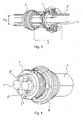
- eine perspektivische Darstellung eines teilweise geöffneten Kabelschlauches mit einem teilweise geöffneten Kabelschlauchabgang,
- Fig. 4
- perspektivische Darstellung eines Kabelschlauchabschnitts mit darin verlaufenden Leitungen,
- Fig. 5
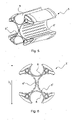
- eine perspektivische Darstellung eines Leiteraufnahmeelements und
- Fig. 6
- eine Draufsicht des Leiteraufnahmeelements.
- Die Figuren enthalten teilweise vereinfachte, schematische Darstellungen. Zum Teil werden für gleiche, aber gegebenenfalls nicht identische Elemente identische Bezugszeichen verwendet. Verschiedene Ansichten gleicher Elemente könnten unterschiedlich skaliert sein.
- In
Figur 1 ist eine Seitenansicht eines Autoladesteckverbinders 1 zu sehen, dessen Gehäuse teilweise geöffnet dargestellt ist. Der Autoladesteckverbinder 1 weist einen Kabelschlauchabgang 2 auf, über welchen die am Autoladesteckverbinder 1 angeschlossenen Leitungen 3, 3', 3", 3‴ in das Gehäuse geführt werden. Die Leitungen 3, 3', 3", 3‴ werden an die Kontaktelemente (nicht gezeigt) des Autoladesteckverbinder 1 angeschlossen. Die Leitungen 3, 3', 3", 3‴ können stromführend sein oder den Autoladesteckverbinder 1 mit Kühlflüssigkeit versorgen. Die Funktionsweise des Autoladesteckverbinders 1 ist nicht erfindungsrelevant und wird daher im Folgenden auch nicht näher beschrieben. - Die Leitungen 3, 3', 3", 3‴ verlaufen in einem Kabelschlauch 4, der teilweise in den Kabelschlauchabgang 2 hineinragt. Die Leitungen 3, 3', 3", 3‴ sind in Aufnahmen 6 eines Leiteraufnahmeelement 5 angeordnet. Das Leiteraufnahmeelement 5 ist wiederum im Kabelschlauch 4 angeordnet. Die Aufnahmen 6 haben einen teilkreisförmigen Querschnitt, dessen Radius an den Querschnitt der jeweiligen Leitung 3, 3', 3", 3‴ angepasst ist.
- Der Außendurchmesser DL des Leiteraufnahmeelements 5 ist nur geringfügig kleiner als der Innendurchmesser DK des Kabelschlauches 4. Man könnte auch sagen, dass der Außendurchmesser DL des Leiteraufnahmeelements 5 an den Innendurchmesser DK des Kabelschlauches 4 angepasst sind. Dadurch kann das Leiteraufnahmeelement 5 in den Kabelschlauch 4 eingeführt werden, ohne dass ein anschließendes Verrutschen befürchtet werden muss.
- Im Bereich des Leiteraufnahmeelements 5 ist außenseitig am Kabelschlauch 4 ein Klemmring 7 vorgesehen. Der Klemmring 7 übt eine radiale Kraft auf den Außenmantel des Kabelschlauches 4 aus. Dadurch wird die Innenseite des Kabelschlauches 4 auf das Leiteraufnahmeelement 5 gepresst.
- In
Figur 2 ist zu erkennen, dass der auf den Kabelschlauch 4 gepresste Klemmring 7 in einer Ausnehmung des Kabelschlauchabgangs 2 angeordnet ist. Dadurch werden die an dem Kabelschlauch 4 wirkenden Zugkräfte abgefangen. - Endseitig ist am Kabelschlauchabgang 2 eine Dichtung 8 angeordnet. Die äußere Form der Dichtung 8 verjüngt sich trichterförmig in Kabelabgangsrichtung. Der Durchmesser der Durchgangsöffnung der Dichtung 8 ist an den Außenradius des Kabelschlauches 4 angepasst. Die Dichtung 8 bietet, neben ihrer Abdichtfunktion gegen das Eindringen von Medien, auch einen so genannten Knickschutz für den Kabelschlauch 4.
- Auch wenn in den Figuren verschiedene Aspekte oder Merkmale der Erfindung jeweils in Kombination gezeigt sind, ist für den Fachmann - soweit nicht anders angegeben - ersichtlich, dass die dargestellten und diskutierten Kombinationen nicht die einzig möglichen sind. Insbesondere können einander entsprechende Einheiten oder Merkmalskomplexe aus unterschiedlichen Ausführungsbeispielen miteinander ausgetauscht werden.
-
- 1
- Autoladesteckverbinder
- 2
- Kabelschlauchabgang
- 3
- Leitungen
- 4
- Kabelschlauch
- 5
- Leiteraufnahmeelement
- 6
- Aufnahme
- 7
- Klemmring
- 8
- Dichtung
- DL
- Außendurchmesser des Leiteraufnahmeelements 5
- DK
- Innendurchmesser des Kabelschlauches 4
Claims (7)
- System bestehend aus einem- Kabelschlauchabgang (2), welcher an einem Autoladesteckverbinder (1) angeformt oder an einer Ladesäule angebracht ist und- einem Kabelschlauch (4) zur Aufnahme von Leitungen (3, 3', 3", 3‴),- wobei innerhalb des Kabelschlauches (4) ein Leiteraufnahmeelement (5) angeordnet ist, welches Aufnahmen (6) für die Leitungen (3, 3', 3", 3‴) aufweist, wobei das Leiteraufnahmeelement (5) eine im Wesentlichen zylinderförmige Grundform aufweist und im Leiteraufnahmeelement (5) axial verlaufende Aufnahmen (6, 6') für die Leitungen (3, 3', 3", 3‴) vorgesehen sinddadurch gekennzeichnet,- dass der Kabelschlauch (4) außenseitig einen Klemmring (7) aufweist, der im Bereich des Leiteraufnahmeelements angeordnet ist [§12, 24 & Fig. 21 und eine radiale Kraft auf den Kabelschlauch (4) ausübt, wodurch der Kabelschlauch (4) auf das Leiteraufnahmeelement (5) gepresst ist,- dass zumindest ein Teil des Kabelschlauches (4) innerhalb des Kabelschlauchabgangs (2) verläuft und- dass der Klemmring (7) in einer Ausnehmung innerhalb des Kabelschlauchabgangs (2) angeordnet ist und dass der Kabelschlauchabgang (2) eine Dichtung (8) aufweist, die endseitig am Kabelschlauchabgang angeordnet ist und das System vor ein Eindringen von Medien wie Staub und Wasser schützt.
- System nach vorstehendem Anspruch
dadurch gekennzeichnet, dass
die Aufnahmen (6, 6') rotationssymmetrisch angeordnet sind. - System nach Anspruch 1
dadurch gekennzeichnet, dass
es sich bei den Aufnahmen (6, 6') um Aussparungen mit einem teilkreisförmigen Querschnitt handelt. - System nach einem der vorstehenden Ansprüchen
dadurch gekennzeichnet, dass
der Außendurchmesser (DL) des Leiteraufnahmeelements (5) an den Innendurchmesser (DK) des Kabelschlauches (4) angepasst ist. - System nach Anspruch 1
dadurch gekennzeichnet, dass
die Dichtung (8) einen außenseitig umlaufenden Steg aufweist, welcher in einer innenliegenden Nut des Kabelschlauchabgangs (2) angeordnet ist. - System nach einem der vorstehenden Ansprüche
dadurch gekennzeichnet, dass
es sich bei den Leitungen (3, 3', 3", 3‴) um elektrische Leitungen und/oder optische Leitungen und/oder kühlflüssigkeitsführende Leitungen handelt. - Autoladesteckverbinder oder Ladesäule mit einem System nach einem der vorstehenden Ansprüche.
Applications Claiming Priority (1)
| Application Number | Priority Date | Filing Date | Title |
|---|---|---|---|
| DE102019101979.6A DE102019101979A1 (de) | 2019-01-28 | 2019-01-28 | Zugentlastung für einen Kabelschlauch |
Publications (2)
| Publication Number | Publication Date |
|---|---|
| EP3686048A1 EP3686048A1 (de) | 2020-07-29 |
| EP3686048B1 true EP3686048B1 (de) | 2022-09-21 |
Family
ID=69159531
Family Applications (1)
| Application Number | Title | Priority Date | Filing Date |
|---|---|---|---|
| EP20000007.3A Active EP3686048B1 (de) | 2019-01-28 | 2020-01-09 | Zugentlastung für einen kabelschlauch |
Country Status (2)
| Country | Link |
|---|---|
| EP (1) | EP3686048B1 (de) |
| DE (1) | DE102019101979A1 (de) |
Cited By (1)
| Publication number | Priority date | Publication date | Assignee | Title |
|---|---|---|---|---|
| EP4506206A3 (de) * | 2023-08-01 | 2025-05-28 | Huawei Digital Power Technologies Co., Ltd. | Ladeverbinder mit flüssigkeitskühlung und ladesäule mit flüssigkeitskühlung |
Citations (7)
| Publication number | Priority date | Publication date | Assignee | Title |
|---|---|---|---|---|
| DE3137067A1 (de) * | 1981-09-17 | 1983-03-24 | Wilhelm 5880 Lüdenscheid Weber | Steckerkupplung |
| DE3820741A1 (de) * | 1988-06-18 | 1989-12-21 | Hilti Ag | Elektrisch betriebenes handwerkzeug |
| EP0663101A1 (de) * | 1993-08-02 | 1995-07-19 | Siemens Ag | Einrichtung und verfahren zur verseilung langgestreckter verseilelemente. |
| US20090167078A1 (en) * | 2005-09-13 | 2009-07-02 | Autonetworks Technologies, Ltd. | Vehicle conductor |
| WO2017064157A1 (de) * | 2015-10-15 | 2017-04-20 | Phoenix Contact E-Mobility Gmbh | Elektrisches kabel mit einer fluidleitung zum kühlen |
| US20180170196A1 (en) * | 2016-12-20 | 2018-06-21 | Suying Electrcnics (Dong Guan) Co., Ltd. | Charging gun with replaceable plug and assembly method thereof |
| EP3103173B1 (de) * | 2014-02-05 | 2019-09-04 | Tesla, Inc. | Kühlung von ladekabel |
Family Cites Families (5)
| Publication number | Priority date | Publication date | Assignee | Title |
|---|---|---|---|---|
| US6396241B1 (en) * | 2000-09-18 | 2002-05-28 | General Motors Corporation | Inductive charging system employing a fluid-cooled transformer coil and transmission cable |
| EP2112721A1 (de) * | 2008-04-23 | 2009-10-28 | Satrotec AG | Dichte Steckerverbindung für Hochspannungskabel im Automobilbau |
| TWI511398B (zh) * | 2013-05-30 | 2015-12-01 | 健和興端子股份有限公司 | Cable locating elements and charging guns using this cable locating element |
| DE102016112306A1 (de) | 2016-07-05 | 2018-01-11 | HARTING Automotive GmbH | Flüssigkeitsgekühltes Kontaktelement |
| DE102017108174A1 (de) | 2017-03-17 | 2018-09-20 | HARTING Automotive GmbH | Autoladesteckverbinder |
-
2019
- 2019-01-28 DE DE102019101979.6A patent/DE102019101979A1/de not_active Withdrawn
-
2020
- 2020-01-09 EP EP20000007.3A patent/EP3686048B1/de active Active
Patent Citations (7)
| Publication number | Priority date | Publication date | Assignee | Title |
|---|---|---|---|---|
| DE3137067A1 (de) * | 1981-09-17 | 1983-03-24 | Wilhelm 5880 Lüdenscheid Weber | Steckerkupplung |
| DE3820741A1 (de) * | 1988-06-18 | 1989-12-21 | Hilti Ag | Elektrisch betriebenes handwerkzeug |
| EP0663101A1 (de) * | 1993-08-02 | 1995-07-19 | Siemens Ag | Einrichtung und verfahren zur verseilung langgestreckter verseilelemente. |
| US20090167078A1 (en) * | 2005-09-13 | 2009-07-02 | Autonetworks Technologies, Ltd. | Vehicle conductor |
| EP3103173B1 (de) * | 2014-02-05 | 2019-09-04 | Tesla, Inc. | Kühlung von ladekabel |
| WO2017064157A1 (de) * | 2015-10-15 | 2017-04-20 | Phoenix Contact E-Mobility Gmbh | Elektrisches kabel mit einer fluidleitung zum kühlen |
| US20180170196A1 (en) * | 2016-12-20 | 2018-06-21 | Suying Electrcnics (Dong Guan) Co., Ltd. | Charging gun with replaceable plug and assembly method thereof |
Cited By (1)
| Publication number | Priority date | Publication date | Assignee | Title |
|---|---|---|---|---|
| EP4506206A3 (de) * | 2023-08-01 | 2025-05-28 | Huawei Digital Power Technologies Co., Ltd. | Ladeverbinder mit flüssigkeitskühlung und ladesäule mit flüssigkeitskühlung |
Also Published As
| Publication number | Publication date |
|---|---|
| EP3686048A1 (de) | 2020-07-29 |
| DE102019101979A1 (de) | 2020-07-30 |
Similar Documents
| Publication | Publication Date | Title |
|---|---|---|
| EP3891851B1 (de) | Anschlusselement zum elektrischen anschliessen einer fluidkühlbaren einzelleitung, fluidkühlbare einzelleitungseinheit und ladekabel | |
| EP2302743B1 (de) | Kabelklemmung mit einem Klemmelement | |
| DE102016112306A1 (de) | Flüssigkeitsgekühltes Kontaktelement | |
| DE102017131352A1 (de) | Leitungsverbinder, elektrische leitungsanordnung sowie herstellverfahren für eine elektrische verbindung | |
| EP3869622A1 (de) | Ladebuchse für ein elektrofahrzeug | |
| DE3787079T2 (de) | Adapter zur Herstellung einer engen Krümmung eines Koaxialkabels. | |
| DE102015211423B4 (de) | Kabelsatzanordnung | |
| WO2021209091A1 (de) | Rundsteckverbinder mit schirmanbindung | |
| EP3869632A1 (de) | Ladebuchse für ein elektrofahrzeug | |
| DE19911253A1 (de) | Elektrisches Verbindungsstück | |
| DE2612262A1 (de) | Drehkupplung zum anschluss einer elektrischen leitung an ein starres gehaeuse | |
| DE202016008631U1 (de) | Flüssigkeitsgekühltes Kontaktelement | |
| DE202017006800U1 (de) | Innenliegende Zugentlastung für einen Steckverbinder | |
| DE1465215A1 (de) | Verbindungsglied fuer Koaxial- oder abgeschirmte Kabel | |
| DE3439156A1 (de) | Hochspannungsbauteil | |
| DE8911885U1 (de) | Verbinderteil eines zweiteiligen elektrischen Verbinders | |
| DE102013113878A1 (de) | Steckverbinder mit Einzeladerabdichtung | |
| WO2001091262A2 (de) | Muffenisolierkörper mit schraubverbinder zur herstellung einer kabelverbindung für mittelspannungs-kunststoffkabel | |
| EP3686048A1 (de) | Zugentlastung für einen kabelschlauch | |
| EP3477777A1 (de) | Elektrische leitung mit schirmausleitung | |
| DE102017129281A1 (de) | Flüssigkeitsgekühltes Kontaktelement | |
| DE102023109580A1 (de) | Hochleistungssteckverbindersystem | |
| DE2609078C3 (de) | Übergangsmuffe | |
| DE102015220685A1 (de) | Zugentlastungselement für eine Leitung, Aufnahmeeinrichtung, Zugentlastungsvorrichtung und Gehäuse | |
| EP4388621B1 (de) | Hochleistungssteckverbinder mit lösbarer kontaktsicherung |
Legal Events
| Date | Code | Title | Description |
|---|---|---|---|
| PUAI | Public reference made under article 153(3) epc to a published international application that has entered the european phase |
Free format text: ORIGINAL CODE: 0009012 |
|
| STAA | Information on the status of an ep patent application or granted ep patent |
Free format text: STATUS: THE APPLICATION HAS BEEN PUBLISHED |
|
| AK | Designated contracting states |
Kind code of ref document: A1 Designated state(s): AL AT BE BG CH CY CZ DE DK EE ES FI FR GB GR HR HU IE IS IT LI LT LU LV MC MK MT NL NO PL PT RO RS SE SI SK SM TR |
|
| AX | Request for extension of the european patent |
Extension state: BA ME |
|
| STAA | Information on the status of an ep patent application or granted ep patent |
Free format text: STATUS: REQUEST FOR EXAMINATION WAS MADE |
|
| 17P | Request for examination filed |
Effective date: 20201210 |
|
| RBV | Designated contracting states (corrected) |
Designated state(s): AL AT BE BG CH CY CZ DE DK EE ES FI FR GB GR HR HU IE IS IT LI LT LU LV MC MK MT NL NO PL PT RO RS SE SI SK SM TR |
|
| STAA | Information on the status of an ep patent application or granted ep patent |
Free format text: STATUS: EXAMINATION IS IN PROGRESS |
|
| 17Q | First examination report despatched |
Effective date: 20210323 |
|
| GRAP | Despatch of communication of intention to grant a patent |
Free format text: ORIGINAL CODE: EPIDOSNIGR1 |
|
| STAA | Information on the status of an ep patent application or granted ep patent |
Free format text: STATUS: GRANT OF PATENT IS INTENDED |
|
| INTG | Intention to grant announced |
Effective date: 20220628 |
|
| GRAS | Grant fee paid |
Free format text: ORIGINAL CODE: EPIDOSNIGR3 |
|
| GRAA | (expected) grant |
Free format text: ORIGINAL CODE: 0009210 |
|
| STAA | Information on the status of an ep patent application or granted ep patent |
Free format text: STATUS: THE PATENT HAS BEEN GRANTED |
|
| AK | Designated contracting states |
Kind code of ref document: B1 Designated state(s): AL AT BE BG CH CY CZ DE DK EE ES FI FR GB GR HR HU IE IS IT LI LT LU LV MC MK MT NL NO PL PT RO RS SE SI SK SM TR |
|
| REG | Reference to a national code |
Ref country code: GB Ref legal event code: FG4D Free format text: NOT ENGLISH |
|
| REG | Reference to a national code |
Ref country code: CH Ref legal event code: EP |
|
| REG | Reference to a national code |
Ref country code: IE Ref legal event code: FG4D Free format text: LANGUAGE OF EP DOCUMENT: GERMAN |
|
| REG | Reference to a national code |
Ref country code: DE Ref legal event code: R096 Ref document number: 502020001709 Country of ref document: DE |
|
| REG | Reference to a national code |
Ref country code: AT Ref legal event code: REF Ref document number: 1519797 Country of ref document: AT Kind code of ref document: T Effective date: 20221015 |
|
| REG | Reference to a national code |
Ref country code: LT Ref legal event code: MG9D |
|
| REG | Reference to a national code |
Ref country code: NL Ref legal event code: MP Effective date: 20220921 |
|
| PG25 | Lapsed in a contracting state [announced via postgrant information from national office to epo] |
Ref country code: SE Free format text: LAPSE BECAUSE OF FAILURE TO SUBMIT A TRANSLATION OF THE DESCRIPTION OR TO PAY THE FEE WITHIN THE PRESCRIBED TIME-LIMIT Effective date: 20220921 Ref country code: RS Free format text: LAPSE BECAUSE OF FAILURE TO SUBMIT A TRANSLATION OF THE DESCRIPTION OR TO PAY THE FEE WITHIN THE PRESCRIBED TIME-LIMIT Effective date: 20220921 Ref country code: NO Free format text: LAPSE BECAUSE OF FAILURE TO SUBMIT A TRANSLATION OF THE DESCRIPTION OR TO PAY THE FEE WITHIN THE PRESCRIBED TIME-LIMIT Effective date: 20221221 Ref country code: LV Free format text: LAPSE BECAUSE OF FAILURE TO SUBMIT A TRANSLATION OF THE DESCRIPTION OR TO PAY THE FEE WITHIN THE PRESCRIBED TIME-LIMIT Effective date: 20220921 Ref country code: LT Free format text: LAPSE BECAUSE OF FAILURE TO SUBMIT A TRANSLATION OF THE DESCRIPTION OR TO PAY THE FEE WITHIN THE PRESCRIBED TIME-LIMIT Effective date: 20220921 Ref country code: FI Free format text: LAPSE BECAUSE OF FAILURE TO SUBMIT A TRANSLATION OF THE DESCRIPTION OR TO PAY THE FEE WITHIN THE PRESCRIBED TIME-LIMIT Effective date: 20220921 |
|
| PG25 | Lapsed in a contracting state [announced via postgrant information from national office to epo] |
Ref country code: HR Free format text: LAPSE BECAUSE OF FAILURE TO SUBMIT A TRANSLATION OF THE DESCRIPTION OR TO PAY THE FEE WITHIN THE PRESCRIBED TIME-LIMIT Effective date: 20220921 Ref country code: GR Free format text: LAPSE BECAUSE OF FAILURE TO SUBMIT A TRANSLATION OF THE DESCRIPTION OR TO PAY THE FEE WITHIN THE PRESCRIBED TIME-LIMIT Effective date: 20221222 |
|
| PG25 | Lapsed in a contracting state [announced via postgrant information from national office to epo] |
Ref country code: SM Free format text: LAPSE BECAUSE OF FAILURE TO SUBMIT A TRANSLATION OF THE DESCRIPTION OR TO PAY THE FEE WITHIN THE PRESCRIBED TIME-LIMIT Effective date: 20220921 Ref country code: RO Free format text: LAPSE BECAUSE OF FAILURE TO SUBMIT A TRANSLATION OF THE DESCRIPTION OR TO PAY THE FEE WITHIN THE PRESCRIBED TIME-LIMIT Effective date: 20220921 Ref country code: PT Free format text: LAPSE BECAUSE OF FAILURE TO SUBMIT A TRANSLATION OF THE DESCRIPTION OR TO PAY THE FEE WITHIN THE PRESCRIBED TIME-LIMIT Effective date: 20230123 Ref country code: ES Free format text: LAPSE BECAUSE OF FAILURE TO SUBMIT A TRANSLATION OF THE DESCRIPTION OR TO PAY THE FEE WITHIN THE PRESCRIBED TIME-LIMIT Effective date: 20220921 Ref country code: CZ Free format text: LAPSE BECAUSE OF FAILURE TO SUBMIT A TRANSLATION OF THE DESCRIPTION OR TO PAY THE FEE WITHIN THE PRESCRIBED TIME-LIMIT Effective date: 20220921 |
|
| PG25 | Lapsed in a contracting state [announced via postgrant information from national office to epo] |
Ref country code: SK Free format text: LAPSE BECAUSE OF FAILURE TO SUBMIT A TRANSLATION OF THE DESCRIPTION OR TO PAY THE FEE WITHIN THE PRESCRIBED TIME-LIMIT Effective date: 20220921 Ref country code: PL Free format text: LAPSE BECAUSE OF FAILURE TO SUBMIT A TRANSLATION OF THE DESCRIPTION OR TO PAY THE FEE WITHIN THE PRESCRIBED TIME-LIMIT Effective date: 20220921 Ref country code: IS Free format text: LAPSE BECAUSE OF FAILURE TO SUBMIT A TRANSLATION OF THE DESCRIPTION OR TO PAY THE FEE WITHIN THE PRESCRIBED TIME-LIMIT Effective date: 20230121 Ref country code: EE Free format text: LAPSE BECAUSE OF FAILURE TO SUBMIT A TRANSLATION OF THE DESCRIPTION OR TO PAY THE FEE WITHIN THE PRESCRIBED TIME-LIMIT Effective date: 20220921 |
|
| REG | Reference to a national code |
Ref country code: DE Ref legal event code: R097 Ref document number: 502020001709 Country of ref document: DE |
|
| PG25 | Lapsed in a contracting state [announced via postgrant information from national office to epo] |
Ref country code: NL Free format text: LAPSE BECAUSE OF FAILURE TO SUBMIT A TRANSLATION OF THE DESCRIPTION OR TO PAY THE FEE WITHIN THE PRESCRIBED TIME-LIMIT Effective date: 20220921 Ref country code: AL Free format text: LAPSE BECAUSE OF FAILURE TO SUBMIT A TRANSLATION OF THE DESCRIPTION OR TO PAY THE FEE WITHIN THE PRESCRIBED TIME-LIMIT Effective date: 20220921 |
|
| P01 | Opt-out of the competence of the unified patent court (upc) registered |
Effective date: 20230603 |
|
| PLBE | No opposition filed within time limit |
Free format text: ORIGINAL CODE: 0009261 |
|
| STAA | Information on the status of an ep patent application or granted ep patent |
Free format text: STATUS: NO OPPOSITION FILED WITHIN TIME LIMIT |
|
| PG25 | Lapsed in a contracting state [announced via postgrant information from national office to epo] |
Ref country code: DK Free format text: LAPSE BECAUSE OF FAILURE TO SUBMIT A TRANSLATION OF THE DESCRIPTION OR TO PAY THE FEE WITHIN THE PRESCRIBED TIME-LIMIT Effective date: 20220921 |
|
| 26N | No opposition filed |
Effective date: 20230622 |
|
| PG25 | Lapsed in a contracting state [announced via postgrant information from national office to epo] |
Ref country code: SI Free format text: LAPSE BECAUSE OF FAILURE TO SUBMIT A TRANSLATION OF THE DESCRIPTION OR TO PAY THE FEE WITHIN THE PRESCRIBED TIME-LIMIT Effective date: 20220921 |
|
| REG | Reference to a national code |
Ref country code: CH Ref legal event code: PL |
|
| PG25 | Lapsed in a contracting state [announced via postgrant information from national office to epo] |
Ref country code: LU Free format text: LAPSE BECAUSE OF NON-PAYMENT OF DUE FEES Effective date: 20230109 |
|
| REG | Reference to a national code |
Ref country code: BE Ref legal event code: MM Effective date: 20230131 |
|
| PG25 | Lapsed in a contracting state [announced via postgrant information from national office to epo] |
Ref country code: LI Free format text: LAPSE BECAUSE OF NON-PAYMENT OF DUE FEES Effective date: 20230131 Ref country code: CH Free format text: LAPSE BECAUSE OF NON-PAYMENT OF DUE FEES Effective date: 20230131 |
|
| PG25 | Lapsed in a contracting state [announced via postgrant information from national office to epo] |
Ref country code: BE Free format text: LAPSE BECAUSE OF NON-PAYMENT OF DUE FEES Effective date: 20230131 |
|
| PG25 | Lapsed in a contracting state [announced via postgrant information from national office to epo] |
Ref country code: IE Free format text: LAPSE BECAUSE OF NON-PAYMENT OF DUE FEES Effective date: 20230109 |
|
| PG25 | Lapsed in a contracting state [announced via postgrant information from national office to epo] |
Ref country code: IT Free format text: LAPSE BECAUSE OF FAILURE TO SUBMIT A TRANSLATION OF THE DESCRIPTION OR TO PAY THE FEE WITHIN THE PRESCRIBED TIME-LIMIT Effective date: 20220921 |
|
| PG25 | Lapsed in a contracting state [announced via postgrant information from national office to epo] |
Ref country code: MC Free format text: LAPSE BECAUSE OF FAILURE TO SUBMIT A TRANSLATION OF THE DESCRIPTION OR TO PAY THE FEE WITHIN THE PRESCRIBED TIME-LIMIT Effective date: 20220921 |
|
| PG25 | Lapsed in a contracting state [announced via postgrant information from national office to epo] |
Ref country code: MC Free format text: LAPSE BECAUSE OF FAILURE TO SUBMIT A TRANSLATION OF THE DESCRIPTION OR TO PAY THE FEE WITHIN THE PRESCRIBED TIME-LIMIT Effective date: 20220921 |
|
| PG25 | Lapsed in a contracting state [announced via postgrant information from national office to epo] |
Ref country code: BG Free format text: LAPSE BECAUSE OF FAILURE TO SUBMIT A TRANSLATION OF THE DESCRIPTION OR TO PAY THE FEE WITHIN THE PRESCRIBED TIME-LIMIT Effective date: 20220921 |
|
| PG25 | Lapsed in a contracting state [announced via postgrant information from national office to epo] |
Ref country code: BG Free format text: LAPSE BECAUSE OF FAILURE TO SUBMIT A TRANSLATION OF THE DESCRIPTION OR TO PAY THE FEE WITHIN THE PRESCRIBED TIME-LIMIT Effective date: 20220921 |
|
| PGFP | Annual fee paid to national office [announced via postgrant information from national office to epo] |
Ref country code: AT Payment date: 20250417 Year of fee payment: 5 |
|
| PG25 | Lapsed in a contracting state [announced via postgrant information from national office to epo] |
Ref country code: CY Free format text: LAPSE BECAUSE OF FAILURE TO SUBMIT A TRANSLATION OF THE DESCRIPTION OR TO PAY THE FEE WITHIN THE PRESCRIBED TIME-LIMIT; INVALID AB INITIO Effective date: 20200109 |
|
| PG25 | Lapsed in a contracting state [announced via postgrant information from national office to epo] |
Ref country code: HU Free format text: LAPSE BECAUSE OF FAILURE TO SUBMIT A TRANSLATION OF THE DESCRIPTION OR TO PAY THE FEE WITHIN THE PRESCRIBED TIME-LIMIT; INVALID AB INITIO Effective date: 20200109 |
|
| PG25 | Lapsed in a contracting state [announced via postgrant information from national office to epo] |
Ref country code: TR Free format text: LAPSE BECAUSE OF FAILURE TO SUBMIT A TRANSLATION OF THE DESCRIPTION OR TO PAY THE FEE WITHIN THE PRESCRIBED TIME-LIMIT Effective date: 20220921 |
|
| REG | Reference to a national code |
Ref country code: AT Ref legal event code: MM01 Ref document number: 1519797 Country of ref document: AT Kind code of ref document: T Effective date: 20250109 |
|
| PGFP | Annual fee paid to national office [announced via postgrant information from national office to epo] |
Ref country code: GB Payment date: 20260126 Year of fee payment: 7 |
|
| PGFP | Annual fee paid to national office [announced via postgrant information from national office to epo] |
Ref country code: DE Payment date: 20260127 Year of fee payment: 7 |
|
| PG25 | Lapsed in a contracting state [announced via postgrant information from national office to epo] |
Ref country code: AT Free format text: LAPSE BECAUSE OF NON-PAYMENT OF DUE FEES Effective date: 20250109 |
|
| PGFP | Annual fee paid to national office [announced via postgrant information from national office to epo] |
Ref country code: FR Payment date: 20260127 Year of fee payment: 7 |