EP3683392A1 - Verfahren zum montieren eines türantriebs und türantrieb - Google Patents
Verfahren zum montieren eines türantriebs und türantrieb Download PDFInfo
- Publication number
- EP3683392A1 EP3683392A1 EP19152192.1A EP19152192A EP3683392A1 EP 3683392 A1 EP3683392 A1 EP 3683392A1 EP 19152192 A EP19152192 A EP 19152192A EP 3683392 A1 EP3683392 A1 EP 3683392A1
- Authority
- EP
- European Patent Office
- Prior art keywords
- door
- lever
- axle
- mounting
- unit
- Prior art date
- Legal status (The legal status is an assumption and is not a legal conclusion. Google has not performed a legal analysis and makes no representation as to the accuracy of the status listed.)
- Granted
Links
Images

Classifications
-
- E—FIXED CONSTRUCTIONS
- E05—LOCKS; KEYS; WINDOW OR DOOR FITTINGS; SAFES
- E05F—DEVICES FOR MOVING WINGS INTO OPEN OR CLOSED POSITION; CHECKS FOR WINGS; WING FITTINGS NOT OTHERWISE PROVIDED FOR, CONCERNED WITH THE FUNCTIONING OF THE WING
- E05F15/00—Power-operated mechanisms for wings
- E05F15/60—Power-operated mechanisms for wings using electrical actuators
-
- E—FIXED CONSTRUCTIONS
- E05—LOCKS; KEYS; WINDOW OR DOOR FITTINGS; SAFES
- E05F—DEVICES FOR MOVING WINGS INTO OPEN OR CLOSED POSITION; CHECKS FOR WINGS; WING FITTINGS NOT OTHERWISE PROVIDED FOR, CONCERNED WITH THE FUNCTIONING OF THE WING
- E05F1/00—Closers or openers for wings, not otherwise provided for in this subclass
- E05F1/08—Closers or openers for wings, not otherwise provided for in this subclass spring-actuated, e.g. for horizontally sliding wings
-
- E—FIXED CONSTRUCTIONS
- E05—LOCKS; KEYS; WINDOW OR DOOR FITTINGS; SAFES
- E05F—DEVICES FOR MOVING WINGS INTO OPEN OR CLOSED POSITION; CHECKS FOR WINGS; WING FITTINGS NOT OTHERWISE PROVIDED FOR, CONCERNED WITH THE FUNCTIONING OF THE WING
- E05F1/00—Closers or openers for wings, not otherwise provided for in this subclass
- E05F1/08—Closers or openers for wings, not otherwise provided for in this subclass spring-actuated, e.g. for horizontally sliding wings
- E05F1/10—Closers or openers for wings, not otherwise provided for in this subclass spring-actuated, e.g. for horizontally sliding wings for swinging wings, e.g. counterbalance
-
- E—FIXED CONSTRUCTIONS
- E05—LOCKS; KEYS; WINDOW OR DOOR FITTINGS; SAFES
- E05F—DEVICES FOR MOVING WINGS INTO OPEN OR CLOSED POSITION; CHECKS FOR WINGS; WING FITTINGS NOT OTHERWISE PROVIDED FOR, CONCERNED WITH THE FUNCTIONING OF THE WING
- E05F15/00—Power-operated mechanisms for wings
- E05F15/50—Power-operated mechanisms for wings using fluid-pressure actuators
-
- E—FIXED CONSTRUCTIONS
- E05—LOCKS; KEYS; WINDOW OR DOOR FITTINGS; SAFES
- E05F—DEVICES FOR MOVING WINGS INTO OPEN OR CLOSED POSITION; CHECKS FOR WINGS; WING FITTINGS NOT OTHERWISE PROVIDED FOR, CONCERNED WITH THE FUNCTIONING OF THE WING
- E05F15/00—Power-operated mechanisms for wings
- E05F15/60—Power-operated mechanisms for wings using electrical actuators
- E05F15/603—Power-operated mechanisms for wings using electrical actuators using rotary electromotors
- E05F15/611—Power-operated mechanisms for wings using electrical actuators using rotary electromotors for swinging wings
- E05F15/63—Power-operated mechanisms for wings using electrical actuators using rotary electromotors for swinging wings operated by swinging arms
-
- E—FIXED CONSTRUCTIONS
- E05—LOCKS; KEYS; WINDOW OR DOOR FITTINGS; SAFES
- E05F—DEVICES FOR MOVING WINGS INTO OPEN OR CLOSED POSITION; CHECKS FOR WINGS; WING FITTINGS NOT OTHERWISE PROVIDED FOR, CONCERNED WITH THE FUNCTIONING OF THE WING
- E05F3/00—Closers or openers with braking devices, e.g. checks; Construction of pneumatic or liquid braking devices
- E05F3/04—Closers or openers with braking devices, e.g. checks; Construction of pneumatic or liquid braking devices with liquid piston brakes
- E05F3/10—Closers or openers with braking devices, e.g. checks; Construction of pneumatic or liquid braking devices with liquid piston brakes with a spring, other than a torsion spring, and a piston, the axes of which are the same or lie in the same direction
-
- E—FIXED CONSTRUCTIONS
- E05—LOCKS; KEYS; WINDOW OR DOOR FITTINGS; SAFES
- E05F—DEVICES FOR MOVING WINGS INTO OPEN OR CLOSED POSITION; CHECKS FOR WINGS; WING FITTINGS NOT OTHERWISE PROVIDED FOR, CONCERNED WITH THE FUNCTIONING OF THE WING
- E05F3/00—Closers or openers with braking devices, e.g. checks; Construction of pneumatic or liquid braking devices
- E05F3/22—Additional arrangements for closers, e.g. for holding the wing in opened or other position
- E05F3/227—Additional arrangements for closers, e.g. for holding the wing in opened or other position mounted at the top of wings, e.g. details related to closer housings, covers, end caps or rails therefor
-
- E—FIXED CONSTRUCTIONS
- E05—LOCKS; KEYS; WINDOW OR DOOR FITTINGS; SAFES
- E05Y—INDEXING SCHEME ASSOCIATED WITH SUBCLASSES E05D AND E05F, RELATING TO CONSTRUCTION ELEMENTS, ELECTRIC CONTROL, POWER SUPPLY, POWER SIGNAL OR TRANSMISSION, USER INTERFACES, MOUNTING OR COUPLING, DETAILS, ACCESSORIES, AUXILIARY OPERATIONS NOT OTHERWISE PROVIDED FOR, APPLICATION THEREOF
- E05Y2600/00—Mounting or coupling arrangements for elements provided for in this subclass
- E05Y2600/50—Mounting methods; Positioning
-
- E—FIXED CONSTRUCTIONS
- E05—LOCKS; KEYS; WINDOW OR DOOR FITTINGS; SAFES
- E05Y—INDEXING SCHEME ASSOCIATED WITH SUBCLASSES E05D AND E05F, RELATING TO CONSTRUCTION ELEMENTS, ELECTRIC CONTROL, POWER SUPPLY, POWER SIGNAL OR TRANSMISSION, USER INTERFACES, MOUNTING OR COUPLING, DETAILS, ACCESSORIES, AUXILIARY OPERATIONS NOT OTHERWISE PROVIDED FOR, APPLICATION THEREOF
- E05Y2600/00—Mounting or coupling arrangements for elements provided for in this subclass
- E05Y2600/50—Mounting methods; Positioning
- E05Y2600/56—Positioning, e.g. re-positioning, or pre-mounting
-
- E—FIXED CONSTRUCTIONS
- E05—LOCKS; KEYS; WINDOW OR DOOR FITTINGS; SAFES
- E05Y—INDEXING SCHEME ASSOCIATED WITH SUBCLASSES E05D AND E05F, RELATING TO CONSTRUCTION ELEMENTS, ELECTRIC CONTROL, POWER SUPPLY, POWER SIGNAL OR TRANSMISSION, USER INTERFACES, MOUNTING OR COUPLING, DETAILS, ACCESSORIES, AUXILIARY OPERATIONS NOT OTHERWISE PROVIDED FOR, APPLICATION THEREOF
- E05Y2800/00—Details, accessories and auxiliary operations not otherwise provided for
- E05Y2800/15—Applicability
- E05Y2800/17—Universally applicable
- E05Y2800/172—Universally applicable on different wing or frame locations
-
- E—FIXED CONSTRUCTIONS
- E05—LOCKS; KEYS; WINDOW OR DOOR FITTINGS; SAFES
- E05Y—INDEXING SCHEME ASSOCIATED WITH SUBCLASSES E05D AND E05F, RELATING TO CONSTRUCTION ELEMENTS, ELECTRIC CONTROL, POWER SUPPLY, POWER SIGNAL OR TRANSMISSION, USER INTERFACES, MOUNTING OR COUPLING, DETAILS, ACCESSORIES, AUXILIARY OPERATIONS NOT OTHERWISE PROVIDED FOR, APPLICATION THEREOF
- E05Y2800/00—Details, accessories and auxiliary operations not otherwise provided for
- E05Y2800/74—Specific positions
- E05Y2800/742—Specific positions abnormal
-
- E—FIXED CONSTRUCTIONS
- E05—LOCKS; KEYS; WINDOW OR DOOR FITTINGS; SAFES
- E05Y—INDEXING SCHEME ASSOCIATED WITH SUBCLASSES E05D AND E05F, RELATING TO CONSTRUCTION ELEMENTS, ELECTRIC CONTROL, POWER SUPPLY, POWER SIGNAL OR TRANSMISSION, USER INTERFACES, MOUNTING OR COUPLING, DETAILS, ACCESSORIES, AUXILIARY OPERATIONS NOT OTHERWISE PROVIDED FOR, APPLICATION THEREOF
- E05Y2900/00—Application of doors, windows, wings or fittings thereof
- E05Y2900/10—Application of doors, windows, wings or fittings thereof for buildings or parts thereof
- E05Y2900/13—Type of wing
- E05Y2900/132—Doors
Definitions
- the present invention relates to a method for mounting a door drive comprising a door actuator, a fastening device and a lever mechanism for movably mounting the door actuator on the fastening device between a closed position and an open position.
- An actuating unit of the door operator is designed to move an axis device of the door operator.
- the invention further relates to a door drive.
- a door drive serves, for example, to assist opening and / or closing of a door and preferably extends the functional scope of the door with a lockable opening position.
- Door drives usually consist of a device on the frame of the door, a device on the door leaf and a lever mechanism for movable mounting and connection of the device on the door frame with the device on the door leaf.
- Such a door drive uses an actuating unit to support the movement of the door, which acts on the door with a force.
- spring force devices and motor devices are known from the prior art.
- Door drives are also known which can be used for doors with different hinge positions, for example on the right or left on the side sections of a door.
- the lever mechanism When installing door drives with an actuation unit as well as when installing door drives without an actuation unit, the lever mechanism must be fitted with the Devices on the door frame and / or on the door leaf are connected and attached.
- the movable, usually rotatable or arranged in rails elements of the devices on the door frame and / or on the door leaf must be arranged and / or rotated accordingly in order to enable a connection and attachment to the lever mechanism.
- Such positioning of the elements is prone to errors and can lead to incorrect assembly and thus to expensive rework.
- the publication EP 3 309 339 A1 discloses a solution for the topics described above with a drive for a wing of a door or a window with an exclusively mechanical securing of the movable elements by locking with a bolt for improved assembly of the lever mechanism. It is the object of the invention to at least partially remedy the disadvantages of door drives described above. In particular, the object of the invention is to provide a method for assembling a door drive and a door drive, in which the susceptibility to assembly errors and the time required for assembly are reduced in a particularly simple and inexpensive manner.
- the actuation unit is designed as a motor unit and the movement of the axis device of the door operator is carried out by the motor unit.
- a motor unit for moving the axis device of the door actuator is an advantageous further development of the method according to the invention, since a motor unit has a constant, in particular continuous, application of force for the movement of the door leaf between at least one opening position and at least one closing position.
- a motor unit can be further controlled extensively and stopped in a defined manner at any time or in any area of the movement. The speed of the movement can be influenced and controlled in a defined manner by a motor unit, so that an accelerated movement of the axis device and a slowed movement of the axis device is made possible by a motor unit.
- the actuating unit is designed as a clamping force unit and the movement of the axis device of the door operator is carried out by the clamping force unit.
- a clamping force unit enables a particularly cost-effective solution to the application of force for the movement of the axis device.
- a tensioning force unit applies a force for the movement of a door between an open position and a closed position in a particularly advantageous manner, since, for example, a decrease in the force is made possible with increasing relaxation of the tensioning force unit and, consequently, the door becomes less strongly towards the end of a movement between an open position and a closed position a force is applied and thus a loud closing or jerky opening of the door and / or the window is avoided.
- the clamping force curve of a clamping force unit can also be constructed using simple construction methods Means are influenced and thus the opening or closing movement of a door and / or a window are advantageously influenced.
- a clamping force of a clamping force unit can be applied in addition or as an alternative to a force of a motor unit for the movement of the axis device.
- the actuating unit moves the axle device of the door operator into a first lever mounting position when a first axle lever of the axle device is arranged and fixed and the actuating unit moves the axle device of the door operator into a second lever mounting position when a second axle lever the axis device is arranged and fixed.
- the opening or closing movement can be determined, for example, by positioning the joints.
- a door opening on the right essentially represents, for example, a reflection on a vertical plane of a door opening on the left.
- the door drive must be coordinated with the movement of the door.
- first axle lever and a second axle lever can be designed differently or identically.
- the first axle lever and the second axle lever can be a structural component of the axle device or the lever mechanism.
- the lever mounting positions of the axle device can be arranged in particular in the case of a rotatable axle device between 0 ° and 180 °, particularly advantageously at 0 °, 90 ° and / or 115 °.
- the lever mounting positions can advantageously be opposite one another, that is to say they can be spaced 180 ° apart, for cost-effective production and simple, less error-prone assembly.
- a Method according to the invention to mount two structurally identical door drives for two different door movements of two doors in that a first axle lever is arranged and fixed, for example on the axle device in a first lever mounting position and a second axle lever is arranged and fixed, for example on the other axle device in a second lever mounting position.
- a method according to the invention can also be developed in such a way that the actuating unit moves the axle device of the door operator into a first lever mounting position or a second lever mounting position, on the basis of a recognition of the first axle lever or the second axle lever by a recognition unit of the door drive.
- a method according to the invention is particularly advantageous if the lever mounting position is selected directly on the basis of a recognized axle lever. This further reduces the susceptibility to errors during assembly and advantageously accelerates assembly.
- a detection unit can be at least partially automated and / or at least partially manual.
- the actuating unit moves the axis device of the door operator into a first lever mounting position or a second lever mounting position, based on a switch position of a switch of the door drive.
- a switch for setting or selecting the lever mounting position is a cost-effective way to reduce the susceptibility to errors when installing a door drive.
- a switch is in particular a manual switch which can be operated by a user.
- a switch is particularly advantageously designed as a rotary switch with angle information. With such a switch, a user can select the desired position of the axle device in a lever mounting position and an actuation unit moves the axle device accordingly into the selected lever mounting position. A faulty one Positioning of the axis device when installing the door drive is thus avoided.
- a method according to the invention can preferably be further developed such that the door drive for the power supply to the door operator, in particular the motor unit of the door operator, has a building power connection and / or an energy store.
- a door drive, in particular a door drive with a motor may require a power supply for executing the movement, for the lighting device and / or for further devices of the door drive.
- the energy supply can be provided by an energy store and / or by a building power connection.
- a method according to the invention can particularly preferably be designed such that the door drive has a computer unit with a memory unit for controlling the actuation unit, the memory unit being designed for storing at least one lever mounting position.
- a computer unit can advantageously and extensively control an actuation unit.
- a computer unit advantageously extends the functional scope of a door drive and can be controlled and operated in a wired and / or wireless manner.
- the computer unit is preferably connected to the actuation unit in a wired manner and can move the axis device into the various lever-mounting positions via the actuation unit. Such a further developed method enables the movement of the axis device to be controlled by a computer unit.
- a storage unit extends the functional scope of the computing unit advantageous and enables storage of at least one lever mounting position that can be approached by the computer unit or by the axle device.
- a door drive having a door actuator with a mounting section for fastening to a counter-mounting section of a door, a fastening device for mounting on a counter-mounting section of the door and a lever mechanism with a first end and a second end movable mounting of the door operator on the fastening device between a closed position and an open position, the fastening device being arranged at the first end of the lever mechanism and an axle device of the door actuator at a second end of the lever mechanism, and an actuating unit for moving the axle device.
- a door drive according to the second aspect is designed for use in the method according to the first aspect, a door drive according to the second aspect of the invention has the same advantages as have been described in detail with respect to the method according to the first aspect and vice versa .
- the actuation unit is designed as a motor unit and / or as a clamping force unit.
- a motor unit for moving the axis device of the door actuator is an advantageous further development of the door drive according to the invention, since a motor unit has a constant, in particular continuous, application of force for the movement of the door frame between at least one opening position and at least one closing position.
- a motor unit can be further controlled extensively and stopped in a defined manner at any time or in any area of the movement.
- the speed of the movement can be influenced and controlled in a defined manner by a motor unit, so that an accelerated movement of the axis device and a slowed movement of the axis device is made possible by a motor unit.
- a clamping force unit enables a particularly cost-effective solution to the application of force for the movement of the axis device.
- the axis device can be moved at least from a closed position via at least one lever-mounted position to an open position.
- An axis device can be moved between an open position and a closed position by a rotational movement and / or a movement along an axis and / or by another movement.
- at least one lever mounting position is arranged between the closed position and the open position.
- At least two lever mounting positions are preferably arranged between the closed position and the open position.
- the door actuator has at least one stop for the movement of the axle device and / or the lever mechanism at at least one of the closed position, the lever mounting position and / or the opening position.
- the movement of the axis device can additionally be influenced by at least one stop.
- a stop limits or stops the movement of the axis device at at least one point in the movement sequence. Stopping the sequence of movements can be temporary or permanent, that is to say the movement can be briefly suspended at the point at which the stop stops the movement in order to continue in the same direction, for example after overcoming resistance of the stop. Overcoming the resistance may require user intervention or may be performed automatically by the door operator. In the context of the invention, briefly means a few seconds to half a minute.
- At least one stop is an advantageous further development of the door drive according to the invention, since the at least one stop represents a cost-effective way of influencing the movement sequence of the door drive.
- a door drive according to the invention can also be further developed such that the axis device of the door operator can be moved by the actuating unit at least into a first lever mounting position and at least a second lever mounting position.
- a door drive according to the invention enables two identical door drives for two different door movements of two doors to be installed, for example by arranging and fixing a first axle lever on the axle device in a first lever mounting position and arranging and fixing a second axle lever on the other axle device in a second lever mounting position, for example .
- a door drive it can further be provided that the axle device of the door operator can be moved by the actuating unit into a first lever mounting position or a second lever mounting position, on the basis of recognition of the first axle lever or the second axle lever by a recognition unit of the door drive.
- a door drive according to the invention is particularly advantageous if the lever installation position is selected directly on the basis of a recognized axle lever. This further reduces the susceptibility to errors during assembly and advantageously accelerates assembly.
- a detection unit can be at least partially automated and / or at least partially manual.
- a door drive according to the invention can preferably be further developed in such a way that the axis device of the door actuator can be moved into a first lever mounting position or a second lever mounting position by the actuating unit is based on a switch position of a manual switch of the door operator.
- a switch for setting or selecting the lever mounting position is a cost-effective way to reduce the susceptibility to errors when installing a door drive.
- a switch is in particular a manual switch which can be operated by a user.
- a switch is particularly advantageously designed as a rotary switch with angle information. With such a switch, a user can select the desired position of the axle device in a lever mounting position and an actuation unit moves the axle device accordingly into the selected lever mounting position. Incorrect positioning of the axis device when installing the door drive is consequently avoided.
- a door drive according to the invention can particularly preferably be designed such that a computer unit of the door drive is designed with a memory unit for controlling the actuation unit, the memory unit being designed in particular for storing lever mounting positions.
- a computer unit advantageously extends the functional scope of a door drive and can be controlled and operated in a wired and / or wireless manner.
- the computer unit is preferably connected to the actuation unit in a wired manner and can move the axis device into the various lever-mounting positions via the actuation unit.
- a door drive developed in this way enables the movement of the axis device to be controlled by a computer unit.
- a memory unit advantageously extends the functional scope of the computer unit and enables storage of at least one lever mounting position that can be approached by the computer unit or by the axle device.
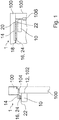
- Fig. 1 shows a side view and a front view of a door drive 1 with a door actuator 10, a fastening device 14 and a lever mechanism 16 for the movable mounting of the door operator 10 on the Fastening device 14 between a closed position SP (not shown) and an open position OP (not shown).
- the fastening device 14 is fastened to a counter-fastening section 104 of the frame of a door 100.
- the door operator 10 has a mounting portion 12 that is attached to a counter-mounting portion 102 on the leaf of the door.
- a first end 18 of the lever mechanism 16 is arranged and fixed on the fastening device 14.
- a second end 20 of the lever mechanism 16 is arranged and fixed on the axle device 22 of the door operator 10.
- the door 100 has at least one door hinge 106 on the right side and is consequently a right-opening door 100 in the sense of the invention.
- a first axle lever 24 of the lever mechanism 16 has been mounted on the axle device 22 in a first lever mounting position 30 (not shown).
- the fastening device 14 is designed as a rail with a lateral extension in the front view.
- a door drive 1 designed in this way makes it possible, in a particularly simple and inexpensive manner, to reduce the susceptibility to errors in assembly and to reduce the time required for assembly.
- Fig. 2 shows a side view and a front view of a door drive 1 with a door operator 10 of a fastening device 14 and a lever mechanism 16 for movably mounting the door operator 10 on the fastening device 14 between a closed position SP (not shown) and an open position OP (not shown).
- the fastening device 14 is fastened to a counter fastening section 104 on the leaf of a door 100.
- the door operator 10 has a mounting section 12 which is fastened to a counter-mounting section 102 of the frame of the door.
- a first end 18 of the lever mechanism 16 is arranged on the fastening device 14 and fixed or mounted.
- a second end 20 of the lever mechanism 16 is arranged on the axis device 22 of the door operator 10 and fixed or mounted.
- the door 100 has at least one door hinge 106 on the left side and is consequently a left-opening door 100 in the sense of the invention.
- a second Axle lever 26 of the lever mechanism 16 has been mounted on the axle device 22 in a second lever mounting position 32 (not shown).
- a door drive 1 designed in this way makes it possible, in a particularly simple and inexpensive manner, to reduce the susceptibility to errors in assembly and to reduce the time required for assembly.
- the Figs. 1 and 2nd clearly show how two structurally identical door drives 1 of the invention can be used for two different door movements of two doors 100, for example by mounting a first axle lever 24 on the axle device 22 in a first lever mounting position 30 (not shown) (see Fig.
- a second axle lever 26 is mounted, for example, on the other axle device 22 in a second lever mounting position 32 (not shown) (see Fig. 2 ). Also show the Figs. 1 and 2nd that the fastening unit 14 and the door actuator 10 can each be mounted both on the leaf of the door 100 and on the frame of the door 100 or on an adjacent wall and / or ceiling.
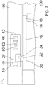
- Fig. 3 shows a front view of a door drive 1 with a door operator 10 of a fastening device 14 and a lever mechanism 16 for movably mounting the door operator 10 on the fastening device 14 between a closed position SP (not shown) and an open position OP (not shown).
- the door operator 10 has an actuation unit 28, a recognition unit 40, a switch 42, a computer unit 50 with a storage unit 52 and an energy store 44.
- the movement of the axis device 22 of the door operator 10 is limited and / or influenced by a stop 34.
- the actuation unit 28 applies the force to move the axis device 22 of the door operator 10 by means of, for example, a spring, a cylinder, a motor and / or another device.
- the actuation unit 28 applies the force for moving the axle device 22 directly to the axle device 22.
- the fastening device 14 is in this embodiment as a holder with a significantly smaller lateral Extension in the front view compared to the Figs. 1 and 2nd executed.
- a door drive 1 designed in this way enables the door drive 1 to be mounted in a particularly simple and cost-effective manner with little susceptibility to installation errors and less time required for the installation.
Landscapes
- Power-Operated Mechanisms For Wings (AREA)
Abstract
Description
- Die vorliegende Erfindung betrifft ein Verfahren zum Montieren eines Türantriebs aufweisend einen Türbetätiger, eine Befestigungsvorrichtung und eine Hebelmechanik zur bewegbaren Lagerung des Türbetätigers an der Befestigungsvorrichtung zwischen einer Schließposition und einer Öffnungsposition. Eine Betätigungseinheit des Türbetätigers ist zur Bewegung einer Achsvorrichtung des Türbetätigers ausgebildet. Ferner betrifft die Erfindung einen Türantrieb.
- Zur Bewegung, zur Unterstützung einer Bewegung und/oder zur Funktionserweiterung einer Tür, eines Fensters und/oder einer anderen bewegbaren Öffnungsverschließung sind Antriebe und Betätiger bekannt. In einer einfachen Ausführung dient ein Türantrieb beispielsweise einer unterstützten Öffnung und/oder Schließung einer Tür und erweitert den Funktionsumfang der Tür vorzugsweise mit einer feststellbaren Öffnungsposition. Türantriebe bestehen für gewöhnlich aus einer Vorrichtung an der Zarge der Tür, einer Vorrichtung an dem Türblatt und einer Hebelmechanik zur beweglichen Lagerung und Verbindung der Vorrichtung an der Türzarge mit der Vorrichtung an dem Türblatt. Ein derartiger Türantrieb bedient sich zur Bewegungsunterstützung der Tür einer Betätigungseinheit, welche die Tür mit einer Kraft beaufschlagt. Aus dem Stand der Technik sind zu diesem Zweck beispielsweise Federkraftvorrichtungen und Motorvorrichtungen bekannt. Ebenfalls sind Türantriebe bekannt, welche für Türen mit unterschiedlichen Scharnierpositionen, beispielsweise rechts oder links an den seitlichen Abschnitten einer Tür, nutzbar sind. Bei der Montage von Türantrieben sowohl mit einer Betätigungseinheit, als auch bei der Montage von Türantrieben ohne Betätigungseinheit muss die Hebelmechanik mit den Vorrichtungen an der Türzarge und/oder an dem Türblatt verbunden und befestigt werden. Dafür müssen die beweglichen, zumeist drehbaren oder in Schienen angeordneten Elemente der Vorrichtungen an der Türzarge und/oder an dem Türblatt entsprechend angeordnet und/oder gedreht werden, um eine Verbindung und Befestigung mit der Hebelmechanik zu ermöglichen. Eine derartige Positionierung der Elemente ist fehleranfällig und kann zu Fehlmontagen und damit zu kostenintensiven Nacharbeiten führen. Ebenfalls ist aus dem Stand der Technik Spezialwerkzeug zur Ausrichtung von beispielsweise vorgespannten Türantrieben bekannt, welches bei der Montage eines entsprechenden Türantriebs notwendig ist, um eine Montage zu ermöglichen. Die Druckschrift
EP 3 309 339 A1 offenbart einen Lösungsansatz für die vorab beschriebenen Themen mit einem Antrieb für einen Flügel einer Tür oder eines Fensters mit einer ausschließlich mechanischen Sicherung der beweglichen Elemente durch Arretierung mit einem Bolzen zur verbesserten Montage der Hebelmechanik. Es ist die Aufgabe der Erfindung, die oben beschriebenen Nachteile von Türantrieben zumindest teilweise zu beheben. Insbesondere ist Aufgabe der Erfindung ein Verfahren zum Montieren eines Türantriebs und einen Türantrieb bereitzustellen, bei denen auf besonders einfache und kostengünstige Art und Weise eine Fehleranfälligkeit der Montage und die benötigte Zeit für die Montage verringert werden. - Diese Aufgabe wird gelöst durch ein Verfahren zum Montieren eines Türantriebs mit den Merkmalen des unabhängigen Anspruchs 1 sowie durch einen Türantrieb mit den Merkmalen des nebengeordneten Anspruchs 9. Dabei gelten Merkmale und Details, die im Zusammenhang mit dem erfindungsgemäßen Verfahren beschrieben sind, selbst verständlich auch in Verbindung mit dem erfindungsgemäßen Türantrieb und jeweils umgekehrt, sodass bezüglich der Offenbarung zu den einzelnen Erfindungsaspekten stets wechselseitig Bezug genommen wird bzw. werden kann.
- In einem ersten Aspekt der Erfindung wird die Aufgabe gelöst durch ein Verfahren zum Montieren eines Türantriebs aufweisend einen Türbetätiger mit einem Montageabschnitt zur Befestigung an einem Gegenmontageabschnitt einer Tür, eine Befestigungsvorrichtung zur Befestigung an einem Gegenbefestigungsabschnitt der Tür und eine Hebelmechanik, mit einem ersten Ende und einem zweiten Ende, zur bewegbaren Lagerung des Türbetätigers an der Befestigungsvorrichtung zwischen einer Schließposition und einer Öffnungsposition, wobei die Befestigungsvorrichtung an dem ersten Ende der Hebelmechanik und eine Achsvorrichtung des Türbetätigers an einem zweiten Ende der Hebelmechanik angeordnet ist, und einer Betätigungseinheit des Türbetätigers zur Bewegung der Achsvorrichtung des Türbetätigers, wobei das Verfahren durch nachfolgende Schritte gekennzeichnet ist:
- Befestigung der Befestigungsvorrichtung an einem Gegenbefestigungsabschnitt der Tür,
- Montieren des Montageabschnitts des Türbetätigers an einem Gegenmontageabschnitt der Tür,
- Bewegen der Achsvorrichtung des Türbetätigers in wenigstens eine erste Hebelmontageposition durch die Betätigungseinheit,
- Anordnung und Fixierung des ersten Endes der Hebelmechanik an der Befestigungsvorrichtung,
- Anordnung und Fixierung des zweiten Endes der Hebelmechanik an der Achsvorrichtung des Türbetätigers.
- Bevorzugt kann dabei bei einem erfindungsgemäßen Verfahren vorgesehen sein, dass die Betätigungseinheit als Motoreinheit ausgebildet ist und die Bewegung der Achsvorrichtung des Türbetätigers durch die Motoreinheit ausgeführt wird. Eine Motoreinheit zur Bewegung der Achsvorrichtung des Türbetätigers ist eine vorteilhafte Weiterentwicklung des erfindungsgemäßen Verfahrens, da eine Motoreinheit eine gleichbleibende, insbesondere kontinuierliche, Kraftaufbringung für die Bewegung des Türblatts zwischen wenigstens einer Öffnungsposition und wenigstens einer Schließposition aufweist. Eine Motoreinheit kann weiter umfangreich gesteuert werden und zu jedem Zeitpunkt bzw. in jedem Bereich der Bewegung definiert gestoppt werden. Die Geschwindigkeit der Bewegung kann durch eine Motoreinheit definiert beeinflusst und gesteuert werden, sodass eine beschleunigte Bewegung der Achsvorrichtung und eine verlangsamte Bewegung der Achsvorrichtung durch eine Motoreinheit ermöglicht wird.
- Darüber hinaus kann bei einem erfindungsgemäßen Verfahren vorgesehen sein, dass die Betätigungseinheit als Spannkrafteinheit ausgebildet ist und die Bewegung der Achsvorrichtung des Türbetätigers durch die Spannkrafteinheit ausgeführt wird. Eine Spannkrafteinheit ermöglicht eine besonders kostengünstige Lösung der Kraftaufbringung für die Bewegung der Achsvorrichtung. Eine Spannkrafteinheit bringt eine Kraft für die Bewegung einer Tür zwischen einer Öffnungsposition und einer Schließposition besonders vorteilhaft auf, da beispielsweise eine Abnahme der Kraft mit zunehmender Entspannung der Spannkrafteinheit ermöglicht wird und folglich die Tür gegen Ende einer Bewegung zwischen einer Öffnungsposition und einer Schließposition weniger stark mit einer Kraft beaufschlagt wird und somit ein lautes Schließen oder ruckartiges Öffnen der Tür und/oder des Fensters vermieden wird. Ebenfalls kann die Spannkraftkurve einer Spannkrafteinheit mit einfachen konstruktiven Mitteln beeinflusst werden und somit die Öffnungs- bzw. Schließbewegung einer Tür und/oder eines Fensters vorteilhaft beeinflusst werden. Eine Spannkraft einer Spannkrafteinheit kann zusätzlich oder alternativ zu einer Kraft einer Motoreinheit für die Bewegung der Achsvorrichtung aufgebracht werden.
- Besonders bevorzugt kann bei einem erfindungsgemäßen Verfahren vorgesehen sein, dass die Betätigungseinheit die Achsvorrichtung des Türbetätigers in eine erste Hebelmontageposition bewegt, wenn ein erster Achshebel der Achsvorrichtung angeordnet und fixiert wird und die Betätigungseinheit die Achsvorrichtung des Türbetätigers in eine zweite Hebelmontageposition bewegt, wenn ein zweiter Achshebel der Achsvorrichtung angeordnet und fixiert wird. Bei Türen, Fenstern und weiteren bewegbaren Öffnungsverschließungen kann beispielsweise durch die Positionierung der Gelenke die Öffnungs- bzw. Schließbewegung bestimmt werden. Eine rechts-öffnende Tür stellt beispielsweise im Wesentlichen eine Spiegelung an einer vertikalen Ebene einer links-öffnenden Tür dar. Der Türantrieb muss auf die Bewegung der Tür abgestimmt sein. Zur Kostenreduzierung und zur Produktionsoptimierung sind Türantriebe zumeist ausgebildet beispielsweise sowohl rechts-öffnende Türen, als auch links-öffnende Türen anzutreiben. Für die unterschiedlichen Bewegungen werden jedoch unterschiedliche Achshebel und/oder eine unterschiedliche Befestigung der Achshebel an der Achsvorrichtung benötigt. Daher können ein erster Achshebel und einer zweiter Achshebel unterschiedlich oder gleich ausgebildet sein. Der erste Achshebel und der zweite Achshebel können konstruktiver Bestandteil der Achsvorrichtung oder der Hebelmechanik sein. Die Hebelmontagepositionen der Achsvorrichtung können insbesondere bei einer drehbaren Achsvorrichtung zwischen 0° und 180°, besonders vorteilhaft bei 0°, 90° und/oder 115° angeordnet sein. Die Hebelmontagepositionen können sich für eine kostengünstige Produktion und eine einfache, wenig fehleranfällig Montage, vorteilhaft gegenüber liegen, also um 180° beabstandet sein. Folglich ermöglicht ein erfindungsgemäßes Verfahren zwei baugleiche Türantriebe für zwei unterschiedliche Türbewegungen von zwei Türen zu montieren, indem ein erster Achshebel beispielsweise an der Achsvorrichtung in einer ersten Hebelmontageposition angeordnet und fixiert wird und ein zweiter Achshebel beispielsweise an der anderen Achsvorrichtung in einer zweiten Hebelmontageposition angeordnet und fixiert wird.
- Auch kann ein erfindungsgemäßes Verfahren dahingehend weiterentwickelt sein, dass die Betätigungseinheit die Achsvorrichtung des Türbetätigers in eine erste Hebelmontageposition oder eine zweite Hebelmontageposition bewegt, auf Basis einer Erkennung des ersten Achshebels oder des zweiten Achshebels durch eine Erkennungseinheit des Türantriebs. Besonders vorteilhaft ist ein erfindungsgemäßes Verfahren, wenn die Wahl der Hebelmontageposition direkt auf Basis eines erkannten Achshebels geschieht. Dadurch wird die Fehleranfälligkeit bei der Montage weiter reduziert und die Montage vorteilhaft beschleunigt. Eine Erkennung kann durch eine Erkennungseinheit zumindest teilweise automatisiert und/oder zumindest teilweise manuell erfolgen.
- Gemäß einer Weiterentwicklung eines erfindungsgemäßen Verfahrens kann ferner vorgesehen sein, dass die Betätigungseinheit die Achsvorrichtung des Türbetätigers in eine erste Hebelmontageposition oder eine zweite Hebelmontageposition bewegt, auf Basis einer Schalterstellung eines Schalters des Türantriebs. Ein Schalter zur Einstellung bzw. Wahl der Hebelmontageposition stellt eine kostengünstige Möglichkeit dar, die Fehleranfälligkeit bei der Montage eines Türantriebs zu reduzieren. Ein Schalter ist insbesondere ein manueller Schalter, welcher durch einen Anwender betätigt werden kann. Besonders vorteilhaft ist ein Schalter als Drehschalter mit Winkelangaben ausgestaltet. Mit einem derartigen Schalter kann ein Anwender die gewünschte Position der Achsvorrichtung in einer Hebelmontageposition auswählen und eine Betätigungseinheit bewegt die Achsvorrichtung entsprechend in die gewählte Hebelmontageposition. Eine fehlerhafte Positionierung der Achsvorrichtung bei der Montage des Türantriebs wird folglich vermieden.
- Darüber hinaus kann bevorzugt ein erfindungsgemäßes Verfahren dahingehend weiterentwickelt sein, dass der Türantrieb für die Stromversorgung des Türbetätigers, insbesondere der Motoreinheit des Türbetätigers, einen Gebäudestromanschluss und/oder einen Energiespeicher aufweist. Ein Türantrieb, insbesondere ein Türantrieb mit Motor, kann eine Stromversorgung zur Bewegungsausführung, für Beleuchtungsvorrichtung und/oder für weitere Vorrichtungen des Türantriebs benötigen. Dafür ist es vorteilhaft vorgesehen durch einen Energiespeicher und/oder durch einen Gebäudestromanschluss die Energieversorgung zu ermöglichen.
- Besonders bevorzugt kann ein erfindungsgemäßes Verfahren dahingehend ausgebildet sein, dass der Türantrieb eine Rechnereinheit mit einer Speichereinheit zur Steuerung der Betätigungseinheit aufweist, wobei die Speichereinheit zur Speicherung von wenigstens einer Hebelmontageposition ausgebildet ist. Eine Rechnereinheit kann vorteilhaft und umfangreich eine Betätigungseinheit steuern. Eine Rechnereinheit erweitert den Funktionsumfang eines Türantriebs vorteilhaft und kann kabelgebunden und/oder kabellos angesteuert und bedient werden. Die Rechnereinheit ist mit der Betätigungseinheit bevorzugt kabelgebunden verbunden und kann über die Betätigungseinheit die Achsvorrichtung in die verschiedenen Hebelmontagepositionen bewegen. Ein derart weiterentwickeltes Verfahren ermöglicht eine Steuerung der Bewegung der Achsvorrichtung durch eine Rechnereinheit. Beispielsweise können so mit einfachen Mitteln und geringem Zeitaufwand eine Vielzahl an Türantrieben für ihren Montagezweck vorbereitet werden, indem die Achsvorrichtungen bereits in die richtige Hebelmontageposition gefahren werden. Ebenfalls wird eine Einstellung der Hebelmontagepositionen aus der Distanz möglich. Eine Speichereinheit erweitert den Funktionsumfang der Rechnereinheit vorteilhaft und ermöglicht eine Speicherung von wenigstens einer Hebelmontageposition, die durch die Rechnereinheit bzw. durch die Achsvorrichtung angefahren werden können.
- Gemäß einem zweiten Aspekt der Erfindung wird die Aufgabe gelöst durch einen Türantrieb aufweisend einen Türbetätiger mit einem Montageabschnitt zur Befestigung an einem Gegenmontageabschnitt einer Tür, eine Befestigungsvorrichtung zur Befestigung an einem Gegenbefestigungsabschnitt der Tür und eine Hebelmechanik, mit einem ersten Ende und einem zweiten Ende, zur bewegbaren Lagerung des Türbetätigers an der Befestigungsvorrichtung zwischen einer Schließposition und einer Öffnungsposition, wobei die Befestigungsvorrichtung an dem ersten Ende der Hebelmechanik und eine Achsvorrichtung des Türbetätigers an einem zweiten Ende der Hebelmechanik angeordnet ist, und einer Betätigungseinheit zur Bewegung der Achsvorrichtung. Da ein Türantrieb gemäß dem zweiten Aspekt zur Verwendung in dem Verfahren nach dem ersten Aspekt ausgebildet ist, weist ein Türantrieb gemäß dem zweiten Aspekt der Erfindung dieselben Vorteile auf, wie sie ausführlich in Bezug auf das Verfahren gemäß dem ersten Aspekt Erfindung beschrieben worden sind und umgekehrt. Bei einem erfindungsgemäßen Türantrieb kann ebenfalls vorgesehen sein, dass die Betätigungseinheit als Motoreinheit und/oder als Spannkrafteinheit ausgebildet ist. Eine Motoreinheit zur Bewegung der Achsvorrichtung des Türbetätigers ist eine vorteilhafte Weiterentwicklung des erfindungsgemäßen Türantriebs, da eine Motoreinheit eine gleichbleibende, insbesondere kontinuierliche, Kraftaufbringung für die Bewegung der Türzarge zwischen wenigstens einer Öffnungsposition und wenigstens einer Schließposition aufweist. Eine Motoreinheit kann weiter umfangreich gesteuert werden und zu jedem Zeitpunkt bzw. in jedem Bereich der Bewegung definiert gestoppt werden. Die Geschwindigkeit der Bewegung kann durch eine Motoreinheit definiert beeinflusst und gesteuert werden, sodass eine beschleunigte Bewegung der Achsvorrichtung und eine verlangsamte Bewegung der Achsvorrichtung durch eine Motoreinheit ermöglicht wird. Eine Spannkrafteinheit ermöglicht eine besonders kostengünstige Lösung der Kraftaufbringung für die Bewegung der Achsvorrichtung.
- Bevorzugt kann dabei bei einem erfindungsgemäßen Türantrieb vorgesehen sein, dass die Achsvorrichtung wenigstens von einer Schließposition über wenigstens eine Hebelmontageposition zu einer Öffnungsposition beweglich ist. Eine Achsvorrichtung kann durch eine Drehbewegung und/oder eine Bewegung entlang einer Achse und/oder durch eine andere Bewegung zwischen einer Öffnungsposition und einer Schließposition bewegt werden. Zwischen der Schließposition und der Öffnungsposition ist gemäß der Weiterentwicklung des erfindungsgemäßen Türantriebs wenigstens eine Hebelmontageposition angeordnet. Bevorzugt sind wenigstens zwei Hebelmontagepositionen zwischen der Schließposition und der Öffnungsposition angeordnet.
- Gemäß einer Weiterentwicklung eines erfindungsgemäßen Türantrieb kann ferner vorgesehen sein, dass der Türbetätiger wenigstens einen Anschlag für die Bewegung der Achsvorrichtung und/oder der Hebelmechanik an wenigstens einer der Schließposition, der Hebelmontageposition und/oder der Öffnungsposition aufweist. Über die Bewegungsablaufbeeinflussung durch die Betätigungseinheit hinaus, kann zusätzlich eine Beeinflussung der Bewegung der Achsvorrichtung durch wenigstens einen Anschlag vorgenommen werden. Ein Anschlag begrenzt oder stoppt die Bewegung der Achsvorrichtung an wenigstens einem Punkt des Bewegungsablaufs. Ein Stoppen des Bewegungsablaufs kann vorübergehend oder dauerhaft sein, sprich die Bewegung kann an dem Punkt an dem der Anschlag die Bewegung stoppt kurzzeitig aussetzen um, beispielsweise nach Überwindung eines Widerstands des Anschlags, in die gleiche Richtung fortgesetzt zu werden. Ein Überwinden des Widerstands kann eine Benutzereinwirkung erfordern oder automatisch von dem Türbetätiger durchgeführt werden. Kurzzeitig bedeutet im Rahmen der Erfindung wenige Sekunden bis eine halbe Minute. Wenigstens ein Anschlag ist eine vorteilhafte Weiterentwicklung des erfindungsgemäßen Türantriebs, da der wenigstens eine Anschlag eine kostengünstige Möglichkeit zur Beeinflussung des Bewegungsablaufs des Türantriebs darstellt.
- Auch kann ein erfindungsgemäßer Türantrieb dahingehend weiterentwickelt sein, dass die Achsvorrichtung des Türbetätigers durch die Betätigungseinheit wenigstens in eine erste Hebelmontageposition und wenigstens eine zweite Hebelmontageposition bewegbar ist. Ein erfindungsgemäßer Türantrieb ermöglicht zwei baugleiche Türantriebe für zwei unterschiedliche Türbewegungen von zwei Türen zu montieren, indem ein erster Achshebel beispielsweise an der Achsvorrichtung in einer ersten Hebelmontageposition angeordnet und fixiert wird und ein zweiter Achshebel beispielsweise an der anderen Achsvorrichtung in einer zweiten Hebelmontageposition angeordnet und fixiert wird.
- Gemäß einer Weiterentwicklung eines erfindungsgemäßen Türantriebs kann ferner vorgesehen sein, dass die Achsvorrichtung des Türbetätigers durch die Betätigungseinheit in eine erste Hebelmontageposition oder eine zweite Hebelmontageposition bewegbar ist, auf Basis einer Erkennung des ersten Achshebels oder des zweiten Achshebels durch eine Erkennungseinheit des Türantriebs. Besonders vorteilhaft ist ein erfindungsgemäßer Türantrieb, wenn die Wahl der Hebelmontageposition direkt auf Basis eines erkannten Achshebels geschieht. Dadurch wird die Fehleranfälligkeit bei der Montage weiter reduziert und die Montage vorteilhaft beschleunigt. Eine Erkennung kann durch eine Erkennungseinheit zumindest teilweise automatisiert und/oder zumindest teilweise manuell erfolgen.
- Darüber hinaus kann bevorzugt ein erfindungsgemäßer Türantrieb dahingehend weiterentwickelt sein, dass die Achsvorrichtung des Türbetätigers durch die Betätigungseinheit in eine erste Hebelmontageposition oder eine zweite Hebelmontageposition bewegbar ist, auf Basis einer Schalterstellung eines manuellen Schalters des Türantriebs. Ein Schalter zur Einstellung bzw. Wahl der Hebelmontageposition stellt eine kostengünstige Möglichkeit dar, die Fehleranfälligkeit bei der Montage eines Türantriebs zu reduzieren. Ein Schalter ist insbesondere ein manueller Schalter, welcher durch einen Anwender betätigt werden kann. Besonders vorteilhaft ist ein Schalter als Drehschalter mit Winkelangaben ausgestaltet. Mit einem derartigen Schalter kann ein Anwender die gewünschte Position der Achsvorrichtung in einer Hebelmontageposition auswählen und eine Betätigungseinheit bewegt die Achsvorrichtung entsprechend in die gewählte Hebelmontageposition. Eine fehlerhafte Positionierung der Achsvorrichtung bei der Montage des Türantriebs wird folglich vermieden.
- Besonders bevorzugt kann ein erfindungsgemäßer Türantrieb dahingehend ausgebildet sein, dass eine Rechnereinheit des Türantriebs mit einer Speichereinheit zur Steuerung der Betätigungseinheit ausgebildet ist, wobei die Speichereinheit insbesondere zur Speicherung von Hebelmontagepositionen ausgebildet ist. Eine Rechnereinheit erweitert den Funktionsumfang eines Türantriebs vorteilhaft und kann kabelgebunden und/oder kabellos angesteuert und bedient werden. Die Rechnereinheit ist mit der Betätigungseinheit bevorzugt kabelgebunden verbunden und kann über die Betätigungseinheit die Achsvorrichtung in die verschiedenen Hebelmontagepositionen bewegen. Ein derart weiterentwickelter Türantrieb ermöglicht eine Steuerung der Bewegung der Achsvorrichtung durch eine Rechnereinheit. Beispielsweise können so mit einfachen Mitteln und geringem Zeitaufwand eine Vielzahl an Türantrieben für ihren Montagezweck vorbereitet werden, indem die Achsvorrichtungen bereits in die richtige Hebelmontageposition gefahren werden. Ebenfalls wird eine Einstellung der Hebelmontagepositionen aus der Distanz möglich. Eine Speichereinheit erweitert den Funktionsumfang der Rechnereinheit vorteilhaft und ermöglicht eine Speicherung von wenigstens einer Hebelmontageposition, die durch die Rechnereinheit bzw. durch die Achsvorrichtung angefahren werden können.
- Ein erfindungsgemäßes Verfahren sowie ein erfindungsgemäßer Türantrieb sowie deren weiterbildenden Vorteile werden nachfolgend anhand von Zeichnungen näher erläutert. Elemente mit gleicher Funktion und Wirkungsweise sind in den
Fig. 1 bis 3 jeweils mit denselben Bezugszeichen versehen. Es zeigen schematisch: - Fig. 1
- eine Seitenansicht und eine Frontansicht eines Türantriebs mit einem Türbetätiger mit einem Montageabschnitt an einem Gegenmontageabschnitt an einem Blatt einer Tür, einer Befestigungsvorrichtung an einem Gegenbefestigungsabschnitt an einer Zarge der Tür und einer Hebelmechanik zur bewegbaren Lagerung des Türbetätigers an der Befestigungsvorrichtung zwischen einer Schließposition und einer Öffnungsposition,
- Fig. 2
- eine Seitenansicht und eine Frontansicht eines Türantriebs mit einem Türbetätiger mit einem Montageabschnitt an einem Gegenmontageabschnitt an einer Zarge einer Tür, einer Befestigungsvorrichtung an einem Gegenbefestigungsabschnitt an einem Blatt der Tür und einer Hebelmechanik zur bewegbaren Lagerung des Türbetätigers an der Befestigungsvorrichtung zwischen einer Schließposition und einer Öffnungsposition,
- Fig. 3
- eine Frontansicht eines Türantriebs mit einem Türbetätiger mit einer Erkennungseinheit, mit einem Schalter, mit einer Rechnereinheit, mit einer Speichereinheit und mit einem Energiespeicher, einer Befestigungsvorrichtung und einer Hebelmechanik zur bewegbaren Lagerung des Türbetätigers an der Befestigungsvorrichtung zwischen einer Schließposition und einer Öffnungsposition.
-
Fig. 1 zeigt eine Seitenansicht und eine Frontansicht eines Türantriebs 1 mit einem Türbetätiger 10 einer Befestigungsvorrichtung 14 und einer Hebelmechanik 16 zur bewegbaren Lagerung des Türbetätigers 10 an der Befestigungsvorrichtung 14 zwischen einer Schließposition SP (nicht gezeigt) und einer Öffnungsposition OP (nicht gezeigt). Die Befestigungsvorrichtung 14 ist an einem Gegenbefestigungsabschnitt 104 der Zarge einer Tür 100 befestigt. Der Türbetätiger 10 weist einen Montageabschnitt 12 auf, der an einem Gegenmontageabschnitt 102 an dem Blatt der Tür befestigt ist. Ein erstes Ende 18 der Hebelmechanik 16 ist an der Befestigungsvorrichtung 14 angeordnet und fixiert. Ein zweites Ende 20 der Hebelmechanik 16 ist an der Achsvorrichtung 22 des Türbetätigers 10 angeordnet und fixiert. Die Tür 100 weist zumindest ein Türscharnier 106 an der rechten Seite auf und ist folglich eine rechts-öffnende Tür 100 im Sinne der Erfindung. Ein erster Achshebel 24 der Hebelmechanik 16 ist an der Achsvorrichtung 22 in einer ersten Hebelmontageposition 30 (nicht gezeigt) montiert worden. Die Befestigungsvorrichtung 14 ist in dieser Ausführungsform als eine Schiene mit seitlicher Erstreckung in der Frontansicht ausgeführt. Ein derart ausgestalteter Türantrieb 1 ermöglicht auf besonders einfache und kostengünstige Art und Weise eine Fehleranfälligkeit der Montage und die benötigte Zeit für die Montage zu verringern. -
Fig. 2 zeigt eine Seitenansicht und eine Frontansicht eines Türantriebs 1 mit einem Türbetätiger 10 einer Befestigungsvorrichtung 14 und einer Hebelmechanik 16 zur bewegbaren Lagerung des Türbetätigers 10 an der Befestigungsvorrichtung 14 zwischen einer Schließposition SP (nicht gezeigt) und einer Öffnungsposition OP (nicht gezeigt). Die Befestigungsvorrichtung 14 ist an einem Gegenbefestigungsabschnitt 104 an dem Blatt einer Tür 100 befestigt. Der Türbetätiger 10 weist einen Montageabschnitt 12 auf, der an einem Gegenmontageabschnitt 102 der Zarge der Tür befestigt ist. Ein erstes Ende 18 der Hebelmechanik 16 ist an der Befestigungsvorrichtung 14 angeordnet und fixiert bzw. montiert. Ein zweites Ende 20 der Hebelmechanik 16 ist an der Achsvorrichtung 22 des Türbetätigers 10 angeordnet und fixiert bzw. montiert. Die Tür 100 weist zumindest ein Türscharnier 106 an der linken Seite auf und ist folglich eine links-öffnende Tür 100 im Sinne der Erfindung. Ein zweiter Achshebel 26 der Hebelmechanik 16 ist an der Achsvorrichtung 22 in einer zweiten Hebelmontageposition 32 (nicht gezeigt) montiert worden. Ein derart ausgestalteter Türantrieb 1 ermöglicht auf besonders einfache und kostengünstige Art und Weise eine Fehleranfälligkeit der Montage und die benötigte Zeit für die Montage zu verringern. DieFigs. 1 und2 zeigen deutlich wie zwei baugleiche Türantriebe 1 der Erfindung für zwei unterschiedliche Türbewegungen von zwei Türen 100 genutzt werden können, indem ein erster Achshebel 24 beispielsweise an der Achsvorrichtung 22 in einer ersten Hebelmontageposition 30 (nicht gezeigt) montiert wird (sieheFig.1 ) und ein zweiter Achshebel 26 beispielsweise an der anderen Achsvorrichtung 22 in einer zweiten Hebelmontageposition 32 (nicht gezeigt) montiert wird (sieheFig.2 ). Ebenfalls zeigen dieFigs. 1 und2 , dass die Befestigungseinheit 14 und der Türbetätiger 10 jeweils sowohl an dem Blatt der Tür 100, als auch an der Zarge der Tür 100 bzw. an einer angrenzenden Wand und/oder Decke montiert werden können. -
Fig. 3 zeigt eine Frontansicht eines Türantriebs 1 mit einem Türbetätiger 10 einer Befestigungsvorrichtung 14 und einer Hebelmechanik 16 zur bewegbaren Lagerung des Türbetätigers 10 an der Befestigungsvorrichtung 14 zwischen einer Schließposition SP (nicht gezeigt) und einer Öffnungsposition OP (nicht gezeigt). Der Türbetätiger 10 weist eine Betätigungseinheit 28, eine Erkennungseinheit 40, einen Schalter 42, eine Rechnereinheit 50 mit einer Speichereinheit 52 und einen Energiespeicher 44 auf. Die Bewegung der Achsvorrichtung 22 des Türbetätigers 10 ist durch einen Anschlag 34 begrenzt und/oder beeinflusst. Die Betätigungseinheit 28 bringt die Kraft zur Bewegung der Achsvorrichtung 22 des Türbetätigers 10 durch beispielsweise eine Feder, einen Zylinder, einen Motor und/oder eine weitere Vorrichtung auf. Die Betätigungseinheit 28 bringt in der gezeigten Ausgestaltungsform der Erfindung die Kraft zur Bewegung der Achsvorrichtung 22 direkt an der Achsvorrichtung 22 auf. Die Befestigungsvorrichtung 14 ist in dieser Ausführungsform als eine Halterung mit deutlich geringerer seitlicher Erstreckung in der Frontansicht in dem Vergleich zu denFigs. 1 und2 ausgeführt. Ein derart ausgestalteter Türantrieb 1 ermöglicht ein Montieren des Türantriebs 1 auf besonders einfache und kostengünstige Art und Weise mit geringer Fehleranfälligkeit der Montage und geringer benötigter Zeit für die Montage. - Die Erfindung lässt neben den dargestellten Ausführungsformen weitere Gestaltungsgrundsätze zu. D. h. die Erfindung soll nicht auf die mit Bezug auf die Figuren erläuterten Ausführungsbeispiele beschränkt betrachtet werden.
-
- 1
- Türantrieb
- 10
- Türbetätiger
- 12
- Montageabschnitt
- 14
- Befestigungsvorrichtung
- 16
- Hebelmechanik
- 18
- erste Ende der Hebelmechanik
- 20
- zweites Ende der Hebelmechanik
- 22
- Achsvorrichtung
- 24
- erster Achshebel
- 26
- zweiter Achshebel
- 28
- Betätigungseinheit
- 30
- erste Hebelmontageposition
- 32
- zweite Hebelmontageposition
- 34
- Anschlag
- 40
- Erkennungseinheit
- 42
- Schalter
- 44
- Energiespeicher
- 50
- Rechnereinheit
- 52
- Speichereinheit
- 100
- Tür
- 102
- Gegenmontageabschnitt
- 104
- Gegenbefestigungsabschnitt
- 106
- Türscharnier
- SP
- Schließposition
- OP
- Öffnungsposition
Claims (15)
- Verfahren zum Montieren eines Türantriebs (1) aufweisend einen Türbetätiger (10) mit einem Montageabschnitt (12) zur Befestigung an einem Gegenmontageabschnitt (102) einer Tür (100), eine Befestigungsvorrichtung (14) zur Befestigung an einem Gegenbefestigungsabschnitt (104) der Tür (100) und eine Hebelmechanik (16), mit einem ersten Ende (18) und einem zweiten Ende (20), zur bewegbaren Lagerung des Türbetätigers (10) an der Befestigungsvorrichtung (14) zwischen einer Schließposition (SP) und einer Öffnungsposition (OP), wobei die Befestigungsvorrichtung (14) an dem ersten Ende (18) der Hebelmechanik (16) und eine Achsvorrichtung (22) des Türbetätigers (10) an einem zweiten Ende (20) der Hebelmechanik (16) angeordnet ist, und einer Betätigungseinheit (28) des Türbetätigers (10) zur Bewegung der Achsvorrichtung (22) des Türbetätigers (10), wobei das Verfahren durch nachfolgende Schritte gekennzeichnet ist:- Befestigung der Befestigungsvorrichtung (14) an einem Gegenbefestigungsabschnitt (104) der Tür (100),- Montieren des Montageabschnitts (12) des Türbetätigers (10) an einem Gegenmontageabschnitt (102) der Tür (100),- Bewegen der Achsvorrichtung (22) des Türbetätigers (10) in wenigstens eine erste Hebelmontageposition (30) durch die Betätigungseinheit (28),- Anordnung und Fixierung des ersten Endes (18) der Hebelmechanik (16) an der Befestigungsvorrichtung (14),- Anordnung und Fixierung des zweiten Endes (20) der Hebelmechanik (16) an der Achsvorrichtung (22) des Türbetätigers (10).
- Verfahren nach Anspruch 1, dadurch gekennzeichnet, dass die Betätigungseinheit (28) als Motoreinheit ausgebildet ist und die Bewegung der Achsvorrichtung (22) des Türbetätigers (10) durch die Motoreinheit ausgeführt wird.
- Verfahren nach Anspruch 1 oder 2, dadurch gekennzeichnet, dass die Betätigungseinheit (28) als Spannkrafteinheit ausgebildet ist und die Bewegung der Achsvorrichtung (22) des Türbetätigers (10) durch die Spannkrafteinheit ausgeführt wird.
- Verfahren nach einem der vorangegangenen Ansprüche, dadurch gekennzeichnet, dass die Betätigungseinheit (28) die Achsvorrichtung (22) des Türbetätigers (10) in eine erste Hebelmontageposition (30) bewegt, wenn ein erster Achshebel (24) der Achsvorrichtung (22) angeordnet und fixiert wird und
die Betätigungseinheit (28) die Achsvorrichtung (22) des Türbetätigers (10) in eine zweite Hebelmontageposition (32) bewegt, wenn ein zweiter Achshebel (26) der Achsvorrichtung (22) angeordnet und fixiert wird. - Verfahren nach einem der vorangegangenen Ansprüche, dadurch gekennzeichnet, dass die Betätigungseinheit (28) die Achsvorrichtung (22) des Türbetätigers (10) in eine erste Hebelmontageposition (30) oder eine zweite Hebelmontageposition (32) bewegt, auf Basis einer Erkennung des ersten Achshebels (24) oder des zweiten Achshebels (26) durch eine Erkennungseinheit (40) des Türantriebs (1).
- Verfahren nach einem der vorangegangenen Ansprüche, dadurch gekennzeichnet, dass die Betätigungseinheit (28) die Achsvorrichtung (22) des Türbetätigers (10) in eine erste Hebelmontageposition (30) oder eine zweite Hebelmontageposition (32) bewegt, auf Basis einer Schalterstellung eines Schalters (42) des Türantriebs (1).
- Verfahren nach einem der vorangegangenen Ansprüche, dadurch gekennzeichnet, dass der Türantrieb (1) für die Stromversorgung des Türbetätigers (10) einen Gebäudestromanschluss und/oder einen Energiespeicher (44) aufweist.
- Verfahren nach einem der vorangegangenen Ansprüche, dadurch gekennzeichnet, dass der Türantrieb (1) eine Rechnereinheit (50) mit einer Speichereinheit (52) zur Steuerung der Betätigungseinheit (28) aufweist, wobei die Speichereinheit (52) zur Speicherung von wenigstens einer Hebelmontageposition (30, 32) ausgebildet ist.
- Türantrieb (1) aufweisend einen Türbetätiger (10) mit einem Montageabschnitt (12) zur Befestigung an einem Gegenmontageabschnitt (102) einer Tür (100), eine Befestigungsvorrichtung (14) zur Befestigung an einem Gegenbefestigungsabschnitt (104) der Tür (100) und eine Hebelmechanik (16), mit einem ersten Ende (18) und einem zweiten Ende (20), zur bewegbaren Lagerung des Türbetätigers (10) an der Befestigungsvorrichtung (14) zwischen einer Schließposition (SP) und einer Öffnungsposition (OP), wobei die Befestigungsvorrichtung (14) an dem ersten Ende (18) der Hebelmechanik (16) und eine Achsvorrichtung (22) des Türbetätigers (10) an einem zweiten Ende (20) der Hebelmechanik (16) angeordnet ist, und einer Betätigungseinheit (28) zur Bewegung der Achsvorrichtung (22).
- Türantrieb (1) nach Anspruch 9, dadurch gekennzeichnet, dass die Achsvorrichtung (22) wenigstens von einer Schließposition (SP) über wenigstens eine Hebelmontageposition (30, 32) zu einer Öffnungsposition (OP) beweglich ist.
- Türantrieb (1) nach einem der Ansprüche 9 bis 10, dadurch gekennzeichnet, dass der Türbetätiger (10) wenigstens einen Anschlag (34) für die Bewegung der Achsvorrichtung (22) und/oder der Hebelmechanik (16) an wenigstens einer der Schließposition (SP), der Hebelmontageposition (30, 32) und/oder der Öffnungsposition (OP) aufweist.
- Türantrieb (1) nach einem der Ansprüche 9 bis 11, dadurch gekennzeichnet, dass die Achsvorrichtung (22) des Türbetätigers (10) durch die Betätigungseinheit (28) wenigstens in eine erste Hebelmontageposition (30) und wenigstens eine zweite Hebelmontageposition (32) bewegbar ist.
- Türantrieb (1) nach einem der Ansprüche 9 bis 12, dadurch gekennzeichnet, dass die Achsvorrichtung (22) des Türbetätigers (10) durch die Betätigungseinheit (28) in eine erste Hebelmontageposition (30) oder eine zweite Hebelmontageposition (32) bewegbar ist, auf Basis einer Erkennung des ersten Achshebels (24) oder des zweiten Achshebels (26) durch eine Erkennungseinheit (40) des Türantriebs (1).
- Türantrieb (1) nach einem der Ansprüche 9 bis 13, dadurch gekennzeichnet, dass die Achsvorrichtung (22) des Türbetätigers (1) durch die Betätigungseinheit (28) in eine erste Hebelmontageposition (30) oder eine zweite Hebelmontageposition (32) bewegbar ist, auf Basis einer Schalterstellung eines manuellen Schalters (42) des Türantriebs (1).
- Türantrieb (1) nach einem der Ansprüche 9 bis 14, dadurch gekennzeichnet, dass eine Rechnereinheit (50) des Türantriebs (1) mit einer Speichereinheit (52) zur Steuerung der Betätigungseinheit (28) ausgebildet ist, wobei die Speichereinheit (52) zur Speicherung von Hebelmontagepositionen (30, 32) ausgebildet ist.
Priority Applications (3)
| Application Number | Priority Date | Filing Date | Title |
|---|---|---|---|
| EP19152192.1A EP3683392B1 (de) | 2019-01-16 | 2019-01-16 | Verfahren zum montieren eines türantriebs und türantrieb |
| US16/669,476 US11603695B2 (en) | 2019-01-16 | 2019-10-30 | Method for mounting a door drive and door drive |
| CN201911071129.0A CN111441684B (zh) | 2019-01-16 | 2019-11-05 | 用于安装门驱动装置的方法以及门驱动装置 |
Applications Claiming Priority (1)
| Application Number | Priority Date | Filing Date | Title |
|---|---|---|---|
| EP19152192.1A EP3683392B1 (de) | 2019-01-16 | 2019-01-16 | Verfahren zum montieren eines türantriebs und türantrieb |
Publications (3)
| Publication Number | Publication Date |
|---|---|
| EP3683392A1 true EP3683392A1 (de) | 2020-07-22 |
| EP3683392C0 EP3683392C0 (de) | 2023-07-12 |
| EP3683392B1 EP3683392B1 (de) | 2023-07-12 |
Family
ID=65036620
Family Applications (1)
| Application Number | Title | Priority Date | Filing Date |
|---|---|---|---|
| EP19152192.1A Active EP3683392B1 (de) | 2019-01-16 | 2019-01-16 | Verfahren zum montieren eines türantriebs und türantrieb |
Country Status (3)
| Country | Link |
|---|---|
| US (1) | US11603695B2 (de) |
| EP (1) | EP3683392B1 (de) |
| CN (1) | CN111441684B (de) |
Cited By (1)
| Publication number | Priority date | Publication date | Assignee | Title |
|---|---|---|---|---|
| CN116677273A (zh) * | 2023-05-24 | 2023-09-01 | 一汽解放汽车有限公司 | 车辆的车门控制方法、装置、电子设备和存储介质 |
Families Citing this family (2)
| Publication number | Priority date | Publication date | Assignee | Title |
|---|---|---|---|---|
| US11203893B2 (en) * | 2017-04-24 | 2021-12-21 | Assa Abloy Entrance Systems Ab | Swing door operator |
| EP3683392B1 (de) | 2019-01-16 | 2023-07-12 | dormakaba Deutschland GmbH | Verfahren zum montieren eines türantriebs und türantrieb |
Citations (4)
| Publication number | Priority date | Publication date | Assignee | Title |
|---|---|---|---|---|
| US5687507A (en) * | 1993-07-19 | 1997-11-18 | Dorma Door Controls Inc. | Apparatus for selective alteration of operating parameters of a door |
| DE102013021132A1 (de) * | 2013-12-13 | 2015-06-18 | Franz Kraft | Drehflügeltürantrieb |
| DE102014115189A1 (de) * | 2014-10-13 | 2016-04-14 | Hörmann KG Antriebstechnik | Drehflügeltürantrieb, Drehflügeltür und Steuervorrichtung |
| EP3309339A1 (de) | 2016-10-14 | 2018-04-18 | GU Automatic GmbH | Antrieb für einen flügel einer tür oder eines fensters |
Family Cites Families (14)
| Publication number | Priority date | Publication date | Assignee | Title |
|---|---|---|---|---|
| US6067753A (en) * | 1997-06-02 | 2000-05-30 | Hebda; Thomas J. | Remote control door operating device |
| US7316096B2 (en) * | 2004-06-30 | 2008-01-08 | Yale Security Inc. | Door operator |
| CA2543592C (en) * | 2005-04-13 | 2013-06-25 | Brian Hass | Door operator assembly |
| US20070261309A1 (en) * | 2006-05-10 | 2007-11-15 | The Stanley Works | Automatic door assembly with telescoping door arm |
| US20120023824A1 (en) * | 2010-07-29 | 2012-02-02 | Rubbermaid Commercial Products, Llc | Automatic door opener |
| DE102012210591B3 (de) * | 2012-06-22 | 2013-05-02 | Geze Gmbh | Antrieb zum Öffnen und/oder Schließen eines beweglichen Flügels einer Tür oder eines Fensters |
| CN103912178B (zh) * | 2014-04-15 | 2016-04-20 | 江苏绿建节能科技有限公司 | 一种自动开门闭门装置 |
| EP2933414A1 (de) * | 2014-04-15 | 2015-10-21 | GEZE GmbH | Türantrieb |
| US20160060941A1 (en) * | 2014-09-03 | 2016-03-03 | Wesley G. Ingham | Coaxially Extending Arm for Door Closing Operator |
| CN105220983B (zh) * | 2015-11-02 | 2017-11-17 | 深圳市北鼎科技有限公司 | 家用电烤箱的开关门结构及带有该结构的家用电烤箱 |
| DE102016200632A1 (de) * | 2016-01-19 | 2017-07-20 | Geze Gmbh | Elektromotorischer Antrieb |
| CN207776664U (zh) * | 2017-11-10 | 2018-08-28 | 成都朗驷汽车电子有限公司 | 一种行星减速机控制的开关门 |
| CN107956360A (zh) * | 2017-12-14 | 2018-04-24 | 厦门施米德智能科技有限公司 | 一种电动和手动的窗户控制器 |
| EP3683392B1 (de) | 2019-01-16 | 2023-07-12 | dormakaba Deutschland GmbH | Verfahren zum montieren eines türantriebs und türantrieb |
-
2019
- 2019-01-16 EP EP19152192.1A patent/EP3683392B1/de active Active
- 2019-10-30 US US16/669,476 patent/US11603695B2/en active Active
- 2019-11-05 CN CN201911071129.0A patent/CN111441684B/zh active Active
Patent Citations (4)
| Publication number | Priority date | Publication date | Assignee | Title |
|---|---|---|---|---|
| US5687507A (en) * | 1993-07-19 | 1997-11-18 | Dorma Door Controls Inc. | Apparatus for selective alteration of operating parameters of a door |
| DE102013021132A1 (de) * | 2013-12-13 | 2015-06-18 | Franz Kraft | Drehflügeltürantrieb |
| DE102014115189A1 (de) * | 2014-10-13 | 2016-04-14 | Hörmann KG Antriebstechnik | Drehflügeltürantrieb, Drehflügeltür und Steuervorrichtung |
| EP3309339A1 (de) | 2016-10-14 | 2018-04-18 | GU Automatic GmbH | Antrieb für einen flügel einer tür oder eines fensters |
Cited By (1)
| Publication number | Priority date | Publication date | Assignee | Title |
|---|---|---|---|---|
| CN116677273A (zh) * | 2023-05-24 | 2023-09-01 | 一汽解放汽车有限公司 | 车辆的车门控制方法、装置、电子设备和存储介质 |
Also Published As
| Publication number | Publication date |
|---|---|
| CN111441684A (zh) | 2020-07-24 |
| EP3683392C0 (de) | 2023-07-12 |
| US20200224479A1 (en) | 2020-07-16 |
| EP3683392B1 (de) | 2023-07-12 |
| CN111441684B (zh) | 2023-08-29 |
| US11603695B2 (en) | 2023-03-14 |
Similar Documents
| Publication | Publication Date | Title |
|---|---|---|
| AT519903B1 (de) | Schiene zur Führung eines Schlittens einer Möbeltüre | |
| EP3683392B1 (de) | Verfahren zum montieren eines türantriebs und türantrieb | |
| WO2008083864A1 (de) | Verdeckt liegender beschlag für ein fenster oder eine tür | |
| EP2265786A1 (de) | Beschlag für horizontal-schiebefenster, schiebetüren | |
| EP3580411A1 (de) | Beschlagsystem | |
| EP2071114A2 (de) | Türanordnung mit einem integrierten Türantrieb | |
| EP3498960B1 (de) | Verriegelungsvorrichtung für eine tür, insbesondere schiebetür | |
| EP2206862A2 (de) | Zungengetriebe zum Verriegeln oder Entriegeln eines Schiebeflügels | |
| EP2388424A2 (de) | Torantriebsvorrichtung sowie damit versehene Toranlage | |
| DE69102680T2 (de) | Scharnier geeignet zur Anwendung in einer Dachlukenmontage. | |
| DE8711496U1 (de) | Verschluß für zweiflügelige Fenster, Türen od. dgl. | |
| EP3348773B1 (de) | Anordnung zum öffnen, schliessen und verriegeln von lamellen einer lamellenkonstruktion | |
| EP3786405B1 (de) | Möbelantrieb zum bewegen eines bewegbar gelagerten möbelteiles | |
| EP1095729A1 (de) | Vorrichtung und Verfahren zur maschinellen Montage von Beschlagteilen an Flügel und/oder Blendrahmen von Fenstern, Türen oder dergleichen | |
| EP1489250B1 (de) | Tor mit Halteeinrichtung | |
| DE4402350C2 (de) | Torantrieb für einen horizontal verschiebbaren Sektionaltorflügel | |
| DE10316907A1 (de) | Drehtorantriebsberechnungs- oder -simulationsvorrichtung sowie Verfahren zum Aufbauen einer automatischen Drehtoranlage | |
| DE10257688A1 (de) | Verschussvorrichtung für eine in einem Fahrzeug vorgesehene Öffnung mit einer einzigen Gleitführungsschiene sowie entsprechendes Fahrzeug | |
| DE202008015539U1 (de) | Beschlag zur Anlenkung eines Torantriebs an einem Drehtor | |
| EP4363681B1 (de) | Stangenverschluss | |
| EP3483374B1 (de) | Führungsschiene zum führen eines türflügels zwischen einer offenposition und einer schliessposition | |
| EP0844356B1 (de) | Vorrichtung zur Betätigung eines Fensters | |
| EP0943769B1 (de) | Montagefreundlicher Zentralverschluss | |
| DE60216223T2 (de) | Motorisch betriebene Schliesseinrichtung einer Öffnung in einem Fahrzeug und zugehöriges Fahrzeug | |
| EP2460967A2 (de) | Seitensektionaltor und Abstandsausgleichseinrichtung |
Legal Events
| Date | Code | Title | Description |
|---|---|---|---|
| PUAI | Public reference made under article 153(3) epc to a published international application that has entered the european phase |
Free format text: ORIGINAL CODE: 0009012 |
|
| STAA | Information on the status of an ep patent application or granted ep patent |
Free format text: STATUS: THE APPLICATION HAS BEEN PUBLISHED |
|
| AK | Designated contracting states |
Kind code of ref document: A1 Designated state(s): AL AT BE BG CH CY CZ DE DK EE ES FI FR GB GR HR HU IE IS IT LI LT LU LV MC MK MT NL NO PL PT RO RS SE SI SK SM TR |
|
| AX | Request for extension of the european patent |
Extension state: BA ME |
|
| STAA | Information on the status of an ep patent application or granted ep patent |
Free format text: STATUS: REQUEST FOR EXAMINATION WAS MADE |
|
| 17P | Request for examination filed |
Effective date: 20210121 |
|
| RBV | Designated contracting states (corrected) |
Designated state(s): AL AT BE BG CH CY CZ DE DK EE ES FI FR GB GR HR HU IE IS IT LI LT LU LV MC MK MT NL NO PL PT RO RS SE SI SK SM TR |
|
| STAA | Information on the status of an ep patent application or granted ep patent |
Free format text: STATUS: EXAMINATION IS IN PROGRESS |
|
| 17Q | First examination report despatched |
Effective date: 20210618 |
|
| GRAP | Despatch of communication of intention to grant a patent |
Free format text: ORIGINAL CODE: EPIDOSNIGR1 |
|
| STAA | Information on the status of an ep patent application or granted ep patent |
Free format text: STATUS: GRANT OF PATENT IS INTENDED |
|
| INTG | Intention to grant announced |
Effective date: 20230223 |
|
| GRAS | Grant fee paid |
Free format text: ORIGINAL CODE: EPIDOSNIGR3 |
|
| GRAA | (expected) grant |
Free format text: ORIGINAL CODE: 0009210 |
|
| STAA | Information on the status of an ep patent application or granted ep patent |
Free format text: STATUS: THE PATENT HAS BEEN GRANTED |
|
| AK | Designated contracting states |
Kind code of ref document: B1 Designated state(s): AL AT BE BG CH CY CZ DE DK EE ES FI FR GB GR HR HU IE IS IT LI LT LU LV MC MK MT NL NO PL PT RO RS SE SI SK SM TR |
|
| REG | Reference to a national code |
Ref country code: CH Ref legal event code: EP |
|
| REG | Reference to a national code |
Ref country code: IE Ref legal event code: FG4D Free format text: LANGUAGE OF EP DOCUMENT: GERMAN |
|
| REG | Reference to a national code |
Ref country code: DE Ref legal event code: R096 Ref document number: 502019008443 Country of ref document: DE |
|
| U01 | Request for unitary effect filed |
Effective date: 20230731 |
|
| U07 | Unitary effect registered |
Designated state(s): AT BE BG DE DK EE FI FR IT LT LU LV MT NL PT SE SI Effective date: 20230803 |
|
| REG | Reference to a national code |
Ref country code: LT Ref legal event code: MG9D |
|
| PG25 | Lapsed in a contracting state [announced via postgrant information from national office to epo] |
Ref country code: GR Free format text: LAPSE BECAUSE OF FAILURE TO SUBMIT A TRANSLATION OF THE DESCRIPTION OR TO PAY THE FEE WITHIN THE PRESCRIBED TIME-LIMIT Effective date: 20231013 |
|
| PG25 | Lapsed in a contracting state [announced via postgrant information from national office to epo] |
Ref country code: ES Free format text: LAPSE BECAUSE OF FAILURE TO SUBMIT A TRANSLATION OF THE DESCRIPTION OR TO PAY THE FEE WITHIN THE PRESCRIBED TIME-LIMIT Effective date: 20230712 |
|
| PG25 | Lapsed in a contracting state [announced via postgrant information from national office to epo] |
Ref country code: IS Free format text: LAPSE BECAUSE OF FAILURE TO SUBMIT A TRANSLATION OF THE DESCRIPTION OR TO PAY THE FEE WITHIN THE PRESCRIBED TIME-LIMIT Effective date: 20231112 |
|
| PG25 | Lapsed in a contracting state [announced via postgrant information from national office to epo] |
Ref country code: RS Free format text: LAPSE BECAUSE OF FAILURE TO SUBMIT A TRANSLATION OF THE DESCRIPTION OR TO PAY THE FEE WITHIN THE PRESCRIBED TIME-LIMIT Effective date: 20230712 Ref country code: NO Free format text: LAPSE BECAUSE OF FAILURE TO SUBMIT A TRANSLATION OF THE DESCRIPTION OR TO PAY THE FEE WITHIN THE PRESCRIBED TIME-LIMIT Effective date: 20231012 Ref country code: IS Free format text: LAPSE BECAUSE OF FAILURE TO SUBMIT A TRANSLATION OF THE DESCRIPTION OR TO PAY THE FEE WITHIN THE PRESCRIBED TIME-LIMIT Effective date: 20231112 Ref country code: HR Free format text: LAPSE BECAUSE OF FAILURE TO SUBMIT A TRANSLATION OF THE DESCRIPTION OR TO PAY THE FEE WITHIN THE PRESCRIBED TIME-LIMIT Effective date: 20230712 Ref country code: GR Free format text: LAPSE BECAUSE OF FAILURE TO SUBMIT A TRANSLATION OF THE DESCRIPTION OR TO PAY THE FEE WITHIN THE PRESCRIBED TIME-LIMIT Effective date: 20231013 Ref country code: ES Free format text: LAPSE BECAUSE OF FAILURE TO SUBMIT A TRANSLATION OF THE DESCRIPTION OR TO PAY THE FEE WITHIN THE PRESCRIBED TIME-LIMIT Effective date: 20230712 |
|
| U20 | Renewal fee for the european patent with unitary effect paid |
Year of fee payment: 6 Effective date: 20240124 |
|
| PG25 | Lapsed in a contracting state [announced via postgrant information from national office to epo] |
Ref country code: PL Free format text: LAPSE BECAUSE OF FAILURE TO SUBMIT A TRANSLATION OF THE DESCRIPTION OR TO PAY THE FEE WITHIN THE PRESCRIBED TIME-LIMIT Effective date: 20230712 |
|
| REG | Reference to a national code |
Ref country code: DE Ref legal event code: R097 Ref document number: 502019008443 Country of ref document: DE |
|
| PG25 | Lapsed in a contracting state [announced via postgrant information from national office to epo] |
Ref country code: SM Free format text: LAPSE BECAUSE OF FAILURE TO SUBMIT A TRANSLATION OF THE DESCRIPTION OR TO PAY THE FEE WITHIN THE PRESCRIBED TIME-LIMIT Effective date: 20230712 Ref country code: RO Free format text: LAPSE BECAUSE OF FAILURE TO SUBMIT A TRANSLATION OF THE DESCRIPTION OR TO PAY THE FEE WITHIN THE PRESCRIBED TIME-LIMIT Effective date: 20230712 Ref country code: CZ Free format text: LAPSE BECAUSE OF FAILURE TO SUBMIT A TRANSLATION OF THE DESCRIPTION OR TO PAY THE FEE WITHIN THE PRESCRIBED TIME-LIMIT Effective date: 20230712 Ref country code: SK Free format text: LAPSE BECAUSE OF FAILURE TO SUBMIT A TRANSLATION OF THE DESCRIPTION OR TO PAY THE FEE WITHIN THE PRESCRIBED TIME-LIMIT Effective date: 20230712 |
|
| PLBE | No opposition filed within time limit |
Free format text: ORIGINAL CODE: 0009261 |
|
| STAA | Information on the status of an ep patent application or granted ep patent |
Free format text: STATUS: NO OPPOSITION FILED WITHIN TIME LIMIT |
|
| 26N | No opposition filed |
Effective date: 20240415 |
|
| PG25 | Lapsed in a contracting state [announced via postgrant information from national office to epo] |
Ref country code: MC Free format text: LAPSE BECAUSE OF FAILURE TO SUBMIT A TRANSLATION OF THE DESCRIPTION OR TO PAY THE FEE WITHIN THE PRESCRIBED TIME-LIMIT Effective date: 20230712 |
|
| PG25 | Lapsed in a contracting state [announced via postgrant information from national office to epo] |
Ref country code: MC Free format text: LAPSE BECAUSE OF FAILURE TO SUBMIT A TRANSLATION OF THE DESCRIPTION OR TO PAY THE FEE WITHIN THE PRESCRIBED TIME-LIMIT Effective date: 20230712 |
|
| REG | Reference to a national code |
Ref country code: CH Ref legal event code: PL |
|
| GBPC | Gb: european patent ceased through non-payment of renewal fee |
Effective date: 20240116 |
|
| PG25 | Lapsed in a contracting state [announced via postgrant information from national office to epo] |
Ref country code: GB Free format text: LAPSE BECAUSE OF NON-PAYMENT OF DUE FEES Effective date: 20240116 |
|
| PG25 | Lapsed in a contracting state [announced via postgrant information from national office to epo] |
Ref country code: CH Free format text: LAPSE BECAUSE OF NON-PAYMENT OF DUE FEES Effective date: 20240131 |
|
| PG25 | Lapsed in a contracting state [announced via postgrant information from national office to epo] |
Ref country code: GB Free format text: LAPSE BECAUSE OF NON-PAYMENT OF DUE FEES Effective date: 20240116 Ref country code: CH Free format text: LAPSE BECAUSE OF NON-PAYMENT OF DUE FEES Effective date: 20240131 |
|
| PG25 | Lapsed in a contracting state [announced via postgrant information from national office to epo] |
Ref country code: IE Free format text: LAPSE BECAUSE OF NON-PAYMENT OF DUE FEES Effective date: 20240116 |
|
| PG25 | Lapsed in a contracting state [announced via postgrant information from national office to epo] |
Ref country code: IE Free format text: LAPSE BECAUSE OF NON-PAYMENT OF DUE FEES Effective date: 20240116 |
|
| U20 | Renewal fee for the european patent with unitary effect paid |
Year of fee payment: 7 Effective date: 20250128 |
|
| PG25 | Lapsed in a contracting state [announced via postgrant information from national office to epo] |
Ref country code: CY Free format text: LAPSE BECAUSE OF FAILURE TO SUBMIT A TRANSLATION OF THE DESCRIPTION OR TO PAY THE FEE WITHIN THE PRESCRIBED TIME-LIMIT; INVALID AB INITIO Effective date: 20190116 |
|
| PG25 | Lapsed in a contracting state [announced via postgrant information from national office to epo] |
Ref country code: HU Free format text: LAPSE BECAUSE OF FAILURE TO SUBMIT A TRANSLATION OF THE DESCRIPTION OR TO PAY THE FEE WITHIN THE PRESCRIBED TIME-LIMIT; INVALID AB INITIO Effective date: 20190116 |
|
| PG25 | Lapsed in a contracting state [announced via postgrant information from national office to epo] |
Ref country code: TR Free format text: LAPSE BECAUSE OF FAILURE TO SUBMIT A TRANSLATION OF THE DESCRIPTION OR TO PAY THE FEE WITHIN THE PRESCRIBED TIME-LIMIT Effective date: 20230712 |
|
| U20 | Renewal fee for the european patent with unitary effect paid |
Year of fee payment: 8 Effective date: 20260129 |