EP3498960B1 - Verriegelungsvorrichtung für eine tür, insbesondere schiebetür - Google Patents
Verriegelungsvorrichtung für eine tür, insbesondere schiebetür Download PDFInfo
- Publication number
- EP3498960B1 EP3498960B1 EP18211849.7A EP18211849A EP3498960B1 EP 3498960 B1 EP3498960 B1 EP 3498960B1 EP 18211849 A EP18211849 A EP 18211849A EP 3498960 B1 EP3498960 B1 EP 3498960B1
- Authority
- EP
- European Patent Office
- Prior art keywords
- door
- lifting
- sliding
- door leaf
- lifting body
- Prior art date
- Legal status (The legal status is an assumption and is not a legal conclusion. Google has not performed a legal analysis and makes no representation as to the accuracy of the status listed.)
- Active
Links
Images


Classifications
-
- E—FIXED CONSTRUCTIONS
- E05—LOCKS; KEYS; WINDOW OR DOOR FITTINGS; SAFES
- E05B—LOCKS; ACCESSORIES THEREFOR; HANDCUFFS
- E05B65/00—Locks or fastenings for special use
- E05B65/08—Locks or fastenings for special use for sliding wings
- E05B65/087—Locks or fastenings for special use for sliding wings the bolts sliding parallel to the wings
- E05B65/0882—Locks or fastenings for special use for sliding wings the bolts sliding parallel to the wings mounted on the slide guide, e.g. the rail
-
- E—FIXED CONSTRUCTIONS
- E06—DOORS, WINDOWS, SHUTTERS, OR ROLLER BLINDS IN GENERAL; LADDERS
- E06B—FIXED OR MOVABLE CLOSURES FOR OPENINGS IN BUILDINGS, VEHICLES, FENCES OR LIKE ENCLOSURES IN GENERAL, e.g. DOORS, WINDOWS, BLINDS, GATES
- E06B3/00—Window sashes, door leaves, or like elements for closing wall or like openings; Layout of fixed or moving closures, e.g. windows in wall or like openings; Features of rigidly-mounted outer frames relating to the mounting of wing frames
- E06B3/32—Arrangements of wings characterised by the manner of movement; Arrangements of movable wings in openings; Features of wings or frames relating solely to the manner of movement of the wing
- E06B3/34—Arrangements of wings characterised by the manner of movement; Arrangements of movable wings in openings; Features of wings or frames relating solely to the manner of movement of the wing with only one kind of movement
- E06B3/42—Sliding wings; Details of frames with respect to guiding
- E06B3/46—Horizontally-sliding wings
- E06B3/4636—Horizontally-sliding wings for doors
-
- E—FIXED CONSTRUCTIONS
- E05—LOCKS; KEYS; WINDOW OR DOOR FITTINGS; SAFES
- E05B—LOCKS; ACCESSORIES THEREFOR; HANDCUFFS
- E05B47/00—Operating or controlling locks or other fastening devices by electric or magnetic means
- E05B47/02—Movement of the bolt by electromagnetic means; Adaptation of locks, latches, or parts thereof, for movement of the bolt by electromagnetic means
- E05B47/026—Movement of the bolt by electromagnetic means; Adaptation of locks, latches, or parts thereof, for movement of the bolt by electromagnetic means the bolt moving rectilinearly
-
- E—FIXED CONSTRUCTIONS
- E05—LOCKS; KEYS; WINDOW OR DOOR FITTINGS; SAFES
- E05B—LOCKS; ACCESSORIES THEREFOR; HANDCUFFS
- E05B65/00—Locks or fastenings for special use
- E05B65/08—Locks or fastenings for special use for sliding wings
- E05B65/087—Locks or fastenings for special use for sliding wings the bolts sliding parallel to the wings
Definitions
- the invention relates to a device for locking a door leaf of a door movable in a door frame, in particular a sliding door.
- faceplate arrangements of sliding doors are to be available, in which two movable door leaves of a sliding door can be moved in opposite directions in one plane and the door leaves can be closed “butt to butt”.
- Conventional sliding doors are often designed in such a way that they provide a two-part locking device for locking in a closed state.
- One part is housed in a movable door wing, the second part in the door frame, which is connected to masonry.
- the part housed in the frame is often large and heavy.
- the second part of the sliding door accommodated in the frame is therefore often not suitable for being installed in a sliding door again.
- EP 2 871 313 A1 relates to a locking device for a sliding wall or sliding door system, in particular comprising a plurality of individually displaceable wings, the locking device comprising a base body designed for attachment to a displaceable wing, a locking element which can be extended from the base body in a closing direction, a plunger to be loaded transversely to the closing direction and comprises a deflection device which, when the plunger is acted upon transversely to the closing direction, brings about an extension movement of the locking element with a movement component in the closing direction.
- EP 1 775 402 A2 relates to a device for coupling and uncoupling between a sliding sash and a stand.
- DE 102011089121 B3 relates to a locking device for a sliding door, with a sliding leaf, which is guided displaceably with at least one roller carriage in a stationary guide rail, the locking device being actuable by means of an actuator.
- the locking device can thus be arranged between two movable door leaves.
- the groove guide includes a groove, preferably a straight groove, which runs obliquely to the first direction and the stroke direction, and a sliding element arranged therein. This easily converts a horizontal movement into a vertical movement,
- the sliding body has two side parts arranged on both sides of the lifting body, in each of which a groove, preferably a straight groove, running obliquely with respect to the first direction and the lifting direction is formed, and the lifting body as a sliding element has two opposite pins, which in engage one of the grooves at a time. This enables a symmetrical arrangement of the components, which avoids undesirable torques in the case of side connections.
- a reliable definition of the lifting movement can be achieved, for example, if a guide body is arranged adjacent to the lifting body, which is attached to the main part and has an elongated closing guide with a longitudinal extension into which a lifting guide element attached to the lifting body engages and the lifting body along the longitudinal extension of the closing guide is movable in the stroke direction.
- the actuating element in the assembled state of the device, is arranged so as to protrude into an opening of the locking device in the door.
- the actuating element only engages in the closing device of the door leaf when the door leaf is in the closed position.
- the drive means comprises a linear drive for a push rod to which the sliding body is attached.
- a simple monitoring of the end positions of the lifting body via the position of the drive can be determined if sensor elements assigned to the drive means, which each detect an end position of the movement of the sliding body along the first direction, the sensor elements preferably being designed as reed switches.
- a door mentioned at the outset in particular a sliding door, with a door leaf movable in a door frame with a closing device with which the door leaf can be locked in a closed position of the door leaf, and with a device according to the invention arranged in the door frame.
- the drive means serves to move the sliding body, ie to actuate the locking device. It should not be confused with a motor that may be additionally provided for moving the door leaf, ie for closing or opening the passage that can be closed by the sliding door.
- Fig. 1 shows a sliding door arrangement with two sliding doors 1, 2 according to the invention, which have, for example, a right angle to each other in the form of a corner arrangement.
- the sliding doors can be moved on both sides along directions 5 and 6. If both sliding doors are open, the released corner area has no construction elements to which locking devices are attached.
- the for Locking provided locking devices are attached in the end edges of the movable door leaves of the two sliding doors 1, 2.
- An alternative embodiment can be a faceplate arrangement of two mutually opposite movable door leaves, which are based on the same locking principle as in FIG Fig. 1 sliding door arrangement shown is based.
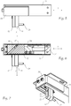
- Fig. 2 shows a cross section of the sliding door 1 in a sectional plane 8 according to the Fig. 1 , with only the uppermost part of the sliding door 1 being shown. It can be seen that a movable leaf in the form of a door leaf 20 is mounted in a door frame 30. Covers 3, 4 of the frame profiles of door 1 can be seen.
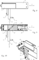
- FIG. 3 and 4 represent a main part 31 of the locking mechanism of the sliding door construction according to the Fig. 1 represents which can be integrated in the door frame 30.
- the main part 31 is arranged in the assembled state of the device in the door frame 30 of the door 1.
- a drive means 50 serves to move a sliding body 40 in a first direction 5 within the main part 31.
- the drive means 50 comprises a housing 51 with a linear drive in the form of a geared motor 52 and a push rod or a spindle 53.
- a push body 40 is fastened to the push rod.
- Sensor elements can be assigned to the drive means 50, each of which detects an end position of the movement of the sliding body 40 along the first direction 5.
- the sensor elements are preferably designed as reed switches.
- the individual components can be connected to each other using various screws or nuts, as in Fig. 4 indicated.
- the sliding body 40 comprises two side parts 43, 44, each of which has a groove 41 and 42, preferably on the side facing inwards.
- the side parts 43, 44 are connected via a nut 54, the nut 54 being provided to receive one end of the spindle 53.
- the sliding body 40 is U-shaped and also has cover plates 56 and 57 and an end cover 58.
- the main part 31 further comprises a holder 59 for fastening in the door frame 30.
- the main part 31 has a lifting body 33 protruding from the main part 31, which is movably mounted in the main part 31 along a lifting direction 7 running transverse to the first direction 5.
- the locking device also has a lifting body 33 which projects downward from the main part 31 and serves to actuate the device.
- the lifting body 33 has an actuating element 34 projecting transversely to the lifting direction 7 in the form of a bolt.
- the bolt serves as a locking bolt, which is set up to engage in a locking device 21 of the door leaf 20 when the door leaf 20 ( Fig. 11 and 12th ) is brought into a closing position in the door frame 30 in order to lock the closing device 21 by a movement along the lifting direction 7.
- the sliding body 40 and the lifting body 33 are coupled to one another via a groove guide, which converts a movement of the sliding body 40 in the first direction 5 into a lifting movement of the lifting body 33 along the lifting direction 7.
- An optional guide block 55 is arranged between the nut 54 and the lifting body 33.
- the groove guide includes a groove 41, 42, preferably a straight groove, which runs obliquely to the first direction 5 and the stroke direction 7, and a sliding element 35 arranged therein.
- the lifting body 33 has, as a sliding element 35, two pins located opposite one another, each in one of the grooves 41, 42 intervene.
- the pins are designed as ends of a pin running through the lifting body 33 as a sliding element 35.
- the sliding body 40 has two side parts 43, 44 arranged on both sides of the lifting body 33, in each of which a groove 41, 42, preferably a straight groove, extending obliquely to the first direction 5 and the lifting direction 7 is formed.
- a guide body 32 Adjacent to the lifting body 33, a guide body 32 is arranged in parallel, which is attached to the main part 31 and fixed there.
- the guide body 32 has an elongated closing guide 37 with a longitudinal extent, into which a on the lifting body 33 attached stroke guide element 36 engages and the lifting body 33 is movable along the longitudinal extent of the closing guide 37 in the stroke direction 7.
- the elongated closing guide 37 forms a groove in which the stroke guide element 36, for example a cylinder with a mushroom-shaped end, can slide in the stroke direction 7 during a stroke movement.
- the length of the locking guide 37 limits the actuation path of the locking device 21.
- the actuating element 34 is arranged so as to protrude into a corresponding opening of the closing device 21 in the door.
- the actuating element 34 only engages in the closing device 21 of the door leaf 20 when the door leaf 20 is in the closed position.
- a first group of components such as the guide body 32, the side parts 43, 44 with the grooves 41 and 42 and the guide block 55, can be made of brass or anodized aluminum.
- a second group of components such as the lifting body 33, the actuating element 34 and the sliding element 35, can be made of stainless steel.
- the first group of components is made of a softer material than the second group of components because of the desired higher mechanical strength.
- FIG. 5 to 7 show the device with respect to the position of the lifting body 33 or the actuating element 34 in an unlocked state, which corresponds to a first end of the intended course of the linear movement.
- the lifting body 33 is in a position in which the outer edges of the lifting body 33 coincide with those of the adjacent guide body 32.
- the lifting body 33 is thus in a "retracted” state in the lifting direction 7.
- a rotary movement generated by the geared motor 52 is transmitted to the nut 54 by means of the spindle 53 and converted into a linear movement in the first direction 5 of the sliding body 40.
- Fig. 6 the sliding element 35 can be seen, which is located at the upper end of the groove 41. It can also be seen that the lifting body 33 is "retracted” to open the doors 1, 2.
- the linear movement causes the sliding element 35, which is mounted in the two grooves 41, 42, to move in the lifting direction 7.
- the lifting body 33 can be raised or lowered.
- the movement of the lifting body 33 is limited by the dimension and size of the closing guide 37, since the lifting guide element 36 attached to the lifting body 33 engages in the closing guide 37 and guides the lifting body 33 in the intended movement path, which is defined by the closing guide 37.
- the end position of the linear movement can be monitored by sensors, for example inductive or mechanical switches, but also optical sensors, as is known to the person skilled in the art.
- the geared motor 52 can be controlled by means of a corresponding control, but this is not shown in the figures.
- Fig. 9 the sliding element 35 can be seen, which is located at the lower end of the groove 41. It can also be seen that the lifting body 33 is "extended” for a closing operation.
- Fig. 11 and 12th each show a view of the sliding door arrangement of the two sliding doors 1 and 2 in the unlocked and locked state.
- the actuating element 34 engages in the closing device 21 located on the door side by means of the lifting body 33.
- the locking device 21 of the door 1 locks both doors to one another via a locking plate 60 of the door 2.
Landscapes
- Engineering & Computer Science (AREA)
- Civil Engineering (AREA)
- Structural Engineering (AREA)
- Physics & Mathematics (AREA)
- Electromagnetism (AREA)
- Power-Operated Mechanisms For Wings (AREA)
Description
- Die Erfindung betrifft eine Vorrichtung zum Verriegeln eines in einem Türrahmen beweglichen Türblatts einer Tür, insbesondere Schiebetür.
- Die moderne Architektur möchte neben feststehenden Fenster-Lösungen für Eckwände und Hausecken auch auf Schiebetür-Lösungen zugreifen, wobei an der Ecke selbst kein Mauer- oder Tragelement vorgesehen sein soll. Mit anderen Worten, es soll die Ecke selbst als Fenster oder Tür ausgeführt sein.
- Ferner sollen Stulp-Anordnungen von Schiebetüren verfügbar sein, bei welchen zwei bewegliche Türflügel einer Schiebetüre in einer Ebene gegenläufig verschiebbar und die Türflügel "Stoß-an-Stoß" schließbar sind.
- Herkömmliche Schiebetüren sind häufig so konstruiert, dass sie zur Verriegelung in einem geschlossenen Zustand eine zweiteilige Schließvorrichtung vorsehen. Dabei ist ein Teil in einem beweglichen Türflügel untergebracht, der zweite Teil im Türrahmen, welcher mit Mauerwerk verbunden ist. Der im Rahmen untergebrachte Teil ist häufig groß und schwer. Der im Rahmen untergebrachte zweite Teil der Schiebetür ist daher häufig nicht dafür geeignet, wiederum in eine Schiebetür eingebaut zu werden.
-
EP 2 871 313 A1 betrifft eine Verriegelungsvorrichtung für ein, insbesondere mehrere einzeln verschiebbare Flügel umfassendes, Schiebewand- oder Schiebetürsystem, wobei die Verriegelungsvorrichtung einen zur Befestigung an einem verschiebbaren Flügel ausgebildeten Grundkörper, ein in einer Schließrichtung aus dem Grundkörper ausfahrbares Riegelelement, einen quer zu der Schließrichtung zu beaufschlagenden Stößel und eine Umlenkeinrichtung umfasst, welche bei einer Beaufschlagung des Stößels quer zur der Schließrichtung eine Ausfahrbewegung des Riegelelements mit einer Bewegungskomponente in der Schließrichtung herbeiführt. -
EP 1 775 402 A2 betrifft eine Vorrichtung zum An- und Abkuppeln zwischen einen Schiebeflügel und einen Ständer. -
DE 102011089121 B3 betrifft eine Verriegelungsvorrichtung für eine Schiebetür, mit einem Schiebeflügel, der mit mindestens einem Rollenwagen in einer ortsfesten Führungsschiene verschiebbar geführt ist, wobei die Verriegelungsvorrichtung mittels eines Aktors betätigbar ist. - Es ist Aufgabe der Erfindung die genannten Nachteile zu überwinden und eine Schiebetür-Anordnung zu schaffen, welche beispielsweise für eine Eck-Anordnung in einem Haus geeignet ist, leicht ist und eine schlanke Bauform aufweist.
- Die Aufgabe wird durch eine Vorrichtung der eingangs genannten Art gelöst, wobei die Vorrichtung umfasst:
- einen Hauptteil, welcher im montierten Zustand der Vorrichtung im Türrahmen der Tür angeordnet ist, einen Schiebekörper und ein Antriebsmittel zum Bewegen des Schiebekörpers in einer ersten Richtung innerhalb des Hauptteils aufweist, und
- einen aus dem Hauptteil herausragenden Hubkörper, welcher in dem Hauptteil längs einer quer zur ersten Richtung verlaufenden Hubrichtung beweglich gelagert ist, wobei der Hubkörper ein quer zu der Hubrichtung vorspringendes Betätigungselement aufweist, welches dazu eingerichtet ist, in eine Schließvorrichtung des Türblatts einzugreifen, wenn das Türblatt in eine schließende Stellung im Türrahmen gebracht wird, und die Schließvorrichtung durch eine Bewegung entlang der Hubrichtung zu verriegeln,
- Dadurch wird eine Vorrichtung geschaffen, die eine Schließvorrichtung beispielsweise von oben betätigen kann. Die Schließvorrichtung kann somit zwischen zwei beweglichen Türblättern angeordnet werden.
- In einer Weiterbildung der Erfindung beinhaltet die Nutführung eine schräg zu der ersten Richtung und der Hubrichtung verlaufende Nut, vorzugsweise gerade Nut, und ein darin angeordnetes Gleitelement. Dadurch wird auf einfache Weise eine Umsetzung einer Horizontalbewegung in eine Vertikalbewegung erreicht,
- Es ist günstig, wenn der Schiebekörper zwei beiderseits des Hubkörpers angeordnete Seitenteile aufweist, in denen je eine schräg zu der ersten Richtung und der Hubrichtung verlaufende Nut, vorzugsweise gerade Nut, ausgebildet ist, und der Hubkörper als Gleitelement zwei einander gegenüberliegende Zapfen aufweist, welche in jeweils eine der Nuten eingreifen. Dies ermöglicht eine symmetrische Anordnung der Komponenten, die unerwünschte Drehmomente bei seitlichen Verbindungen vermeidet.
- Es ergibt eine einfache Konstruktion und Montage, wenn die Zapfen als Enden eines durch den Hubkörper verlaufenden Stiftes als Gleitelement ausgebildet sind.
- Eine zuverlässige Definition der Hubbewegung lässt sich beispielweise erreichen, wenn angrenzend zum Hubkörper ein Führungskörper angeordnet ist, welcher am Hauptteil angebracht ist und eine längliche Schließführung mit einer Längserstreckung aufweist, in welche ein an dem Hubkörper angebrachtes Hubführungselement eingreift und der Hubkörper längs der Längserstreckung der Schließführung in der Hubrichtung beweglich ist.
- In einer Weiterbildung der Erfindung ist im montierten Zustand der Vorrichtung das Betätigungselement in eine Öffnung der Schließvorrichtung in der Tür hineinragend angeordnet. Das Betätigungselement greift erst in der schließenden Stellung des Türblatts in die Schließvorrichtung des Türblatts ein.
- Es lässt sich eine einfache und platzsparende Lösung erreichen, wenn das Antriebsmittel einen Linearantrieb für eine Schubstange umfasst, an der der Schiebekörper befestigt ist.
- Es lässt sich eine einfache Überwachung der Endpositionen des Hubkörpers über die Position des Antriebs ermitteln, wenn dem Antriebsmittel zugeordnete Sensorelemente, welche jeweils eine Endstellung der Bewegung des Schiebekörpers entlang der ersten Richtung erfassen, wobei die Sensorelemente vorzugsweise als Reedschalter ausgebildet sind.
- Die Aufgabe wird ferner durch eine eingangs genannte Tür, insbesondere Schiebetür, mit einem in einem Türrahmen beweglichen Türblatt mit einer Schließvorrichtung gelöst, mit der das Türblatt in einer geschlossenen Stellung des Türblatts verriegelbar ist, und mit einer in dem Türrahmen angeordneten erfindungsgemäßen Vorrichtung.
- Das Antriebsmittel dient zur Verschiebung des Schiebekörpers, d.h. zur Betätigung der Verriegelungs-Vorrichtung. Es ist nicht zu verwechseln mit einem möglicherweise zusätzlich vorgesehenen Motor zum Verschieben des Türblatts, d.h. zum Schließen bzw. Freigeben des Durchgangs, der durch die Schiebetür verschlossen werden kann.
- Es ist dem Fachmann bekannt, dass das Antriebsmittel in Form eines Linearmotors zusätzlich eine elektrische Ansteuerung erfordert, auf die jedoch nicht weiter eingegangen wird.
- Die Erfindung und weitere Vorteile werden im Folgenden anhand eines nicht einschränkenden Ausführungsbeispiels näher beschrieben, welches in den beiliegenden Zeichnungen veranschaulicht ist. Die Zeichnungen zeigen in
- Fig. 1
- eine Schnittansicht von oben auf ein Ausführungsbeispiel der Erfindung mit zwei im rechten Winkel zueinander angeordneten Schiebetüren,
- Fig. 2
- eine Querschnittsansicht durch einen Türrahmen gemäß dem Ausführungsbeispiel der
Fig. 1 , - Fig. 3
- eine perspektivische Ansicht auf einen Hauptteil einer Verriegelungs-Vorrichtung gemäß dem Ausführungsbeispiel der
Fig. 1 , - Fig. 4
- eine Explosionsansicht des Hauptteils der
Fig. 3 , - Fig. 5
- eine Seitenansicht auf den Hauptteil der
Fig. 3 in einem entriegelten Zustand, - Fig. 6
- eine Schnittansicht des Hauptteils der
Fig. 5 , - Fig. 7
- eine perspektivische Ansicht auf den Hauptteil der
Fig. 5 , - Fig. 8
- eine Seitenansicht auf den Hauptteil der
Fig. 3 in einem verriegelten Zustand, - Fig. 9
- eine Schnittansicht gemäß der
Fig. 8 , - Fig. 10
- eine perspektivische Ansicht auf den Hauptteil der
Fig. 8 , - Fig. 11
- eine Seitenansicht auf die Anordnung gemäß der
Fig. 1 im entriegelten Zustand, - Fig. 12
- eine Seitenansicht auf die Anordnung gemäß der
Fig. 1 im verriegelten Zustand, - Unter Bezugnahme auf
Fig. 1 bis Fig. 12 wird nun ein Ausführungsbeispiel der Erfindung näher erläutert. Insbesondere sind für die Erfindung in einer Schiebetür wichtige Teile dargestellt, wobei klar ist, dass eine Schiebetüre noch viele andere, nicht gezeigte Teile enthält. Der Übersichtlichkeit halber sind daher beispielsweise Rollen, Rollenführungen, Federungen, Sensoren oder Ansteuerungselektronik nicht gezeigt. -
Fig. 1 zeigt eine Schiebetürenanordnung mit zwei Schiebetüren 1, 2 gemäß der Erfindung, welche in Form einer Eckanordnung zueinander beispielsweise einen rechten Winkel aufweisen. Die Schiebetüren können entlang der Richtungen 5 bzw. 6 beidseitig verschoben werden. Sind beide Schiebetüren geöffnet, so weist der freigegebene Eckbereich keinerlei Konstruktionselemente auf, an welchen Schließeinrichtungen angebracht sind. Die zur Verriegelung vorgesehenen Schließeinrichtungen sind in den Endkanten der beweglichen Türflügel der beiden Schiebetüren 1, 2 angebracht. - Eine alternative, nicht gesondert dargestellte Ausführungsform kann eine Stulp-Anordnung zweier, zueinander gegenläufiger beweglicher Türflügel sein, welche auf demselben Verriegelungs-Prinzip der in
Fig. 1 gezeigten Schiebetürenanordnung basiert. -
Fig. 2 zeigt einen Querschnitt der Schiebetür 1 in einer Schnittebene 8 gemäß derFig. 1 , wobei nur der oberste Teil der Schiebetür 1 dargestellt ist. Es ist erkennbar, dass ein beweglicher Flügel in Form eines Türblatts 20 in einem Türrahmen 30 gelagert ist. Es sind Abdeckungen 3, 4 der Rahmenprofile der Tür 1 erkennbar. -
Fig. 3 und 4 stellen einen Hauptteil 31 der Verriegelungsmechanik der Schiebetürenkonstruktion gemäß derFig. 1 dar, welcher im Türrahmen 30 integrierbar ist. - Der Hauptteil 31 ist im montierten Zustand der Vorrichtung im Türrahmen 30 der Tür 1 angeordnet. Ein Antriebsmittel 50 dient zum Bewegen eines Schiebekörpers 40 in einer ersten Richtung 5 innerhalb des Hauptteils 31.
- Das Antriebsmittel 50 umfasst in diesem Beispiel ein Gehäuse 51 mit einem Linearantrieb in Form eines Getriebemotors 52 und einer Schubstange bzw. einer Spindel 53. An der Schubstange ist ein Schiebekörper 40 befestigt.
- Dem Antriebsmittel 50 können Sensorelemente zugeordnet sein, welche jeweils eine Endstellung der Bewegung des Schiebekörpers 40 entlang der ersten Richtung 5 erfassen. Die Sensorelemente sind vorzugsweise als Reedschalter ausgebildet.
- Die einzelnen Komponenten können mittels diverser Schrauben bzw. Muttern miteinander verbunden werden, wie in
Fig. 4 angedeutet. - Der Schiebekörper 40 umfasst in diesem Beispiel zwei Seitenteile 43, 44, welche jeweils eine, vorzugsweise auf der nach innen zugewandten Seite, Nut 41 und 42 aufweisen. Die Seitenteile 43, 44 sind über eine Mutter 54 verbunden, wobei die Mutter 54 dazu vorgesehen ist, ein Ende der Spindel 53 aufzunehmen. Zusammengesetzt ist der Schiebekörper 40 U-förmig geformt und weist ferner Abdeckplatten 56 und 57 sowie einen Enddeckel 58 auf.
- Der Hauptteil 31 umfasst ferner eine Halterung 59 zur Befestigung in dem Türrahmen 30.
- Außerdem weist der Hauptteil 31 einen aus dem Hauptteil 31 herausragenden Hubkörper 33 auf, welcher in dem Hauptteil 31 längs einer quer zur ersten Richtung 5 verlaufenden Hubrichtung 7 beweglich gelagert ist.
- Die Verriegelungs-Vorrichtung weist ferner einen Hubkörper 33 auf, der nach unten aus dem Hauptteil 31 ragt und dem Betätigen der Vorrichtung dient.
- Der Hubkörper 33 weist ein quer zu der Hubrichtung 7 vorspringendes Betätigungselement 34 in Form eines Bolzens auf. Der Bolzen dient als Schließbolzen, der dazu eingerichtet ist, in eine Schließvorrichtung 21 des Türblatts 20 einzugreifen, wenn das Türblatt 20 (
Fig. 11 und12 ) in eine schließende Stellung im Türrahmen 30 gebracht wird, um die Schließvorrichtung 21 durch eine Bewegung entlang der Hubrichtung 7 zu verriegeln. - Der Schiebekörper 40 und der Hubkörper 33 sind über eine Nutführung miteinander gekoppelt, welche eine Bewegung des Schiebekörpers 40 in der ersten Richtung 5 in eine Hubbewegung des Hubkörpers 33 entlang der Hubrichtung 7 umsetzt. Ein optionaler Führungsblock 55 ist zwischen der Mutter 54 und dem Hubkörper 33 angeordnet.
- Die Nutführung beinhaltet eine schräg zu der ersten Richtung 5 und der Hubrichtung 7 verlaufende Nut 41, 42, vorzugsweise gerade Nut, und ein darin angeordnetes Gleitelement 35. Der Hubkörper 33 weist als Gleitelement 35 zwei einander gegenüberliegende Zapfen auf, welche in jeweils eine der Nuten 41, 42 eingreifen. In diesem Beispiel sind die Zapfen als Enden eines durch den Hubkörper 33 verlaufenden Stiftes als Gleitelement 35 ausgebildet.
- Der Schiebekörper 40 weist zwei beiderseits des Hubkörpers 33 angeordnete Seitenteile 43, 44 auf, in denen je eine schräg zu der ersten Richtung 5 und der Hubrichtung 7 verlaufende Nut 41, 42, vorzugsweise gerade Nut, ausgebildet ist.
- Angrenzend zum Hubkörper 33 ist parallel ein Führungskörper 32 angeordnet, welcher am Hauptteil 31 angebracht und dort fixiert ist. Der Führungskörper 32 weist eine längliche Schließführung 37 mit einer Längserstreckung auf, in welche ein an dem Hubkörper 33 angebrachtes Hubführungselement 36 eingreift und der Hubkörper 33 längs der Längserstreckung der Schließführung 37 in der Hubrichtung 7 beweglich ist.
- Die längliche Schließführung 37 bildet eine Nut, in welcher das Hubführungselement 36, beispielsweise ein Zylinder mit pilzförmigem Ende, bei einer Hubbewegung in der Hubrichtung 7 gleiten kann. Die Länge der Schließführung 37 begrenzt den Betätigungsweg der Schließvorrichtung 21.
- Im montierten Zustand der Vorrichtung ist das Betätigungselement 34 in eine korrespondierende Öffnung der Schließvorrichtung 21 in der Tür hineinragend angeordnet.
- Das Betätigungselement 34 greift erst in der schließenden Stellung des Türblatts 20 in die Schließvorrichtung 21 des Türblatts 20 ein.
- Für eine gute Gleitfähigkeit der beweglichen Komponenten kann beispielsweise eine erste Gruppe von Komponenten, wie der Führungskörper 32, die Seitenteile 43, 44 mit den Nuten 41 und 42 sowie der Führungsblock 55, aus Messing oder eloxiertem Aluminium gefertigt sein. Eine zweite Gruppe von Komponenten, wie der Hubkörper 33, das Betätigungselement 34 sowie das Gleitelement 35, kann aus Edelstahl gefertigt sein.
- Es ist besonders günstig, wenn die erste Gruppe von Komponenten wegen der gewünschten höheren mechanischen Festigkeit aus einem weicheren Material als die zweite Gruppe von Komponenten hergestellt ist.
-
Fig. 5 bis 7 zeigen die Vorrichtung hinsichtlich der Lage des Hubkörpers 33 bzw. des Betätigungselements 34 in einem entriegelten Zustand, welcher einem ersten Ende des vorgesehenen Verlaufs der Linearbewegung entspricht. Der Hubkörper 33 befindet sich in einer Position, in welcher sich die Außenkanten des Hubkörpers 33 mit jenen des benachbart angeordneten Führungskörpers 32 decken. Der Hubkörper 33 ist somit in einem, in Hubrichtung 7 "eingefahrenen" Zustand. - Eine durch den Getriebemotor 52 erzeugte Drehbewegung wird mittels der Spindel 53 an die Mutter 54 übertragen und in eine Linearbewegung in die ersten Richtung 5 des Schiebekörpers 40 konvertiert.
- In
Fig. 6 ist das Gleitelement 35 erkennbar, welches sich am oberen Ende der Nut 41 befindet. Ferner ist erkennbar, dass der Hubkörper 33 zum Öffnen der Tür 1, 2 "eingefahren" ist. - Die Linearbewegung veranlasst das Gleitelement 35, welches in den beiden Nuten 41, 42 gelagert ist, zu einer Bewegung in der Hubrichtung 7. Dadurch kann der Hubkörper 33 angehoben oder abgesenkt werden. Die Bewegung des Hubkörpers 33 ist dabei durch die Dimension und Größe der Schließführung 37 begrenzt, da das am Hubkörper 33 angebrachte Hubführungselement 36 in die Schließführung 37 eingreift und den Hubkörper 33 in der vorgesehenen Bewegungsbahn, welche durch die Schließführung 37 definiert ist, führt.
- Eine Überwachung der Endposition der Linearbewegung kann durch Sensoren erfolgen, beispielsweise induktive oder mechanische Schalter, aber auch optische Sensoren, wie dem Fachmann bekannt.
- Der Getriebemotor 52 kann über eine entsprechende Steuerung angesteuert werden, was jedoch in den Figuren nicht dargestellt ist.
-
Fig. 8 bis 10 zeigen die Vorrichtung hinsichtlich der Lage des Hubkörpers 33 bzw. des Betätigungselements 34 in einem verriegelten Zustand, welcher einem zweiten Ende des vorgesehenen Verlaufs der Linearbewegung entspricht. Das erste Ende und das zweite Ende begrenzen die vorgesehene Bewegungsbahn der Linearbewegung. - In
Fig. 9 ist das Gleitelement 35 erkennbar, welches sich am unteren Ende der Nut 41 befindet. Ferner ist erkennbar, dass der Hubkörper 33 für einen Schließvorgang "ausgefahren" ist. -
Fig. 11 und12 zeigen jeweils eine Ansicht auf die Schiebetürenanordnung der zwei Schiebetüren 1 und 2 im entriegelten und verriegelten Zustand. Das Betätigungselement 34 greift mittels des Hubkörpers 33 in die türseitig gelegene Schließvorrichtung 21 ein. Die Schließvorrichtung 21 der Tür 1 versperrt über ein Schließblech 60 der Tür 2 beide Türen gegenseitig. - Liste der Bezugszeichen:
- 1, 2
- Tür
- 3, 4
- Abdeckungen der Rahmenprofile der Tür
- 5, 6, 7
- Richtung
- 8
- Schnittebene
- 20
- Türblatt
- 21
- Schließvorrichtung
- 30
- Türrahmen
- 31
- Hauptteil
- 32
- Führungskörper
- 33
- Hubkörper
- 34
- Betätigungselement, Schließbolzen
- 35
- Gleitelement, Zapfen, Stift
- 36
- Hubführungselement
- 37
- Schließführung
- 40
- Schiebekörper
- 41, 42
- Nut
- 43, 44
- Seitenteil
- 50
- Antriebsmittel
- 51
- Gehäuse
- 52
- Getriebemotor
- 53
- Schubstange, Spindel
- 54
- Mutter
- 55
- Führungsblock
- 56, 57
- Abdeckplatte
- 58
- Enddeckel
- 59
- Halterung
- 60
- Schließblech, Haken
Claims (9)
- Vorrichtung zum Verriegeln eines in einem Türrahmen (30) beweglichen Türblatts (20) einer Tür (1, 2), insbesondere Schiebetür, welche Vorrichtung umfasst:- einen Hauptteil (31), welcher im montierten Zustand der Vorrichtung im Türrahmen (30) der Tür (1, 2) angeordnet ist, einen Schiebekörper (40) und ein Antriebsmittel (50) zum Bewegen des Schiebekörpers (40) in einer ersten Richtung (5, 6) innerhalb des Hauptteils (31) aufweist, und- einen aus dem Hauptteil (31) herausragenden Hubkörper (33), welcher in dem Hauptteil (31) längs einer quer zur ersten Richtung (5, 6) verlaufenden Hubrichtung (7) beweglich gelagert ist, wobei der Hubkörper (33) ein quer zu der Hubrichtung (7) vorspringendes Betätigungselement (34) aufweist, welches dazu eingerichtet ist, in eine Schließvorrichtung (21) des Türblatts (20) einzugreifen, wenn das Türblatt (20) in eine schließende Stellung im Türrahmen (30) gebracht wird, und die Schließvorrichtung (21) durch eine Bewegung entlang der Hubrichtung (7) zu verriegeln,wobei der Schiebekörper (40) und der Hubkörper (33) über eine Nutführung miteinander gekoppelt sind, welche eine Bewegung des Schiebekörpers (40) in der ersten Richtung (5, 6) in eine Hubbewegung des Hubkörpers (33) entlang der Hubrichtung (7) umsetzt.
- Vorrichtung nach Anspruch 1, dadurch gekennzeichnet, dass die Nutführung eine schräg zu der ersten Richtung (5, 6) und der Hubrichtung (7) verlaufende Nut (41, 42), vorzugsweise gerade Nut, und ein darin angeordnetes Gleitelement (35) beinhaltet.
- Vorrichtung nach Anspruch 2, dadurch gekennzeichnet, dass der Schiebekörper (40) zwei beiderseits des Hubkörpers (33) angeordnete Seitenteile (43, 44) aufweist, in denen je eine schräg zu der ersten Richtung (5, 6) und der Hubrichtung (7) verlaufende Nut (41, 42), vorzugsweise gerade Nut, ausgebildet ist, und der Hubkörper (33) als Gleitelement (35) zwei einander gegenüberliegende Zapfen aufweist, welche in jeweils eine der Nuten (41, 42) eingreifen.
- Vorrichtung nach Anspruch 3, dadurch gekennzeichnet, dass die Zapfen als Enden eines durch den Hubkörper (33) verlaufenden Stiftes als Gleitelement (35) ausgebildet sind.
- Vorrichtung nach einem der vorhergehenden Ansprüche, dadurch gekennzeichnet, dass angrenzend zum Hubkörper (33) ein Führungskörper (32) angeordnet ist, welcher am Hauptteil (31) angebracht ist und eine längliche Schließführung (37) mit einer Längserstreckung aufweist, in welche ein an dem Hubkörper (33) angebrachtes Hubführungselement (36) eingreift und der Hubkörper (33) längs der Längserstreckung der Schließführung (37) in der Hubrichtung (7) beweglich ist.
- Vorrichtung nach einem der vorhergehenden Ansprüche, dadurch gekennzeichnet, dass im montierten Zustand der Vorrichtung das Betätigungselement (34) in eine Öffnung der Schließvorrichtung (21) in der Tür hineinragend angeordnet ist und erst in der schließenden Stellung des Türblatts (20) in die Schließvorrichtung (21) des Türblatts (20) eingreift.
- Vorrichtung nach einem der vorhergehenden Ansprüche, dadurch gekennzeichnet, dass das Antriebsmittel (50) einen Linearantrieb für eine Schubstange umfasst, an der der Schiebekörper (40) befestigt ist.
- Vorrichtung nach einem der vorhergehenden Ansprüche, gekennzeichnet durch dem Antriebsmittel (50) zugeordnete Sensorelemente, welche jeweils eine Endstellung der Bewegung des Schiebekörpers (40) entlang der ersten Richtung (5, 6) erfassen, wobei die Sensorelement vorzugsweise als Reedschalter ausgebildet sind.
- Tür (1, 2), insbesondere Schiebetür, mit einem in einem Türrahmen (30) beweglichen Türblatt (20) mit einer Schließvorrichtung (21), mit der das Türblatt (20) in einer geschlossenen Stellung des Türblatts (20) verriegelbar ist, und mit einer in dem Türrahmen (30) angeordneten Vorrichtung nach einem der vorhergehenden Ansprüche.
Applications Claiming Priority (1)
| Application Number | Priority Date | Filing Date | Title |
|---|---|---|---|
| ATA51036/2017A AT520645B1 (de) | 2017-12-15 | 2017-12-15 | Verriegelungsvorrichtung für eine Tür, insbesondere Schiebetür |
Publications (2)
| Publication Number | Publication Date |
|---|---|
| EP3498960A1 EP3498960A1 (de) | 2019-06-19 |
| EP3498960B1 true EP3498960B1 (de) | 2020-07-15 |
Family
ID=64664975
Family Applications (1)
| Application Number | Title | Priority Date | Filing Date |
|---|---|---|---|
| EP18211849.7A Active EP3498960B1 (de) | 2017-12-15 | 2018-12-12 | Verriegelungsvorrichtung für eine tür, insbesondere schiebetür |
Country Status (2)
| Country | Link |
|---|---|
| EP (1) | EP3498960B1 (de) |
| AT (1) | AT520645B1 (de) |
Families Citing this family (3)
| Publication number | Priority date | Publication date | Assignee | Title |
|---|---|---|---|---|
| CN111335733B (zh) * | 2020-04-23 | 2023-08-01 | 魏超明 | 一种手动开关装置及平移门 |
| CN113775614B (zh) * | 2021-09-14 | 2023-03-03 | 海安奥克机械制造有限公司 | 一种防盗效果好的升降器材用锁紧装置 |
| DE102023202379A1 (de) | 2023-03-16 | 2024-09-19 | Roto Frank Fenster- und Türtechnologie GmbH | Eckfenster oder Ecktür mit abstellbaren und parallel zum festen Rahmen verschiebbaren Schiebeflügeln |
Family Cites Families (3)
| Publication number | Priority date | Publication date | Assignee | Title |
|---|---|---|---|---|
| FR2891296B1 (fr) * | 2005-09-26 | 2007-12-28 | Norsk Hydro As | Dispositif d'accrochage et de decrochage entre un coulissant et un montant. |
| DE102011089121B3 (de) * | 2011-12-20 | 2013-01-31 | Geze Gmbh | Verriegelungsvorrichtung für eine Schiebetür |
| DE102013222581A1 (de) * | 2013-11-07 | 2015-05-07 | Geze Gmbh | Verriegelungsvorrichtung |
-
2017
- 2017-12-15 AT ATA51036/2017A patent/AT520645B1/de not_active IP Right Cessation
-
2018
- 2018-12-12 EP EP18211849.7A patent/EP3498960B1/de active Active
Non-Patent Citations (1)
| Title |
|---|
| None * |
Also Published As
| Publication number | Publication date |
|---|---|
| AT520645B1 (de) | 2019-06-15 |
| EP3498960A1 (de) | 2019-06-19 |
| AT520645A4 (de) | 2019-06-15 |
Similar Documents
| Publication | Publication Date | Title |
|---|---|---|
| EP2166180B1 (de) | Schliessanlage | |
| EP2476829B1 (de) | Hebe-Schiebe-Konstruktion, insbesondere Hebe-Schiebe-Tür oder Hebe-Schiebe-Fenster | |
| DE19912717A1 (de) | Fenster oder Tür | |
| EP3102759B1 (de) | Beschlag eines zumindest hebbaren und verschiebbaren flügels von fenstern oder türen | |
| EP1816292B1 (de) | Verschluss für einen Treibstangenbeschlag | |
| EP2682545B1 (de) | Verschlussanordnung für eine Schiebetür oder ein Schiebefenster, und Schiebetür oder Schiebefenster | |
| EP3498960B1 (de) | Verriegelungsvorrichtung für eine tür, insbesondere schiebetür | |
| DE202022100517U1 (de) | Profilanordnung eines Fensters oder einer Tür mit einem Flügelprofil, insbesondere einem Schiebeflügelprofil | |
| EP3620602A1 (de) | Vorrichtung zum öffnen und/oder schliessen, sowie zum verriegeln eines geschlossenen zustandes einer verschlusseinrichtung, zum verschliessen einer raumöffnung, sowie eine verschlusseinrichtung mit einer solchen vorrichtung | |
| EP3859107B1 (de) | Schiebetür | |
| EP3060737B1 (de) | Fenster oder tür mit einem beschlag | |
| EP0152791B1 (de) | Stellvorrichtung für Schiebeflügel von Fenstern, Türen od. dgl. | |
| EP2146032A1 (de) | Vorrichtung zum Öffnen und/oder Schliessen sowie zum Verriegeln eines geschlossenen Zustandes einer Verschlusseinrichtung zum Verschliessen einer Raumöffnung sowie Verschlusseinrichtung mit einer solchen Vorrichtung | |
| DE202022100516U1 (de) | Verlagerungsvorrichtung zur zwangsweisen Verlagerung eines Flügels, insbesondere eines Schiebeflügels, eines Fensters oder einer Tür | |
| EP2520746A1 (de) | Elektrisch betätigbares Schloss | |
| DE202022100514U1 (de) | Verlagerungsvorrichtung zur zwangsweisen Verlagerung eines Flügels, insbesondere eines Schiebeflügels, eines Fensters oder einer Tür | |
| EP2871312A1 (de) | Spaltlüftungsanordnung für eine Schiebetür oder -fenster und Schiebetür oder -fenster | |
| DE19900875C2 (de) | Verriegelungsvorrichtung für eine Türanlage | |
| EP3159466A1 (de) | Verriegelungsvorrichtung mit zwei beweglichen verriegelungskörpern | |
| EP1573157B1 (de) | Schiebetürvorrichtung und Verfahren zum Verschliessen von Schiebetüren | |
| DE29923398U1 (de) | Schließsystem für Möbel | |
| EP3327237B1 (de) | Elektrischer zahnriemenantrieb für linearschiebetüren | |
| EP3362627B1 (de) | Spindelantrieb mit integrierter verriegelung | |
| EP4041974B1 (de) | Ausstellvorrichtung für einen dreh-kipp-flügel eines fensters oder einer tür | |
| EP4421285B1 (de) | Schiebetür mit einem verriegelbaren schiebeflügel |
Legal Events
| Date | Code | Title | Description |
|---|---|---|---|
| PUAI | Public reference made under article 153(3) epc to a published international application that has entered the european phase |
Free format text: ORIGINAL CODE: 0009012 |
|
| STAA | Information on the status of an ep patent application or granted ep patent |
Free format text: STATUS: THE APPLICATION HAS BEEN PUBLISHED |
|
| AK | Designated contracting states |
Kind code of ref document: A1 Designated state(s): AL AT BE BG CH CY CZ DE DK EE ES FI FR GB GR HR HU IE IS IT LI LT LU LV MC MK MT NL NO PL PT RO RS SE SI SK SM TR |
|
| AX | Request for extension of the european patent |
Extension state: BA ME |
|
| STAA | Information on the status of an ep patent application or granted ep patent |
Free format text: STATUS: REQUEST FOR EXAMINATION WAS MADE |
|
| 17P | Request for examination filed |
Effective date: 20191203 |
|
| RBV | Designated contracting states (corrected) |
Designated state(s): AL AT BE BG CH CY CZ DE DK EE ES FI FR GB GR HR HU IE IS IT LI LT LU LV MC MK MT NL NO PL PT RO RS SE SI SK SM TR |
|
| GRAP | Despatch of communication of intention to grant a patent |
Free format text: ORIGINAL CODE: EPIDOSNIGR1 |
|
| STAA | Information on the status of an ep patent application or granted ep patent |
Free format text: STATUS: GRANT OF PATENT IS INTENDED |
|
| INTG | Intention to grant announced |
Effective date: 20200205 |
|
| GRAS | Grant fee paid |
Free format text: ORIGINAL CODE: EPIDOSNIGR3 |
|
| GRAA | (expected) grant |
Free format text: ORIGINAL CODE: 0009210 |
|
| STAA | Information on the status of an ep patent application or granted ep patent |
Free format text: STATUS: THE PATENT HAS BEEN GRANTED |
|
| AK | Designated contracting states |
Kind code of ref document: B1 Designated state(s): AL AT BE BG CH CY CZ DE DK EE ES FI FR GB GR HR HU IE IS IT LI LT LU LV MC MK MT NL NO PL PT RO RS SE SI SK SM TR |
|
| RAP1 | Party data changed (applicant data changed or rights of an application transferred) |
Owner name: LIBERDA, VIKTOR Owner name: LIBERDA, RUDOLF |
|
| REG | Reference to a national code |
Ref country code: GB Ref legal event code: FG4D Free format text: NOT ENGLISH Ref country code: CH Ref legal event code: EP |
|
| REG | Reference to a national code |
Ref country code: IE Ref legal event code: FG4D Free format text: LANGUAGE OF EP DOCUMENT: GERMAN |
|
| REG | Reference to a national code |
Ref country code: DE Ref legal event code: R096 Ref document number: 502018001903 Country of ref document: DE |
|
| REG | Reference to a national code |
Ref country code: AT Ref legal event code: REF Ref document number: 1291224 Country of ref document: AT Kind code of ref document: T Effective date: 20200815 |
|
| REG | Reference to a national code |
Ref country code: LT Ref legal event code: MG4D |
|
| REG | Reference to a national code |
Ref country code: NL Ref legal event code: MP Effective date: 20200715 |
|
| PG25 | Lapsed in a contracting state [announced via postgrant information from national office to epo] |
Ref country code: GR Free format text: LAPSE BECAUSE OF FAILURE TO SUBMIT A TRANSLATION OF THE DESCRIPTION OR TO PAY THE FEE WITHIN THE PRESCRIBED TIME-LIMIT Effective date: 20201016 Ref country code: FI Free format text: LAPSE BECAUSE OF FAILURE TO SUBMIT A TRANSLATION OF THE DESCRIPTION OR TO PAY THE FEE WITHIN THE PRESCRIBED TIME-LIMIT Effective date: 20200715 Ref country code: NO Free format text: LAPSE BECAUSE OF FAILURE TO SUBMIT A TRANSLATION OF THE DESCRIPTION OR TO PAY THE FEE WITHIN THE PRESCRIBED TIME-LIMIT Effective date: 20201015 Ref country code: SE Free format text: LAPSE BECAUSE OF FAILURE TO SUBMIT A TRANSLATION OF THE DESCRIPTION OR TO PAY THE FEE WITHIN THE PRESCRIBED TIME-LIMIT Effective date: 20200715 Ref country code: ES Free format text: LAPSE BECAUSE OF FAILURE TO SUBMIT A TRANSLATION OF THE DESCRIPTION OR TO PAY THE FEE WITHIN THE PRESCRIBED TIME-LIMIT Effective date: 20200715 Ref country code: LT Free format text: LAPSE BECAUSE OF FAILURE TO SUBMIT A TRANSLATION OF THE DESCRIPTION OR TO PAY THE FEE WITHIN THE PRESCRIBED TIME-LIMIT Effective date: 20200715 Ref country code: BG Free format text: LAPSE BECAUSE OF FAILURE TO SUBMIT A TRANSLATION OF THE DESCRIPTION OR TO PAY THE FEE WITHIN THE PRESCRIBED TIME-LIMIT Effective date: 20201015 Ref country code: HR Free format text: LAPSE BECAUSE OF FAILURE TO SUBMIT A TRANSLATION OF THE DESCRIPTION OR TO PAY THE FEE WITHIN THE PRESCRIBED TIME-LIMIT Effective date: 20200715 Ref country code: PT Free format text: LAPSE BECAUSE OF FAILURE TO SUBMIT A TRANSLATION OF THE DESCRIPTION OR TO PAY THE FEE WITHIN THE PRESCRIBED TIME-LIMIT Effective date: 20201116 |
|
| PGFP | Annual fee paid to national office [announced via postgrant information from national office to epo] |
Ref country code: FR Payment date: 20201223 Year of fee payment: 3 |
|
| PG25 | Lapsed in a contracting state [announced via postgrant information from national office to epo] |
Ref country code: IS Free format text: LAPSE BECAUSE OF FAILURE TO SUBMIT A TRANSLATION OF THE DESCRIPTION OR TO PAY THE FEE WITHIN THE PRESCRIBED TIME-LIMIT Effective date: 20201115 Ref country code: PL Free format text: LAPSE BECAUSE OF FAILURE TO SUBMIT A TRANSLATION OF THE DESCRIPTION OR TO PAY THE FEE WITHIN THE PRESCRIBED TIME-LIMIT Effective date: 20200715 Ref country code: LV Free format text: LAPSE BECAUSE OF FAILURE TO SUBMIT A TRANSLATION OF THE DESCRIPTION OR TO PAY THE FEE WITHIN THE PRESCRIBED TIME-LIMIT Effective date: 20200715 Ref country code: RS Free format text: LAPSE BECAUSE OF FAILURE TO SUBMIT A TRANSLATION OF THE DESCRIPTION OR TO PAY THE FEE WITHIN THE PRESCRIBED TIME-LIMIT Effective date: 20200715 |
|
| PG25 | Lapsed in a contracting state [announced via postgrant information from national office to epo] |
Ref country code: NL Free format text: LAPSE BECAUSE OF FAILURE TO SUBMIT A TRANSLATION OF THE DESCRIPTION OR TO PAY THE FEE WITHIN THE PRESCRIBED TIME-LIMIT Effective date: 20200715 |
|
| REG | Reference to a national code |
Ref country code: DE Ref legal event code: R097 Ref document number: 502018001903 Country of ref document: DE |
|
| PG25 | Lapsed in a contracting state [announced via postgrant information from national office to epo] |
Ref country code: CZ Free format text: LAPSE BECAUSE OF FAILURE TO SUBMIT A TRANSLATION OF THE DESCRIPTION OR TO PAY THE FEE WITHIN THE PRESCRIBED TIME-LIMIT Effective date: 20200715 Ref country code: DK Free format text: LAPSE BECAUSE OF FAILURE TO SUBMIT A TRANSLATION OF THE DESCRIPTION OR TO PAY THE FEE WITHIN THE PRESCRIBED TIME-LIMIT Effective date: 20200715 Ref country code: RO Free format text: LAPSE BECAUSE OF FAILURE TO SUBMIT A TRANSLATION OF THE DESCRIPTION OR TO PAY THE FEE WITHIN THE PRESCRIBED TIME-LIMIT Effective date: 20200715 Ref country code: EE Free format text: LAPSE BECAUSE OF FAILURE TO SUBMIT A TRANSLATION OF THE DESCRIPTION OR TO PAY THE FEE WITHIN THE PRESCRIBED TIME-LIMIT Effective date: 20200715 Ref country code: IT Free format text: LAPSE BECAUSE OF FAILURE TO SUBMIT A TRANSLATION OF THE DESCRIPTION OR TO PAY THE FEE WITHIN THE PRESCRIBED TIME-LIMIT Effective date: 20200715 Ref country code: SM Free format text: LAPSE BECAUSE OF FAILURE TO SUBMIT A TRANSLATION OF THE DESCRIPTION OR TO PAY THE FEE WITHIN THE PRESCRIBED TIME-LIMIT Effective date: 20200715 |
|
| PLBE | No opposition filed within time limit |
Free format text: ORIGINAL CODE: 0009261 |
|
| STAA | Information on the status of an ep patent application or granted ep patent |
Free format text: STATUS: NO OPPOSITION FILED WITHIN TIME LIMIT |
|
| PG25 | Lapsed in a contracting state [announced via postgrant information from national office to epo] |
Ref country code: AL Free format text: LAPSE BECAUSE OF FAILURE TO SUBMIT A TRANSLATION OF THE DESCRIPTION OR TO PAY THE FEE WITHIN THE PRESCRIBED TIME-LIMIT Effective date: 20200715 |
|
| PGFP | Annual fee paid to national office [announced via postgrant information from national office to epo] |
Ref country code: DE Payment date: 20201221 Year of fee payment: 3 |
|
| 26N | No opposition filed |
Effective date: 20210416 |
|
| PG25 | Lapsed in a contracting state [announced via postgrant information from national office to epo] |
Ref country code: SK Free format text: LAPSE BECAUSE OF FAILURE TO SUBMIT A TRANSLATION OF THE DESCRIPTION OR TO PAY THE FEE WITHIN THE PRESCRIBED TIME-LIMIT Effective date: 20200715 |
|
| PG25 | Lapsed in a contracting state [announced via postgrant information from national office to epo] |
Ref country code: SI Free format text: LAPSE BECAUSE OF FAILURE TO SUBMIT A TRANSLATION OF THE DESCRIPTION OR TO PAY THE FEE WITHIN THE PRESCRIBED TIME-LIMIT Effective date: 20200715 Ref country code: MC Free format text: LAPSE BECAUSE OF FAILURE TO SUBMIT A TRANSLATION OF THE DESCRIPTION OR TO PAY THE FEE WITHIN THE PRESCRIBED TIME-LIMIT Effective date: 20200715 |
|
| REG | Reference to a national code |
Ref country code: BE Ref legal event code: MM Effective date: 20201231 |
|
| PG25 | Lapsed in a contracting state [announced via postgrant information from national office to epo] |
Ref country code: IE Free format text: LAPSE BECAUSE OF NON-PAYMENT OF DUE FEES Effective date: 20201212 Ref country code: LU Free format text: LAPSE BECAUSE OF NON-PAYMENT OF DUE FEES Effective date: 20201212 |
|
| PG25 | Lapsed in a contracting state [announced via postgrant information from national office to epo] |
Ref country code: TR Free format text: LAPSE BECAUSE OF FAILURE TO SUBMIT A TRANSLATION OF THE DESCRIPTION OR TO PAY THE FEE WITHIN THE PRESCRIBED TIME-LIMIT Effective date: 20200715 Ref country code: MT Free format text: LAPSE BECAUSE OF FAILURE TO SUBMIT A TRANSLATION OF THE DESCRIPTION OR TO PAY THE FEE WITHIN THE PRESCRIBED TIME-LIMIT Effective date: 20200715 Ref country code: CY Free format text: LAPSE BECAUSE OF FAILURE TO SUBMIT A TRANSLATION OF THE DESCRIPTION OR TO PAY THE FEE WITHIN THE PRESCRIBED TIME-LIMIT Effective date: 20200715 |
|
| PG25 | Lapsed in a contracting state [announced via postgrant information from national office to epo] |
Ref country code: MK Free format text: LAPSE BECAUSE OF FAILURE TO SUBMIT A TRANSLATION OF THE DESCRIPTION OR TO PAY THE FEE WITHIN THE PRESCRIBED TIME-LIMIT Effective date: 20200715 |
|
| REG | Reference to a national code |
Ref country code: DE Ref legal event code: R119 Ref document number: 502018001903 Country of ref document: DE |
|
| PG25 | Lapsed in a contracting state [announced via postgrant information from national office to epo] |
Ref country code: BE Free format text: LAPSE BECAUSE OF NON-PAYMENT OF DUE FEES Effective date: 20201231 |
|
| REG | Reference to a national code |
Ref country code: CH Ref legal event code: PL |
|
| PG25 | Lapsed in a contracting state [announced via postgrant information from national office to epo] |
Ref country code: DE Free format text: LAPSE BECAUSE OF NON-PAYMENT OF DUE FEES Effective date: 20220701 |
|
| PG25 | Lapsed in a contracting state [announced via postgrant information from national office to epo] |
Ref country code: FR Free format text: LAPSE BECAUSE OF NON-PAYMENT OF DUE FEES Effective date: 20211231 |
|
| PG25 | Lapsed in a contracting state [announced via postgrant information from national office to epo] |
Ref country code: LI Free format text: LAPSE BECAUSE OF NON-PAYMENT OF DUE FEES Effective date: 20211231 Ref country code: CH Free format text: LAPSE BECAUSE OF NON-PAYMENT OF DUE FEES Effective date: 20211231 |
|
| GBPC | Gb: european patent ceased through non-payment of renewal fee |
Effective date: 20221212 |
|
| PG25 | Lapsed in a contracting state [announced via postgrant information from national office to epo] |
Ref country code: GB Free format text: LAPSE BECAUSE OF NON-PAYMENT OF DUE FEES Effective date: 20221212 |
|
| PGFP | Annual fee paid to national office [announced via postgrant information from national office to epo] |
Ref country code: AT Payment date: 20231228 Year of fee payment: 6 |
|
| REG | Reference to a national code |
Ref country code: AT Ref legal event code: MM01 Ref document number: 1291224 Country of ref document: AT Kind code of ref document: T Effective date: 20241212 |
|
| PG25 | Lapsed in a contracting state [announced via postgrant information from national office to epo] |
Ref country code: AT Free format text: LAPSE BECAUSE OF NON-PAYMENT OF DUE FEES Effective date: 20241212 |