EP3498960B1 - Dispositif de verrouillage pour une porte, en particulier une porte coulissante - Google Patents
Dispositif de verrouillage pour une porte, en particulier une porte coulissante Download PDFInfo
- Publication number
- EP3498960B1 EP3498960B1 EP18211849.7A EP18211849A EP3498960B1 EP 3498960 B1 EP3498960 B1 EP 3498960B1 EP 18211849 A EP18211849 A EP 18211849A EP 3498960 B1 EP3498960 B1 EP 3498960B1
- Authority
- EP
- European Patent Office
- Prior art keywords
- door
- lifting
- sliding
- door leaf
- lifting body
- Prior art date
- Legal status (The legal status is an assumption and is not a legal conclusion. Google has not performed a legal analysis and makes no representation as to the accuracy of the status listed.)
- Active
Links
- 235000014676 Phragmites communis Nutrition 0.000 claims description 3
- 238000010276 construction Methods 0.000 description 3
- 229910001369 Brass Inorganic materials 0.000 description 1
- XAGFODPZIPBFFR-UHFFFAOYSA-N aluminium Chemical compound [Al] XAGFODPZIPBFFR-UHFFFAOYSA-N 0.000 description 1
- 229910052782 aluminium Inorganic materials 0.000 description 1
- 239000010951 brass Substances 0.000 description 1
- 230000008878 coupling Effects 0.000 description 1
- 238000010168 coupling process Methods 0.000 description 1
- 238000005859 coupling reaction Methods 0.000 description 1
- 230000001939 inductive effect Effects 0.000 description 1
- 239000000463 material Substances 0.000 description 1
- 238000012544 monitoring process Methods 0.000 description 1
- 230000003287 optical effect Effects 0.000 description 1
- 229910001220 stainless steel Inorganic materials 0.000 description 1
- 239000010935 stainless steel Substances 0.000 description 1
- 239000000725 suspension Substances 0.000 description 1
Images


Classifications
-
- E—FIXED CONSTRUCTIONS
- E05—LOCKS; KEYS; WINDOW OR DOOR FITTINGS; SAFES
- E05B—LOCKS; ACCESSORIES THEREFOR; HANDCUFFS
- E05B65/00—Locks or fastenings for special use
- E05B65/08—Locks or fastenings for special use for sliding wings
- E05B65/087—Locks or fastenings for special use for sliding wings the bolts sliding parallel to the wings
- E05B65/0882—Locks or fastenings for special use for sliding wings the bolts sliding parallel to the wings mounted on the slide guide, e.g. the rail
-
- E—FIXED CONSTRUCTIONS
- E06—DOORS, WINDOWS, SHUTTERS, OR ROLLER BLINDS IN GENERAL; LADDERS
- E06B—FIXED OR MOVABLE CLOSURES FOR OPENINGS IN BUILDINGS, VEHICLES, FENCES OR LIKE ENCLOSURES IN GENERAL, e.g. DOORS, WINDOWS, BLINDS, GATES
- E06B3/00—Window sashes, door leaves, or like elements for closing wall or like openings; Layout of fixed or moving closures, e.g. windows in wall or like openings; Features of rigidly-mounted outer frames relating to the mounting of wing frames
- E06B3/32—Arrangements of wings characterised by the manner of movement; Arrangements of movable wings in openings; Features of wings or frames relating solely to the manner of movement of the wing
- E06B3/34—Arrangements of wings characterised by the manner of movement; Arrangements of movable wings in openings; Features of wings or frames relating solely to the manner of movement of the wing with only one kind of movement
- E06B3/42—Sliding wings; Details of frames with respect to guiding
- E06B3/46—Horizontally-sliding wings
- E06B3/4636—Horizontally-sliding wings for doors
-
- E—FIXED CONSTRUCTIONS
- E05—LOCKS; KEYS; WINDOW OR DOOR FITTINGS; SAFES
- E05B—LOCKS; ACCESSORIES THEREFOR; HANDCUFFS
- E05B47/00—Operating or controlling locks or other fastening devices by electric or magnetic means
- E05B47/02—Movement of the bolt by electromagnetic means; Adaptation of locks, latches, or parts thereof, for movement of the bolt by electromagnetic means
- E05B47/026—Movement of the bolt by electromagnetic means; Adaptation of locks, latches, or parts thereof, for movement of the bolt by electromagnetic means the bolt moving rectilinearly
-
- E—FIXED CONSTRUCTIONS
- E05—LOCKS; KEYS; WINDOW OR DOOR FITTINGS; SAFES
- E05B—LOCKS; ACCESSORIES THEREFOR; HANDCUFFS
- E05B65/00—Locks or fastenings for special use
- E05B65/08—Locks or fastenings for special use for sliding wings
- E05B65/087—Locks or fastenings for special use for sliding wings the bolts sliding parallel to the wings
Definitions
- the invention relates to a device for locking a door leaf of a door movable in a door frame, in particular a sliding door.
- faceplate arrangements of sliding doors are to be available, in which two movable door leaves of a sliding door can be moved in opposite directions in one plane and the door leaves can be closed “butt to butt”.
- Conventional sliding doors are often designed in such a way that they provide a two-part locking device for locking in a closed state.
- One part is housed in a movable door wing, the second part in the door frame, which is connected to masonry.
- the part housed in the frame is often large and heavy.
- the second part of the sliding door accommodated in the frame is therefore often not suitable for being installed in a sliding door again.
- EP 2 871 313 A1 relates to a locking device for a sliding wall or sliding door system, in particular comprising a plurality of individually displaceable wings, the locking device comprising a base body designed for attachment to a displaceable wing, a locking element which can be extended from the base body in a closing direction, a plunger to be loaded transversely to the closing direction and comprises a deflection device which, when the plunger is acted upon transversely to the closing direction, brings about an extension movement of the locking element with a movement component in the closing direction.
- EP 1 775 402 A2 relates to a device for coupling and uncoupling between a sliding sash and a stand.
- DE 102011089121 B3 relates to a locking device for a sliding door, with a sliding leaf, which is guided displaceably with at least one roller carriage in a stationary guide rail, the locking device being actuable by means of an actuator.
- the locking device can thus be arranged between two movable door leaves.
- the groove guide includes a groove, preferably a straight groove, which runs obliquely to the first direction and the stroke direction, and a sliding element arranged therein. This easily converts a horizontal movement into a vertical movement,
- the sliding body has two side parts arranged on both sides of the lifting body, in each of which a groove, preferably a straight groove, running obliquely with respect to the first direction and the lifting direction is formed, and the lifting body as a sliding element has two opposite pins, which in engage one of the grooves at a time. This enables a symmetrical arrangement of the components, which avoids undesirable torques in the case of side connections.
- a reliable definition of the lifting movement can be achieved, for example, if a guide body is arranged adjacent to the lifting body, which is attached to the main part and has an elongated closing guide with a longitudinal extension into which a lifting guide element attached to the lifting body engages and the lifting body along the longitudinal extension of the closing guide is movable in the stroke direction.
- the actuating element in the assembled state of the device, is arranged so as to protrude into an opening of the locking device in the door.
- the actuating element only engages in the closing device of the door leaf when the door leaf is in the closed position.
- the drive means comprises a linear drive for a push rod to which the sliding body is attached.
- a simple monitoring of the end positions of the lifting body via the position of the drive can be determined if sensor elements assigned to the drive means, which each detect an end position of the movement of the sliding body along the first direction, the sensor elements preferably being designed as reed switches.
- a door mentioned at the outset in particular a sliding door, with a door leaf movable in a door frame with a closing device with which the door leaf can be locked in a closed position of the door leaf, and with a device according to the invention arranged in the door frame.
- the drive means serves to move the sliding body, ie to actuate the locking device. It should not be confused with a motor that may be additionally provided for moving the door leaf, ie for closing or opening the passage that can be closed by the sliding door.
- Fig. 1 shows a sliding door arrangement with two sliding doors 1, 2 according to the invention, which have, for example, a right angle to each other in the form of a corner arrangement.
- the sliding doors can be moved on both sides along directions 5 and 6. If both sliding doors are open, the released corner area has no construction elements to which locking devices are attached.
- the for Locking provided locking devices are attached in the end edges of the movable door leaves of the two sliding doors 1, 2.
- An alternative embodiment can be a faceplate arrangement of two mutually opposite movable door leaves, which are based on the same locking principle as in FIG Fig. 1 sliding door arrangement shown is based.
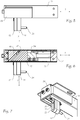
- Fig. 2 shows a cross section of the sliding door 1 in a sectional plane 8 according to the Fig. 1 , with only the uppermost part of the sliding door 1 being shown. It can be seen that a movable leaf in the form of a door leaf 20 is mounted in a door frame 30. Covers 3, 4 of the frame profiles of door 1 can be seen.
- FIG. 3 and 4 represent a main part 31 of the locking mechanism of the sliding door construction according to the Fig. 1 represents which can be integrated in the door frame 30.
- the main part 31 is arranged in the assembled state of the device in the door frame 30 of the door 1.
- a drive means 50 serves to move a sliding body 40 in a first direction 5 within the main part 31.
- the drive means 50 comprises a housing 51 with a linear drive in the form of a geared motor 52 and a push rod or a spindle 53.
- a push body 40 is fastened to the push rod.
- Sensor elements can be assigned to the drive means 50, each of which detects an end position of the movement of the sliding body 40 along the first direction 5.
- the sensor elements are preferably designed as reed switches.
- the individual components can be connected to each other using various screws or nuts, as in Fig. 4 indicated.
- the sliding body 40 comprises two side parts 43, 44, each of which has a groove 41 and 42, preferably on the side facing inwards.
- the side parts 43, 44 are connected via a nut 54, the nut 54 being provided to receive one end of the spindle 53.
- the sliding body 40 is U-shaped and also has cover plates 56 and 57 and an end cover 58.
- the main part 31 further comprises a holder 59 for fastening in the door frame 30.
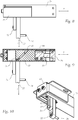
- the main part 31 has a lifting body 33 protruding from the main part 31, which is movably mounted in the main part 31 along a lifting direction 7 running transverse to the first direction 5.
- the locking device also has a lifting body 33 which projects downward from the main part 31 and serves to actuate the device.
- the lifting body 33 has an actuating element 34 projecting transversely to the lifting direction 7 in the form of a bolt.
- the bolt serves as a locking bolt, which is set up to engage in a locking device 21 of the door leaf 20 when the door leaf 20 ( Fig. 11 and 12th ) is brought into a closing position in the door frame 30 in order to lock the closing device 21 by a movement along the lifting direction 7.
- the sliding body 40 and the lifting body 33 are coupled to one another via a groove guide, which converts a movement of the sliding body 40 in the first direction 5 into a lifting movement of the lifting body 33 along the lifting direction 7.
- An optional guide block 55 is arranged between the nut 54 and the lifting body 33.
- the groove guide includes a groove 41, 42, preferably a straight groove, which runs obliquely to the first direction 5 and the stroke direction 7, and a sliding element 35 arranged therein.
- the lifting body 33 has, as a sliding element 35, two pins located opposite one another, each in one of the grooves 41, 42 intervene.
- the pins are designed as ends of a pin running through the lifting body 33 as a sliding element 35.
- the sliding body 40 has two side parts 43, 44 arranged on both sides of the lifting body 33, in each of which a groove 41, 42, preferably a straight groove, extending obliquely to the first direction 5 and the lifting direction 7 is formed.
- a guide body 32 Adjacent to the lifting body 33, a guide body 32 is arranged in parallel, which is attached to the main part 31 and fixed there.
- the guide body 32 has an elongated closing guide 37 with a longitudinal extent, into which a on the lifting body 33 attached stroke guide element 36 engages and the lifting body 33 is movable along the longitudinal extent of the closing guide 37 in the stroke direction 7.
- the elongated closing guide 37 forms a groove in which the stroke guide element 36, for example a cylinder with a mushroom-shaped end, can slide in the stroke direction 7 during a stroke movement.
- the length of the locking guide 37 limits the actuation path of the locking device 21.
- the actuating element 34 is arranged so as to protrude into a corresponding opening of the closing device 21 in the door.
- the actuating element 34 only engages in the closing device 21 of the door leaf 20 when the door leaf 20 is in the closed position.
- a first group of components such as the guide body 32, the side parts 43, 44 with the grooves 41 and 42 and the guide block 55, can be made of brass or anodized aluminum.
- a second group of components such as the lifting body 33, the actuating element 34 and the sliding element 35, can be made of stainless steel.
- the first group of components is made of a softer material than the second group of components because of the desired higher mechanical strength.
- FIG. 5 to 7 show the device with respect to the position of the lifting body 33 or the actuating element 34 in an unlocked state, which corresponds to a first end of the intended course of the linear movement.
- the lifting body 33 is in a position in which the outer edges of the lifting body 33 coincide with those of the adjacent guide body 32.
- the lifting body 33 is thus in a "retracted” state in the lifting direction 7.
- a rotary movement generated by the geared motor 52 is transmitted to the nut 54 by means of the spindle 53 and converted into a linear movement in the first direction 5 of the sliding body 40.
- Fig. 6 the sliding element 35 can be seen, which is located at the upper end of the groove 41. It can also be seen that the lifting body 33 is "retracted” to open the doors 1, 2.
- the linear movement causes the sliding element 35, which is mounted in the two grooves 41, 42, to move in the lifting direction 7.
- the lifting body 33 can be raised or lowered.
- the movement of the lifting body 33 is limited by the dimension and size of the closing guide 37, since the lifting guide element 36 attached to the lifting body 33 engages in the closing guide 37 and guides the lifting body 33 in the intended movement path, which is defined by the closing guide 37.
- the end position of the linear movement can be monitored by sensors, for example inductive or mechanical switches, but also optical sensors, as is known to the person skilled in the art.
- the geared motor 52 can be controlled by means of a corresponding control, but this is not shown in the figures.
- Fig. 9 the sliding element 35 can be seen, which is located at the lower end of the groove 41. It can also be seen that the lifting body 33 is "extended” for a closing operation.
- Fig. 11 and 12th each show a view of the sliding door arrangement of the two sliding doors 1 and 2 in the unlocked and locked state.
- the actuating element 34 engages in the closing device 21 located on the door side by means of the lifting body 33.
- the locking device 21 of the door 1 locks both doors to one another via a locking plate 60 of the door 2.
Landscapes
- Engineering & Computer Science (AREA)
- Civil Engineering (AREA)
- Structural Engineering (AREA)
- Physics & Mathematics (AREA)
- Electromagnetism (AREA)
- Power-Operated Mechanisms For Wings (AREA)
Claims (9)
- Dispositif, destiné à verrouiller un vantail de porte (20) déplaçable dans un chambranle (30) d'une porte (1, 2), notamment d'une porte coulissante mobile, lequel dispositif comprend :- une partie principale (31), laquelle lorsque le dispositif est monté est placée dans le chambranle (30) de la porte (1, 2), un corps coulissant (40) et un moyen d'entraînement (50) destiné à déplacer le corps coulissant (40) dans une première direction (5, 6) à l'intérieur de la partie principale (31), et- un corps de levage (33) saillant hors de la partie principale (31), lequel est logé en étant déplaçable dans la partie principale (31), le long d'une direction de levage (7) s'écoulant à la transversale de la première direction (5, 6), le corps de levage (33) comportant un élément d'actionnement (34) saillant à la transversale de la direction de levage (7) et aménagé pour s'engager dans un dispositif de fermeture (21) du vantail de porte (20), lorsque le vantail de porte (20) est amené dans une position de fermeture dans le chambranle (30), et pour verrouiller le dispositif de fermeture (21) par un déplacement le long de la direction de levage (7),le corps coulissant (40) et le corps de levage (33) étant accouplés l'un à l'autre par l'intermédiaire d'un guidage à rainure, lequel transforme un déplacement du corps coulissant (40) dans la première direction (5, 6) en un mouvement de levage du corps de levage (33) le long de la direction de levage (7).
- Dispositif selon la revendication 1, caractérisé en ce que le guidage à rainure comprend une rainure (41, 42), s'écoulant en oblique par rapport à la première direction (5, 6) et à la direction de levage (7), de préférence une rainure droite, et un coulisseau (35) placé dedans.
- Dispositif selon la revendication 2, caractérisé en ce que le corps coulissant (40) comporte deux parties latérales (43, 44) placées de part et d'autre du corps de levage (33), dans chacune desquelles est conçue une rainure (41, 42) s'écoulant en oblique par rapport à la première direction (5, 6) et à la direction de levage (7), de préférence une rainure droite, et le corps de levage (33) comporte en tant que coulisseau (35) deux tenons mutuellement opposés, lesquels s'engagent dans respectivement l'une des rainures (41, 42).
- Dispositif selon la revendication 3, caractérisé en ce que les tenons sont conçus sous la forme d'extrémités d'une tige s'écoulant à travers le corps de levage (33), en tant que coulisseau (35).
- Dispositif selon l'une quelconque des revendications précédentes, caractérisé en ce qu'un corps de guidage (32), lequel est monté sur la partie principale (31) et comporte un guide de fermeture (37) présentant une extension longitudinale, dans laquelle s'engage un élément de guidage en levage (36) monté sur le corps de levage (33), est placé en étant adjacent au corps de levage (33), et le corps de levage (33) est déplaçable le long de l'extension longitudinale du guide de fermeture (37) dans la direction de levage (7).
- Dispositif selon l'une quelconque des revendications précédentes, caractérisé en ce que lorsque le dispositif est monté, l'élément d'actionnement (34) est placé en saillant dans un orifice du dispositif de fermeture (21) dans la porte et ne s'engage dans le dispositif de fermeture (21) du vantail de porte (20) que dans la position de fermeture du vantail de porte (20)
- Dispositif selon l'une quelconque des revendications précédentes, caractérisé en ce que le moyen d'entraînement (50) comprend un entraînement linéaire pour une tige de poussée sur laquelle est fixé le corps coulissant (40).
- Dispositif selon l'une quelconque des revendications précédentes, caractérisé par des éléments capteurs associés au moyen d'entraînement (50), lesquels détectent respectivement une position extrême du déplacement du corps coulissant (40) le long de la première direction (5, 6), les éléments capteurs étant conçus de préférence en tant que commutateurs à lames.
- Porte (1, 2), notamment porte coulissante, pourvue d'un vantail de porte (20) déplaçable dans un chambranle (30) avec un dispositif de fermeture (21), à l'aide duquel le vantail de porte (20) est verrouillable en position fermée du vantail de porte (20), et avec un dispositif selon l'une quelconque des revendications précédentes, placé dans le chambranle (30).
Applications Claiming Priority (1)
| Application Number | Priority Date | Filing Date | Title |
|---|---|---|---|
| ATA51036/2017A AT520645B1 (de) | 2017-12-15 | 2017-12-15 | Verriegelungsvorrichtung für eine Tür, insbesondere Schiebetür |
Publications (2)
| Publication Number | Publication Date |
|---|---|
| EP3498960A1 EP3498960A1 (fr) | 2019-06-19 |
| EP3498960B1 true EP3498960B1 (fr) | 2020-07-15 |
Family
ID=64664975
Family Applications (1)
| Application Number | Title | Priority Date | Filing Date |
|---|---|---|---|
| EP18211849.7A Active EP3498960B1 (fr) | 2017-12-15 | 2018-12-12 | Dispositif de verrouillage pour une porte, en particulier une porte coulissante |
Country Status (2)
| Country | Link |
|---|---|
| EP (1) | EP3498960B1 (fr) |
| AT (1) | AT520645B1 (fr) |
Families Citing this family (2)
| Publication number | Priority date | Publication date | Assignee | Title |
|---|---|---|---|---|
| CN111335733B (zh) * | 2020-04-23 | 2023-08-01 | 魏超明 | 一种手动开关装置及平移门 |
| CN113775614B (zh) * | 2021-09-14 | 2023-03-03 | 海安奥克机械制造有限公司 | 一种防盗效果好的升降器材用锁紧装置 |
Family Cites Families (3)
| Publication number | Priority date | Publication date | Assignee | Title |
|---|---|---|---|---|
| FR2891296B1 (fr) * | 2005-09-26 | 2007-12-28 | Norsk Hydro As | Dispositif d'accrochage et de decrochage entre un coulissant et un montant. |
| DE102011089121B3 (de) * | 2011-12-20 | 2013-01-31 | Geze Gmbh | Verriegelungsvorrichtung für eine Schiebetür |
| DE102013222581A1 (de) * | 2013-11-07 | 2015-05-07 | Geze Gmbh | Verriegelungsvorrichtung |
-
2017
- 2017-12-15 AT ATA51036/2017A patent/AT520645B1/de not_active IP Right Cessation
-
2018
- 2018-12-12 EP EP18211849.7A patent/EP3498960B1/fr active Active
Non-Patent Citations (1)
| Title |
|---|
| None * |
Also Published As
| Publication number | Publication date |
|---|---|
| AT520645B1 (de) | 2019-06-15 |
| EP3498960A1 (fr) | 2019-06-19 |
| AT520645A4 (de) | 2019-06-15 |
Similar Documents
| Publication | Publication Date | Title |
|---|---|---|
| EP1816292B1 (fr) | Dispositif de verrouillage pour une ferrure de crémone | |
| EP2829679B1 (fr) | Ferrure pour l'appui d'un battant mobile contre une bordure fixe | |
| EP2166180B1 (fr) | Installation de fermeture | |
| DE19912717A1 (de) | Fenster oder Tür | |
| EP3102759B1 (fr) | Ferrure d'un battant de fenêtres ou de portes, au moins relevable et coulissant | |
| EP2476829B1 (fr) | Construction levante-coulissante, notamment porte levante-coulissante ou fenêtre levante-coulissante | |
| EP2682545B1 (fr) | Dispositif de fermeture pour une porte coulissante ou une fenêtre coulissante, et porte coulissante ou fenêtre coulissante | |
| EP3620602A1 (fr) | Dispositif d'ouverture et / ou de fermeture, ainsi que de verrouillage d'un état fermé d'un agencement de fermeture, de fermeture d'une ouverture de chambre, ainsi qu'agencement de fermeture doté d'un tel dispositif | |
| EP3498960B1 (fr) | Dispositif de verrouillage pour une porte, en particulier une porte coulissante | |
| DE202022100517U1 (de) | Profilanordnung eines Fensters oder einer Tür mit einem Flügelprofil, insbesondere einem Schiebeflügelprofil | |
| EP3060737B1 (fr) | Fenêtre ou porte équipée d'une ferrure | |
| EP0152791B1 (fr) | Dispositif de manoeuvre pour panneaux coulissants de fenêtres, portes ou similaires | |
| EP2146032A1 (fr) | Dispositif destiné à ouvrir et/ou fermer ainsi qu'à verrouiller un état fermé d'un dispositif de fermeture destiné à fermer une ouverture de salle ainsi que dispositif de fermeture doté d'un tel dispositif | |
| EP2520746B1 (fr) | Serrure actionnée de manière électrique | |
| EP3159466A1 (fr) | Verriegelungsvorrichtung mit zwei beweglichen verriegelungskörpern | |
| EP3859107B1 (fr) | Porte coulissante | |
| DE202022100514U1 (de) | Verlagerungsvorrichtung zur zwangsweisen Verlagerung eines Flügels, insbesondere eines Schiebeflügels, eines Fensters oder einer Tür | |
| EP1573157B1 (fr) | Dispositif pour porte coulissante et procédé pour fermer des portes coulissantes | |
| DE19900875C2 (de) | Verriegelungsvorrichtung für eine Türanlage | |
| EP3362627B1 (fr) | Entraînement à broche à verrouillage intégré | |
| DE102005014335A1 (de) | Verriegelungs-Vorrichtung für Türen | |
| EP2871312A1 (fr) | Dispositif d'aération par entrebâillement pour porte ou fenêtre coulissante et porte ou fenêtre coulissante | |
| EP3875714B1 (fr) | Dispositif de fenêtre coulissante | |
| EP3461974B1 (fr) | Mécanisme de verrouillage réglable pour une porte, en particulier pour une porte de véhicule | |
| DE202017001681U1 (de) | Schloss |
Legal Events
| Date | Code | Title | Description |
|---|---|---|---|
| PUAI | Public reference made under article 153(3) epc to a published international application that has entered the european phase |
Free format text: ORIGINAL CODE: 0009012 |
|
| STAA | Information on the status of an ep patent application or granted ep patent |
Free format text: STATUS: THE APPLICATION HAS BEEN PUBLISHED |
|
| AK | Designated contracting states |
Kind code of ref document: A1 Designated state(s): AL AT BE BG CH CY CZ DE DK EE ES FI FR GB GR HR HU IE IS IT LI LT LU LV MC MK MT NL NO PL PT RO RS SE SI SK SM TR |
|
| AX | Request for extension of the european patent |
Extension state: BA ME |
|
| STAA | Information on the status of an ep patent application or granted ep patent |
Free format text: STATUS: REQUEST FOR EXAMINATION WAS MADE |
|
| 17P | Request for examination filed |
Effective date: 20191203 |
|
| RBV | Designated contracting states (corrected) |
Designated state(s): AL AT BE BG CH CY CZ DE DK EE ES FI FR GB GR HR HU IE IS IT LI LT LU LV MC MK MT NL NO PL PT RO RS SE SI SK SM TR |
|
| GRAP | Despatch of communication of intention to grant a patent |
Free format text: ORIGINAL CODE: EPIDOSNIGR1 |
|
| STAA | Information on the status of an ep patent application or granted ep patent |
Free format text: STATUS: GRANT OF PATENT IS INTENDED |
|
| INTG | Intention to grant announced |
Effective date: 20200205 |
|
| GRAS | Grant fee paid |
Free format text: ORIGINAL CODE: EPIDOSNIGR3 |
|
| GRAA | (expected) grant |
Free format text: ORIGINAL CODE: 0009210 |
|
| STAA | Information on the status of an ep patent application or granted ep patent |
Free format text: STATUS: THE PATENT HAS BEEN GRANTED |
|
| AK | Designated contracting states |
Kind code of ref document: B1 Designated state(s): AL AT BE BG CH CY CZ DE DK EE ES FI FR GB GR HR HU IE IS IT LI LT LU LV MC MK MT NL NO PL PT RO RS SE SI SK SM TR |
|
| RAP1 | Party data changed (applicant data changed or rights of an application transferred) |
Owner name: LIBERDA, VIKTOR Owner name: LIBERDA, RUDOLF |
|
| REG | Reference to a national code |
Ref country code: GB Ref legal event code: FG4D Free format text: NOT ENGLISH Ref country code: CH Ref legal event code: EP |
|
| REG | Reference to a national code |
Ref country code: IE Ref legal event code: FG4D Free format text: LANGUAGE OF EP DOCUMENT: GERMAN |
|
| REG | Reference to a national code |
Ref country code: DE Ref legal event code: R096 Ref document number: 502018001903 Country of ref document: DE |
|
| REG | Reference to a national code |
Ref country code: AT Ref legal event code: REF Ref document number: 1291224 Country of ref document: AT Kind code of ref document: T Effective date: 20200815 |
|
| REG | Reference to a national code |
Ref country code: LT Ref legal event code: MG4D |
|
| REG | Reference to a national code |
Ref country code: NL Ref legal event code: MP Effective date: 20200715 |
|
| PG25 | Lapsed in a contracting state [announced via postgrant information from national office to epo] |
Ref country code: GR Free format text: LAPSE BECAUSE OF FAILURE TO SUBMIT A TRANSLATION OF THE DESCRIPTION OR TO PAY THE FEE WITHIN THE PRESCRIBED TIME-LIMIT Effective date: 20201016 Ref country code: FI Free format text: LAPSE BECAUSE OF FAILURE TO SUBMIT A TRANSLATION OF THE DESCRIPTION OR TO PAY THE FEE WITHIN THE PRESCRIBED TIME-LIMIT Effective date: 20200715 Ref country code: NO Free format text: LAPSE BECAUSE OF FAILURE TO SUBMIT A TRANSLATION OF THE DESCRIPTION OR TO PAY THE FEE WITHIN THE PRESCRIBED TIME-LIMIT Effective date: 20201015 Ref country code: SE Free format text: LAPSE BECAUSE OF FAILURE TO SUBMIT A TRANSLATION OF THE DESCRIPTION OR TO PAY THE FEE WITHIN THE PRESCRIBED TIME-LIMIT Effective date: 20200715 Ref country code: ES Free format text: LAPSE BECAUSE OF FAILURE TO SUBMIT A TRANSLATION OF THE DESCRIPTION OR TO PAY THE FEE WITHIN THE PRESCRIBED TIME-LIMIT Effective date: 20200715 Ref country code: LT Free format text: LAPSE BECAUSE OF FAILURE TO SUBMIT A TRANSLATION OF THE DESCRIPTION OR TO PAY THE FEE WITHIN THE PRESCRIBED TIME-LIMIT Effective date: 20200715 Ref country code: BG Free format text: LAPSE BECAUSE OF FAILURE TO SUBMIT A TRANSLATION OF THE DESCRIPTION OR TO PAY THE FEE WITHIN THE PRESCRIBED TIME-LIMIT Effective date: 20201015 Ref country code: HR Free format text: LAPSE BECAUSE OF FAILURE TO SUBMIT A TRANSLATION OF THE DESCRIPTION OR TO PAY THE FEE WITHIN THE PRESCRIBED TIME-LIMIT Effective date: 20200715 Ref country code: PT Free format text: LAPSE BECAUSE OF FAILURE TO SUBMIT A TRANSLATION OF THE DESCRIPTION OR TO PAY THE FEE WITHIN THE PRESCRIBED TIME-LIMIT Effective date: 20201116 |
|
| PGFP | Annual fee paid to national office [announced via postgrant information from national office to epo] |
Ref country code: FR Payment date: 20201223 Year of fee payment: 3 |
|
| PG25 | Lapsed in a contracting state [announced via postgrant information from national office to epo] |
Ref country code: IS Free format text: LAPSE BECAUSE OF FAILURE TO SUBMIT A TRANSLATION OF THE DESCRIPTION OR TO PAY THE FEE WITHIN THE PRESCRIBED TIME-LIMIT Effective date: 20201115 Ref country code: PL Free format text: LAPSE BECAUSE OF FAILURE TO SUBMIT A TRANSLATION OF THE DESCRIPTION OR TO PAY THE FEE WITHIN THE PRESCRIBED TIME-LIMIT Effective date: 20200715 Ref country code: LV Free format text: LAPSE BECAUSE OF FAILURE TO SUBMIT A TRANSLATION OF THE DESCRIPTION OR TO PAY THE FEE WITHIN THE PRESCRIBED TIME-LIMIT Effective date: 20200715 Ref country code: RS Free format text: LAPSE BECAUSE OF FAILURE TO SUBMIT A TRANSLATION OF THE DESCRIPTION OR TO PAY THE FEE WITHIN THE PRESCRIBED TIME-LIMIT Effective date: 20200715 |
|
| PG25 | Lapsed in a contracting state [announced via postgrant information from national office to epo] |
Ref country code: NL Free format text: LAPSE BECAUSE OF FAILURE TO SUBMIT A TRANSLATION OF THE DESCRIPTION OR TO PAY THE FEE WITHIN THE PRESCRIBED TIME-LIMIT Effective date: 20200715 |
|
| REG | Reference to a national code |
Ref country code: DE Ref legal event code: R097 Ref document number: 502018001903 Country of ref document: DE |
|
| PG25 | Lapsed in a contracting state [announced via postgrant information from national office to epo] |
Ref country code: CZ Free format text: LAPSE BECAUSE OF FAILURE TO SUBMIT A TRANSLATION OF THE DESCRIPTION OR TO PAY THE FEE WITHIN THE PRESCRIBED TIME-LIMIT Effective date: 20200715 Ref country code: DK Free format text: LAPSE BECAUSE OF FAILURE TO SUBMIT A TRANSLATION OF THE DESCRIPTION OR TO PAY THE FEE WITHIN THE PRESCRIBED TIME-LIMIT Effective date: 20200715 Ref country code: RO Free format text: LAPSE BECAUSE OF FAILURE TO SUBMIT A TRANSLATION OF THE DESCRIPTION OR TO PAY THE FEE WITHIN THE PRESCRIBED TIME-LIMIT Effective date: 20200715 Ref country code: EE Free format text: LAPSE BECAUSE OF FAILURE TO SUBMIT A TRANSLATION OF THE DESCRIPTION OR TO PAY THE FEE WITHIN THE PRESCRIBED TIME-LIMIT Effective date: 20200715 Ref country code: IT Free format text: LAPSE BECAUSE OF FAILURE TO SUBMIT A TRANSLATION OF THE DESCRIPTION OR TO PAY THE FEE WITHIN THE PRESCRIBED TIME-LIMIT Effective date: 20200715 Ref country code: SM Free format text: LAPSE BECAUSE OF FAILURE TO SUBMIT A TRANSLATION OF THE DESCRIPTION OR TO PAY THE FEE WITHIN THE PRESCRIBED TIME-LIMIT Effective date: 20200715 |
|
| PLBE | No opposition filed within time limit |
Free format text: ORIGINAL CODE: 0009261 |
|
| STAA | Information on the status of an ep patent application or granted ep patent |
Free format text: STATUS: NO OPPOSITION FILED WITHIN TIME LIMIT |
|
| PG25 | Lapsed in a contracting state [announced via postgrant information from national office to epo] |
Ref country code: AL Free format text: LAPSE BECAUSE OF FAILURE TO SUBMIT A TRANSLATION OF THE DESCRIPTION OR TO PAY THE FEE WITHIN THE PRESCRIBED TIME-LIMIT Effective date: 20200715 |
|
| PGFP | Annual fee paid to national office [announced via postgrant information from national office to epo] |
Ref country code: DE Payment date: 20201221 Year of fee payment: 3 |
|
| 26N | No opposition filed |
Effective date: 20210416 |
|
| PG25 | Lapsed in a contracting state [announced via postgrant information from national office to epo] |
Ref country code: SK Free format text: LAPSE BECAUSE OF FAILURE TO SUBMIT A TRANSLATION OF THE DESCRIPTION OR TO PAY THE FEE WITHIN THE PRESCRIBED TIME-LIMIT Effective date: 20200715 |
|
| PG25 | Lapsed in a contracting state [announced via postgrant information from national office to epo] |
Ref country code: SI Free format text: LAPSE BECAUSE OF FAILURE TO SUBMIT A TRANSLATION OF THE DESCRIPTION OR TO PAY THE FEE WITHIN THE PRESCRIBED TIME-LIMIT Effective date: 20200715 Ref country code: MC Free format text: LAPSE BECAUSE OF FAILURE TO SUBMIT A TRANSLATION OF THE DESCRIPTION OR TO PAY THE FEE WITHIN THE PRESCRIBED TIME-LIMIT Effective date: 20200715 |
|
| REG | Reference to a national code |
Ref country code: BE Ref legal event code: MM Effective date: 20201231 |
|
| PG25 | Lapsed in a contracting state [announced via postgrant information from national office to epo] |
Ref country code: IE Free format text: LAPSE BECAUSE OF NON-PAYMENT OF DUE FEES Effective date: 20201212 Ref country code: LU Free format text: LAPSE BECAUSE OF NON-PAYMENT OF DUE FEES Effective date: 20201212 |
|
| PG25 | Lapsed in a contracting state [announced via postgrant information from national office to epo] |
Ref country code: TR Free format text: LAPSE BECAUSE OF FAILURE TO SUBMIT A TRANSLATION OF THE DESCRIPTION OR TO PAY THE FEE WITHIN THE PRESCRIBED TIME-LIMIT Effective date: 20200715 Ref country code: MT Free format text: LAPSE BECAUSE OF FAILURE TO SUBMIT A TRANSLATION OF THE DESCRIPTION OR TO PAY THE FEE WITHIN THE PRESCRIBED TIME-LIMIT Effective date: 20200715 Ref country code: CY Free format text: LAPSE BECAUSE OF FAILURE TO SUBMIT A TRANSLATION OF THE DESCRIPTION OR TO PAY THE FEE WITHIN THE PRESCRIBED TIME-LIMIT Effective date: 20200715 |
|
| PG25 | Lapsed in a contracting state [announced via postgrant information from national office to epo] |
Ref country code: MK Free format text: LAPSE BECAUSE OF FAILURE TO SUBMIT A TRANSLATION OF THE DESCRIPTION OR TO PAY THE FEE WITHIN THE PRESCRIBED TIME-LIMIT Effective date: 20200715 |
|
| REG | Reference to a national code |
Ref country code: DE Ref legal event code: R119 Ref document number: 502018001903 Country of ref document: DE |
|
| PG25 | Lapsed in a contracting state [announced via postgrant information from national office to epo] |
Ref country code: BE Free format text: LAPSE BECAUSE OF NON-PAYMENT OF DUE FEES Effective date: 20201231 |
|
| REG | Reference to a national code |
Ref country code: CH Ref legal event code: PL |
|
| PG25 | Lapsed in a contracting state [announced via postgrant information from national office to epo] |
Ref country code: DE Free format text: LAPSE BECAUSE OF NON-PAYMENT OF DUE FEES Effective date: 20220701 |
|
| PG25 | Lapsed in a contracting state [announced via postgrant information from national office to epo] |
Ref country code: FR Free format text: LAPSE BECAUSE OF NON-PAYMENT OF DUE FEES Effective date: 20211231 |
|
| PG25 | Lapsed in a contracting state [announced via postgrant information from national office to epo] |
Ref country code: LI Free format text: LAPSE BECAUSE OF NON-PAYMENT OF DUE FEES Effective date: 20211231 Ref country code: CH Free format text: LAPSE BECAUSE OF NON-PAYMENT OF DUE FEES Effective date: 20211231 |
|
| GBPC | Gb: european patent ceased through non-payment of renewal fee |
Effective date: 20221212 |
|
| PG25 | Lapsed in a contracting state [announced via postgrant information from national office to epo] |
Ref country code: GB Free format text: LAPSE BECAUSE OF NON-PAYMENT OF DUE FEES Effective date: 20221212 |
|
| PGFP | Annual fee paid to national office [announced via postgrant information from national office to epo] |
Ref country code: AT Payment date: 20231228 Year of fee payment: 6 |