EP3680565A1 - Dispositif de climatisation - Google Patents
Dispositif de climatisation Download PDFInfo
- Publication number
- EP3680565A1 EP3680565A1 EP17923991.8A EP17923991A EP3680565A1 EP 3680565 A1 EP3680565 A1 EP 3680565A1 EP 17923991 A EP17923991 A EP 17923991A EP 3680565 A1 EP3680565 A1 EP 3680565A1
- Authority
- EP
- European Patent Office
- Prior art keywords
- pipe
- flow path
- heat exchanger
- refrigerant
- compressor
- Prior art date
- Legal status (The legal status is an assumption and is not a legal conclusion. Google has not performed a legal analysis and makes no representation as to the accuracy of the status listed.)
- Granted
Links
- 238000004378 air conditioning Methods 0.000 title claims abstract description 37
- 239000003507 refrigerant Substances 0.000 claims abstract description 203
- 238000004781 supercooling Methods 0.000 claims abstract description 89
- 238000001816 cooling Methods 0.000 claims abstract description 67
- 230000001105 regulatory effect Effects 0.000 claims abstract description 56
- 238000010438 heat treatment Methods 0.000 claims description 30
- 230000002596 correlated effect Effects 0.000 claims description 6
- 239000007788 liquid Substances 0.000 description 56
- 239000012071 phase Substances 0.000 description 18
- 230000003247 decreasing effect Effects 0.000 description 9
- 230000008859 change Effects 0.000 description 8
- 239000007791 liquid phase Substances 0.000 description 8
- 230000000875 corresponding effect Effects 0.000 description 6
- 230000009467 reduction Effects 0.000 description 6
- 238000000034 method Methods 0.000 description 4
- 230000001276 controlling effect Effects 0.000 description 3
- 238000011144 upstream manufacturing Methods 0.000 description 3
- 238000009826 distribution Methods 0.000 description 2
- 230000000694 effects Effects 0.000 description 2
- 230000004048 modification Effects 0.000 description 2
- 238000012986 modification Methods 0.000 description 2
- 238000009434 installation Methods 0.000 description 1
- 238000004519 manufacturing process Methods 0.000 description 1
- 230000008569 process Effects 0.000 description 1
- 238000003860 storage Methods 0.000 description 1
Images


Classifications
-
- F—MECHANICAL ENGINEERING; LIGHTING; HEATING; WEAPONS; BLASTING
- F24—HEATING; RANGES; VENTILATING
- F24F—AIR-CONDITIONING; AIR-HUMIDIFICATION; VENTILATION; USE OF AIR CURRENTS FOR SCREENING
- F24F11/00—Control or safety arrangements
- F24F11/30—Control or safety arrangements for purposes related to the operation of the system, e.g. for safety or monitoring
- F24F11/49—Control or safety arrangements for purposes related to the operation of the system, e.g. for safety or monitoring ensuring correct operation, e.g. by trial operation or configuration checks
-
- F—MECHANICAL ENGINEERING; LIGHTING; HEATING; WEAPONS; BLASTING
- F24—HEATING; RANGES; VENTILATING
- F24F—AIR-CONDITIONING; AIR-HUMIDIFICATION; VENTILATION; USE OF AIR CURRENTS FOR SCREENING
- F24F1/00—Room units for air-conditioning, e.g. separate or self-contained units or units receiving primary air from a central station
- F24F1/0007—Indoor units, e.g. fan coil units
- F24F1/0059—Indoor units, e.g. fan coil units characterised by heat exchangers
-
- F—MECHANICAL ENGINEERING; LIGHTING; HEATING; WEAPONS; BLASTING
- F24—HEATING; RANGES; VENTILATING
- F24F—AIR-CONDITIONING; AIR-HUMIDIFICATION; VENTILATION; USE OF AIR CURRENTS FOR SCREENING
- F24F1/00—Room units for air-conditioning, e.g. separate or self-contained units or units receiving primary air from a central station
- F24F1/06—Separate outdoor units, e.g. outdoor unit to be linked to a separate room comprising a compressor and a heat exchanger
- F24F1/26—Refrigerant piping
- F24F1/32—Refrigerant piping for connecting the separate outdoor units to indoor units
-
- F—MECHANICAL ENGINEERING; LIGHTING; HEATING; WEAPONS; BLASTING
- F24—HEATING; RANGES; VENTILATING
- F24F—AIR-CONDITIONING; AIR-HUMIDIFICATION; VENTILATION; USE OF AIR CURRENTS FOR SCREENING
- F24F11/00—Control or safety arrangements
- F24F11/70—Control systems characterised by their outputs; Constructional details thereof
- F24F11/72—Control systems characterised by their outputs; Constructional details thereof for controlling the supply of treated air, e.g. its pressure
- F24F11/74—Control systems characterised by their outputs; Constructional details thereof for controlling the supply of treated air, e.g. its pressure for controlling air flow rate or air velocity
- F24F11/75—Control systems characterised by their outputs; Constructional details thereof for controlling the supply of treated air, e.g. its pressure for controlling air flow rate or air velocity for maintaining constant air flow rate or air velocity
-
- F—MECHANICAL ENGINEERING; LIGHTING; HEATING; WEAPONS; BLASTING
- F24—HEATING; RANGES; VENTILATING
- F24F—AIR-CONDITIONING; AIR-HUMIDIFICATION; VENTILATION; USE OF AIR CURRENTS FOR SCREENING
- F24F11/00—Control or safety arrangements
- F24F11/70—Control systems characterised by their outputs; Constructional details thereof
- F24F11/80—Control systems characterised by their outputs; Constructional details thereof for controlling the temperature of the supplied air
- F24F11/83—Control systems characterised by their outputs; Constructional details thereof for controlling the temperature of the supplied air by controlling the supply of heat-exchange fluids to heat-exchangers
- F24F11/84—Control systems characterised by their outputs; Constructional details thereof for controlling the temperature of the supplied air by controlling the supply of heat-exchange fluids to heat-exchangers using valves
-
- F—MECHANICAL ENGINEERING; LIGHTING; HEATING; WEAPONS; BLASTING
- F24—HEATING; RANGES; VENTILATING
- F24F—AIR-CONDITIONING; AIR-HUMIDIFICATION; VENTILATION; USE OF AIR CURRENTS FOR SCREENING
- F24F11/00—Control or safety arrangements
- F24F11/70—Control systems characterised by their outputs; Constructional details thereof
- F24F11/80—Control systems characterised by their outputs; Constructional details thereof for controlling the temperature of the supplied air
- F24F11/86—Control systems characterised by their outputs; Constructional details thereof for controlling the temperature of the supplied air by controlling compressors within refrigeration or heat pump circuits
-
- F—MECHANICAL ENGINEERING; LIGHTING; HEATING; WEAPONS; BLASTING
- F25—REFRIGERATION OR COOLING; COMBINED HEATING AND REFRIGERATION SYSTEMS; HEAT PUMP SYSTEMS; MANUFACTURE OR STORAGE OF ICE; LIQUEFACTION SOLIDIFICATION OF GASES
- F25B—REFRIGERATION MACHINES, PLANTS OR SYSTEMS; COMBINED HEATING AND REFRIGERATION SYSTEMS; HEAT PUMP SYSTEMS
- F25B13/00—Compression machines, plants or systems, with reversible cycle
-
- F—MECHANICAL ENGINEERING; LIGHTING; HEATING; WEAPONS; BLASTING
- F25—REFRIGERATION OR COOLING; COMBINED HEATING AND REFRIGERATION SYSTEMS; HEAT PUMP SYSTEMS; MANUFACTURE OR STORAGE OF ICE; LIQUEFACTION SOLIDIFICATION OF GASES
- F25B—REFRIGERATION MACHINES, PLANTS OR SYSTEMS; COMBINED HEATING AND REFRIGERATION SYSTEMS; HEAT PUMP SYSTEMS
- F25B40/00—Subcoolers, desuperheaters or superheaters
- F25B40/02—Subcoolers
-
- F—MECHANICAL ENGINEERING; LIGHTING; HEATING; WEAPONS; BLASTING
- F25—REFRIGERATION OR COOLING; COMBINED HEATING AND REFRIGERATION SYSTEMS; HEAT PUMP SYSTEMS; MANUFACTURE OR STORAGE OF ICE; LIQUEFACTION SOLIDIFICATION OF GASES
- F25B—REFRIGERATION MACHINES, PLANTS OR SYSTEMS; COMBINED HEATING AND REFRIGERATION SYSTEMS; HEAT PUMP SYSTEMS
- F25B40/00—Subcoolers, desuperheaters or superheaters
- F25B40/06—Superheaters
-
- F—MECHANICAL ENGINEERING; LIGHTING; HEATING; WEAPONS; BLASTING
- F25—REFRIGERATION OR COOLING; COMBINED HEATING AND REFRIGERATION SYSTEMS; HEAT PUMP SYSTEMS; MANUFACTURE OR STORAGE OF ICE; LIQUEFACTION SOLIDIFICATION OF GASES
- F25B—REFRIGERATION MACHINES, PLANTS OR SYSTEMS; COMBINED HEATING AND REFRIGERATION SYSTEMS; HEAT PUMP SYSTEMS
- F25B49/00—Arrangement or mounting of control or safety devices
- F25B49/02—Arrangement or mounting of control or safety devices for compression type machines, plants or systems
-
- F—MECHANICAL ENGINEERING; LIGHTING; HEATING; WEAPONS; BLASTING
- F24—HEATING; RANGES; VENTILATING
- F24F—AIR-CONDITIONING; AIR-HUMIDIFICATION; VENTILATION; USE OF AIR CURRENTS FOR SCREENING
- F24F2110/00—Control inputs relating to air properties
- F24F2110/40—Pressure, e.g. wind pressure
-
- F—MECHANICAL ENGINEERING; LIGHTING; HEATING; WEAPONS; BLASTING
- F25—REFRIGERATION OR COOLING; COMBINED HEATING AND REFRIGERATION SYSTEMS; HEAT PUMP SYSTEMS; MANUFACTURE OR STORAGE OF ICE; LIQUEFACTION SOLIDIFICATION OF GASES
- F25B—REFRIGERATION MACHINES, PLANTS OR SYSTEMS; COMBINED HEATING AND REFRIGERATION SYSTEMS; HEAT PUMP SYSTEMS
- F25B2313/00—Compression machines, plants or systems with reversible cycle not otherwise provided for
- F25B2313/023—Compression machines, plants or systems with reversible cycle not otherwise provided for using multiple indoor units
- F25B2313/0233—Compression machines, plants or systems with reversible cycle not otherwise provided for using multiple indoor units in parallel arrangements
-
- F—MECHANICAL ENGINEERING; LIGHTING; HEATING; WEAPONS; BLASTING
- F25—REFRIGERATION OR COOLING; COMBINED HEATING AND REFRIGERATION SYSTEMS; HEAT PUMP SYSTEMS; MANUFACTURE OR STORAGE OF ICE; LIQUEFACTION SOLIDIFICATION OF GASES
- F25B—REFRIGERATION MACHINES, PLANTS OR SYSTEMS; COMBINED HEATING AND REFRIGERATION SYSTEMS; HEAT PUMP SYSTEMS
- F25B2313/00—Compression machines, plants or systems with reversible cycle not otherwise provided for
- F25B2313/027—Compression machines, plants or systems with reversible cycle not otherwise provided for characterised by the reversing means
- F25B2313/02741—Compression machines, plants or systems with reversible cycle not otherwise provided for characterised by the reversing means using one four-way valve
-
- F—MECHANICAL ENGINEERING; LIGHTING; HEATING; WEAPONS; BLASTING
- F25—REFRIGERATION OR COOLING; COMBINED HEATING AND REFRIGERATION SYSTEMS; HEAT PUMP SYSTEMS; MANUFACTURE OR STORAGE OF ICE; LIQUEFACTION SOLIDIFICATION OF GASES
- F25B—REFRIGERATION MACHINES, PLANTS OR SYSTEMS; COMBINED HEATING AND REFRIGERATION SYSTEMS; HEAT PUMP SYSTEMS
- F25B2400/00—General features or devices for refrigeration machines, plants or systems, combined heating and refrigeration systems or heat-pump systems, i.e. not limited to a particular subgroup of F25B
- F25B2400/04—Refrigeration circuit bypassing means
- F25B2400/0409—Refrigeration circuit bypassing means for the evaporator
-
- F—MECHANICAL ENGINEERING; LIGHTING; HEATING; WEAPONS; BLASTING
- F25—REFRIGERATION OR COOLING; COMBINED HEATING AND REFRIGERATION SYSTEMS; HEAT PUMP SYSTEMS; MANUFACTURE OR STORAGE OF ICE; LIQUEFACTION SOLIDIFICATION OF GASES
- F25B—REFRIGERATION MACHINES, PLANTS OR SYSTEMS; COMBINED HEATING AND REFRIGERATION SYSTEMS; HEAT PUMP SYSTEMS
- F25B2400/00—General features or devices for refrigeration machines, plants or systems, combined heating and refrigeration systems or heat-pump systems, i.e. not limited to a particular subgroup of F25B
- F25B2400/04—Refrigeration circuit bypassing means
- F25B2400/0417—Refrigeration circuit bypassing means for the subcooler
-
- F—MECHANICAL ENGINEERING; LIGHTING; HEATING; WEAPONS; BLASTING
- F25—REFRIGERATION OR COOLING; COMBINED HEATING AND REFRIGERATION SYSTEMS; HEAT PUMP SYSTEMS; MANUFACTURE OR STORAGE OF ICE; LIQUEFACTION SOLIDIFICATION OF GASES
- F25B—REFRIGERATION MACHINES, PLANTS OR SYSTEMS; COMBINED HEATING AND REFRIGERATION SYSTEMS; HEAT PUMP SYSTEMS
- F25B2400/00—General features or devices for refrigeration machines, plants or systems, combined heating and refrigeration systems or heat-pump systems, i.e. not limited to a particular subgroup of F25B
- F25B2400/04—Refrigeration circuit bypassing means
- F25B2400/0419—Refrigeration circuit bypassing means for the superheater
-
- F—MECHANICAL ENGINEERING; LIGHTING; HEATING; WEAPONS; BLASTING
- F25—REFRIGERATION OR COOLING; COMBINED HEATING AND REFRIGERATION SYSTEMS; HEAT PUMP SYSTEMS; MANUFACTURE OR STORAGE OF ICE; LIQUEFACTION SOLIDIFICATION OF GASES
- F25B—REFRIGERATION MACHINES, PLANTS OR SYSTEMS; COMBINED HEATING AND REFRIGERATION SYSTEMS; HEAT PUMP SYSTEMS
- F25B2400/00—General features or devices for refrigeration machines, plants or systems, combined heating and refrigeration systems or heat-pump systems, i.e. not limited to a particular subgroup of F25B
- F25B2400/05—Compression system with heat exchange between particular parts of the system
- F25B2400/054—Compression system with heat exchange between particular parts of the system between the suction tube of the compressor and another part of the cycle
-
- F—MECHANICAL ENGINEERING; LIGHTING; HEATING; WEAPONS; BLASTING
- F25—REFRIGERATION OR COOLING; COMBINED HEATING AND REFRIGERATION SYSTEMS; HEAT PUMP SYSTEMS; MANUFACTURE OR STORAGE OF ICE; LIQUEFACTION SOLIDIFICATION OF GASES
- F25B—REFRIGERATION MACHINES, PLANTS OR SYSTEMS; COMBINED HEATING AND REFRIGERATION SYSTEMS; HEAT PUMP SYSTEMS
- F25B2400/00—General features or devices for refrigeration machines, plants or systems, combined heating and refrigeration systems or heat-pump systems, i.e. not limited to a particular subgroup of F25B
- F25B2400/13—Economisers
-
- F—MECHANICAL ENGINEERING; LIGHTING; HEATING; WEAPONS; BLASTING
- F25—REFRIGERATION OR COOLING; COMBINED HEATING AND REFRIGERATION SYSTEMS; HEAT PUMP SYSTEMS; MANUFACTURE OR STORAGE OF ICE; LIQUEFACTION SOLIDIFICATION OF GASES
- F25B—REFRIGERATION MACHINES, PLANTS OR SYSTEMS; COMBINED HEATING AND REFRIGERATION SYSTEMS; HEAT PUMP SYSTEMS
- F25B2600/00—Control issues
- F25B2600/25—Control of valves
- F25B2600/2501—Bypass valves
-
- F—MECHANICAL ENGINEERING; LIGHTING; HEATING; WEAPONS; BLASTING
- F25—REFRIGERATION OR COOLING; COMBINED HEATING AND REFRIGERATION SYSTEMS; HEAT PUMP SYSTEMS; MANUFACTURE OR STORAGE OF ICE; LIQUEFACTION SOLIDIFICATION OF GASES
- F25B—REFRIGERATION MACHINES, PLANTS OR SYSTEMS; COMBINED HEATING AND REFRIGERATION SYSTEMS; HEAT PUMP SYSTEMS
- F25B2600/00—Control issues
- F25B2600/25—Control of valves
- F25B2600/2519—On-off valves
-
- F—MECHANICAL ENGINEERING; LIGHTING; HEATING; WEAPONS; BLASTING
- F25—REFRIGERATION OR COOLING; COMBINED HEATING AND REFRIGERATION SYSTEMS; HEAT PUMP SYSTEMS; MANUFACTURE OR STORAGE OF ICE; LIQUEFACTION SOLIDIFICATION OF GASES
- F25B—REFRIGERATION MACHINES, PLANTS OR SYSTEMS; COMBINED HEATING AND REFRIGERATION SYSTEMS; HEAT PUMP SYSTEMS
- F25B2700/00—Sensing or detecting of parameters; Sensors therefor
- F25B2700/13—Mass flow of refrigerants
-
- F—MECHANICAL ENGINEERING; LIGHTING; HEATING; WEAPONS; BLASTING
- F25—REFRIGERATION OR COOLING; COMBINED HEATING AND REFRIGERATION SYSTEMS; HEAT PUMP SYSTEMS; MANUFACTURE OR STORAGE OF ICE; LIQUEFACTION SOLIDIFICATION OF GASES
- F25B—REFRIGERATION MACHINES, PLANTS OR SYSTEMS; COMBINED HEATING AND REFRIGERATION SYSTEMS; HEAT PUMP SYSTEMS
- F25B41/00—Fluid-circulation arrangements
- F25B41/40—Fluid line arrangements
- F25B41/42—Arrangements for diverging or converging flows, e.g. branch lines or junctions
Definitions
- the present disclosure relates to an air conditioning apparatus, particularly, an air conditioning apparatus including a heat exchanger for supercooling refrigerant at an upstream side relative to an expansion valve during a cooling operation.
- an air conditioning apparatus in which a plurality of indoor units are connected to one outdoor unit in parallel.
- an expansion valve is disposed in the indoor unit. Only liquid-phase refrigerant desirably flows into the expansion valve.
- two-phase refrigerant including both a liquid phase and a gas phase flows into the expansion valve, the liquid phase and the gas phase alternately pass discontinuously to cause a pressure fluctuation, thus resulting in generation of a refrigerant sound from the expansion valve.
- a technique for providing a heat exchanger for supercooling the refrigerant at an upstream side relative to the expansion valve In order to suppress the generation of such a refrigerant sound, there has been developed a technique for providing a heat exchanger for supercooling the refrigerant at an upstream side relative to the expansion valve.
- Patent Literature 1 discloses a supercooling heat exchanger configured to supercool high-pressure refrigerant during a cooling operation by exchanging heat between high-pressure refrigerant flowing from the outdoor heat exchanger into the expansion valve and low-pressure refrigerant flowing from the indoor heat exchanger into the compressor.
- Patent Literature 2 discloses a supercooling heat exchanger configured to supercool mainstream refrigerant by exchanging heat between low-pressure bypass flow refrigerant and high-pressure mainstream refrigerant.
- the low-pressure bypass flow refrigerant is branched from a main circuit between a condenser and an expansion valve and passes through a capillary tube.
- the high-pressure mainstream refrigerant flows in the main circuit.
- An object of the present disclosure is to provide an air conditioning apparatus that can suppress increase of pressure loss between an indoor heat exchanger and a compressor and that can suppress generation of a refrigerant sound in an expansion valve.
- An air conditioning apparatus includes: an outdoor unit including a compressor and an outdoor heat exchanger; at least one indoor unit including an expansion valve and an indoor heat exchanger; and a main circuit configured to circulate refrigerant through the compressor, the outdoor heat exchanger, the expansion valve, and the indoor heat exchanger.
- the main circuit includes a first flow path between the outdoor heat exchanger and the expansion valve.
- the air conditioning apparatus further includes a supercooling heat exchanger configured to supercool the refrigerant flowing in the first flow path.
- the main circuit includes a second flow path that does not extend through the supercooling heat exchanger, and a third flow path that extends through the supercooling heat exchanger.
- the air conditioning apparatus further includes a flow path switching valve, a bypass circuit, a bypass regulating valve, and a controller.
- the flow path switching valve is configured to switch, to one of the second flow path and the third flow path, the flow path between the indoor heat exchanger and the compressor.
- the bypass circuit is branched from the first flow path, extends through the supercooling heat exchanger, and is joined to the main circuit.
- the bypass regulating valve is provided in the bypass circuit.
- the controller is configured to control the flow path switching valve and the bypass regulating valve.
- the controller In a cooling operation, when a parameter correlated with a flow rate of the refrigerant in the main circuit indicates that the flow rate of the refrigerant is more than a reference value, the controller is configured to control the flow path switching valve to switch, to the second flow path, the flow path between the indoor heat exchanger and the compressor, and open the bypass regulating valve. In the cooling operation, when the parameter indicates that the flow rate of the refrigerant is less than the reference value, the controller is configured to control the flow path switching valve to switch, to the third flow path, the flow path between the indoor heat exchanger and the compressor, and close the bypass regulating valve.
- the bypass regulating valve in the case where the load is low, i.e., in the case where the parameter indicates that the flow rate of the refrigerant is less than the reference value, the bypass regulating valve is closed. Hence, an amount of absorbed heat of the refrigerant from the supercooling heat exchanger to the expansion valve can be suppressed, whereby a refrigerant sound generated from the expansion valve can be suppressed.
- the load is not low, i.e., in the case where the parameter indicates that the flow rate of the refrigerant is more than the reference value
- the flow path between the indoor heat exchanger and the compressor is switched to the second flow path that does not extend through the supercooling heat exchanger.
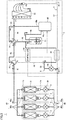
- FIG. 1 shows an air conditioning apparatus 1 according to an embodiment.
- air conditioning apparatus 1 includes: an outdoor unit 2 including a compressor 20 and an outdoor heat exchanger 22; and a plurality of indoor units 3 each including an expansion valve 32 and an indoor heat exchanger 31.
- Compressor 20 is provided with a suction hole 20a configured to suction refrigerant, and a discharge hole 20b configured to discharge the refrigerant.
- Air conditioning apparatus 1 further includes a main circuit 4 configured to circulate the refrigerant through compressor 20, outdoor heat exchanger 22, expansion valve 32, and indoor heat exchanger 31.
- Air conditioning apparatus 1 further includes an accumulator 21, a supercooling heat exchanger 23, a four-way valve 24, a flow path switching valve 25, a bypass regulating valve 26, and a bypass circuit 5 branched from main circuit 4 and returning to main circuit 4.
- accumulator 21, supercooling heat exchanger 23, four-way valve 24, flow path switching valve 25, bypass regulating valve 26, and bypass circuit 5 are disposed in outdoor unit 2. However, parts of these configurations may be disposed outside outdoor unit 2.
- Four-way valve 24 is provided with four ports E to H.
- Flow path switching valve 25 is a three-way valve, and is provided with three ports E to G.
- Main circuit 4 includes: pipes 41 to 48 disposed in outdoor unit 2; and a gas pipe 40 and a liquid pipe 49 each connecting outdoor unit 2 to the plurality of indoor units 3. Main circuit 4 is changed in accordance with an operation mode.
- Bypass circuit 5 includes pipes 48, 50. Pipe 48 constitutes main circuit 4 in part of operation modes and constitutes bypass circuit 5 in the other operation mode.
- Pipe (first pipe) 41 connects gas pipe 40 to port E of flow path switching valve 25.
- Pipe (second pipe) 42 connects port F of flow path switching valve 25 to port E of four-way valve 24.
- Pipe 43 connects port F of four-way valve 24 to discharge hole 20b of compressor 20.
- Pipe 44 connects port G of four-way valve 24 to port P1 of outdoor heat exchanger 22.
- Pipe 45 connects port H of four-way valve 24 to a refrigerant inlet of accumulator 21.
- Pipe 46 connects a refrigerant outlet of accumulator 21 to suction hole 20a of compressor 20.
- Pipe 47 connects a port P2 of outdoor heat exchanger 22 to liquid pipe 49, and extends through supercooling heat exchanger 23.
- Pipe 48 connects port G of flow path switching valve 25 to a branch point of pipe 45, and extends through supercooling heat exchanger 23.
- Pipe 50 connects a branch point of pipe 47 between supercooling heat exchanger 23 and liquid pipe 49 to a branch point of pipe 48 between port G of flow path switching valve 25 and supercooling heat exchanger 23.
- Bypass circuit 5 constituted of pipe 50 and part of pipe 48 is branched from pipe 47, exchanges heat with pipe 47 through supercooling heat exchanger 23, and is joined to pipe 45 included in main circuit 4.
- Gas pipe 40 has: a gas main pipe 40a having one end connected to pipe 41 of outdoor unit 2; and a plurality of gas branch pipes 40b branched from the other end of gas main pipe 40a.
- the number of gas branch pipes 40b coincides with the number of indoor units 3.
- Each of gas branch pipes 40b connects gas main pipe 40a to a corresponding indoor unit 3.
- Gas main pipe 40a has an inner diameter larger than that of gas branch pipe 40b.
- Liquid pipe 49 has: a liquid main pipe 49a having one end connected to pipe 47 of outdoor unit 2; and a plurality of liquid branch pipes 49b branched from the other end of liquid main pipe 49a.
- the number of liquid branch pipes 49b coincides with the number of indoor units 3.
- Each of liquid branch pipe 49b connects liquid main pipe 49a to a corresponding indoor unit 3.
- Liquid main pipe 49a has an inner diameter larger than that of liquid branch pipe 49b.
- Each of the plurality of indoor units 3 includes indoor heat exchanger 31 and expansion valve 32. Port P3 of each indoor heat exchanger 31 is connected to a corresponding gas branch pipe 40b. Port P4 of each indoor heat exchanger 31 is connected to a corresponding liquid branch pipe 49b through expansion valve 32. It should be noted that expansion valve 32 may be provided at liquid branch pipe 49b.
- Air conditioning apparatus 1 further includes a pressure sensor not shown in the figures, a temperature sensor not shown in the figures, and a controller 60.
- controller 60 is disposed in outdoor unit 2. However, controller 60 may be disposed outside outdoor unit 2.
- Controller 60 includes a CPU (Central Processing Unit), a storage device, an input/output buffer, and the like (all not shown). In the case of the cooling operation, controller 60 determines whether or not a cooling load is lower than a reference. Specifically, controller 60 makes comparison between a reference value and a parameter correlated with a flow rate of the refrigerant in main circuit 4, determines that the load is low when the parameter indicates that the flow rate of the refrigerant is less than the reference value, and determines that the load is not low when the parameter indicates that the flow rate of the refrigerant is more than the reference value. In the present embodiment, as the parameter, controller 60 employs the number of indoor units 3 that are being operating among the plurality of indoor units 3. Controller 60 determines that the load is low when the number of indoor units 3 that are being operating is less than the reference value, and determines that the load is not low when the number of indoor units 3 that are being operating is more than the reference value.
- CPU Central Processing Unit
- Controller 60 controls compressor 20, four-way valve 24, expansion valve 32, flow path switching valve 25, and bypass regulating valve 26 in accordance with a result of the above determination, an operation instruction signal provided by a user, and outputs of various sensors. It should be noted that the control is not limited to a process by software, but can be performed by dedicated hardware (an electronic circuit).
- Accumulator 21 separates liquid-phase refrigerant from the refrigerant flowing in pipe 45.
- Compressor 20 suctions, from suction hole 20a, gas-phase refrigerant having passed through accumulator 21, compresses the gas-phase refrigerant, and discharges the compressed refrigerant from discharge hole 20b.
- Compressor 20 is configured to change its operation frequency in accordance with a control signal received from controller 60.
- An output of compressor 20 is adjusted by changing the operation frequency of compressor 20.
- compressor 20 is controlled to increase its operation frequency as an air conditioning load (cooling load or heating load) becomes higher.
- a higher air conditioning load means a higher flow rate of the refrigerant in main circuit 4.
- various types of compressors can be employed, such as a rotary type compressor, a reciprocating type compressor, a scroll type compressor, and a screw type compressor.
- Outdoor heat exchanger 22 exchanges heat between the refrigerant and the outdoor air. In the case of the cooling operation, outdoor heat exchanger 22 functions as a condenser. In the case of the heating operation, outdoor heat exchanger 22 functions as an evaporator.
- Supercooling heat exchanger 23 supercools the refrigerant flowing in a first flow path of the main circuit 4 between outdoor heat exchanger 22 and expansion valve 32. Specifically, supercooling heat exchanger 23 supercools the refrigerant flowing in pipe 47, by exchanging heat between the high-pressure refrigerant flowing in pipe 47 included in the first flow path and the low-pressure refrigerant flowing in pipe 48.
- Indoor heat exchanger 31 exchanges heat between the refrigerant and the indoor air. In the case of the cooling operation, indoor heat exchanger 31 functions as an evaporator. In the case of the heating operation, indoor heat exchanger 31 functions as a condenser.
- four-way valve 24 is controlled to be brought into one of a cooling operation state and a heating operation state.
- port E communicates with port H and port F communicates with port G.
- port E communicates with port F and port H communicates with port G.
- four-way valve 24 communicates pipe 42 with suction hole 20a of compressor 20 through pipe 45, accumulator 21, and pipe 46, and communicates port P1 of outdoor heat exchanger 22 with discharge hole 20b of compressor 20 through pipes 44, 43.
- four-way valve 24 communicates pipe 42 with discharge hole 20b of compressor 20 through pipes 44, 43, and communicates port P1 of outdoor heat exchanger 22 with suction hole 20a of compressor 20 through pipe 45, accumulator 21, and pipe 46.
- a degree of opening of expansion valve 32 is controlled in accordance with a control signal received from controller 60.
- the degree of opening of expansion valve 32 is controlled to cause a degree of superheat of the refrigerant at port P3 of indoor heat exchanger 31 to fall within an appropriate range.
- flow path switching valve 25 switches the flow path between indoor heat exchanger 31 and compressor 20 to one of a second flow path that does not extend through supercooling heat exchanger 23 and a third flow path that extends through supercooling heat exchanger 23.
- flow path switching valve 25 is controlled to be brought into one of a first state and a second state. In the first state, port E communicates with port F and port G is closed. In the second state, port E communicates with port G and port F is closed.
- flow path switching valve 25 is configured to communicate pipe 41 with one of pipe 42 and pipe 48, and close the other of pipe 42 and pipe 48.
- Bypass regulating valve 26 is provided at pipe 50 included in bypass circuit 5.
- Bypass regulating valve 26 is disposed at the upstream side relative to supercooling heat exchanger 23.
- Bypass regulating valve 26 is controlled to be brought into one of an open state and a close state in accordance with a control signal received from controller 60.
- Bypass regulating valve 26 is set to a degree of opening other than a fully open state, when controlled to be brought into the open state.
- bypass regulating valve 26 By controlling bypass regulating valve 26 to be brought into the open state, the refrigerant branched from pipe 47 is decompressed by bypass regulating valve 26, and passes through supercooling heat exchanger 23.
- bypass circuit 5 is closed.
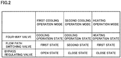
- Fig. 2 shows a relation between the operation mode of air conditioning apparatus 1 and each of the states of four-way valve 24, flow path switching valve 25, and bypass regulating valve 26.
- the operation mode includes: a first cooling operation mode, which is a cooling operation mode when the load is not low; a second cooling operation mode, which is a cooling operation mode when the load is low; and a heating operation mode.
- four-way valve 24 is controlled to be in the cooling operation state during each of the first cooling operation mode and the second cooling operation mode, and is controlled to be in the heating operation state during the heating operation mode.
- flow path switching valve 25 is controlled to be in the first state
- bypass regulating valve 26 is controlled to be in the open state.
- flow path switching valve 25 is controlled to be in the second state, and bypass regulating valve 26 is controlled to be in the close state.
- flow path switching valve 25 is controlled to be in the first state, and bypass regulating valve 26 is controlled to be in the close state.
- Fig. 3 shows main circuit 4 and bypass circuit 5 in the first cooling operation mode (cooling operation mode when the load is not low).
- main circuit 4 in the first cooling operation mode is a circuit in which the refrigerant circulates through compressor 20, pipe 43, pipe 44, outdoor heat exchanger 22, pipe 47 (extending through supercooling heat exchanger 23), liquid pipe 49, expansion valves 32, indoor heat exchangers 31, gas pipe 40, pipe 41, pipe 42, pipe 45, accumulator 21, and pipe 46 in this order.
- flow path switching valve 25 switches the flow path between indoor heat exchanger 31 and compressor 20 to the second flow path that does not extend through supercooling heat exchanger 23.
- the second flow path in the first cooling operation mode is a flow path that extends through gas pipe 40, pipe 41, pipe 42, pipe 45, accumulator 21, and pipe 46.
- bypass regulating valve 26 is controlled to be in the open state.
- bypass circuit 5 is constituted of pipe 50 and pipe 48. That is, in the first cooling operation mode, pipe 48 is included in bypass circuit 5. Accordingly, part of the refrigerant flowing in pipe 47 is branched from pipe 47, exchanges heat with the refrigerant flowing in pipe 47 through supercooling heat exchanger 23, and is joined to pipe 45 included in main circuit 4.
- compressor 20 suctions the refrigerant from pipe 46 and compresses the refrigerant.
- the compressed refrigerant flows into pipe 44 via pipe 43 and four-way valve 24.
- Outdoor heat exchanger 22 condenses the refrigerant flowing in pipe 44.
- Outdoor heat exchanger 22 is configured to exchange (dissipate) heat between outdoor air and the high-temperature high-pressure superheated vapor (refrigerant) discharged from compressor 20. With this heat exchange, the refrigerant is condensed and liquefied.
- the condensed refrigerant flows in pipe 47, exchanges heat, at supercooling heat exchanger 23, with the refrigerant flowing in pipe 48, and is supercooled.
- the refrigerant having flowed from pipe 47 into liquid main pipe 49a flows to be branched to the plurality of liquid branch pipes 49b.
- the inner diameter and surface area of liquid main pipe 49a are large. Further, depending on installation locations of indoor units 3, liquid main pipe 49a and liquid branch pipes 49b become long. Accordingly, the refrigerant flowing in liquid pipe 49 absorbs heat to some extent from the external air through liquid pipe 49. An amount of absorbed heat while the refrigerant flows in liquid pipe 49 is associated with the flow rate of the refrigerant in liquid pipe 49. As the flow rate of the refrigerant is higher, it takes a shorter time for the refrigerant to pass through liquid pipe 49, with the result that the amount of absorbed heat is decreased.
- Expansion valve 32 decompresses the refrigerant flowing in liquid branch pipe 49b.
- Indoor heat exchanger 31 evaporates the refrigerant having passed through expansion valve 32.
- Indoor heat exchanger 31 is configured such that the refrigerant decompressed by expansion valve 32 exchanges (absorbs) heat with the indoor air to evaporate.
- the evaporated refrigerant flows into outdoor unit 2 via gas pipe 40.
- the refrigerant having flowed into outdoor unit 2 reaches compressor 20 via pipe 41, flow path switching valve 25, pipe 42, four-way valve 24, pipe 45, accumulator 21 and pipe 46.
- supercooling heat exchanger 23 exchanges heat between the refrigerant flowing in pipe 47 and the refrigerant flowing in bypass circuit 5 branched from pipe 47, thereby supercooling the refrigerant flowing in pipe 47. Since the load is not low, the flow rate of the refrigerant in liquid pipe 49 is secured to some extent, thus resulting in a small amount of absorbed heat in the refrigerant flowing in liquid pipe 49. Accordingly, an amount of gas phase in the refrigerant at the inlet of expansion valve 32 is decreased, thereby suppressing a refrigerant sound generated from expansion valve 32.
- Fig. 4 shows main circuit 4 in the second cooling operation mode (cooling operation mode when the load is low).
- Fig. 4 shows a case where only one of the plurality of indoor units 3 is being operating.
- main circuit 4 in the second cooling operation mode is a circuit in which the refrigerant circulates through compressor 20, pipe 43, pipe 44, outdoor heat exchanger 22, pipe 47 (extending through supercooling heat exchanger 23), liquid pipe 49, expansion valve 32, indoor heat exchanger 31, gas pipe 40, pipe 41, pipe 48, pipe 45, accumulator 21, and pipe 46 in this order.
- flow path switching valve 25 switches the flow path between indoor heat exchanger 31 and compressor 20 to the third flow path that extends through supercooling heat exchanger 23 to exchange heat with pipe 47.
- the third flow path in the second cooling operation mode is a flow path that extends through gas pipe 40, pipe 41, pipe 48, pipe 45, accumulator 21, and pipe 46.
- pipe 48 is included in main circuit 4.
- the flow path from compressor 20 to pipe 47 in the second cooling operation mode is the same as the flow path shown in Fig. 3 from compressor 20 to pipe 47 in the first refrigerant operation mode. Hence, the flow path from compressor 20 to pipe 47 is not described in detail.
- bypass regulating valve 26 is controlled to be in the close state, a whole of the refrigerant supercooled by supercooling heat exchanger 23 flows into liquid main pipe 49a.
- expansion valves 32 of indoor units 3 that are not being operating are closed, the refrigerant flowing in liquid main pipe 49a passes through liquid branch pipe 49b corresponding to indoor unit 3 that is being operating, and is decompressed by expansion valve 32.
- Indoor heat exchanger 31 evaporates the refrigerant having passed through expansion valve 32. The evaporated refrigerant flows into outdoor unit 2 via gas pipe 40.
- the refrigerant having flowed into outdoor unit 2 flows into the accumulator via pipe 41, flow path switching valve 25, pipe 48 and pipe 45.
- Supercooling heat exchanger 23 exchanges heat between the high-temperature high-pressure refrigerant flowing in pipe 47 and the low-temperature low-pressure refrigerant flowing in pipe 48, thereby supercooling the refrigerant flowing in pipe 47.
- the flow rate of the refrigerant in main circuit 4 is small in the first place because the load is low. Accordingly, pressure loss in the flow path between indoor heat exchanger 31 and compressor 20 is suppressed from being increased.
- bypass regulating valve 26 Since bypass regulating valve 26 is controlled to be in the close state, the whole of the refrigerant flowing in pipe 47 flows in liquid pipe 49. Accordingly, the flow rate of the refrigerant in liquid pipe 49 can be avoided from being decreased extremely, whereby the amount of absorbed heat in the refrigerant passing through liquid pipe 49 can be suppressed from being increased. As a result, the amount of gas phase in the refrigerant at the inlet of expansion valve 32 is reduced, whereby a refrigerant sound generated from expansion valve 32 can be suppressed.
- the refrigerant having passed through gas pipe 40 absorbs heat in supercooling heat exchanger 23. Accordingly, even if the refrigerant flowing in gas pipe 40 is in a two-phase coexistence state, the refrigerant flowing in pipe 48 at the downstream side relative to supercooling heat exchanger 23 can be brought into the gas phase state. As a result, liquid back, which causes the liquid-phase refrigerant to flow into compressor 20, can be suppressed. Moreover, with the refrigerant at the outlet of indoor heat exchanger 31 being in the two-phase coexistence state, an uneven temperature distribution of indoor heat exchanger 31 can be reduced. As a result, dews resulting from the uneven temperature distribution in indoor heat exchanger 31 can be suppressed from falling down.
- Fig. 5 is a graph showing an enthalpy of the refrigerant just after passing through supercooling heat exchanger 23 in pipe 47 included in the first flow path during the cooling operation.
- the horizontal axis represents a ratio (hereinafter, referred to as "by-pass ratio") of the flow rate of the refrigerant passing through bypass regulating valve 26 with respect to the flow rate of the whole of the refrigerant in main circuit 4, and the vertical axis represents an enthalpy of the refrigerant just after passing through supercooling heat exchanger 23 in pipe 47.
- Fig. 6 is a graph showing the amount of absorbed heat when the refrigerant flows in liquid pipe 49 during the cooling operation.
- the horizontal axis represents the by-pass ratio and the vertical axis represents the amount of absorbed heat when the refrigerant flows in liquid pipe 49.
- Fig. 7 is a graph showing an enthalpy of the refrigerant at the inlet of expansion valve 32 during the cooling operation.
- the horizontal axis represents the by-pass ratio and the vertical axis represents the enthalpy of the refrigerant at the inlet of expansion valve 32.
- each of lines A, B represents a change of the enthalpy with respect to the by-pass ratio when flow path switching valve 25 is in the first state and bypass regulating valve 26 is in the open state.
- Line A represents a change of the enthalpy when the load is low
- line B represents a change of the enthalpy when the load is not low.
- Each of circles C, D represents the enthalpy when flow path switching valve 25 is in the second state and bypass regulating valve 26 is in the close state.
- Circle C represents the enthalpy when the load is low
- circle D represents the enthalpy when the load is not low.
- each of lines A, B represents a change of the amount of absorbed heat with respect to the by-pass ratio when flow path switching valve 25 is in the first state and bypass regulating valve 26 is in the open state.
- Line A represents a change of the amount of absorbed heat when the load is low
- line B represents a change of the amount of absorbed heat when the load is not low.
- Each of circles C, D represents the amount of absorbed heat when flow path switching valve 25 is in the second state and bypass regulating valve 26 is in the close state.
- Circle C represents the amount of absorbed heat when the load is low
- circle D represents the amount of absorbed heat when the load is not low.
- the enthalpy (line B and circle D) of the refrigerant just after passing through supercooling heat exchanger 23 in pipe 47 when the load is not low is smaller than the enthalpy (line A and circle C) of the refrigerant just after passing through supercooling heat exchanger 23 in pipe 47 when the load is low.
- This is due to the following reason: since the flow rate of the whole of the refrigerant in main circuit 4 when the load is not low is larger than the flow rate of the whole of the refrigerant therein when the load is low, the flow rate of the refrigerant in pipe 48 when the load is not low becomes more than the flow rate of the refrigerant in pipe 48 when the load is low.
- the inclination of line B is smaller than the inclination of line A.
- the inclination of each of lines A and B represents the inclination of an amount of increase in the amount of absorbed heat with respect to an amount of increase in the by-pass ratio.
- the enthalpy of the refrigerant at the inlet of expansion valve 32 is correlated with a total of the enthalpy of the refrigerant just after passing through supercooling heat exchanger 23 in pipe 47 and the amount of absorbed heat when the refrigerant flows in liquid pipe 49.
- a point a at which the by-pass ratio is 0 in line A represents a value when no refrigerant flows in pipe 48 extending through supercooling heat exchanger 23. That is, the refrigerant condensed by outdoor heat exchanger 22 is not supercooled by supercooling heat exchanger 23, and reaches expansion valve 32.
- the load is low, even if the refrigerant just after passing through supercooling heat exchanger 23 in pipe 47 is in the liquid phase, the refrigerant at the inlet of expansion valve 32 is in the two-phase state in which the gas phase and the liquid phase coexist, because the amount of absorbed heat when the refrigerant flows in liquid pipe 49 is large (see point a in Fig. 7 ).
- the enthalpy at circle C of Fig. 7 is smaller than the enthalpy at line A. This indicates that the refrigerant is in the liquid phase. This is due to the following reason: the amount of absorbed heat at circle C of Fig. 6 is the same as the amount of absorbed heat at point a, but the entropy at circle C of Fig. 5 is smaller than the enthalpy at point a of Fig. 5 . Therefore, when the load is low, in order to reduce introduction of the gas phase at the inlet of expansion valve 32 to suppress a refrigerant sound generated from expansion valve 32, flow path switching valve 25 is preferably controlled to be in the second state and bypass regulating valve 26 is preferably controlled to be in the close state.
- line B represents an enthalpy smaller than those at line A and circle C. This is due to the following reason: as shown in Fig. 6 , the amount of absorbed heat (line B) when the load is not low and the refrigerant flows in liquid pipe 49 is smaller than the amount of absorbed heat (line A) when the load is low and the refrigerant flows in liquid pipe 49. Moreover, the absolute value of the inclination of line B in Fig. 5 is more than the absolute value of the inclination of line B of Fig. 6 . Accordingly, when the load is not low, as indicated by line B of Fig.
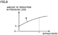
- Fig. 8 is a graph showing an amount of reduction of pressure loss in the flow path between indoor heat exchanger 31 and compressor 20 during the cooling operation when the load is not low.
- the horizontal axis represents the by-pass ratio
- the vertical axis represents the amount of reduction of the pressure loss from a reference.
- the reference of the amount of reduction of pressure loss which is represented by circle D, is pressure loss in the flow path between indoor heat exchanger 31 and compressor 20 when the load is not low and when flow path switching valve 25 is controlled to be in the second state and bypass regulating valve 26 is controlled to be in the close state.
- Line B represents a change in the amount of reduction of the pressure loss with respect to the by-pass ratio when the load is not low and when flow path switching valve 25 is controlled to be in the first state and bypass regulating valve 26 is controlled to be in the open state.
- flow path switching valve 25 is preferably controlled to be in the first state and bypass regulating valve 26 is preferably controlled to be in the open state in order to suppress pressure loss of the flow path between indoor heat exchanger 31 and compressor 20.
- the by-pass ratio is set such that the enthalpy (see line B of Fig. 7 ) at the inlet of expansion valve 32 and the amount of reduction of pressure loss (see line B of Fig. 8 ) fall within appropriate ranges.
- the by-pass ratio is set to a by-pass ratio r shown in each of Figs. 7 and 8 .
- Fig. 9 shows main circuit 4 and bypass circuit 5 in the heating operation mode.
- main circuit 4 in the heating operation mode is a circuit in which the refrigerant circulates through compressor 20, pipe 43, pipe 42, pipe 41, gas pipe 40, indoor heat exchangers 31, expansion valves 32, liquid pipe 49, pipe 47, outdoor heat exchanger 22, pipe 44, pipe 45, accumulator 21, and pipe 46 in this order.
- flow path switching valve 25 switches the flow path between indoor heat exchanger 31 and compressor 20 to the second flow path that does not extend through supercooling heat exchanger 23.
- the second flow path in the heating operation mode is a flow path that extends through pipe 43, pipe 42, pipe 41, and gas pipe 40.
- bypass regulating valve 26 is controlled to be in the close state as with the first cooling operation mode. In the heating operation mode, no heat exchange is performed in supercooling heat exchanger 23.
- compressor 20 suctions the refrigerant from pipe 46 and compresses the refrigerant.
- the compressed refrigerant flows into pipe 42 via pipe 43 and four-way valve 24. Since flow path switching valve 25 is controlled to be in the first state, the refrigerant flowing in pipe 42 reaches each of indoor heat exchangers 31 (condensers) via flow path switching valve 25, pipe 41, and gas pipe 40.
- Indoor heat exchanger 31 condenses the refrigerant.
- the refrigerant condensed by indoor heat exchanger 31 is decompressed by expansion valve 32, and flows into pipe 47 of outdoor unit 2 via liquid pipe 49.
- the flow rate of the refrigerant in main circuit 4 in the heating operation is smaller than that in the cooling operation and an excess of refrigerant is accumulated in accumulator 21. Accordingly, irrespective of a magnitude of the heating load, pressure loss in the flow path from compressor 20 to indoor heat exchanger 31 can be suppressed from being increased.
- indoor heat exchanger 31 functions as a condenser. Since a distance from the outlet (here, port P4) of indoor heat exchanger 31 to expansion valve 32 is short, the amount of absorbed heat in the refrigerant having passed along the distance can be ignored. Therefore, by exchanging heat in indoor heat exchanger 31 such that the refrigerant satisfies a certain degree of supercooling at port P4 of indoor heat exchanger 31, introduction of the gas phase at the inlet of expansion valve 32 can be reduced. As a result, a refrigerant sound generated from expansion valve 32 can be suppressed.
- controller 60 determines whether or not the load is low based on whether or not the number of indoor units 3 that is being operating among the plurality of indoor units 3 is larger than the reference value.
- controller 60 may employ another parameter correlated with the flow rate of the refrigerant in main circuit 4 to determine whether or not the cooling load is lower than a reference. For example, controller 60 may compare an operation frequency of compressor 20 with a reference value, may determine that the load is low when the operation frequency is smaller than the reference value, and may determine that the load is not low when the operation frequency is larger than the reference value.
- a differential pressure driving type four-way valve can be used as four-way valve 24.
- the differential pressure driving type four-way valve is configured to switch between the cooling operation state and the heating operation state based on a differential pressure between suction hole 20a and discharge hole 20b of compressor 20.
- the differential pressure driving type four-way valve includes: a main body in which a valve chamber is formed; a pair of pistons slidable in the valve chamber; and a valve body fixed between the pair of pistons.
- controller 60 controls flow path switching valve 25 to be brought into the second state and then into the first state. In other words, controller 60 controls flow path switching valve 25 to communicate pipe 41 with pipe 48 and then communicate pipe 41 with pipe 42.
- flow path switching valve 25 is in the second state, the refrigerant discharged by compressor 20 remains in pipe 43 and pipe 42.
- controller 60 may control expansion valve 32 and bypass regulating valve 26 to be in the close state while flow path switching valve 25 is controlled to be in the second state. Accordingly, the pressure at suction hole 20a of compressor 20 is decreased, whereby the differential pressure between suction hole 20a and discharge hole 20b of compressor 20 can be further increased.
- Flow path switching valve 25 may be constituted of two open/close valves. In this case, one open/close valve is disposed between pipe 41 and pipe 42, and the other open/close valve is disposed between pipe 41 and pipe 48. Accordingly, cost can be reduced as compared with a case where flow path switching valve 25 is constituted of a three-way valve.
- the refrigerant flows from pipe 41 to pipe 48 only during the cooling operation when the load is low. Accordingly, a valve having a smaller diameter than that of the open/close valve disposed between pipe 41 and pipe 42 is applicable to the open/close valve disposed between pipe 41 and pipe 48. As a result, cost for flow path switching valve 25 can be further reduced.
- the branch point of pipe 47 to which pipe 50 is connected is located between supercooling heat exchanger 23 and liquid pipe 49.
- the branch point of pipe 47 to which pipe 50 is connected may be located between outdoor heat exchanger 22 and supercooling heat exchanger 23.
- Fig. 1 shows an embodiment in which the number of indoor units 3 is 4, the number of indoor units 3 is not limited.
- the number of the indoor units may be 1 to 3, or may be 5 or more.
- an air conditioning apparatus 1 includes: an outdoor unit 2 including a compressor 20 and an outdoor heat exchanger 22; at least one indoor unit 3 including an expansion valve 32 and an indoor heat exchanger 31; and a main circuit 4 configured to circulate refrigerant through compressor 20, outdoor heat exchanger 22, expansion valve 32, and indoor heat exchanger 31.
- Main circuit 4 includes a first flow path between outdoor heat exchanger 22 and expansion valve 32.
- Air conditioning apparatus 1 further includes a supercooling heat exchanger 23 configured to supercool the refrigerant flowing in the first flow path.
- main circuit 4 includes a second flow path that does not extend through supercooling heat exchanger 23, and a third flow path that extends through supercooling heat exchanger 23.
- Air conditioning apparatus 1 further includes a flow path switching valve 25, a bypass circuit 5, a bypass regulating valve 26, and a controller 60.
- Flow path switching valve 25 is configured to switch, to one of the second flow path and the third flow path, the flow path between indoor heat exchanger 31 and compressor 20.
- Bypass circuit 5 is branched from the first flow path, extends through supercooling heat exchanger 23, and is joined to main circuit 4.
- Bypass regulating valve 26 is provided in bypass circuit 5.
- the controller is configured to control flow path switching valve 25 and bypass regulating valve 26.
- controller 60 In a cooling operation, when a parameter correlated with a flow rate of the refrigerant in main circuit 4 indicates that the flow rate of the refrigerant is more than a reference value, controller 60 is configured to control flow path switching valve 25 to switch, to the second flow path, the flow path between indoor heat exchanger 31 and compressor 20, and open bypass regulating valve 26. In the cooling operation, when the parameter indicates that the flow rate of the refrigerant is less than the reference value, controller 60 is configured to control flow path switching valve 25 to switch, to the third flow path, the flow path between indoor heat exchanger 31 and compressor 20, and close bypass regulating valve 26.
- bypass regulating valve 26 since bypass regulating valve 26 is closed in the case where the load is low, the flow rate of the refrigerant in the first flow path can be suppressed from being too small. Accordingly, the amount of absorbed heat in the refrigerant between supercooling heat exchanger 23 and expansion valve 32 can be suppressed, whereby the amount of gas phase at the inlet of expansion valve 32 can be reduced. As a result, even when the load is low, a refrigerant sound generated from expansion valve 32 can be suppressed. Further, the control of air conditioning apparatus 1 become stable. It should be noted that since the flow rate of the refrigerant in main circuit 4 is small in the case where the load is low, the pressure loss in the flow path between indoor heat exchanger 31 and compressor 20 can be suppressed from being increased.
- the flow path between indoor heat exchanger 31 and compressor 20 is switched to the second flow path that does not extend through supercooling heat exchanger 23. Accordingly, the pressure loss in the flow path between indoor heat exchanger 31 and compressor 20 can be suppressed from being increased. As a result, the size of supercooling heat exchanger 23 does not need to be increased, and the cost for supercooling heat exchanger 23 can be reduced to be low. Furthermore, the efficiency of air conditioning apparatus 1 is improved. It should be noted that in the case where the load is not low, by opening bypass regulating valve 26, the refrigerant flowing in bypass circuit 5 exchanges heat with the refrigerant flowing in the first flow path, whereby the refrigerant flowing in the first flow path can be supercooled. Accordingly, the amount of gas phase at the inlet of expansion valve 32 can be reduced, and the refrigerant sound generated from expansion valve 32 can be suppressed.
- an air conditioning apparatus that can suppress increase of pressure loss between an indoor heat exchanger and a compressor and that can suppress generation of a refrigerant sound in an expansion valve. Further, such an effect is exhibited by simple components such as flow path switching valve 25, bypass regulating valve 26 and the pipes, whereby manufacturing cost of air conditioning apparatus 1 can be also suppressed from being increased.
- the parameter may be an operation frequency of compressor 20.
- air conditioning apparatus 1 may include a plurality of indoor units 3, and the parameter may be the number of indoor units 3 that are being operating among the plurality of indoor units 3.
- Compressor 20 is provided with a suction hole 20a configured to suction the refrigerant, and a discharge hole 20b configured to discharge the refrigerant.
- Main circuit 4 includes: a pipe (first pipe) 41 configured to communicate with indoor heat exchanger 31; a pipe (second pipe) 42 configured not to extend through supercooling heat exchanger 23; and a pipe (third pipe) 48 configured to extend through supercooling heat exchanger 23 and communicate with suction hole 20a.
- Outdoor unit 2 further includes a four-way valve 24 configured to communicate pipe 42 with suction hole 20a and communicate outdoor heat exchanger 22 with discharge hole 20b in the cooling operation, and configured to communicate pipe 42 with discharge hole 20b and communicate outdoor heat exchanger 22 with suction hole 20a in a heating operation.
- Flow path switching valve 25 is configured to communicate pipe 41 with one of pipe 42 and pipe 48 and close the other of pipe 42 and pipe 48.
- the second flow path is formed by communicating pipe 41 with pipe 42.
- the third flow path is formed by communicating pipe 41 with pipe 48.
- Controller 60 is configured to control flow path switching valve 25 to communicate pipe 41 with pipe 48 and then communicate pipe 41 with pipe 42, when switching from the cooling operation to the heating operation.
- pipe 41 when switching from the cooling operation to the heating operation, pipe 41 is temporarily communicated with pipe 48. On this occasion, pipe 42 is closed. Accordingly, the refrigerant compressed by compressor 20 remains in pipe 42. This leads to a large differential pressure between suction hole 20a and discharge hole 20b of compressor 20, whereby four-way valve 24 can be operated normally.
- 1 air conditioning apparatus; 2: outdoor unit; 3: indoor unit; 4: main circuit; 5: bypass circuit; 20: compressor; 20a: suction hole; 20b: discharge hole; 21: accumulator; 22: outdoor heat exchanger; 23: supercooling heat exchanger; 24: four-way valve; 25: flow path switching valve; 26: bypass regulating valve; 31: indoor heat exchanger; 32: expansion valve; 40: gas pipe; 40a: gas main pipe; 40b: gas branch pipe; 41 to 48, 50: pipe; 49: liquid pipe; 49a: liquid main pipe; 49b: liquid branch pipe; 60: controller.
Landscapes
- Engineering & Computer Science (AREA)
- Mechanical Engineering (AREA)
- General Engineering & Computer Science (AREA)
- Chemical & Material Sciences (AREA)
- Combustion & Propulsion (AREA)
- Physics & Mathematics (AREA)
- Thermal Sciences (AREA)
- Fluid Mechanics (AREA)
- Air Conditioning Control Device (AREA)
- Compression-Type Refrigeration Machines With Reversible Cycles (AREA)
Applications Claiming Priority (1)
| Application Number | Priority Date | Filing Date | Title |
|---|---|---|---|
| PCT/JP2017/032238 WO2019049255A1 (fr) | 2017-09-07 | 2017-09-07 | Dispositif de climatisation |
Publications (3)
| Publication Number | Publication Date |
|---|---|
| EP3680565A1 true EP3680565A1 (fr) | 2020-07-15 |
| EP3680565A4 EP3680565A4 (fr) | 2020-09-30 |
| EP3680565B1 EP3680565B1 (fr) | 2021-11-10 |
Family
ID=65633689
Family Applications (1)
| Application Number | Title | Priority Date | Filing Date |
|---|---|---|---|
| EP17923991.8A Active EP3680565B1 (fr) | 2017-09-07 | 2017-09-07 | Dispositif de climatisation |
Country Status (6)
| Country | Link |
|---|---|
| US (1) | US11112140B2 (fr) |
| EP (1) | EP3680565B1 (fr) |
| JP (1) | JP6847239B2 (fr) |
| CN (1) | CN111051793B (fr) |
| ES (1) | ES2900352T3 (fr) |
| WO (1) | WO2019049255A1 (fr) |
Families Citing this family (5)
| Publication number | Priority date | Publication date | Assignee | Title |
|---|---|---|---|---|
| WO2019069666A1 (fr) * | 2017-10-02 | 2019-04-11 | カルソニックカンセイ株式会社 | Dispositif de climatisation |
| JP7258616B2 (ja) * | 2019-03-22 | 2023-04-17 | 三菱重工サーマルシステムズ株式会社 | チラーユニット |
| JP7258618B2 (ja) * | 2019-03-25 | 2023-04-17 | 三菱重工サーマルシステムズ株式会社 | チラーユニット |
| EP3879207B1 (fr) * | 2020-03-10 | 2023-09-06 | Trane International Inc. | Appareils de réfrigération et procédé pour leur opération |
| JP7216309B2 (ja) * | 2021-05-07 | 2023-02-01 | ダイキン工業株式会社 | 空気調和装置 |
Family Cites Families (26)
| Publication number | Priority date | Publication date | Assignee | Title |
|---|---|---|---|---|
| JPH0833225B2 (ja) | 1989-08-28 | 1996-03-29 | 三菱電機株式会社 | 多室用空気調和機 |
| JPH1068553A (ja) | 1996-08-27 | 1998-03-10 | Daikin Ind Ltd | 空気調和機 |
| JP2001317832A (ja) | 2000-05-10 | 2001-11-16 | Daikin Ind Ltd | 空気調和装置 |
| JP2002349979A (ja) * | 2001-05-31 | 2002-12-04 | Hitachi Air Conditioning System Co Ltd | 二酸化炭素ガス圧縮システム |
| JP4731806B2 (ja) * | 2003-12-01 | 2011-07-27 | パナソニック株式会社 | 冷凍サイクル装置およびその制御方法 |
| JP4459776B2 (ja) * | 2004-10-18 | 2010-04-28 | 三菱電機株式会社 | ヒートポンプ装置及びヒートポンプ装置の室外機 |
| US20060096308A1 (en) * | 2004-11-09 | 2006-05-11 | Manole Dan M | Vapor compression system with defrost system |
| US7114349B2 (en) * | 2004-12-10 | 2006-10-03 | Carrier Corporation | Refrigerant system with common economizer and liquid-suction heat exchanger |
| US7631510B2 (en) * | 2005-02-28 | 2009-12-15 | Thermal Analysis Partners, LLC. | Multi-stage refrigeration system including sub-cycle control characteristics |
| JP2006300373A (ja) * | 2005-04-18 | 2006-11-02 | Daikin Ind Ltd | 空気調和機 |
| JP2007139225A (ja) * | 2005-11-15 | 2007-06-07 | Hitachi Ltd | 冷凍装置 |
| JP2007155229A (ja) * | 2005-12-06 | 2007-06-21 | Sanden Corp | 蒸気圧縮式冷凍サイクル |
| JP4468888B2 (ja) * | 2005-12-16 | 2010-05-26 | 三星電子株式会社 | 空気調和装置 |
| US8887524B2 (en) * | 2006-03-29 | 2014-11-18 | Sanyo Electric Co., Ltd. | Refrigerating apparatus |
| JP4799347B2 (ja) * | 2006-09-28 | 2011-10-26 | 三菱電機株式会社 | 給湯、冷温水空気調和装置 |
| JP2009180406A (ja) * | 2008-01-30 | 2009-08-13 | Calsonic Kansei Corp | 超臨界冷凍サイクル |
| JP5120056B2 (ja) * | 2008-05-02 | 2013-01-16 | ダイキン工業株式会社 | 冷凍装置 |
| JP5071425B2 (ja) | 2009-03-30 | 2012-11-14 | 株式会社富士通ゼネラル | 分岐ユニット |
| JP2011133177A (ja) * | 2009-12-25 | 2011-07-07 | Fujitsu General Ltd | 空気調和機 |
| EP2489774B1 (fr) * | 2011-02-18 | 2015-06-17 | Electrolux Home Products Corporation N.V. | Sèche-linge à pompe à chaleur |
| ES2748573T3 (es) * | 2011-11-29 | 2020-03-17 | Mitsubishi Electric Corp | Dispositivo de refrigeración/acondicionamiento de aire |
| EP2889559B1 (fr) * | 2012-08-03 | 2018-05-23 | Mitsubishi Electric Corporation | Dispositif de climatisation |
| JP2014105890A (ja) | 2012-11-26 | 2014-06-09 | Panasonic Corp | 冷凍サイクル装置及びそれを備えた温水生成装置 |
| CN105042943A (zh) * | 2015-09-01 | 2015-11-11 | 中国科学院广州能源研究所 | 一种中低温热源热泵蒸汽系统 |
| GB2563162B (en) * | 2016-03-23 | 2020-10-21 | Mitsubishi Electric Corp | Air conditioner |
| CN106196430A (zh) * | 2016-06-30 | 2016-12-07 | 珠海格力电器股份有限公司 | 定频空调自动调整制冷量的系统及方法 |
-
2017
- 2017-09-07 CN CN201780094386.9A patent/CN111051793B/zh active Active
- 2017-09-07 EP EP17923991.8A patent/EP3680565B1/fr active Active
- 2017-09-07 ES ES17923991T patent/ES2900352T3/es active Active
- 2017-09-07 JP JP2019540196A patent/JP6847239B2/ja active Active
- 2017-09-07 US US16/639,651 patent/US11112140B2/en active Active
- 2017-09-07 WO PCT/JP2017/032238 patent/WO2019049255A1/fr unknown
Also Published As
| Publication number | Publication date |
|---|---|
| ES2900352T3 (es) | 2022-03-16 |
| US20200173682A1 (en) | 2020-06-04 |
| US11112140B2 (en) | 2021-09-07 |
| CN111051793B (zh) | 2022-03-29 |
| WO2019049255A1 (fr) | 2019-03-14 |
| JP6847239B2 (ja) | 2021-03-24 |
| EP3680565A4 (fr) | 2020-09-30 |
| EP3680565B1 (fr) | 2021-11-10 |
| CN111051793A (zh) | 2020-04-21 |
| JPWO2019049255A1 (ja) | 2020-10-01 |
Similar Documents
| Publication | Publication Date | Title |
|---|---|---|
| US11112140B2 (en) | Air conditioning apparatus | |
| US9068766B2 (en) | Air-conditioning and hot water supply combination system | |
| US8863545B2 (en) | Refrigeration apparatus | |
| EP2375188B1 (fr) | Climatiseur | |
| WO2009150761A1 (fr) | Dispositif à cycle frigorifique et procédé de régulation associé | |
| US6883346B2 (en) | Freezer | |
| US11384965B2 (en) | Refrigeration cycle apparatus performing a refrigerant circulation operation using a liquid pump | |
| JP2010133606A (ja) | エジェクタ式冷凍サイクル | |
| JP2007263440A (ja) | 空気調和装置 | |
| JP5359231B2 (ja) | エジェクタ式冷凍サイクル | |
| US11022354B2 (en) | Air conditioner | |
| JP2007240025A (ja) | 冷凍装置 | |
| EP3483523A1 (fr) | Appareil de cycle de réfrigération et appareil de climatisation équipé de celui-ci | |
| EP2770276A1 (fr) | Pompe à chaleur | |
| WO2014118953A1 (fr) | Dispositif à cycle frigorifique et procédé de contrôle du dispositif à cycle frigorifique | |
| JP2008267653A (ja) | 冷凍装置 | |
| JP5895662B2 (ja) | 冷凍装置 | |
| JP2009293887A (ja) | 冷凍装置 | |
| JPH10176869A (ja) | 冷凍サイクル装置 | |
| JP4023386B2 (ja) | 冷凍装置 | |
| WO2020148826A1 (fr) | Climatiseur | |
| JP2006125738A (ja) | 冷凍装置 | |
| JP2014126324A (ja) | 冷凍装置 | |
| JP2014070835A (ja) | 冷凍装置 | |
| JP5790367B2 (ja) | 冷凍装置 |
Legal Events
| Date | Code | Title | Description |
|---|---|---|---|
| STAA | Information on the status of an ep patent application or granted ep patent |
Free format text: STATUS: THE INTERNATIONAL PUBLICATION HAS BEEN MADE |
|
| PUAI | Public reference made under article 153(3) epc to a published international application that has entered the european phase |
Free format text: ORIGINAL CODE: 0009012 |
|
| STAA | Information on the status of an ep patent application or granted ep patent |
Free format text: STATUS: REQUEST FOR EXAMINATION WAS MADE |
|
| 17P | Request for examination filed |
Effective date: 20200224 |
|
| AK | Designated contracting states |
Kind code of ref document: A1 Designated state(s): AL AT BE BG CH CY CZ DE DK EE ES FI FR GB GR HR HU IE IS IT LI LT LU LV MC MK MT NL NO PL PT RO RS SE SI SK SM TR |
|
| AX | Request for extension of the european patent |
Extension state: BA ME |
|
| A4 | Supplementary search report drawn up and despatched |
Effective date: 20200901 |
|
| RIC1 | Information provided on ipc code assigned before grant |
Ipc: F24F 11/49 20180101ALI20200826BHEP Ipc: F25B 40/06 20060101ALI20200826BHEP Ipc: F25B 41/00 20060101ALI20200826BHEP Ipc: F24F 11/84 20180101ALI20200826BHEP Ipc: F24F 11/30 20180101AFI20200826BHEP Ipc: F24F 11/86 20180101ALI20200826BHEP Ipc: F25B 13/00 20060101ALI20200826BHEP Ipc: F25B 49/02 20060101ALI20200826BHEP Ipc: F25B 40/02 20060101ALI20200826BHEP |
|
| DAV | Request for validation of the european patent (deleted) | ||
| DAX | Request for extension of the european patent (deleted) | ||
| GRAP | Despatch of communication of intention to grant a patent |
Free format text: ORIGINAL CODE: EPIDOSNIGR1 |
|
| STAA | Information on the status of an ep patent application or granted ep patent |
Free format text: STATUS: GRANT OF PATENT IS INTENDED |
|
| RIC1 | Information provided on ipc code assigned before grant |
Ipc: F24F 11/30 20180101AFI20210430BHEP Ipc: F25B 13/00 20060101ALI20210430BHEP Ipc: F25B 40/02 20060101ALI20210430BHEP Ipc: F25B 41/00 20210101ALI20210430BHEP Ipc: F25B 49/02 20060101ALI20210430BHEP Ipc: F25B 40/06 20060101ALI20210430BHEP Ipc: F24F 11/49 20180101ALI20210430BHEP Ipc: F24F 11/84 20180101ALI20210430BHEP Ipc: F24F 11/86 20180101ALI20210430BHEP Ipc: F25B 41/40 20210101ALI20210430BHEP |
|
| INTG | Intention to grant announced |
Effective date: 20210528 |
|
| RAP3 | Party data changed (applicant data changed or rights of an application transferred) |
Owner name: MITSUBISHI ELECTRIC CORPORATION |
|
| GRAS | Grant fee paid |
Free format text: ORIGINAL CODE: EPIDOSNIGR3 |
|
| GRAA | (expected) grant |
Free format text: ORIGINAL CODE: 0009210 |
|
| STAA | Information on the status of an ep patent application or granted ep patent |
Free format text: STATUS: THE PATENT HAS BEEN GRANTED |
|
| AK | Designated contracting states |
Kind code of ref document: B1 Designated state(s): AL AT BE BG CH CY CZ DE DK EE ES FI FR GB GR HR HU IE IS IT LI LT LU LV MC MK MT NL NO PL PT RO RS SE SI SK SM TR |
|
| REG | Reference to a national code |
Ref country code: GB Ref legal event code: FG4D |
|
| REG | Reference to a national code |
Ref country code: AT Ref legal event code: REF Ref document number: 1446433 Country of ref document: AT Kind code of ref document: T Effective date: 20211115 Ref country code: CH Ref legal event code: EP |
|
| REG | Reference to a national code |
Ref country code: DE Ref legal event code: R096 Ref document number: 602017049298 Country of ref document: DE |
|
| REG | Reference to a national code |
Ref country code: IE Ref legal event code: FG4D |
|
| REG | Reference to a national code |
Ref country code: SE Ref legal event code: TRGR |
|
| REG | Reference to a national code |
Ref country code: LT Ref legal event code: MG9D |
|
| REG | Reference to a national code |
Ref country code: NL Ref legal event code: MP Effective date: 20211110 Ref country code: ES Ref legal event code: FG2A Ref document number: 2900352 Country of ref document: ES Kind code of ref document: T3 Effective date: 20220316 |
|
| REG | Reference to a national code |
Ref country code: AT Ref legal event code: MK05 Ref document number: 1446433 Country of ref document: AT Kind code of ref document: T Effective date: 20211110 |
|
| PG25 | Lapsed in a contracting state [announced via postgrant information from national office to epo] |
Ref country code: RS Free format text: LAPSE BECAUSE OF FAILURE TO SUBMIT A TRANSLATION OF THE DESCRIPTION OR TO PAY THE FEE WITHIN THE PRESCRIBED TIME-LIMIT Effective date: 20211110 Ref country code: LT Free format text: LAPSE BECAUSE OF FAILURE TO SUBMIT A TRANSLATION OF THE DESCRIPTION OR TO PAY THE FEE WITHIN THE PRESCRIBED TIME-LIMIT Effective date: 20211110 Ref country code: FI Free format text: LAPSE BECAUSE OF FAILURE TO SUBMIT A TRANSLATION OF THE DESCRIPTION OR TO PAY THE FEE WITHIN THE PRESCRIBED TIME-LIMIT Effective date: 20211110 Ref country code: BG Free format text: LAPSE BECAUSE OF FAILURE TO SUBMIT A TRANSLATION OF THE DESCRIPTION OR TO PAY THE FEE WITHIN THE PRESCRIBED TIME-LIMIT Effective date: 20220210 Ref country code: AT Free format text: LAPSE BECAUSE OF FAILURE TO SUBMIT A TRANSLATION OF THE DESCRIPTION OR TO PAY THE FEE WITHIN THE PRESCRIBED TIME-LIMIT Effective date: 20211110 |
|
| PG25 | Lapsed in a contracting state [announced via postgrant information from national office to epo] |
Ref country code: IS Free format text: LAPSE BECAUSE OF FAILURE TO SUBMIT A TRANSLATION OF THE DESCRIPTION OR TO PAY THE FEE WITHIN THE PRESCRIBED TIME-LIMIT Effective date: 20220310 Ref country code: PT Free format text: LAPSE BECAUSE OF FAILURE TO SUBMIT A TRANSLATION OF THE DESCRIPTION OR TO PAY THE FEE WITHIN THE PRESCRIBED TIME-LIMIT Effective date: 20220310 Ref country code: PL Free format text: LAPSE BECAUSE OF FAILURE TO SUBMIT A TRANSLATION OF THE DESCRIPTION OR TO PAY THE FEE WITHIN THE PRESCRIBED TIME-LIMIT Effective date: 20211110 Ref country code: NO Free format text: LAPSE BECAUSE OF FAILURE TO SUBMIT A TRANSLATION OF THE DESCRIPTION OR TO PAY THE FEE WITHIN THE PRESCRIBED TIME-LIMIT Effective date: 20220210 Ref country code: NL Free format text: LAPSE BECAUSE OF FAILURE TO SUBMIT A TRANSLATION OF THE DESCRIPTION OR TO PAY THE FEE WITHIN THE PRESCRIBED TIME-LIMIT Effective date: 20211110 Ref country code: LV Free format text: LAPSE BECAUSE OF FAILURE TO SUBMIT A TRANSLATION OF THE DESCRIPTION OR TO PAY THE FEE WITHIN THE PRESCRIBED TIME-LIMIT Effective date: 20211110 Ref country code: HR Free format text: LAPSE BECAUSE OF FAILURE TO SUBMIT A TRANSLATION OF THE DESCRIPTION OR TO PAY THE FEE WITHIN THE PRESCRIBED TIME-LIMIT Effective date: 20211110 Ref country code: GR Free format text: LAPSE BECAUSE OF FAILURE TO SUBMIT A TRANSLATION OF THE DESCRIPTION OR TO PAY THE FEE WITHIN THE PRESCRIBED TIME-LIMIT Effective date: 20220211 |
|
| PG25 | Lapsed in a contracting state [announced via postgrant information from national office to epo] |
Ref country code: SM Free format text: LAPSE BECAUSE OF FAILURE TO SUBMIT A TRANSLATION OF THE DESCRIPTION OR TO PAY THE FEE WITHIN THE PRESCRIBED TIME-LIMIT Effective date: 20211110 Ref country code: SK Free format text: LAPSE BECAUSE OF FAILURE TO SUBMIT A TRANSLATION OF THE DESCRIPTION OR TO PAY THE FEE WITHIN THE PRESCRIBED TIME-LIMIT Effective date: 20211110 Ref country code: RO Free format text: LAPSE BECAUSE OF FAILURE TO SUBMIT A TRANSLATION OF THE DESCRIPTION OR TO PAY THE FEE WITHIN THE PRESCRIBED TIME-LIMIT Effective date: 20211110 Ref country code: EE Free format text: LAPSE BECAUSE OF FAILURE TO SUBMIT A TRANSLATION OF THE DESCRIPTION OR TO PAY THE FEE WITHIN THE PRESCRIBED TIME-LIMIT Effective date: 20211110 Ref country code: DK Free format text: LAPSE BECAUSE OF FAILURE TO SUBMIT A TRANSLATION OF THE DESCRIPTION OR TO PAY THE FEE WITHIN THE PRESCRIBED TIME-LIMIT Effective date: 20211110 Ref country code: CZ Free format text: LAPSE BECAUSE OF FAILURE TO SUBMIT A TRANSLATION OF THE DESCRIPTION OR TO PAY THE FEE WITHIN THE PRESCRIBED TIME-LIMIT Effective date: 20211110 |
|
| REG | Reference to a national code |
Ref country code: DE Ref legal event code: R097 Ref document number: 602017049298 Country of ref document: DE |
|
| PLBE | No opposition filed within time limit |
Free format text: ORIGINAL CODE: 0009261 |
|
| STAA | Information on the status of an ep patent application or granted ep patent |
Free format text: STATUS: NO OPPOSITION FILED WITHIN TIME LIMIT |
|
| 26N | No opposition filed |
Effective date: 20220811 |
|
| PG25 | Lapsed in a contracting state [announced via postgrant information from national office to epo] |
Ref country code: AL Free format text: LAPSE BECAUSE OF FAILURE TO SUBMIT A TRANSLATION OF THE DESCRIPTION OR TO PAY THE FEE WITHIN THE PRESCRIBED TIME-LIMIT Effective date: 20211110 |
|
| PG25 | Lapsed in a contracting state [announced via postgrant information from national office to epo] |
Ref country code: SI Free format text: LAPSE BECAUSE OF FAILURE TO SUBMIT A TRANSLATION OF THE DESCRIPTION OR TO PAY THE FEE WITHIN THE PRESCRIBED TIME-LIMIT Effective date: 20211110 |
|
| PG25 | Lapsed in a contracting state [announced via postgrant information from national office to epo] |
Ref country code: MC Free format text: LAPSE BECAUSE OF FAILURE TO SUBMIT A TRANSLATION OF THE DESCRIPTION OR TO PAY THE FEE WITHIN THE PRESCRIBED TIME-LIMIT Effective date: 20211110 |
|
| REG | Reference to a national code |
Ref country code: CH Ref legal event code: PL |
|
| REG | Reference to a national code |
Ref country code: BE Ref legal event code: MM Effective date: 20220930 |
|
| P01 | Opt-out of the competence of the unified patent court (upc) registered |
Effective date: 20230512 |
|
| PG25 | Lapsed in a contracting state [announced via postgrant information from national office to epo] |
Ref country code: LU Free format text: LAPSE BECAUSE OF NON-PAYMENT OF DUE FEES Effective date: 20220907 |
|
| PG25 | Lapsed in a contracting state [announced via postgrant information from national office to epo] |
Ref country code: LI Free format text: LAPSE BECAUSE OF NON-PAYMENT OF DUE FEES Effective date: 20220930 Ref country code: IE Free format text: LAPSE BECAUSE OF NON-PAYMENT OF DUE FEES Effective date: 20220907 Ref country code: CH Free format text: LAPSE BECAUSE OF NON-PAYMENT OF DUE FEES Effective date: 20220930 |
|
| PG25 | Lapsed in a contracting state [announced via postgrant information from national office to epo] |
Ref country code: BE Free format text: LAPSE BECAUSE OF NON-PAYMENT OF DUE FEES Effective date: 20220930 |
|
| PGFP | Annual fee paid to national office [announced via postgrant information from national office to epo] |
Ref country code: TR Payment date: 20230906 Year of fee payment: 7 Ref country code: IT Payment date: 20230810 Year of fee payment: 7 Ref country code: GB Payment date: 20230727 Year of fee payment: 7 |
|
| PGFP | Annual fee paid to national office [announced via postgrant information from national office to epo] |
Ref country code: SE Payment date: 20230810 Year of fee payment: 7 Ref country code: FR Payment date: 20230808 Year of fee payment: 7 Ref country code: DE Payment date: 20230802 Year of fee payment: 7 |
|
| PGFP | Annual fee paid to national office [announced via postgrant information from national office to epo] |
Ref country code: ES Payment date: 20231003 Year of fee payment: 7 |
|
| REG | Reference to a national code |
Ref country code: DE Ref legal event code: R084 Ref document number: 602017049298 Country of ref document: DE |
|
| PG25 | Lapsed in a contracting state [announced via postgrant information from national office to epo] |
Ref country code: CY Free format text: LAPSE BECAUSE OF FAILURE TO SUBMIT A TRANSLATION OF THE DESCRIPTION OR TO PAY THE FEE WITHIN THE PRESCRIBED TIME-LIMIT Effective date: 20211110 |
|
| REG | Reference to a national code |
Ref country code: ES Ref legal event code: GC2A Effective date: 20240513 |
|
| PG25 | Lapsed in a contracting state [announced via postgrant information from national office to epo] |
Ref country code: MK Free format text: LAPSE BECAUSE OF FAILURE TO SUBMIT A TRANSLATION OF THE DESCRIPTION OR TO PAY THE FEE WITHIN THE PRESCRIBED TIME-LIMIT Effective date: 20211110 Ref country code: HU Free format text: LAPSE BECAUSE OF FAILURE TO SUBMIT A TRANSLATION OF THE DESCRIPTION OR TO PAY THE FEE WITHIN THE PRESCRIBED TIME-LIMIT; INVALID AB INITIO Effective date: 20170907 |
|
| PG25 | Lapsed in a contracting state [announced via postgrant information from national office to epo] |
Ref country code: MT Free format text: LAPSE BECAUSE OF FAILURE TO SUBMIT A TRANSLATION OF THE DESCRIPTION OR TO PAY THE FEE WITHIN THE PRESCRIBED TIME-LIMIT Effective date: 20211110 |