EP3680400B1 - Schaufel - Google Patents
Schaufel Download PDFInfo
- Publication number
- EP3680400B1 EP3680400B1 EP20160438.6A EP20160438A EP3680400B1 EP 3680400 B1 EP3680400 B1 EP 3680400B1 EP 20160438 A EP20160438 A EP 20160438A EP 3680400 B1 EP3680400 B1 EP 3680400B1
- Authority
- EP
- European Patent Office
- Prior art keywords
- shovel
- bucket
- recommended line
- excavation
- attachment
- Prior art date
- Legal status (The legal status is an assumption and is not a legal conclusion. Google has not performed a legal analysis and makes no representation as to the accuracy of the status listed.)
- Active
Links
- 238000009412 basement excavation Methods 0.000 description 80
- 239000002689 soil Substances 0.000 description 57
- 230000036544 posture Effects 0.000 description 20
- 238000001514 detection method Methods 0.000 description 18
- 238000004891 communication Methods 0.000 description 10
- 230000008878 coupling Effects 0.000 description 6
- 238000010168 coupling process Methods 0.000 description 6
- 238000005859 coupling reaction Methods 0.000 description 6
- 239000010720 hydraulic oil Substances 0.000 description 6
- 230000001133 acceleration Effects 0.000 description 4
- 230000007704 transition Effects 0.000 description 3
- 238000010586 diagram Methods 0.000 description 2
- 238000006073 displacement reaction Methods 0.000 description 2
- 238000000034 method Methods 0.000 description 2
- 230000008901 benefit Effects 0.000 description 1
- 230000005540 biological transmission Effects 0.000 description 1
- 230000008859 change Effects 0.000 description 1
- 230000000694 effects Effects 0.000 description 1
- 239000000446 fuel Substances 0.000 description 1
- 230000006870 function Effects 0.000 description 1
- 238000003384 imaging method Methods 0.000 description 1
- 230000007246 mechanism Effects 0.000 description 1
- 238000012986 modification Methods 0.000 description 1
- 230000004048 modification Effects 0.000 description 1
- 230000008569 process Effects 0.000 description 1
- 230000009897 systematic effect Effects 0.000 description 1
- 230000000007 visual effect Effects 0.000 description 1
Images


Classifications
-
- E—FIXED CONSTRUCTIONS
- E02—HYDRAULIC ENGINEERING; FOUNDATIONS; SOIL SHIFTING
- E02F—DREDGING; SOIL-SHIFTING
- E02F9/00—Component parts of dredgers or soil-shifting machines, not restricted to one of the kinds covered by groups E02F3/00 - E02F7/00
- E02F9/26—Indicating devices
- E02F9/261—Surveying the work-site to be treated
-
- E—FIXED CONSTRUCTIONS
- E02—HYDRAULIC ENGINEERING; FOUNDATIONS; SOIL SHIFTING
- E02F—DREDGING; SOIL-SHIFTING
- E02F9/00—Component parts of dredgers or soil-shifting machines, not restricted to one of the kinds covered by groups E02F3/00 - E02F7/00
- E02F9/20—Drives; Control devices
-
- E—FIXED CONSTRUCTIONS
- E02—HYDRAULIC ENGINEERING; FOUNDATIONS; SOIL SHIFTING
- E02F—DREDGING; SOIL-SHIFTING
- E02F9/00—Component parts of dredgers or soil-shifting machines, not restricted to one of the kinds covered by groups E02F3/00 - E02F7/00
- E02F9/26—Indicating devices
-
- E—FIXED CONSTRUCTIONS
- E02—HYDRAULIC ENGINEERING; FOUNDATIONS; SOIL SHIFTING
- E02F—DREDGING; SOIL-SHIFTING
- E02F9/00—Component parts of dredgers or soil-shifting machines, not restricted to one of the kinds covered by groups E02F3/00 - E02F7/00
- E02F9/26—Indicating devices
- E02F9/264—Sensors and their calibration for indicating the position of the work tool
-
- E—FIXED CONSTRUCTIONS
- E02—HYDRAULIC ENGINEERING; FOUNDATIONS; SOIL SHIFTING
- E02F—DREDGING; SOIL-SHIFTING
- E02F9/00—Component parts of dredgers or soil-shifting machines, not restricted to one of the kinds covered by groups E02F3/00 - E02F7/00
- E02F9/20—Drives; Control devices
- E02F9/2025—Particular purposes of control systems not otherwise provided for
- E02F9/2037—Coordinating the movements of the implement and of the frame
Definitions
- the present invention relates to a shovel.
- An operator of a shovel operates various operation levers to move an attachment and thereby performs work such as excavation to, for example, change the shape of a work object into a target shape.
- work such as excavation to, for example, change the shape of a work object into a target shape.
- it is difficult for an operator to accurately excavate a work object into an exact target shape through visual observation.
- the display system displays a guide screen including a target surface line that is a line segment indicating a cross section of a target surface and based on positional information of a design surface indicating a target shape of a work object, an extension line obtained by extending the target surface line, and a position of the tip of a bucket (see, for example, Patent Document 1).
- the present invention is made in view of the above problems, and one object of the present invention is to provide a shovel that can improve work efficiency.
- a shovel includes a lower traveling body that runs, an upper rotating body that is rotatably mounted on the lower traveling body, an attachment attached to the upper rotating body, a controller configured to control the shovel, wherein the controller is configured to calculate a rotation angle of the upper rotating body such that one of right and left edges of a bucket included in the attachment is positioned on a target surface or a recommended line.
- An embodiment of the present invention provides a shovel that can improve work efficiency.
- FIG. 1 is a side view of a shovel according to an embodiment of the present invention.
- the shovel includes a lower traveling body 1 on which an upper rotating body 3 is mounted via a rotation mechanism 2.
- a boom 4 is attached to the upper rotating body 3.
- An arm 5 is attached to an end of the boom 4, and a bucket 6 is attached to an end of the arm 5.
- the boom 4, the arm 5, and the bucket 6 are hydraulically-driven by a boom cylinder 7, an arm cylinder 8, and a bucket cylinder 9, respectively.
- the boom 4, the arm 5, and the bucket 6 constitute an excavation attachment.
- the excavation attachment may be replaced with any other attachment such as a foundation-excavation attachment, a leveling attachment, or a dredging attachment.
- the upper rotating body 3 includes a cabin 10 and a power source such as an engine 11.
- a communication device M1, a positioning device M2, a posture detection device M3, and a front camera S1 are attached to the upper rotating body 3.
- the communication device M1 controls communications between the shovel and external devices.
- the communication device M1 controls radio communications between a GNSS (global navigation satellite system) positioning system and the shovel.
- GNSS global navigation satellite system
- the communication device M1 obtains topographical information of a work site once a day when shovel work is started.
- the GNSS positioning system employs, for example, a network RTK-GNSS positioning technique.
- the positioning device M2 measures the position and the orientation of the shovel.
- the positioning device M2 is a GNSS receiver including an electronic compass, and measures the latitude, the longitude, and the altitude of the current position of the shovel as well as the orientation of the shovel.
- the posture detection device M3 detects postures of attachment components such as the boom 4, the arm 5, and the bucket 6.
- the front camera S1 is an imaging device that captures an image of a scene in front of the shovel.
- the front camera S1 captures an image of the shape of a ground after being excavated by an attachment.
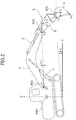
- FIG. 2 is a side view of the shovel of the present embodiment with examples of outputs of sensors constituting the posture detection device M3 provided in the shovel.
- the posture detection device M3 includes a boom angle sensor M3a, an arm angle sensor M3b, a bucket angle sensor M3c, and a body inclination sensor M3d.
- the boom angle sensor M3a obtains a boom angle ⁇ 1 and includes, for example, a rotation angle sensor for detecting a rotation angle of a boom foot pin, a stroke sensor for detecting the amount of stroke of the boom cylinder 7, and an inclination (acceleration) sensor for detecting an inclination angle of the boom 4.
- the boom angle ⁇ 1 is an angle between a line segment connecting a boom foot pin position P1 and an arm coupling pin position P2 and a horizontal line in an X-Z plane.
- the arm angle sensor M3b obtains an arm angle ⁇ 2 and includes, for example, a rotation angle sensor for detecting a rotation angle of an arm coupling pin, a stroke sensor for detecting the amount of stroke of the arm cylinder 8, and an inclination (acceleration) sensor for detecting an inclination angle of the arm 5.
- the arm angle ⁇ 2 is an angle between a line segment connecting the arm coupling pin position P2 and a bucket coupling pin position P3 and a horizontal line in the X-Z plane.
- the bucket angle sensor M3c obtains a bucket angle ⁇ 3 and includes, for example, a rotation angle sensor for detecting a rotation angle of a bucket coupling pin, a stroke sensor for detecting the amount of stroke of the bucket cylinder 9, and an inclination (acceleration) sensor for detecting an inclination angle of the bucket 6.
- the bucket angle ⁇ 3 is an angle between a line segment connecting the bucket coupling pin position P3 and a bucket tip position P4 and a horizontal line in the X-Z plane.
- the body inclination sensor M3d obtains an inclination angle ⁇ 4 of the shovel around the Y-axis and an inclination angle ⁇ 5 (not shown) of the shovel around the X-axis, and includes, for example, a biaxial inclination (acceleration) sensor.
- An X-Y plane in FIG. 2 is a horizontal plane.
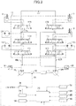
- FIG. 3 is a drawing illustrating an example of a configuration of a drive system provided in the shovel of the present embodiment.
- mechanical power transmission lines, high-pressure hydraulic lines, pilot lines, and electric control lines are represented by double lines, solid lines, dashed lines, and dotted lines, respectively.
- the drive system of the shovel includes an engine 11, main pumps 14L and 14R, a pilot pump 15, a control valve system 17, an operation device 26, an operation detection device 29, and a controller 30.
- the engine 11 is, for example, a diesel engine that is configured to maintain a predetermined engine speed.
- the output shaft of the engine 11 is connected to input shafts of the main pumps 14L and 14R and the pilot pump 15.
- the main pumps 14L and 14R supply hydraulic oil via the high-pressure hydraulic lines to the control valve system 17 and may be implemented by, for example, variable-displacement swash-plate hydraulic pumps.
- the discharge pressure of the main pumps 14L and 14R is detected by a discharge pressure sensor 18.
- the discharge pressure sensor 18 outputs the detected discharge pressure of the main pumps 14L and 14R to the controller 30.
- the pilot pump 15 supplies hydraulic oil via a pilot line 25 to hydraulic control devices including the operation device 26, and may be implemented by, for example, a fixed-displacement hydraulic pump.
- the control valve system 17 is a hydraulic control device that controls the hydraulic system of the shovel.
- the control valve system 17 includes flow control valves 171-176 that control the flow of hydraulic oil discharged from the main pumps 14L and 14R.
- the control valve system 17 selectively supply the hydraulic oil discharged from the main pumps 14L and 14R via the flow control valves 171-176 to one or more of the boom cylinder 7, the arm cylinder 8, the bucket cylinder 9, a traveling hydraulic motor 1A (left), a traveling hydraulic motor 1B (right), and a rotating hydraulic motor 2A.
- the boom cylinder 7, the arm cylinder 8, the bucket cylinder 9, the traveling hydraulic motor 1A (left), the traveling hydraulic motor 1B (right), and the rotating hydraulic motor 2A are collectively referred to as "hydraulic actuators".
- the operation device 26 is used by an operator to operate the hydraulic actuators.
- the operation device 26 supplies the hydraulic oil discharged from the pilot pump 15 via the pilot line 25 to pilot ports of the flow control valves corresponding to the hydraulic actuators.
- the pressure (pilot pressure) of the hydraulic oil supplied to each pilot port corresponds to the operation direction and the operation amount of a lever or a pedal (not shown) of the operation device 26 corresponding to one of the hydraulic actuators.
- the operation detection device 29 detects operations performed by the operator using the operation device 26.
- the operation detection device 29 detects pressures representing the operation directions and the operation amounts of levers and pedals of the operation device 26 corresponding to the hydraulic actuators, and outputs the detected pressures to the controller 30.
- Operations performed using the operation device 26 may also be obtained based on outputs of sensors such as a potentiometer other than the pressure sensors.
- the controller 30 is a control device for controlling the shovel and is implemented by, for example, a computer including a CPU, a RAM, and a nonvolatile memory.
- the controller 30 reads programs corresponding to various functional components from a ROM, loads the read programs into the RAM, and causes the CPU to perform processes corresponding to the functional components.
- the controller 30 is connected to the discharge pressure sensor 18, a display device 50, the communication device M1, the positioning device M2, the posture detection device M3, and the front camera S1.
- the controller 30 performs calculations based on various types of data input from the discharge pressure sensor 18, the communication device M1, the positioning device M2, the posture detection device M3, and the front camera S1, and outputs calculation results to the display device 50.
- the display device 50 is attached to, for example, a position in the cabin 10 where the operator can view a display screen, and displays the calculation results of the controller 30.
- the display device 50 may also be a wearable device integrated with, for example, a goggle worn by the operator. This improves the visibility of displayed information and enables the operator of the shovel to more efficiently carry out work.
- FIG. 4 is a functional block diagram illustrating an example of a configuration of the controller 30.
- the controller 30 includes a terrain database updater 31, a position coordinate updater 32, a ground shape obtainer 33, a soil property detector 34, and a recommended line calculator 35.
- the terrain database updater 31 is a functional component that updates a terrain database containing browsable and systematic terrain information of work sites.
- the terrain database updater 31 obtains terrain information of a work site via the communication device M1 and updates the terrain database when, for example, the shovel is started.
- the terrain database is stored in, for example, a nonvolatile memory. Terrain information of work sites is described, for example, in a three-dimensional terrain model based on a world geodetic system.
- the position coordinate updater 32 is a functional component that updates coordinates indicating the current position of the shovel and the orientation of the shovel.
- the position coordinate updater 32 obtains the positional coordinates and the orientation of the shovel in the world geodetic system based on an output of the positioning device M2, and updates coordinates indicating the current position of the shovel and data indicating the orientation of the shovel that are stored in, for example, a nonvolatile memory.
- the ground shape obtainer 33 is a functional component that obtains information regarding the current shape of a target ground on which work is to be performed.
- the ground shape obtainer 33 obtains an initial shape of a target ground before being excavated from the terrain information updated by the terrain database updater 31 based on the coordinates indicating the current position of the shovel and the orientation of the shovel that are updated by the position coordinate updater 32.
- the ground shape obtainer 33 calculates a current shape of the target ground after being excavated by the shovel based on the past transition of the posture of an attachment detected by the posture detection device M3.
- the ground shape obtainer 33 may also be configured to calculate the current shape of the target ground after being excavated by the shovel based on an image of the excavated target ground captured by the front camera S1. Further, the ground shape obtainer 33 may be configured to calculate the current shape of the excavated target ground based on both of the past transition of the posture of the attachment detected by the posture detection device M3 and image data of the excavated target ground captured by the front camera S1.
- the ground shape obtainer 33 obtains an initial shape of the target ground before being excavated by the shovel and calculates a current shape of the excavated target ground each time excavation is performed by the shovel. For example, the ground shape obtainer 33 calculates a current shape of the excavated target ground after each excavation cycle where the boom 4 descends and the arm 5 and the bucket 6 rotate to excavate the target ground and then the boom 4 ascends.
- the soil property detector 34 is a functional component that detects the soil property of the target ground.
- the soil property detector 34 detects the soil property of the target ground based on a discharge pressure of the main pumps 14L and 14R output from the discharge pressure sensor 18 during excavation.
- the soil property detector 34 determines whether the bucket 6 is in contact with the target ground and excavation is being performed based on the posture of the attachment detected by the posture detection device M3, and detects the soil property based on a discharge pressure output from the discharge pressure sensor 18.
- the main pumps 14L and 14R are controlled so that their output horsepower becomes low, and as a result the discharge pressure of the main pumps 14L and 14R becomes low.
- the soil property detector 34 determines that the target ground is sandy soil when the discharge pressure of the main pumps 14L and 14R detected by the discharge pressure sensor 18 during excavation is less than a predetermined threshold.
- the main pumps 14L and 14R are controlled so that their output horsepower becomes high, and as a result the discharge pressure of the main pumps 14L and 14R becomes high.
- the soil property detector 34 determines that the target ground is cohesive soil when the discharge pressure of the main pumps 14L and 14R detected by the discharge pressure sensor 18 during excavation is greater than or equal to the predetermined threshold.
- the soil property detector 34 may also be configured to detect, for example, gravelly soil in addition to sandy soil and cohesive soil based on a discharge pressure of the main pumps 14L and 14R detected by the discharge pressure sensor 18. Further, the soil property detector 34 may be configured to detect the soil property of a target ground based on one or more of a boom cylinder pressure, an arm cylinder pressure, and a bucket cylinder pressure detected during excavation.
- the recommended line calculator 35 is a functional component that calculates a recommended line suitable to excavate the target ground with a current shape that is obtained or calculated by the ground shape obtainer 33.
- the recommended line calculator 35 calculates a recommended line suitable to excavate the target ground with a current shape based on the capacity of the bucket 6 as an attachment and the soil property of the target ground detected by the soil property detector 34.
- the recommended line is represented by a trace of the tip of the bucket 6.
- the recommended line calculator 35 defines a recommended line by an excavation depth and an excavation length. For example, when the target ground is sandy soil, excavation work where the bucket 6 is inserted deep into the ground and rotated can be performed with low horsepower. For this reason, when the target ground is sandy soil, the recommended line calculator 35 calculates a recommended line such that the excavation depth becomes large and the excavation length becomes short. The excavation depth and the excavation length are obtained based on, for example, the capacity and the maximum load of the bucket 6.
- the recommended line calculator 35 calculates a recommended line such that the excavation depth becomes smaller and the excavation length becomes longer compared with a case where the target ground is sandy soil.
- the recommended line calculator 35 calculates a recommended line for the current shape of the excavated target ground.
- the ground shape obtainer 33 calculates a current shape of the excavated target ground.
- the recommended line calculator 35 calculates a recommended line suitable to excavate the target ground with the calculated current shape.
- the recommended line calculator 35 calculates an attachment posture such as an angle of the bucket 6 suitable to perform excavation along the calculated recommended line.
- the recommended line calculator 35 calculates an angle of the bucket 6 for performing excavation along the recommended line.
- the recommended line calculator 35 may be configured to also calculate angles of the boom 4 and the arm 5 suitable to perform excavation along the recommended line.
- the recommended line calculator 35 outputs, to the display device 50, the current shape of the target ground obtained or calculated by the ground shape obtainer 33, the recommended line for the current shape of the target ground, and the angle of the bucket 6 for performing excavation along the recommended line.
- the display device 50 displays, on a screen, the current shape of the target ground and the recommended line output from the recommended line calculator 35. Also, the display device 50 displays, on the screen, the current position of the attachment detected by the posture detection device M3 and the angle of the bucket 6 for performing excavation along the recommended line.
- FIG. 5 illustrates an example of an image 51 displayed by the display device 50.
- FIG. 5 illustrates an example of the image 51 that is displayed when sandy soil is excavated.
- a current bucket position 61 indicating the current position of the bucket 6 and a current shape 71 of the target ground are displayed by solid lines.
- the soil property detector 34 detects the soil property of the target ground and the recommended line calculator 35 calculates a recommended line.
- the recommended line calculator 35 also calculates an angle of the bucket 6 for performing excavation along the recommended line.
- a recommended line 72 for the current shape 71 of the target ground is displayed by a dashed line as illustrated in FIG. 5 .
- bucket excavation positions 62, 63, and 64 during excavation along the recommended line 72 are displayed by dashed lines as excavation positions of the attachment.
- the current bucket position 61 displayed in the image 51 changes along with the actual movement of the bucket 6.
- the operator While viewing the image 51 displayed on the display device 50, the operator operates the attachment such that the bucket 6 moves along the recommended line 72. Also, the operator rotates the bucket 6 to match the angles indicated by the bucket excavation positions 62, 63, and 64.
- the current shape 71 of the ground in the image 51 is updated to a shape of the excavated ground.
- the shape of the excavated ground is calculated by the ground shape obtainer 33 based on at least one of the past transition of the posture of the attachment detected by the posture detection device M3 and an image of the excavated ground captured by the front camera S1.
- the recommended line calculator 35 calculates a recommended line for the current shape of the excavated ground, and the recommended line 72 displayed in the image 51 is updated.
- the operator of the shovel can continue the excavation work while viewing the current shape 71 of the ground and the recommended line 72 that are displayed in the image 51 and updated each time excavation is performed with the attachment.
- the operator of the shovel can quickly and efficiently perform work by operating the attachment to excavate the target ground along a recommended line while viewing the image 51 displayed on the display device 50.
- FIG. 6 is a drawing illustrating an example of an image 51 displayed on the display device 50 when cohesive soil is excavated. If cohesive soil is excavated by inserting the bucket 6 deep into the ground and rotating the bucket 6 as in the case where sandy soil is excavated, high horsepower is necessary and energy efficiency is reduced. For this reason, when the soil property detector 34 detects that the target ground is cohesive soil, the recommended line calculator 35 calculates a recommended line such that an excavation depth D2 becomes smaller (D2 ⁇ D1) and an excavation length L2 becomes longer (L2 > L1) compared with the case ( FIG. 5 ) where the target ground is sandy soil.
- the target ground is cohesive soil
- the current shape 71 of the ground and the recommended line 72 displayed in the image 51 are updated.
- displaying a recommended line corresponding to the soil property of the target ground makes it possible to prevent the operator from inserting the bucket 6 deep into the ground more than necessary and reducing the fuel efficiency, and makes it possible to efficiently perform excavation work depending on the soil property of the target ground.
- a current shape of a target ground and a recommended line suitable for excavating the target ground are displayed on the display device 50 together with the current position of the bucket 6.
- the current shape of a ground is updated and a next recommended line is calculated and displayed each time an attachment is operated by an operator and excavation is performed.
- recommended lines for the multiple excavation cycles are calculated in advance and displayed simultaneously. This configuration enables an operator to easily determine how many excavation cycles need to be performed to reach the vicinity of the target surface.
- FIG. 7 is a drawing illustrating an example of an image displayed on a display device when sandy soil is excavated through multiple cycles. Similarly to FIG. 5 , in an image 51 of FIG. 7 , a current bucket position 61 indicating the current position of the bucket 6 and a current shape 71 of the target ground are displayed by solid lines.
- the soil property detector 34 detects the soil property of the target ground. Also, the recommended line calculator 35 calculates a first recommended line for a first excavation cycle. The recommended line calculator 35 also calculates an angle of the bucket 6 for performing excavation along the first recommended line.
- a first recommended line 72 for the current shape 71 of the target ground is displayed by a dashed line as illustrated in FIG. 7 .
- bucket excavation positions 62, 63, and 64 during excavation along the recommended line 72 are displayed by dashed lines as excavation positions of the attachment.
- the recommended line calculator 35 determines whether the calculated first recommended line 72 is included in a vicinity area 101 near the target surface 100.
- the vicinity area 101 is determined based on, for example, the excavation depth D2 per cycle.
- the recommended line calculator 35 calculates a second recommended line 73 for a second excavation cycle. After calculating the second recommended line 73, the recommended line calculator 35 determines whether the calculated second recommended line 73 is included in the vicinity area 101 near the target surface 100.
- the recommended line calculator 35 When the calculated second recommended line 73 is not included in the vicinity area 101, the recommended line calculator 35 further calculates a third recommended line 74 for a third excavation cycle. After calculating the third recommended line 74, the recommended line calculator 35 determines whether the calculated third recommended line 74 is included in the vicinity area 101 near the target surface 100.
- the recommended line calculator 35 displays the second and third recommended lines 73 and 74 by dashed lines in addition to the first recommended line 72.
- an operator can easily determine the number of excavation cycles that need to be performed to reach the vicinity of the target surface by viewing displayed recommended lines before starting excavation.
- the recommended line calculator 35 may also display the target surface 100 and the vicinity area 101. Further, the recommended line calculator 35 may display the number of excavation cycles.
- a recommended line is calculated based on a soil property.
- parameters used to calculate recommended lines are not limited to soil properties, and recommended lines may be calculated based also on parameters other than soil properties.
- the size, shape, and position of a buried object are taken into account in calculating a recommended line in addition to a soil property.
- FIG. 8 is a drawing illustrating an example of an image displayed on a display device when sandy soil is excavated taking into account a buried object. Similarly to FIG. 5 , in an image 51 of FIG. 8 , a current bucket position 61 indicating the current position of the bucket 6 and a current shape 71 of the target ground are displayed by solid lines.
- the soil property detector 34 detects the soil property of the target ground.
- the recommended line calculator 35 calculates a recommended line based on the soil property such that the recommended line does not interfere with the buried object.
- a recommended line 82 in FIG. 8 is calculated by the recommended line calculator 35 based on the size, shape, and position of the buried object and the detected soil property.
- FIG. 8 also illustrates a recommended line 72 that is calculated without taking into account the size, shape, and position of the buried object.
- the recommended line 72 calculated without taking into account the size, shape, and position of the buried object interferes with a buried object 90.
- the recommended line 82 calculated taking into account the size, shape, and position of the buried object does not interfere with the buried object 90.
- the third embodiment makes it possible to calculate and display a recommended line that does not interfere with an underground buried object.
- the recommended line calculator 35 may be configured to generate an image of the buried object 90 based on the pre-registered size, shape, and position of the buried object 90, and display the generated image in the image 51.
- the position of the tip of the bucket 6 in a side view of excavation work is displayed as a recommended line together with bucket excavation positions.
- the position of the tip of the bucket 6 in a top view of excavation work is displayed as a recommended line together with bucket excavation positions and rotation directions (rotation angles) of the upper rotating body 3..
- the operator rotates the upper rotating body 3 in each cycle so that a blade edge of the bucket 6 is positioned on a predetermined line.
- the recommended line calculator 35 of the present embodiment displays a top view image of excavation work such as grid excavation.
- the displayed image includes a recommended line indicating the position of a blade edge of the bucket 6, and bucket excavation positions and rotation directions (and rotation angles) of the upper rotating body 3 for respective cycles.
- FIG. 9 is a drawing illustrating an example of a top view image of excavation work.
- An image 51 in FIG. 9 includes a recommended line 72 indicating the position of the blade edge of the bucket 6.
- a current bucket position 61 indicating the current position of the bucket 6 and a rotation direction 201 of the current bucket position 61 around a rotation center 300 with respect to a reference direction 200 are displayed by solid lines.
- a rotation angle of the current bucket position 61 with respect to the reference direction 200 may be displayed.
- bucket excavation positions 62, 63, and 64 during excavation along the recommended line 72 in respective cycles are displayed by dotted lines.
- rotation directions 202-204 of the bucket excavation positions 62, 63, and 64 around the rotation center 300 with respect to the reference direction 200 are displayed by dotted lines.
- Rotation angles of the bucket excavation positions 62, 63, and 64 with respect to the reference direction 200 may also be displayed.
Landscapes
- Engineering & Computer Science (AREA)
- Mining & Mineral Resources (AREA)
- Civil Engineering (AREA)
- General Engineering & Computer Science (AREA)
- Structural Engineering (AREA)
- Component Parts Of Construction Machinery (AREA)
- Operation Control Of Excavators (AREA)
Claims (5)
- Bagger, umfassend:einen unteren Fahrkörper (1), der fährt;einen oberen Drehkörper (3), der drehbar auf dem unteren Fahrkörper (1) angebracht ist;ein Ansatzstück, das an dem oberen Drehkörper (3) angebracht ist;gekennzeichnet durcheine Steuerung (30), die konfiguriert ist, den Bagger zu steuern,wobei die Steuerung (30) konfiguriert ist, einen Drehwinkel des oberen Drehkörpers (3) derart zu berechnen, dass ein rechter oder linker Rand einer Schaufel (6), welche in dem Ansatzstück enthalten ist, auf einer Zielfläche (100) oder einer empfohlenen Linie (72, 73, 74, 82) positioniert ist.
- Bagger nach Anspruch 1, ferner umfassend: eine Anzeigevorrichtung (50), die konfiguriert ist, ein Bild einer Draufsicht des Ansatzstücks anzuzeigen.
- Bagger nach Anspruch 2, wobei jedes Mal, wenn ein Zielboden mit dem Ansatzstück ausgehoben wird, die Anzeigevorrichtung (50) konfiguriert ist, die empfohlene Linie (72, 73, 74, 82), die von der Steuerung (30) basierend auf einer Form des ausgehobenen Zielbodens berechnet wird, zu aktualisieren und anzuzeigen.
- Bagger nach Anspruch 3, wobei die Steuerung (30) konfiguriert ist, die empfohlene Linie (72, 73, 74, 82) für die Form des Zielbodens zu berechnen, der mit dem Ansatzstück ausgehoben wird.
- Bagger nach einem der Ansprüche 2 bis 4, wobei die Anzeigevorrichtung (50) konfiguriert ist, zusätzlich zu dem Bild der Draufsicht des Ansatzstücks ein Bild einer Seitenansicht des Ansatzstücks anzuzeigen.
Applications Claiming Priority (3)
| Application Number | Priority Date | Filing Date | Title |
|---|---|---|---|
| JP2015256681 | 2015-12-28 | ||
| EP16881784.9A EP3399111B1 (de) | 2015-12-28 | 2016-12-27 | Schaufel |
| PCT/JP2016/088954 WO2017115810A1 (ja) | 2015-12-28 | 2016-12-27 | ショベル |
Related Parent Applications (2)
| Application Number | Title | Priority Date | Filing Date |
|---|---|---|---|
| EP16881784.9A Division EP3399111B1 (de) | 2015-12-28 | 2016-12-27 | Schaufel |
| EP16881784.9A Division-Into EP3399111B1 (de) | 2015-12-28 | 2016-12-27 | Schaufel |
Publications (2)
| Publication Number | Publication Date |
|---|---|
| EP3680400A1 EP3680400A1 (de) | 2020-07-15 |
| EP3680400B1 true EP3680400B1 (de) | 2021-09-22 |
Family
ID=59224908
Family Applications (2)
| Application Number | Title | Priority Date | Filing Date |
|---|---|---|---|
| EP16881784.9A Active EP3399111B1 (de) | 2015-12-28 | 2016-12-27 | Schaufel |
| EP20160438.6A Active EP3680400B1 (de) | 2015-12-28 | 2016-12-27 | Schaufel |
Family Applications Before (1)
| Application Number | Title | Priority Date | Filing Date |
|---|---|---|---|
| EP16881784.9A Active EP3399111B1 (de) | 2015-12-28 | 2016-12-27 | Schaufel |
Country Status (6)
| Country | Link |
|---|---|
| US (2) | US11230823B2 (de) |
| EP (2) | EP3399111B1 (de) |
| JP (1) | JP6611205B2 (de) |
| KR (1) | KR102570490B1 (de) |
| CN (2) | CN108431338B (de) |
| WO (1) | WO2017115810A1 (de) |
Families Citing this family (16)
| Publication number | Priority date | Publication date | Assignee | Title |
|---|---|---|---|---|
| US20200217050A1 (en) | 2017-09-06 | 2020-07-09 | Hitachi Construction Machinery Co., Ltd. | Work machine |
| JP7379156B2 (ja) * | 2017-09-08 | 2023-11-14 | 住友重機械工業株式会社 | ショベル |
| JPWO2019112059A1 (ja) * | 2017-12-07 | 2020-11-26 | 住友建機株式会社 | ショベル |
| JP7155516B2 (ja) * | 2017-12-20 | 2022-10-19 | コベルコ建機株式会社 | 建設機械 |
| JPWO2019131980A1 (ja) * | 2017-12-27 | 2020-12-17 | 住友建機株式会社 | ショベル |
| KR102613270B1 (ko) | 2017-12-27 | 2023-12-12 | 스미토모 겐키 가부시키가이샤 | 쇼벨 |
| JP6962841B2 (ja) * | 2018-03-22 | 2021-11-05 | ヤンマーパワーテクノロジー株式会社 | 旋回作業車の表示システム |
| JP6841784B2 (ja) * | 2018-03-28 | 2021-03-10 | 日立建機株式会社 | 作業機械 |
| JP7000957B2 (ja) | 2018-03-29 | 2022-01-19 | コベルコ建機株式会社 | 作業機械操縦装置 |
| JP7088792B2 (ja) * | 2018-09-12 | 2022-06-21 | 株式会社小松製作所 | 作業機械、制御装置、および制御方法 |
| CN109801366A (zh) | 2019-01-25 | 2019-05-24 | 北京百度网讯科技有限公司 | 用于选取目标挖掘点的方法和装置 |
| DE102019207165A1 (de) * | 2019-05-16 | 2020-11-19 | Robert Bosch Gmbh | Verfahren zur Berechnung eines Aushubvolumens |
| JP2022168730A (ja) | 2021-04-26 | 2022-11-08 | コベルコ建機株式会社 | 目標軌跡生成システム |
| CN113482074B (zh) * | 2021-06-01 | 2022-09-30 | 北京市政建设集团有限责任公司 | 一种智能浅埋暗挖的液压驱动方法、装置、介质及设备 |
| KR20240023641A (ko) * | 2022-03-22 | 2024-02-22 | 히다찌 겐끼 가부시키가이샤 | 작업 기계 |
| WO2023190877A1 (ja) * | 2022-03-31 | 2023-10-05 | 住友重機械工業株式会社 | 支援装置、作業機械、プログラム |
Family Cites Families (44)
| Publication number | Priority date | Publication date | Assignee | Title |
|---|---|---|---|---|
| JPS5426742U (de) | 1977-07-27 | 1979-02-21 | ||
| JPS5555732A (en) * | 1978-10-19 | 1980-04-23 | Komatsu Ltd | Apparatus and method for controlling operation machine |
| JPS62185932A (ja) | 1986-02-13 | 1987-08-14 | Komatsu Ltd | 掘削機械の作業状態監視装置 |
| JPH0788674B2 (ja) * | 1987-02-04 | 1995-09-27 | 株式会社小松製作所 | パワ−シヨベルの作業機制御装置 |
| WO1993009300A1 (fr) * | 1991-10-29 | 1993-05-13 | Kabushiki Kaisha Komatsu Seisakusho | Procede pour selectionner le mode de fonctionnement automatique d'un engin de chantier |
| JP2966739B2 (ja) * | 1994-11-16 | 1999-10-25 | 新キャタピラー三菱株式会社 | 建設機械の作業機制御装置およびその制御方法 |
| JPH08333769A (ja) * | 1995-06-09 | 1996-12-17 | Shin Caterpillar Mitsubishi Ltd | 油圧ショベル |
| US5854988A (en) * | 1996-06-05 | 1998-12-29 | Topcon Laser Systems, Inc. | Method for controlling an excavator |
| JP2000291076A (ja) * | 1999-04-01 | 2000-10-17 | Tokai Rika Co Ltd | パワーショベル |
| JP2000291048A (ja) * | 1999-04-01 | 2000-10-17 | Tokai Rika Co Ltd | パワーショベル |
| JP2001123478A (ja) * | 1999-10-28 | 2001-05-08 | Hitachi Constr Mach Co Ltd | 自動運転ショベル |
| US6437726B1 (en) * | 2000-11-30 | 2002-08-20 | Caterpillar Inc. | Method and apparatus for determining the location of underground objects during a digging operation |
| JP4642288B2 (ja) * | 2001-08-09 | 2011-03-02 | 株式会社小松製作所 | 地下埋設物掘削システム |
| US7532967B2 (en) * | 2002-09-17 | 2009-05-12 | Hitachi Construction Machinery Co., Ltd. | Excavation teaching apparatus for construction machine |
| JP4506286B2 (ja) * | 2003-08-19 | 2010-07-21 | 株式会社小松製作所 | 建設機械 |
| US20070010925A1 (en) * | 2003-09-02 | 2007-01-11 | Komatsu Ltd. | Construction target indicator device |
| KR100916638B1 (ko) * | 2007-08-02 | 2009-09-08 | 인하대학교 산학협력단 | 구조광을 이용한 토공량 산출 장치 및 방법 |
| US8903689B2 (en) * | 2009-06-25 | 2014-12-02 | Commonwealth Scientific And Industrial Research Organisation | Autonomous loading |
| JP5473870B2 (ja) * | 2010-11-15 | 2014-04-16 | 住友建機株式会社 | 建設機械のモニター装置 |
| JP5059953B2 (ja) | 2011-02-22 | 2012-10-31 | 株式会社小松製作所 | 油圧ショベルの作業可能範囲表示装置とその制御方法 |
| JP5054832B2 (ja) * | 2011-02-22 | 2012-10-24 | 株式会社小松製作所 | 油圧ショベルの表示システム及びその制御方法 |
| JP5202667B2 (ja) | 2011-02-22 | 2013-06-05 | 株式会社小松製作所 | 油圧ショベルの位置誘導システム及びその制御方法 |
| JP5059954B2 (ja) * | 2011-02-22 | 2012-10-31 | 株式会社小松製作所 | 掘削機械の表示システム及びその制御方法。 |
| JP5054833B2 (ja) * | 2011-02-22 | 2012-10-24 | 株式会社小松製作所 | 油圧ショベルの表示システム及びその制御方法 |
| JP5555190B2 (ja) | 2011-02-22 | 2014-07-23 | 株式会社小松製作所 | 油圧ショベルの表示システム及びその制御方法 |
| JP5615763B2 (ja) * | 2011-06-14 | 2014-10-29 | 日立建機株式会社 | 建設機械 |
| EP2799630B1 (de) * | 2011-12-26 | 2022-10-19 | Sumitomo Heavy Industries, Ltd. | Bildanzeigevorrichtung für schaufel |
| US8914199B2 (en) * | 2012-10-05 | 2014-12-16 | Komatsu Ltd. | Excavating machine display system and excavating machine |
| US8965642B2 (en) * | 2012-10-05 | 2015-02-24 | Komatsu Ltd. | Display system of excavating machine and excavating machine |
| US9043098B2 (en) | 2012-10-05 | 2015-05-26 | Komatsu Ltd. | Display system of excavating machine and excavating machine |
| JP5426742B1 (ja) | 2012-10-05 | 2014-02-26 | 株式会社小松製作所 | 掘削機械の表示システム及び掘削機械 |
| CN202865878U (zh) * | 2012-10-26 | 2013-04-10 | 愚公机械股份有限公司 | 一种小型轮式全回转挖掘机 |
| JP5789279B2 (ja) * | 2013-04-10 | 2015-10-07 | 株式会社小松製作所 | 掘削機械の施工管理装置、油圧ショベルの施工管理装置、掘削機械及び施工管理システム |
| JP6095592B2 (ja) * | 2014-02-17 | 2017-03-15 | 日立建機株式会社 | 油圧ショベルの監視画像表示装置 |
| JP6232494B2 (ja) * | 2014-04-23 | 2017-11-15 | 株式会社日立製作所 | 掘削装置 |
| KR101669787B1 (ko) * | 2014-05-14 | 2016-10-27 | 가부시키가이샤 고마쓰 세이사쿠쇼 | 유압 쇼벨의 교정 시스템 및 교정 방법 |
| JP5781668B2 (ja) | 2014-05-30 | 2015-09-24 | 株式会社小松製作所 | 油圧ショベルの表示システム |
| DE112014000074B4 (de) * | 2014-05-30 | 2020-07-30 | Komatsu Ltd. | Arbeitsmaschinen-Steuersystem, Arbeitsmaschine und Arbeitsmaschinensteuerverfahren |
| KR102389935B1 (ko) | 2014-06-20 | 2022-04-21 | 스미도모쥬기가이고교 가부시키가이샤 | 쇼벨 및 그 제어방법 |
| US10161111B2 (en) * | 2014-09-09 | 2018-12-25 | Komatsu Ltd. | Display system of excavation machine, excavation machine, and image display method |
| CN107532400A (zh) | 2015-03-19 | 2018-01-02 | 住友建机株式会社 | 挖土机 |
| KR101859263B1 (ko) * | 2015-06-29 | 2018-05-18 | 가부시키가이샤 고마쓰 세이사쿠쇼 | 작업 기계의 제어 시스템 및 작업 기계의 제어 방법 |
| CN114482157A (zh) * | 2017-03-07 | 2022-05-13 | 住友重机械工业株式会社 | 挖土机及施工机械的作业支援系统 |
| US20190211532A1 (en) * | 2017-09-07 | 2019-07-11 | Hitachi Construction Machinery Co., Ltd. | Construction machine |
-
2016
- 2016-12-27 EP EP16881784.9A patent/EP3399111B1/de active Active
- 2016-12-27 CN CN201680076761.2A patent/CN108431338B/zh active Active
- 2016-12-27 CN CN202011317756.0A patent/CN112482486B/zh active Active
- 2016-12-27 KR KR1020187019312A patent/KR102570490B1/ko active IP Right Grant
- 2016-12-27 JP JP2017559218A patent/JP6611205B2/ja active Active
- 2016-12-27 EP EP20160438.6A patent/EP3680400B1/de active Active
- 2016-12-27 WO PCT/JP2016/088954 patent/WO2017115810A1/ja active Application Filing
-
2018
- 2018-06-27 US US16/020,049 patent/US11230823B2/en active Active
-
2022
- 2022-01-03 US US17/567,358 patent/US11802393B2/en active Active
Also Published As
| Publication number | Publication date |
|---|---|
| CN108431338B (zh) | 2020-12-11 |
| KR20180099714A (ko) | 2018-09-05 |
| US20220120058A1 (en) | 2022-04-21 |
| EP3399111A1 (de) | 2018-11-07 |
| CN112482486A (zh) | 2021-03-12 |
| EP3399111B1 (de) | 2020-04-15 |
| EP3680400A1 (de) | 2020-07-15 |
| WO2017115810A1 (ja) | 2017-07-06 |
| CN112482486B (zh) | 2022-11-22 |
| EP3399111A4 (de) | 2018-12-26 |
| US20180313062A1 (en) | 2018-11-01 |
| JP6611205B2 (ja) | 2019-11-27 |
| JPWO2017115810A1 (ja) | 2018-10-18 |
| US11802393B2 (en) | 2023-10-31 |
| US11230823B2 (en) | 2022-01-25 |
| CN108431338A (zh) | 2018-08-21 |
| KR102570490B1 (ko) | 2023-08-23 |
Similar Documents
| Publication | Publication Date | Title |
|---|---|---|
| EP3680400B1 (de) | Schaufel | |
| JP7402736B2 (ja) | ショベル及びその制御方法 | |
| US20200165799A1 (en) | Excavator | |
| US10017919B2 (en) | Construction management device for excavation machinery, construction management device for excavator, excavation machinery, and construction management system | |
| CN114164888B (zh) | 液压挖掘机 | |
| KR101821470B1 (ko) | 굴삭 기계의 제어 시스템 및 굴삭 기계 | |
| US20150050110A1 (en) | Excavation control system for hydraulic excavator | |
| US11939747B2 (en) | Display device, shovel, information processing apparatus | |
| KR20170108124A (ko) | 표시 시스템 및 건설 기계 | |
| CN110300827A (zh) | 工程机械 | |
| KR20210122246A (ko) | 쇼벨 | |
| WO2017061512A1 (ja) | 施工方法、作業機械の制御システム及び作業機械 | |
| JP2018021351A (ja) | 施工管理システム、作業機械、及び施工管理方法 |
Legal Events
| Date | Code | Title | Description |
|---|---|---|---|
| PUAI | Public reference made under article 153(3) epc to a published international application that has entered the european phase |
Free format text: ORIGINAL CODE: 0009012 |
|
| STAA | Information on the status of an ep patent application or granted ep patent |
Free format text: STATUS: REQUEST FOR EXAMINATION WAS MADE |
|
| STAA | Information on the status of an ep patent application or granted ep patent |
Free format text: STATUS: EXAMINATION IS IN PROGRESS |
|
| 17P | Request for examination filed |
Effective date: 20200302 |
|
| AC | Divisional application: reference to earlier application |
Ref document number: 3399111 Country of ref document: EP Kind code of ref document: P |
|
| AK | Designated contracting states |
Kind code of ref document: A1 Designated state(s): AL AT BE BG CH CY CZ DE DK EE ES FI FR GB GR HR HU IE IS IT LI LT LU LV MC MK MT NL NO PL PT RO RS SE SI SK SM TR |
|
| 17Q | First examination report despatched |
Effective date: 20200618 |
|
| RIC1 | Information provided on ipc code assigned before grant |
Ipc: E02F 9/26 20060101AFI20200615BHEP Ipc: E02F 9/20 20060101ALI20200615BHEP |
|
| STAA | Information on the status of an ep patent application or granted ep patent |
Free format text: STATUS: EXAMINATION IS IN PROGRESS |
|
| GRAP | Despatch of communication of intention to grant a patent |
Free format text: ORIGINAL CODE: EPIDOSNIGR1 |
|
| STAA | Information on the status of an ep patent application or granted ep patent |
Free format text: STATUS: GRANT OF PATENT IS INTENDED |
|
| INTG | Intention to grant announced |
Effective date: 20210416 |
|
| RIN1 | Information on inventor provided before grant (corrected) |
Inventor name: TSUKAMOTO, HIROYUKI |
|
| GRAS | Grant fee paid |
Free format text: ORIGINAL CODE: EPIDOSNIGR3 |
|
| GRAA | (expected) grant |
Free format text: ORIGINAL CODE: 0009210 |
|
| STAA | Information on the status of an ep patent application or granted ep patent |
Free format text: STATUS: THE PATENT HAS BEEN GRANTED |
|
| AC | Divisional application: reference to earlier application |
Ref document number: 3399111 Country of ref document: EP Kind code of ref document: P |
|
| AK | Designated contracting states |
Kind code of ref document: B1 Designated state(s): AL AT BE BG CH CY CZ DE DK EE ES FI FR GB GR HR HU IE IS IT LI LT LU LV MC MK MT NL NO PL PT RO RS SE SI SK SM TR |
|
| REG | Reference to a national code |
Ref country code: GB Ref legal event code: FG4D |
|
| REG | Reference to a national code |
Ref country code: DE Ref legal event code: R096 Ref document number: 602016064213 Country of ref document: DE |
|
| REG | Reference to a national code |
Ref country code: IE Ref legal event code: FG4D |
|
| REG | Reference to a national code |
Ref country code: CH Ref legal event code: EP Ref country code: AT Ref legal event code: REF Ref document number: 1432438 Country of ref document: AT Kind code of ref document: T Effective date: 20211015 |
|
| REG | Reference to a national code |
Ref country code: LT Ref legal event code: MG9D |
|
| REG | Reference to a national code |
Ref country code: NL Ref legal event code: MP Effective date: 20210922 |
|
| PG25 | Lapsed in a contracting state [announced via postgrant information from national office to epo] |
Ref country code: RS Free format text: LAPSE BECAUSE OF FAILURE TO SUBMIT A TRANSLATION OF THE DESCRIPTION OR TO PAY THE FEE WITHIN THE PRESCRIBED TIME-LIMIT Effective date: 20210922 Ref country code: SE Free format text: LAPSE BECAUSE OF FAILURE TO SUBMIT A TRANSLATION OF THE DESCRIPTION OR TO PAY THE FEE WITHIN THE PRESCRIBED TIME-LIMIT Effective date: 20210922 Ref country code: LT Free format text: LAPSE BECAUSE OF FAILURE TO SUBMIT A TRANSLATION OF THE DESCRIPTION OR TO PAY THE FEE WITHIN THE PRESCRIBED TIME-LIMIT Effective date: 20210922 Ref country code: BG Free format text: LAPSE BECAUSE OF FAILURE TO SUBMIT A TRANSLATION OF THE DESCRIPTION OR TO PAY THE FEE WITHIN THE PRESCRIBED TIME-LIMIT Effective date: 20211222 Ref country code: NO Free format text: LAPSE BECAUSE OF FAILURE TO SUBMIT A TRANSLATION OF THE DESCRIPTION OR TO PAY THE FEE WITHIN THE PRESCRIBED TIME-LIMIT Effective date: 20211222 Ref country code: FI Free format text: LAPSE BECAUSE OF FAILURE TO SUBMIT A TRANSLATION OF THE DESCRIPTION OR TO PAY THE FEE WITHIN THE PRESCRIBED TIME-LIMIT Effective date: 20210922 Ref country code: HR Free format text: LAPSE BECAUSE OF FAILURE TO SUBMIT A TRANSLATION OF THE DESCRIPTION OR TO PAY THE FEE WITHIN THE PRESCRIBED TIME-LIMIT Effective date: 20210922 |
|
| REG | Reference to a national code |
Ref country code: AT Ref legal event code: MK05 Ref document number: 1432438 Country of ref document: AT Kind code of ref document: T Effective date: 20210922 |
|
| PG25 | Lapsed in a contracting state [announced via postgrant information from national office to epo] |
Ref country code: LV Free format text: LAPSE BECAUSE OF FAILURE TO SUBMIT A TRANSLATION OF THE DESCRIPTION OR TO PAY THE FEE WITHIN THE PRESCRIBED TIME-LIMIT Effective date: 20210922 Ref country code: GR Free format text: LAPSE BECAUSE OF FAILURE TO SUBMIT A TRANSLATION OF THE DESCRIPTION OR TO PAY THE FEE WITHIN THE PRESCRIBED TIME-LIMIT Effective date: 20211223 |
|
| PG25 | Lapsed in a contracting state [announced via postgrant information from national office to epo] |
Ref country code: AT Free format text: LAPSE BECAUSE OF FAILURE TO SUBMIT A TRANSLATION OF THE DESCRIPTION OR TO PAY THE FEE WITHIN THE PRESCRIBED TIME-LIMIT Effective date: 20210922 |
|
| PG25 | Lapsed in a contracting state [announced via postgrant information from national office to epo] |
Ref country code: IS Free format text: LAPSE BECAUSE OF FAILURE TO SUBMIT A TRANSLATION OF THE DESCRIPTION OR TO PAY THE FEE WITHIN THE PRESCRIBED TIME-LIMIT Effective date: 20220122 Ref country code: SK Free format text: LAPSE BECAUSE OF FAILURE TO SUBMIT A TRANSLATION OF THE DESCRIPTION OR TO PAY THE FEE WITHIN THE PRESCRIBED TIME-LIMIT Effective date: 20210922 Ref country code: RO Free format text: LAPSE BECAUSE OF FAILURE TO SUBMIT A TRANSLATION OF THE DESCRIPTION OR TO PAY THE FEE WITHIN THE PRESCRIBED TIME-LIMIT Effective date: 20210922 Ref country code: PT Free format text: LAPSE BECAUSE OF FAILURE TO SUBMIT A TRANSLATION OF THE DESCRIPTION OR TO PAY THE FEE WITHIN THE PRESCRIBED TIME-LIMIT Effective date: 20220124 Ref country code: PL Free format text: LAPSE BECAUSE OF FAILURE TO SUBMIT A TRANSLATION OF THE DESCRIPTION OR TO PAY THE FEE WITHIN THE PRESCRIBED TIME-LIMIT Effective date: 20210922 Ref country code: NL Free format text: LAPSE BECAUSE OF FAILURE TO SUBMIT A TRANSLATION OF THE DESCRIPTION OR TO PAY THE FEE WITHIN THE PRESCRIBED TIME-LIMIT Effective date: 20210922 Ref country code: ES Free format text: LAPSE BECAUSE OF FAILURE TO SUBMIT A TRANSLATION OF THE DESCRIPTION OR TO PAY THE FEE WITHIN THE PRESCRIBED TIME-LIMIT Effective date: 20210922 Ref country code: EE Free format text: LAPSE BECAUSE OF FAILURE TO SUBMIT A TRANSLATION OF THE DESCRIPTION OR TO PAY THE FEE WITHIN THE PRESCRIBED TIME-LIMIT Effective date: 20210922 Ref country code: CZ Free format text: LAPSE BECAUSE OF FAILURE TO SUBMIT A TRANSLATION OF THE DESCRIPTION OR TO PAY THE FEE WITHIN THE PRESCRIBED TIME-LIMIT Effective date: 20210922 Ref country code: AL Free format text: LAPSE BECAUSE OF FAILURE TO SUBMIT A TRANSLATION OF THE DESCRIPTION OR TO PAY THE FEE WITHIN THE PRESCRIBED TIME-LIMIT Effective date: 20210922 |
|
| REG | Reference to a national code |
Ref country code: DE Ref legal event code: R097 Ref document number: 602016064213 Country of ref document: DE |
|
| PG25 | Lapsed in a contracting state [announced via postgrant information from national office to epo] |
Ref country code: MC Free format text: LAPSE BECAUSE OF FAILURE TO SUBMIT A TRANSLATION OF THE DESCRIPTION OR TO PAY THE FEE WITHIN THE PRESCRIBED TIME-LIMIT Effective date: 20210922 Ref country code: DK Free format text: LAPSE BECAUSE OF FAILURE TO SUBMIT A TRANSLATION OF THE DESCRIPTION OR TO PAY THE FEE WITHIN THE PRESCRIBED TIME-LIMIT Effective date: 20210922 |
|
| PLBE | No opposition filed within time limit |
Free format text: ORIGINAL CODE: 0009261 |
|
| REG | Reference to a national code |
Ref country code: CH Ref legal event code: PL |
|
| STAA | Information on the status of an ep patent application or granted ep patent |
Free format text: STATUS: NO OPPOSITION FILED WITHIN TIME LIMIT |
|
| 26N | No opposition filed |
Effective date: 20220623 |
|
| REG | Reference to a national code |
Ref country code: BE Ref legal event code: MM Effective date: 20211231 |
|
| PG25 | Lapsed in a contracting state [announced via postgrant information from national office to epo] |
Ref country code: LU Free format text: LAPSE BECAUSE OF NON-PAYMENT OF DUE FEES Effective date: 20211227 Ref country code: IE Free format text: LAPSE BECAUSE OF NON-PAYMENT OF DUE FEES Effective date: 20211227 |
|
| PG25 | Lapsed in a contracting state [announced via postgrant information from national office to epo] |
Ref country code: SI Free format text: LAPSE BECAUSE OF FAILURE TO SUBMIT A TRANSLATION OF THE DESCRIPTION OR TO PAY THE FEE WITHIN THE PRESCRIBED TIME-LIMIT Effective date: 20210922 Ref country code: FR Free format text: LAPSE BECAUSE OF NON-PAYMENT OF DUE FEES Effective date: 20211231 Ref country code: BE Free format text: LAPSE BECAUSE OF NON-PAYMENT OF DUE FEES Effective date: 20211231 |
|
| PG25 | Lapsed in a contracting state [announced via postgrant information from national office to epo] |
Ref country code: LI Free format text: LAPSE BECAUSE OF NON-PAYMENT OF DUE FEES Effective date: 20211231 Ref country code: CH Free format text: LAPSE BECAUSE OF NON-PAYMENT OF DUE FEES Effective date: 20211231 |
|
| PG25 | Lapsed in a contracting state [announced via postgrant information from national office to epo] |
Ref country code: CY Free format text: LAPSE BECAUSE OF FAILURE TO SUBMIT A TRANSLATION OF THE DESCRIPTION OR TO PAY THE FEE WITHIN THE PRESCRIBED TIME-LIMIT Effective date: 20210922 |
|
| PG25 | Lapsed in a contracting state [announced via postgrant information from national office to epo] |
Ref country code: SM Free format text: LAPSE BECAUSE OF FAILURE TO SUBMIT A TRANSLATION OF THE DESCRIPTION OR TO PAY THE FEE WITHIN THE PRESCRIBED TIME-LIMIT Effective date: 20210922 Ref country code: HU Free format text: LAPSE BECAUSE OF FAILURE TO SUBMIT A TRANSLATION OF THE DESCRIPTION OR TO PAY THE FEE WITHIN THE PRESCRIBED TIME-LIMIT; INVALID AB INITIO Effective date: 20161227 |
|
| PGFP | Annual fee paid to national office [announced via postgrant information from national office to epo] |
Ref country code: GB Payment date: 20231102 Year of fee payment: 8 |
|
| PGFP | Annual fee paid to national office [announced via postgrant information from national office to epo] |
Ref country code: IT Payment date: 20231110 Year of fee payment: 8 Ref country code: DE Payment date: 20231031 Year of fee payment: 8 |
|
| PG25 | Lapsed in a contracting state [announced via postgrant information from national office to epo] |
Ref country code: MK Free format text: LAPSE BECAUSE OF FAILURE TO SUBMIT A TRANSLATION OF THE DESCRIPTION OR TO PAY THE FEE WITHIN THE PRESCRIBED TIME-LIMIT Effective date: 20210922 |