US6437726B1 - Method and apparatus for determining the location of underground objects during a digging operation - Google Patents
Method and apparatus for determining the location of underground objects during a digging operation Download PDFInfo
- Publication number
- US6437726B1 US6437726B1 US09/726,905 US72690500A US6437726B1 US 6437726 B1 US6437726 B1 US 6437726B1 US 72690500 A US72690500 A US 72690500A US 6437726 B1 US6437726 B1 US 6437726B1
- Authority
- US
- United States
- Prior art keywords
- underground object
- location
- set forth
- determining
- function
- Prior art date
- Legal status (The legal status is an assumption and is not a legal conclusion. Google has not performed a legal analysis and makes no representation as to the accuracy of the status listed.)
- Expired - Lifetime
Links
- 238000000034 method Methods 0.000 title claims abstract description 40
- 230000000149 penetrating effect Effects 0.000 claims description 5
- 238000010586 diagram Methods 0.000 description 6
- 238000013459 approach Methods 0.000 description 3
- 239000002689 soil Substances 0.000 description 3
- 238000005516 engineering process Methods 0.000 description 2
- 239000000463 material Substances 0.000 description 2
- 238000010276 construction Methods 0.000 description 1
- 230000007423 decrease Effects 0.000 description 1
- 230000000694 effects Effects 0.000 description 1
- 238000012544 monitoring process Methods 0.000 description 1
- 230000000737 periodic effect Effects 0.000 description 1
- 239000011435 rock Substances 0.000 description 1
- 239000004576 sand Substances 0.000 description 1
- 230000000007 visual effect Effects 0.000 description 1
Images


Classifications
-
- E—FIXED CONSTRUCTIONS
- E02—HYDRAULIC ENGINEERING; FOUNDATIONS; SOIL SHIFTING
- E02F—DREDGING; SOIL-SHIFTING
- E02F9/00—Component parts of dredgers or soil-shifting machines, not restricted to one of the kinds covered by groups E02F3/00 - E02F7/00
- E02F9/24—Safety devices, e.g. for preventing overload
- E02F9/245—Safety devices, e.g. for preventing overload for preventing damage to underground objects during excavation, e.g. indicating buried pipes or the like
Definitions
- This invention relates generally to a method and apparatus for locating underground objects during a digging operation and, more particularly, to a method and apparatus for determining the location of underground objects with an improved level of confidence during digging.
- Earthworking machines such as backhoes and excavators, are used to dig the earth. During the digging process, it is critical to avoid contact with underground objects such as pipes and lines. However, it is difficult, if not impossible, to know the exact locations of underground objects, and thus digging is slowed down substantially as the digging implement approaches what is believed to be the approximate location of the object to be avoided.
- GPR ground penetrating radar
- the present invention is directed to overcoming one or more of the problems as set forth above.
- a method for determining a location of an underground object during a digging operation includes the steps of delivering a signal toward the underground object, receiving a reflected signal from the underground object, determining an initial location of the underground object, creating a region of uncertainty around the underground object as a function of a level of confidence of the determined initial location, performing at least one process to improve the level of confidence, and adjusting the region of uncertainty as a function of the improved level of confidence.
- an apparatus for determining a location of an underground object during a digging operation includes means for delivering a signal toward the underground object and for receiving a corresponding reflected signal from the underground object, and a controller adapted to determine an initial location of the underground object, create a region of uncertainty around the underground object as a function of a level of confidence of the determined initial location, perform at least one process to improve the level of confidence, and adjust the region of uncertainty as a function of the improved level of confidence.
- FIG. 1 is a diagrammatic illustration of a preferred embodiment of the present invention
- FIG. 2 is a diagrammatic illustration of one aspect of the present invention.
- FIG. 3 is a diagrammatic illustration of another aspect of the present invention.
- FIG. 4 is a block diagram illustrating a preferred apparatus suited for use with the present invention.
- FIG. 5 is a diagrammatic illustration of yet another aspect of the present invention.
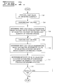
- FIG. 6 is a flow diagram illustrating a preferred method of the present invention.
- FIG. 7 is a flow diagram illustrating a preferred method associated with the aspect of FIG. 2;
- FIG. 8 is a flow diagram illustrating a preferred method associated with the aspect of FIG. 3.
- FIG. 9 is a flow diagram illustrating a preferred method associated with the aspect of FIG. 5 .
- a method and apparatus 100 for determining a location of an underground object during a digging operation is shown.
- a work machine 102 is used to perform the digging operation.
- the work machine 102 is depicted as a backhoe loader, having a work implement 104 attached, preferably shown as a bucket.
- a work implement 104 attached to the digging operation.
- other types of work machines e.g., excavators, front shovels, augers, trenchers, and the like, may be used with the present invention.
- other types of work implements e.g., boring tools, trenching tools, blades, and the like, may also be used.
- the work machine 102 is used to dig into the ground 106 , e.g., soil, sand, rock, and various other types of material which may be classified as ground 106 . It is often the case in the construction and earthworking industries that the digging operation takes place in the proximity of at least one underground object 108 . For example, utility lines and pipes, underground tanks, and even military ordinance may be located in the ground 106 at the location at which digging is to take place.
- a signal is delivered toward the underground object 108 .
- a reflected signal is received from the underground object 108 .
- the signal is delivered and received by a means 404 for delivering and receiving a signal, preferably a ground penetrating radar (GPR) antenna 406 .
- GPR ground penetrating radar
- other means 404 for delivering and receiving a signal such as acoustic, ultrasonic, and the like, may be used without deviating from the scope of the present invention.
- the means 404 for delivering and receiving a signal is referred to below as a GPR antenna 406 .
- an initial location of the underground object 108 is determined.
- the initial location is determined with respect to a depth in the ground 106 , and a location relative to the dig location of the work implement 104 .
- a region of uncertainty 110 is created around the underground object 108 as a function of a level of confidence of the determined initial location.
- the level of confidence is preferably a function of how accurate the initial determined location is believed to be, and depends on such factors as the known dielectric constant of the ground 106 (discussed in more detail below), the amount of detail obtained from the GPR signal (also discussed in more detail below), and the like.
- the size of the region of uncertainty 110 is inversely proportional to the level of confidence, i.e., as the level of confidence increases, the size of the region of uncertainty 110 decreases.
- control block 610 at least one process is performed to improve the level of confidence. Examples of processes which may be used are discussed in detail below. As the level of confidence is improved, control proceeds to a sixth control block 612 , in which the region of uncertainty 110 is adjusted as a function of the improved level of confidence, as described above.
- a controller 402 is preferably used to perform the controlling functions of the present invention.
- the controller 402 is preferably microprocessor based, and is adapted to control operation of the GPR antenna 406 , and to receive GPR signals as they are received from the underground object 108 .
- the controller 402 is also adapted to determine the initial location of the underground object 108 , determine the region of uncertainty 110 , and adjust the region of uncertainty 110 as a function of the level of confidence.
- a position determining system 408 for example a geo-referenced position determining system, preferably located on the work machine 102 , is adapted to determine the position of the work implement 104 by methods which are well known in the art.
- a position determining system such as a global positioning satellite (GPS) system, used in cooperation with various machine position sensors, may be used to determine the position of the bucket in geographical coordinates.
- GPS global positioning satellite
- the position information from the position determining system 408 is delivered to the controller 402 , which is further adapted to control the movement and position of the work implement 104 .
- a display 410 may be used to provide a visual indication of the location of at least one of the work implement 104 , the underground object 108 , and the region of uncertainty 110 relative to the ground 106 , i.e., relative to the work machine 102 situated on the ground 106 .
- the display 410 may be located on the work machine 102 for viewing by an operator or may be located at a remote site for monitoring by someone else.
- a first value of a dielectric constant of the ground 106 is estimated based on an assumption of properties of the ground 106 .
- the propagation velocity of the signal, as it passes through the ground 106 is generally a function of the dielectric constant of the material comprising the ground 106 .
- the dielectric constant therefore, is an important parameter to determine with accuracy the distance a GPR signal travels to the underground object 108 and back.
- a first dig pass is performed. Typically, in a digging operation, many dig passes will be required to accomplish the task.
- a first location of the underground object 108 is determined as a function of the estimated first value of dielectric constant and a known first quantity of removed ground 106 .
- the first quantity of removed ground 106 is readily determined by knowing the position of the work implement 104 , as described above with reference to the position determining system 408 , and by knowing the physical dimensions of the work implement 104 . As shown in FIG. 2, the first quantity of removed ground 106 is depicted as first dig pass 202 .
- a next dig pass is performed, i.e., as represented by the second dig pass 204 in FIG. 2 .
- a next known quantity of ground 106 is removed.
- a next location of the underground object 108 is determined as a function of the estimated value of the dielectric constant and the next known quantity of removed ground 106 . Since the second dig pass 204 in effect moves the surface of the ground 106 closer to the underground object 108 , the next determined location of the underground object should in theory be the initial location minus the amount of ground 106 removed. However, the GPR signal should be more accurate due to the closer proximity, and consequently any error in the estimated value of dielectric constant will be embodied as a difference in value from the initial determined location of the underground object 108 and the next determined location of the underground object 108 .
- an improved value of dielectric constant is determined as a function of a comparison of the current determined location of the underground object 108 with the previous determined location of the underground object 108 .
- a first decision block 714 if another dig pass is to be made, control proceeds to the fourth control block 708 , and loops through the fourth control block 708 , the fifth control block 710 and the sixth control block 712 until no more dig passes are to be made.
- a third dig pass 206 is made, and so forth until digging is complete.
- the determined location of the underground object 108 at each dig pass is compared to the determined location at the previous dig pass, and a new value of dielectric constant is determined.
- the dielectric constant by repeated iterations, approaches a more accurate value, resulting in more accurate determinations of the actual location of the underground object 108 , and the level of confidence becomes higher. Consequently, the region of uncertainty 110 is reduced, and the digging operation is free to approach the underground object 108 more closely and accurately.
- the GPR signal is delivered from a plurality of locations toward the underground object 108 .
- this may be accomplished by mounting the GPR antenna 406 directly to the work implement 104 .
- the GPR antenna 406 directs the GPR signal from several positions.
- the controller 402 preferably directs the GPR antenna 406 as to the rate of repetition of the delivered signals.
- a corresponding plurality of reflected signals are received from the underground object 108 .
- the plurality of reflected signals are then superimposed in a third control block 806 to determine a three-dimensional location of the underground object 108 , and to determine a size and shape of the underground object 108 .
- the plurality of received GPR signals and the superimposed three-dimensional determined location of the underground object 108 offer a more accurate determination of the location of the underground object 108 . Therefore, the level of confidence is increased, thus resulting in a reduced region of uncertainty 110 .
- the three-dimensional determination of the size and shape of the underground object 108 provides an improved means of recognizing the identity of the underground object 108 .
- FIG. 9 an alternative embodiment to the method described in FIG. 8 is shown.
- a plurality of GPR signals from a plurality of locations are delivered toward the underground object 108 .
- a plurality of GPR antennas 406 a , 406 b , 406 c are located at fixed positions, each GPR antenna 406 delivering a signal toward the underground object 108 .
- FIG. 5 shows three GPR antennas, any desired quantity may be used.
- the GPR antennas 406 may be mounted at various locations on the work machine 102 , may be located in fixed position at locations remote from the work machine 102 , or any combination of the above.
- one or more GPR antennas 406 may be mounted on the work implement 104 to achieve a combination of the present embodiment and the embodiment described with reference to FIG. 8 .
- the controller 402 is adapted to coordinate the delivery of GPR signals from each of the GPR antennas 406 to the underground object 108 .
- a corresponding plurality of reflected signals are received from the underground object 108 .
- the plurality of reflected signals are then superimposed in a third control block 906 to determine a three-dimensional location of the underground object 108 , and to determine a size and shape of the underground object 108 .
- an operator of a work machine 102 such as a backhoe loader, must work with caution to avoid underground objects 108 as digging takes place.
- the advent of GPR technology allows the operator some assurance that an underground object 108 is located within a certain area, but inaccuracies exist due to unknowns, such as characteristics of the ground 106 , e.g., the dielectric constant of the ground 106 .
- the present invention is adapted to overcome these problems by using information obtained during the digging operations to improve the accuracy of locating underground objects 108 , and thus to increase the confidence level of the machine operator as to the location of any objects to be avoided.
- Other aspects, objects, and features of the present invention can be obtained from a study of the drawings, the disclosure, and the appended claims.
Landscapes
- Engineering & Computer Science (AREA)
- Mining & Mineral Resources (AREA)
- Life Sciences & Earth Sciences (AREA)
- General Life Sciences & Earth Sciences (AREA)
- Paleontology (AREA)
- Civil Engineering (AREA)
- General Engineering & Computer Science (AREA)
- Structural Engineering (AREA)
- Radar Systems Or Details Thereof (AREA)
- Geophysics And Detection Of Objects (AREA)
- Shovels (AREA)
- Operation Control Of Excavators (AREA)
Abstract
A method and apparatus for determining a location of an underground object during a digging operation. The method and apparatus includes delivering a signal toward the underground object, receiving a reflected signal from the underground object, determining an initial location of the underground object, creating a region of uncertainty around the underground object as a function of a level of confidence of the determined initial location, performing at least one process to improve the level of confidence, and adjusting the region of uncertainty as a function of the improved level of confidence.
Description
This invention relates generally to a method and apparatus for locating underground objects during a digging operation and, more particularly, to a method and apparatus for determining the location of underground objects with an improved level of confidence during digging.
Earthworking machines, such as backhoes and excavators, are used to dig the earth. During the digging process, it is critical to avoid contact with underground objects such as pipes and lines. However, it is difficult, if not impossible, to know the exact locations of underground objects, and thus digging is slowed down substantially as the digging implement approaches what is believed to be the approximate location of the object to be avoided.
Advances in technologies, such as ground penetrating radar (GPR), have allowed earthworking operators some degree of confidence in determining the locations of underground objects. However, GPR cannot be used to determine the locations of underground objects with accuracy, due to variable propagation characteristics of the soil, and also due to the inherent two dimensional characteristics of the GPR signals.
The present invention is directed to overcoming one or more of the problems as set forth above.
In one aspect of the present invention a method for determining a location of an underground object during a digging operation is disclosed. The method includes the steps of delivering a signal toward the underground object, receiving a reflected signal from the underground object, determining an initial location of the underground object, creating a region of uncertainty around the underground object as a function of a level of confidence of the determined initial location, performing at least one process to improve the level of confidence, and adjusting the region of uncertainty as a function of the improved level of confidence.
In another aspect of the present invention an apparatus for determining a location of an underground object during a digging operation is disclosed. The apparatus includes means for delivering a signal toward the underground object and for receiving a corresponding reflected signal from the underground object, and a controller adapted to determine an initial location of the underground object, create a region of uncertainty around the underground object as a function of a level of confidence of the determined initial location, perform at least one process to improve the level of confidence, and adjust the region of uncertainty as a function of the improved level of confidence.
FIG. 1 is a diagrammatic illustration of a preferred embodiment of the present invention;
FIG. 2 is a diagrammatic illustration of one aspect of the present invention;
FIG. 3 is a diagrammatic illustration of another aspect of the present invention;
FIG. 4 is a block diagram illustrating a preferred apparatus suited for use with the present invention;
FIG. 5 is a diagrammatic illustration of yet another aspect of the present invention;
FIG. 6 is a flow diagram illustrating a preferred method of the present invention;
FIG. 7 is a flow diagram illustrating a preferred method associated with the aspect of FIG. 2;
FIG. 8 is a flow diagram illustrating a preferred method associated with the aspect of FIG. 3; and
FIG. 9 is a flow diagram illustrating a preferred method associated with the aspect of FIG. 5.
Referring to the drawings, a method and apparatus 100 for determining a location of an underground object during a digging operation is shown. With particular reference to FIG. 1, a work machine 102 is used to perform the digging operation. The work machine 102 is depicted as a backhoe loader, having a work implement 104 attached, preferably shown as a bucket. However, other types of work machines, e.g., excavators, front shovels, augers, trenchers, and the like, may be used with the present invention. In addition, other types of work implements, e.g., boring tools, trenching tools, blades, and the like, may also be used.
Typically, the work machine 102 is used to dig into the ground 106, e.g., soil, sand, rock, and various other types of material which may be classified as ground 106. It is often the case in the construction and earthworking industries that the digging operation takes place in the proximity of at least one underground object 108. For example, utility lines and pipes, underground tanks, and even military ordinance may be located in the ground 106 at the location at which digging is to take place.
The present invention is described below with reference to the flow diagrams depicted in FIGS. 6-9 to describe a preferred method of the present invention, and with periodic reference to FIGS. 2-5 to illustrate an accompanying preferred apparatus 100 of the present invention.
Referring to FIG. 6, in a first control block 602, a signal is delivered toward the underground object 108. In a second control block 604, a reflected signal is received from the underground object 108. The signal, as shown in FIG. 4, is delivered and received by a means 404 for delivering and receiving a signal, preferably a ground penetrating radar (GPR) antenna 406. Alternatively, other means 404 for delivering and receiving a signal, such as acoustic, ultrasonic, and the like, may be used without deviating from the scope of the present invention. For purposes of explanation of the present invention, however, the means 404 for delivering and receiving a signal is referred to below as a GPR antenna 406.
In a third control block 606, an initial location of the underground object 108 is determined. Preferably, the initial location is determined with respect to a depth in the ground 106, and a location relative to the dig location of the work implement 104.
In a fourth control block 608, a region of uncertainty 110 is created around the underground object 108 as a function of a level of confidence of the determined initial location. The level of confidence is preferably a function of how accurate the initial determined location is believed to be, and depends on such factors as the known dielectric constant of the ground 106 (discussed in more detail below), the amount of detail obtained from the GPR signal (also discussed in more detail below), and the like. In the preferred embodiment, the size of the region of uncertainty 110 is inversely proportional to the level of confidence, i.e., as the level of confidence increases, the size of the region of uncertainty 110 decreases.
In a fifth control block 610, at least one process is performed to improve the level of confidence. Examples of processes which may be used are discussed in detail below. As the level of confidence is improved, control proceeds to a sixth control block 612, in which the region of uncertainty 110 is adjusted as a function of the improved level of confidence, as described above.
Referring to FIG. 4, a controller 402 is preferably used to perform the controlling functions of the present invention. The controller 402 is preferably microprocessor based, and is adapted to control operation of the GPR antenna 406, and to receive GPR signals as they are received from the underground object 108. The controller 402 is also adapted to determine the initial location of the underground object 108, determine the region of uncertainty 110, and adjust the region of uncertainty 110 as a function of the level of confidence.
A position determining system 408, for example a geo-referenced position determining system, preferably located on the work machine 102, is adapted to determine the position of the work implement 104 by methods which are well known in the art. For example, in a backhoe loader having a boom, stick, and a bucket, a position determining system, such as a global positioning satellite (GPS) system, used in cooperation with various machine position sensors, may be used to determine the position of the bucket in geographical coordinates.
The position information from the position determining system 408 is delivered to the controller 402, which is further adapted to control the movement and position of the work implement 104.
A display 410 may be used to provide a visual indication of the location of at least one of the work implement 104, the underground object 108, and the region of uncertainty 110 relative to the ground 106, i.e., relative to the work machine 102 situated on the ground 106. The display 410 may be located on the work machine 102 for viewing by an operator or may be located at a remote site for monitoring by someone else.
Referring to FIG. 7, and with reference to FIG. 2, a preferred method for a process to improve the level of confidence is disclosed.
In a first control block 702, a first value of a dielectric constant of the ground 106 is estimated based on an assumption of properties of the ground 106. As is well known in GPR theory, the propagation velocity of the signal, as it passes through the ground 106, is generally a function of the dielectric constant of the material comprising the ground 106. The dielectric constant, therefore, is an important parameter to determine with accuracy the distance a GPR signal travels to the underground object 108 and back. However, it is difficult to know the value of dielectric constant with accuracy without conducting prior tests, which are costly and time consuming. Therefore, the assumption of the first value of dielectric constant is made as a best estimate, based on past experience with soil conditions.
In a second control block 704, a first dig pass is performed. Typically, in a digging operation, many dig passes will be required to accomplish the task.
In a third control block 706, a first location of the underground object 108 is determined as a function of the estimated first value of dielectric constant and a known first quantity of removed ground 106. The first quantity of removed ground 106 is readily determined by knowing the position of the work implement 104, as described above with reference to the position determining system 408, and by knowing the physical dimensions of the work implement 104. As shown in FIG. 2, the first quantity of removed ground 106 is depicted as first dig pass 202.
In a fourth control block 708, a next dig pass is performed, i.e., as represented by the second dig pass 204 in FIG. 2. During the next dig pass, a next known quantity of ground 106 is removed.
In a fifth control block 710, a next location of the underground object 108 is determined as a function of the estimated value of the dielectric constant and the next known quantity of removed ground 106. Since the second dig pass 204 in effect moves the surface of the ground 106 closer to the underground object 108, the next determined location of the underground object should in theory be the initial location minus the amount of ground 106 removed. However, the GPR signal should be more accurate due to the closer proximity, and consequently any error in the estimated value of dielectric constant will be embodied as a difference in value from the initial determined location of the underground object 108 and the next determined location of the underground object 108.
Therefore, in a sixth control block 712, an improved value of dielectric constant is determined as a function of a comparison of the current determined location of the underground object 108 with the previous determined location of the underground object 108.
In a first decision block 714, if another dig pass is to be made, control proceeds to the fourth control block 708, and loops through the fourth control block 708, the fifth control block 710 and the sixth control block 712 until no more dig passes are to be made. As exemplified in FIG. 2, a third dig pass 206 is made, and so forth until digging is complete. During these cycles, the determined location of the underground object 108 at each dig pass is compared to the determined location at the previous dig pass, and a new value of dielectric constant is determined. In this way, the dielectric constant, by repeated iterations, approaches a more accurate value, resulting in more accurate determinations of the actual location of the underground object 108, and the level of confidence becomes higher. Consequently, the region of uncertainty 110 is reduced, and the digging operation is free to approach the underground object 108 more closely and accurately.
Referring to FIG. 8, and with reference to FIG. 3, a preferred method for another process to improve the level of confidence is disclosed.
In a first control block 802, the GPR signal is delivered from a plurality of locations toward the underground object 108. As embodied in FIG. 3, this may be accomplished by mounting the GPR antenna 406 directly to the work implement 104. Thus, as the work implement 104 moves in an arc to perform a dig pass (as shown by 104 a,b,c,d), the GPR antenna 406 directs the GPR signal from several positions. The controller 402 preferably directs the GPR antenna 406 as to the rate of repetition of the delivered signals.
In a second control block 804, a corresponding plurality of reflected signals are received from the underground object 108. The plurality of reflected signals are then superimposed in a third control block 806 to determine a three-dimensional location of the underground object 108, and to determine a size and shape of the underground object 108. The plurality of received GPR signals and the superimposed three-dimensional determined location of the underground object 108 offer a more accurate determination of the location of the underground object 108. Therefore, the level of confidence is increased, thus resulting in a reduced region of uncertainty 110. Furthermore, the three-dimensional determination of the size and shape of the underground object 108 provides an improved means of recognizing the identity of the underground object 108.
Referring to FIG. 9, and with reference to FIG. 5, an alternative embodiment to the method described in FIG. 8 is shown.
In a first control block 902, a plurality of GPR signals from a plurality of locations are delivered toward the underground object 108. For example, as shown in FIG. 5, a plurality of GPR antennas 406 a,406 b,406 c are located at fixed positions, each GPR antenna 406 delivering a signal toward the underground object 108. Although FIG. 5 shows three GPR antennas, any desired quantity may be used. The GPR antennas 406 may be mounted at various locations on the work machine 102, may be located in fixed position at locations remote from the work machine 102, or any combination of the above. Furthermore, one or more GPR antennas 406 may be mounted on the work implement 104 to achieve a combination of the present embodiment and the embodiment described with reference to FIG. 8. In the preferred embodiment, the controller 402 is adapted to coordinate the delivery of GPR signals from each of the GPR antennas 406 to the underground object 108.
In a second control block 904, a corresponding plurality of reflected signals are received from the underground object 108. The plurality of reflected signals are then superimposed in a third control block 906 to determine a three-dimensional location of the underground object 108, and to determine a size and shape of the underground object 108.
Industrial Applicability
As an example of an application of the present invention, an operator of a work machine 102, such as a backhoe loader, must work with caution to avoid underground objects 108 as digging takes place. The advent of GPR technology allows the operator some assurance that an underground object 108 is located within a certain area, but inaccuracies exist due to unknowns, such as characteristics of the ground 106, e.g., the dielectric constant of the ground 106.
The present invention is adapted to overcome these problems by using information obtained during the digging operations to improve the accuracy of locating underground objects 108, and thus to increase the confidence level of the machine operator as to the location of any objects to be avoided. Other aspects, objects, and features of the present invention can be obtained from a study of the drawings, the disclosure, and the appended claims.
Claims (20)
1. A method for determining a location of an underground object during a digging operation, including the steps of:
delivering a signal toward the underground object;
receiving a reflected signal from the underground object;
determining an initial location of the underground object;
creating a region of uncertainty around the underground object as a function of a level of confidence of the determined initial location;
performing at least one process to improve the level of confidence; and
adjusting the region of uncertainty as a function of the improved level of confidence.
2. A method, as set forth in claim 1 , wherein performing at least one process includes the steps of:
a) estimating a first value of dielectric constant of the ground to be dug;
b) performing a first dig pass;
c) determining a first location of the underground object as a function of the estimated first value of dielectric constant and a known first quantity of removed ground;
d) performing a next dig pass;
e) determining a next location of the underground object as a function of the estimated value of dielectric constant and a next known quantity of removed ground;
f) determining an improved value of dielectric constant as a function of a comparison of the current determined location and a previous determined location; and
g) repeating steps d) through f) for each subsequent dig pass.
3. A method, as set forth in claim 2 , wherein performing a dig pass includes the steps of:
determining a position of a work implement during the digging operation, the work implement having known dimensions; and
determining a quantity of removed ground during the dig pass as a function of the determined position and the known dimensions of the work implement.
4. A method, as set forth in claim 3 , further including the step of controlling the position of the work implement as a function of the region of uncertainty.
5. A method, as set forth in claim 3 , further including the step of displaying at least one of the work implement, the underground object, and the region of uncertainty relative to the ground.
6. A method, as set forth in claim 1 , wherein performing at least one process includes the steps of:
delivering a signal from a plurality of locations toward the underground object;
receiving a corresponding plurality of reflected signals from the underground object; and
superimposing the plurality of reflected signals to determine a three-dimensional determination of a location of the underground object, and to determine an estimate of a size and shape of the underground object.
7. A method, as set forth in claim 6 , wherein the delivered signal is delivered from a work implement as the work implement moves to perform a dig pass.
8. A method, as set forth in claim 6 , wherein the delivered signal is delivered from a plurality of fixed locations.
9. A method, as set forth in claim 1 , wherein performing at least one process includes the steps of:
delivering a plurality of signals from a plurality of locations toward the underground object;
receiving a corresponding plurality of reflected signals from the underground object; and
superimposing the plurality of reflected signals to determine a three-dimensional determination of a location of the underground object, and to determine an estimate of a size and shape of the underground object.
10. A method, as set forth in claim 1 , wherein delivering a signal includes the step of delivering a ground penetrating radar signal.
11. An apparatus for determining a location of an underground object during a digging operation, comprising:
means for delivering a signal toward the underground object and for receiving a corresponding reflected signal from the underground object; and
a controller for determining an initial location of the underground object, creating a region of uncertainty around the underground object as a function of a level of confidence of the determined initial location, performing at least one process to improve the level of confidence, and adjusting the region of uncertainty as a function of the improved level of confidence.
12. An apparatus, as set forth in claim 11 , wherein the controller is further for:
a) estimating a first value of dielectric constant of the ground to be dug;
b) performing a first dig pass;
c) determining a first location of the underground object as a function of the estimated first value of dielectric constant and a known first quantity of removed ground;
d) performing a next dig pass;
e) determining a next location of the underground object as a function of the estimated value of dielectric constant and a next known quantity of removed ground;
f) determining an improved value of dielectric constant as a function of a comparison of the current determined location and a previous determined location; and
g) repeating steps d) through f) for each subsequent dig pass.
13. An apparatus, as set forth in claim 12 , further including a position determining system for determining a position of a work implement during the digging operation, the work implement having known dimensions, and wherein the controller is further for determining a quantity of removed ground during the dig pass as a function of the determined position and the known dimensions of the work implement.
14. An apparatus, as set forth in claim 13 , wherein the controller is further for controlling the position of the work implement as a function of the region of uncertainty.
15. An apparatus, as set forth in claim 13 , further including a display for displaying at least one of the work implement, the underground object, and the region of uncertainty relative to the ground.
16. An apparatus, as set forth in claim 11 , wherein the controller is further for:
delivering a signal from a plurality of locations toward the underground object;
receiving a corresponding plurality of reflected signals from the underground object; and
superimposing the plurality of reflected signals to determine a three-dimensional determination of a location of the underground object, and to determine an estimate of a size and shape of the underground object.
17. An apparatus, as set forth in claim 16 , wherein the means for delivering a signal and for receiving a corresponding reflected signal includes a ground penetrating radar (GPR) antenna.
18. An apparatus, as set forth in claim 17 , wherein the GPR antenna is mounted on the work implement.
19. An apparatus, as set forth in claim 11 , wherein the controller is further for:
delivering a plurality of signals from a plurality of locations toward the underground object;
receiving a corresponding plurality of reflected signals from the underground object; and
superimposing the plurality of reflected signals to determine a three-dimensional determination of a location of the underground object, and to determine an estimate of a size and shape of the underground object.
20. An apparatus, as set forth in claim 19 , wherein the means for delivering a signal and for receiving a corresponding reflected signal includes a plurality of ground penetrating radar (GPR) antennas located at a plurality of predetermined locations to deliver a corresponding plurality of signals.
Priority Applications (5)
| Application Number | Priority Date | Filing Date | Title |
|---|---|---|---|
| US09/726,905 US6437726B1 (en) | 2000-11-30 | 2000-11-30 | Method and apparatus for determining the location of underground objects during a digging operation |
| DE60136299T DE60136299D1 (en) | 2000-11-30 | 2001-10-18 | METHOD AND DEVICE FOR DETERMINING THE LOCATION OF UNDERGROUND GOODS DURING A TRADING WORK |
| JP2002546819A JP4286539B2 (en) | 2000-11-30 | 2001-10-18 | Method and apparatus for determining the position of an object in the ground during excavation work |
| PCT/US2001/029678 WO2002044478A2 (en) | 2000-11-30 | 2001-10-18 | Method and apparatus for determining the location of undergroung objects during a digging operation |
| EP01971295A EP1379735B1 (en) | 2000-11-30 | 2001-10-18 | Method and apparatus for determining the location of underground objects during a digging operation |
Applications Claiming Priority (1)
| Application Number | Priority Date | Filing Date | Title |
|---|---|---|---|
| US09/726,905 US6437726B1 (en) | 2000-11-30 | 2000-11-30 | Method and apparatus for determining the location of underground objects during a digging operation |
Publications (2)
| Publication Number | Publication Date |
|---|---|
| US20020063652A1 US20020063652A1 (en) | 2002-05-30 |
| US6437726B1 true US6437726B1 (en) | 2002-08-20 |
Family
ID=24920521
Family Applications (1)
| Application Number | Title | Priority Date | Filing Date |
|---|---|---|---|
| US09/726,905 Expired - Lifetime US6437726B1 (en) | 2000-11-30 | 2000-11-30 | Method and apparatus for determining the location of underground objects during a digging operation |
Country Status (5)
| Country | Link |
|---|---|
| US (1) | US6437726B1 (en) |
| EP (1) | EP1379735B1 (en) |
| JP (1) | JP4286539B2 (en) |
| DE (1) | DE60136299D1 (en) |
| WO (1) | WO2002044478A2 (en) |
Cited By (32)
| Publication number | Priority date | Publication date | Assignee | Title |
|---|---|---|---|---|
| US20020130806A1 (en) * | 2001-03-12 | 2002-09-19 | Ensco, Inc. | Method and apparatus for detecting, mapping and locating underground utilities |
| US6735888B2 (en) * | 2001-05-18 | 2004-05-18 | Witten Technologies Inc. | Virtual camera on the bucket of an excavator displaying 3D images of buried pipes |
| US20040117093A1 (en) * | 2002-12-12 | 2004-06-17 | Koch Roger D. | System for estimating a linkage position |
| US20050033456A1 (en) * | 2001-08-06 | 2005-02-10 | Honda Giken Kogyo Kabushiki Kaisha | Control system for plant and air-fuel ratio control system for internal combustion engine |
| US20050096883A1 (en) * | 2003-04-03 | 2005-05-05 | Gordon Pacey | Buried line locator with integral position sensing |
| US20050273291A1 (en) * | 2004-06-06 | 2005-12-08 | Zukowski Deborra J | Method and system for determining location by implication |
| US20060265914A1 (en) * | 2005-05-31 | 2006-11-30 | Caterpillar Inc. | Work machine having boundary tracking system |
| US7178606B2 (en) | 2004-08-27 | 2007-02-20 | Caterpillar Inc | Work implement side shift control and method |
| US20080079723A1 (en) * | 2006-05-16 | 2008-04-03 | David Hanson | System and method for visualizing multiple-sensor subsurface imaging data |
| US20080133128A1 (en) * | 2006-11-30 | 2008-06-05 | Caterpillar, Inc. | Excavation control system providing machine placement recommendation |
| US20080162004A1 (en) * | 2006-12-27 | 2008-07-03 | Price Robert J | Machine control system and method |
| US7400976B2 (en) * | 2000-06-14 | 2008-07-15 | Vermeer Manufacturing Company | Utility mapping and data distribution system and method |
| US20090045808A1 (en) * | 2006-01-29 | 2009-02-19 | Eli Mano | System for testing concealed conduits |
| US20090185865A1 (en) * | 2005-11-16 | 2009-07-23 | The Charles Machine Works, Inc. | Soft excavation potholing method and apparatus |
| US20100052684A1 (en) * | 2006-12-01 | 2010-03-04 | Leica Geosystems Ag | Localization system for an earthmoving machine |
| US20100074694A1 (en) * | 2008-09-25 | 2010-03-25 | Terra Shield, Llc | Methods for the subterranean support of underground conduits |
| US20100245542A1 (en) * | 2007-08-02 | 2010-09-30 | Inha-Industry Partnership Institute | Device for computing the excavated soil volume using structured light vision system and method thereof |
| US20100259438A1 (en) * | 2006-05-16 | 2010-10-14 | Ross Peter Jones | Sensor cart positioning system and method |
| US20100263892A1 (en) * | 2009-04-16 | 2010-10-21 | Hercules Machinery Corporation | Method and apparatus for facilitating the subterranean support of underground conduits having a fixed insertion axis |
| US20110008111A1 (en) * | 2009-07-10 | 2011-01-13 | Hercules Machinery Corporation | Apparatus for inserting sheet pile having an independently adjustable insertion axis and method for using the same |
| EP2278358A1 (en) | 2009-07-22 | 2011-01-26 | Leica Geosystems AG | Method and system for detecting the proximity of a conductive, buried structure |
| EP2362241A1 (en) | 2010-02-25 | 2011-08-31 | Leica Geosystems AG | Electromagnetic proximity detection Method and Unit |
| EP2645133A1 (en) | 2012-03-30 | 2013-10-02 | Leica Geosystems AG | Buried service detection |
| US20130255574A1 (en) * | 2009-04-07 | 2013-10-03 | John Cunningham | Sensor system for explosive detection and removal |
| US9052394B2 (en) | 2009-10-06 | 2015-06-09 | Louisiana Tech University Research Foundation | Method and apparatus for detecting buried objects |
| US9103079B2 (en) | 2013-10-25 | 2015-08-11 | Caterpillar Paving Products Inc. | Ground characteristic milling machine control |
| US9348020B2 (en) | 2012-03-12 | 2016-05-24 | Vermeer Manufacturing Company | Offset frequency homodyne ground penetrating radar |
| US9739133B2 (en) | 2013-03-15 | 2017-08-22 | Vermeer Corporation | Imaging underground objects using spatial sampling customization |
| US20170278425A1 (en) * | 2016-03-28 | 2017-09-28 | Komatsu Ltd. | Evaluation apparatus and evaluation method |
| US20200299924A1 (en) * | 2017-12-21 | 2020-09-24 | Sumitomo Construction Machinery Co., Ltd. | Shovel and system of managing shovel |
| US11120692B2 (en) * | 2019-05-24 | 2021-09-14 | Saudi Arabian Oil Company | Systems and methods for preventing damage to unseen utility assets |
| US20230097590A1 (en) * | 2020-02-27 | 2023-03-30 | Cnh Industrial America Llc | Electric drivetrain and component storage configurations for an electric work vehicle |
Families Citing this family (21)
| Publication number | Priority date | Publication date | Assignee | Title |
|---|---|---|---|---|
| US20060034535A1 (en) * | 2004-08-10 | 2006-02-16 | Koch Roger D | Method and apparatus for enhancing visibility to a machine operator |
| WO2008005837A2 (en) * | 2006-06-30 | 2008-01-10 | Global Precision Solutions, Llp. | System and method for digging navigation |
| TWI370638B (en) * | 2006-12-22 | 2012-08-11 | Ind Tech Res Inst | Method for determining the confidence index of the estimated position for a target device in a wireless system |
| ATE503891T1 (en) * | 2007-09-13 | 2011-04-15 | Dredging Int | METHOD AND SYSTEM FOR OPTIMIZING EXCAVATING |
| KR101028145B1 (en) | 2009-12-29 | 2011-04-08 | (주)한국에스코 | Excavator with detector for protection of underground cables |
| WO2012170024A1 (en) * | 2011-06-09 | 2012-12-13 | Deere & Company | System and method for ground penetrating radar communication using antenna crosstalk |
| US11530605B2 (en) * | 2015-03-13 | 2022-12-20 | The Charles Machine Works, Inc. | Horizontal directional drilling crossbore detector |
| NL2015191B1 (en) * | 2015-07-20 | 2017-02-07 | Zm Holding B V | A device for cutting a volume of material out of a piece of ground and a method wherein said device can be used. |
| EP3399111B1 (en) * | 2015-12-28 | 2020-04-15 | Sumitomo (S.H.I.) Construction Machinery Co., Ltd. | Shovel |
| DE102016207973A1 (en) | 2016-05-10 | 2017-11-16 | Robert Bosch Gmbh | System for detecting objects in the ground |
| US10151830B2 (en) * | 2016-09-14 | 2018-12-11 | Caterpillar Inc. | Systems and methods for detecting objects proximate to a machine utilizing a learned process |
| JP7188940B2 (en) * | 2018-08-31 | 2022-12-13 | 株式会社小松製作所 | Control device, loading machine and control method |
| JP7093277B2 (en) * | 2018-09-14 | 2022-06-29 | 日立建機株式会社 | Work machine |
| JP6970079B2 (en) * | 2018-11-30 | 2021-11-24 | すみえ 池田 | Ground penetrating radar |
| JP7322616B2 (en) * | 2019-09-12 | 2023-08-08 | 東京電力ホールディングス株式会社 | Information processing device, information processing method, program and drilling system |
| US11215781B1 (en) * | 2020-11-30 | 2022-01-04 | Cciip Llc | Roadway access hole cutter having a utility avoidance safety device, method of cutting a hole in a roadway, method of cutting a horizontal hole under a roadway |
| CN113344086B (en) * | 2021-06-16 | 2022-07-01 | 深圳市商汤科技有限公司 | Man-machine loop method, device, system, electronic equipment and storage medium |
| KR102371895B1 (en) * | 2021-09-14 | 2022-03-07 | 오순옥 | Force Measuring Apparatus of Ground Anchor and Tensile Force Measuring Method of Ground Anchor Using the Same |
| US20250314047A1 (en) * | 2024-04-09 | 2025-10-09 | Deere & Company | Work machine implement control for autonomous subterranean surveying and marking applications |
| WO2026048007A1 (en) * | 2024-08-30 | 2026-03-05 | Ntt株式会社 | Search system |
| CN120719721A (en) * | 2025-09-02 | 2025-09-30 | 福建华南重工机械制造有限公司 | Method for excavator operating accessories to avoid municipal facilities and excavator |
Citations (13)
| Publication number | Priority date | Publication date | Assignee | Title |
|---|---|---|---|---|
| US3745575A (en) * | 1971-02-09 | 1973-07-10 | Kikuchi Sci & Res Labor | Method of detecting subsurface objects |
| US3775765A (en) * | 1971-12-08 | 1973-11-27 | Bell Telephone Labor Inc | System for resolving the sizes and centroid locations of buried objects |
| US4072942A (en) * | 1976-02-20 | 1978-02-07 | Calspan Corporation | Apparatus for the detection of buried objects |
| US4600356A (en) | 1984-01-27 | 1986-07-15 | Gas Research Institute | Underground pipeline and cable detector and process |
| US5357253A (en) * | 1993-04-02 | 1994-10-18 | Earth Sounding International | System and method for earth probing with deep subsurface penetration using low frequency electromagnetic signals |
| US5592092A (en) | 1994-10-28 | 1997-01-07 | Gas Research Institute | Pipe proximity warning device for accidental damage prevention mounted on the bucket of a backhoe |
| US5647439A (en) | 1995-12-14 | 1997-07-15 | Caterpillar Inc. | Implement control system for locating a surface interface and removing a layer of material |
| US5673050A (en) * | 1996-06-14 | 1997-09-30 | Moussally; George | Three-dimensional underground imaging radar system |
| US5704142A (en) | 1995-06-19 | 1998-01-06 | Vermeer Manufacturing Company | Excavator data acquisition and control system and process |
| US5812081A (en) * | 1984-12-03 | 1998-09-22 | Time Domain Systems, Inc. | Time domain radio transmission system |
| GB2337120A (en) | 1998-05-07 | 1999-11-10 | Radiodetection Ltd | Detecting underground conductors |
| US6076030A (en) | 1998-10-14 | 2000-06-13 | Carnegie Mellon University | Learning system and method for optimizing control of autonomous earthmoving machinery |
| US6282477B1 (en) | 2000-03-09 | 2001-08-28 | Caterpillar Inc. | Method and apparatus for displaying an object at an earthworking site |
Family Cites Families (6)
| Publication number | Priority date | Publication date | Assignee | Title |
|---|---|---|---|---|
| JPH0799396B2 (en) * | 1988-05-06 | 1995-10-25 | 株式会社小松製作所 | Buried object exploration equipment |
| JPH06138250A (en) * | 1992-10-27 | 1994-05-20 | Osaka Gas Co Ltd | Method and device for measuring relative dielectric constant and method and device for probing buried object |
| JPH06230141A (en) * | 1993-02-03 | 1994-08-19 | Hitachi Constr Mach Co Ltd | Excavating equipment provided with underground probe |
| US6191585B1 (en) * | 1996-05-03 | 2001-02-20 | Digital Control, Inc. | Tracking the positional relationship between a boring tool and one or more buried lines using a composite magnetic signal |
| JPH10325880A (en) * | 1997-03-28 | 1998-12-08 | Sekisui Chem Co Ltd | Method of measuring relative permittivity or buried position of buried object, and measuring device therefor |
| JPH11118943A (en) * | 1997-10-13 | 1999-04-30 | Nippon Telegr & Teleph Corp <Ntt> | Direct signal processor for search radar |
-
2000
- 2000-11-30 US US09/726,905 patent/US6437726B1/en not_active Expired - Lifetime
-
2001
- 2001-10-18 JP JP2002546819A patent/JP4286539B2/en not_active Expired - Lifetime
- 2001-10-18 WO PCT/US2001/029678 patent/WO2002044478A2/en not_active Ceased
- 2001-10-18 DE DE60136299T patent/DE60136299D1/en not_active Expired - Lifetime
- 2001-10-18 EP EP01971295A patent/EP1379735B1/en not_active Expired - Lifetime
Patent Citations (13)
| Publication number | Priority date | Publication date | Assignee | Title |
|---|---|---|---|---|
| US3745575A (en) * | 1971-02-09 | 1973-07-10 | Kikuchi Sci & Res Labor | Method of detecting subsurface objects |
| US3775765A (en) * | 1971-12-08 | 1973-11-27 | Bell Telephone Labor Inc | System for resolving the sizes and centroid locations of buried objects |
| US4072942A (en) * | 1976-02-20 | 1978-02-07 | Calspan Corporation | Apparatus for the detection of buried objects |
| US4600356A (en) | 1984-01-27 | 1986-07-15 | Gas Research Institute | Underground pipeline and cable detector and process |
| US5812081A (en) * | 1984-12-03 | 1998-09-22 | Time Domain Systems, Inc. | Time domain radio transmission system |
| US5357253A (en) * | 1993-04-02 | 1994-10-18 | Earth Sounding International | System and method for earth probing with deep subsurface penetration using low frequency electromagnetic signals |
| US5592092A (en) | 1994-10-28 | 1997-01-07 | Gas Research Institute | Pipe proximity warning device for accidental damage prevention mounted on the bucket of a backhoe |
| US5704142A (en) | 1995-06-19 | 1998-01-06 | Vermeer Manufacturing Company | Excavator data acquisition and control system and process |
| US5647439A (en) | 1995-12-14 | 1997-07-15 | Caterpillar Inc. | Implement control system for locating a surface interface and removing a layer of material |
| US5673050A (en) * | 1996-06-14 | 1997-09-30 | Moussally; George | Three-dimensional underground imaging radar system |
| GB2337120A (en) | 1998-05-07 | 1999-11-10 | Radiodetection Ltd | Detecting underground conductors |
| US6076030A (en) | 1998-10-14 | 2000-06-13 | Carnegie Mellon University | Learning system and method for optimizing control of autonomous earthmoving machinery |
| US6282477B1 (en) | 2000-03-09 | 2001-08-28 | Caterpillar Inc. | Method and apparatus for displaying an object at an earthworking site |
Non-Patent Citations (1)
| Title |
|---|
| Publication US 2001/0017545 A1; Pub. Date: Aug. 30, 2001 Mercer, et al. |
Cited By (71)
| Publication number | Priority date | Publication date | Assignee | Title |
|---|---|---|---|---|
| US20090024326A1 (en) * | 2000-06-14 | 2009-01-22 | Gary Neal Young | Utility mapping and data distribution system and method |
| US8280634B2 (en) | 2000-06-14 | 2012-10-02 | Underground Imaging Technologies | Utility mapping and data distribution system and method |
| US20110213585A1 (en) * | 2000-06-14 | 2011-09-01 | Gary Neal Young | Utility Mapping and Data Distribution System and Method |
| US8775083B2 (en) | 2000-06-14 | 2014-07-08 | Vermeer Manufacturing Company | Utility mapping and data distribution system and method |
| US7930103B2 (en) | 2000-06-14 | 2011-04-19 | Vermeer Manufacturing Company | Utility mapping and data distribution system and method |
| US7400976B2 (en) * | 2000-06-14 | 2008-07-15 | Vermeer Manufacturing Company | Utility mapping and data distribution system and method |
| US9360588B2 (en) | 2000-06-14 | 2016-06-07 | Vermeer Corporation | Utility mapping and data distribution system and method |
| US20020130806A1 (en) * | 2001-03-12 | 2002-09-19 | Ensco, Inc. | Method and apparatus for detecting, mapping and locating underground utilities |
| US6999021B2 (en) * | 2001-03-12 | 2006-02-14 | Ensco, Inc. | Method and apparatus for detecting, mapping and locating underground utilities |
| US6735888B2 (en) * | 2001-05-18 | 2004-05-18 | Witten Technologies Inc. | Virtual camera on the bucket of an excavator displaying 3D images of buried pipes |
| US20050033456A1 (en) * | 2001-08-06 | 2005-02-10 | Honda Giken Kogyo Kabushiki Kaisha | Control system for plant and air-fuel ratio control system for internal combustion engine |
| US6819993B2 (en) | 2002-12-12 | 2004-11-16 | Caterpillar Inc | System for estimating a linkage position |
| US20040117093A1 (en) * | 2002-12-12 | 2004-06-17 | Koch Roger D. | System for estimating a linkage position |
| US7120564B2 (en) | 2003-04-03 | 2006-10-10 | Metrotech Corporation | Buried line locator with integral position sensing |
| US20050096883A1 (en) * | 2003-04-03 | 2005-05-05 | Gordon Pacey | Buried line locator with integral position sensing |
| US7113130B2 (en) * | 2004-06-06 | 2006-09-26 | Pitney Bowes Inc. | Method and system for determining location by implication |
| US20050273291A1 (en) * | 2004-06-06 | 2005-12-08 | Zukowski Deborra J | Method and system for determining location by implication |
| US20070125557A1 (en) * | 2004-08-27 | 2007-06-07 | Caterpillar Inc. | Work implement side shift control and method |
| US7178606B2 (en) | 2004-08-27 | 2007-02-20 | Caterpillar Inc | Work implement side shift control and method |
| AU2006201412B2 (en) * | 2005-05-31 | 2011-06-30 | Caterpillar Inc. | Work machine having boundary tracking system |
| US10036249B2 (en) * | 2005-05-31 | 2018-07-31 | Caterpillar Inc. | Machine having boundary tracking system |
| US20060265914A1 (en) * | 2005-05-31 | 2006-11-30 | Caterpillar Inc. | Work machine having boundary tracking system |
| US20090185865A1 (en) * | 2005-11-16 | 2009-07-23 | The Charles Machine Works, Inc. | Soft excavation potholing method and apparatus |
| US20090045808A1 (en) * | 2006-01-29 | 2009-02-19 | Eli Mano | System for testing concealed conduits |
| US9646415B2 (en) | 2006-05-16 | 2017-05-09 | Underground Imaging Technologies, Inc. | System and method for visualizing multiple-sensor subsurface imaging data |
| US9470789B2 (en) | 2006-05-16 | 2016-10-18 | Underground Imaging Technologies, Inc. | Sensor cart positioning system and method |
| US8779967B2 (en) | 2006-05-16 | 2014-07-15 | Underground Imaging Technologies, Inc. | Sensor cart positioning system and method |
| US20080079723A1 (en) * | 2006-05-16 | 2008-04-03 | David Hanson | System and method for visualizing multiple-sensor subsurface imaging data |
| US20100259438A1 (en) * | 2006-05-16 | 2010-10-14 | Ross Peter Jones | Sensor cart positioning system and method |
| US8089390B2 (en) | 2006-05-16 | 2012-01-03 | Underground Imaging Technologies, Inc. | Sensor cart positioning system and method |
| US7516563B2 (en) * | 2006-11-30 | 2009-04-14 | Caterpillar Inc. | Excavation control system providing machine placement recommendation |
| US20080133128A1 (en) * | 2006-11-30 | 2008-06-05 | Caterpillar, Inc. | Excavation control system providing machine placement recommendation |
| US8164338B2 (en) * | 2006-12-01 | 2012-04-24 | Leica Geosystems Ag | Localization system for an earthmoving machine |
| US20100052684A1 (en) * | 2006-12-01 | 2010-03-04 | Leica Geosystems Ag | Localization system for an earthmoving machine |
| US7865285B2 (en) | 2006-12-27 | 2011-01-04 | Caterpillar Inc | Machine control system and method |
| US20080162004A1 (en) * | 2006-12-27 | 2008-07-03 | Price Robert J | Machine control system and method |
| US20100245542A1 (en) * | 2007-08-02 | 2010-09-30 | Inha-Industry Partnership Institute | Device for computing the excavated soil volume using structured light vision system and method thereof |
| US20100074698A1 (en) * | 2008-09-25 | 2010-03-25 | Terra Shield, Llc | Sheet pile for the subterranean support of underground conduits |
| US8016518B2 (en) | 2008-09-25 | 2011-09-13 | Terra Technologies, LLC | Sheet pile for the subterranean support of underground conduits |
| US8061934B2 (en) | 2008-09-25 | 2011-11-22 | Terra Technologies, LLC | Method and installation for the subterranean support of underground conduits |
| US20100074694A1 (en) * | 2008-09-25 | 2010-03-25 | Terra Shield, Llc | Methods for the subterranean support of underground conduits |
| US20100074690A1 (en) * | 2008-09-25 | 2010-03-25 | Terra Shield, Llc | Systems for the subterranean support of underground conduits |
| US20100296872A1 (en) * | 2008-09-25 | 2010-11-25 | Terra Shield, Llc | Method and installation for the subterranean support of underground conduits |
| US8303217B2 (en) | 2008-09-25 | 2012-11-06 | Terra Technologies, LLC | Systems for the subterranean support of underground conduits |
| US7771140B2 (en) | 2008-09-25 | 2010-08-10 | Terra Shield, Llc | Methods for the subterranean support of underground conduits |
| US9488450B2 (en) * | 2009-04-07 | 2016-11-08 | John Cunningham | Sensor system for explosive detection and removal |
| US20130255574A1 (en) * | 2009-04-07 | 2013-10-03 | John Cunningham | Sensor system for explosive detection and removal |
| US20100263892A1 (en) * | 2009-04-16 | 2010-10-21 | Hercules Machinery Corporation | Method and apparatus for facilitating the subterranean support of underground conduits having a fixed insertion axis |
| US8342778B2 (en) | 2009-04-16 | 2013-01-01 | Hercules Machinery Corporation | Method and apparatus for facilitating the subterranean support of underground conduits having a fixed insertion axis |
| US8096733B2 (en) | 2009-07-10 | 2012-01-17 | Hercules Machinery Corporation | Apparatus for inserting sheet pile having an independently adjustable insertion axis and method for using the same |
| US20110008111A1 (en) * | 2009-07-10 | 2011-01-13 | Hercules Machinery Corporation | Apparatus for inserting sheet pile having an independently adjustable insertion axis and method for using the same |
| EP2278358A1 (en) | 2009-07-22 | 2011-01-26 | Leica Geosystems AG | Method and system for detecting the proximity of a conductive, buried structure |
| WO2011009808A2 (en) | 2009-07-22 | 2011-01-27 | Leica Geosystems Ag | Proximity detection method and system |
| US8766639B2 (en) | 2009-07-22 | 2014-07-01 | Leica Geosystems Ag | Proximity detection method and system |
| US9052394B2 (en) | 2009-10-06 | 2015-06-09 | Louisiana Tech University Research Foundation | Method and apparatus for detecting buried objects |
| US8791701B2 (en) | 2010-02-25 | 2014-07-29 | Leica Geosystems Ag | Electromagnetic proximity detection method and unit |
| WO2011104314A2 (en) | 2010-02-25 | 2011-09-01 | Leica Geosystems Ag | Electromagnetic proximity detection method and unit |
| EP2362241A1 (en) | 2010-02-25 | 2011-08-31 | Leica Geosystems AG | Electromagnetic proximity detection Method and Unit |
| US9348020B2 (en) | 2012-03-12 | 2016-05-24 | Vermeer Manufacturing Company | Offset frequency homodyne ground penetrating radar |
| EP2645133A1 (en) | 2012-03-30 | 2013-10-02 | Leica Geosystems AG | Buried service detection |
| US9594183B2 (en) | 2012-03-30 | 2017-03-14 | Leica Geosystems Ag | Method for buried service detection using a mains socket |
| US9739133B2 (en) | 2013-03-15 | 2017-08-22 | Vermeer Corporation | Imaging underground objects using spatial sampling customization |
| US9605393B2 (en) | 2013-10-25 | 2017-03-28 | Caterpillar Paving Products Inc. | Ground characteristic milling machine control |
| US9103079B2 (en) | 2013-10-25 | 2015-08-11 | Caterpillar Paving Products Inc. | Ground characteristic milling machine control |
| US20170278425A1 (en) * | 2016-03-28 | 2017-09-28 | Komatsu Ltd. | Evaluation apparatus and evaluation method |
| US10147339B2 (en) * | 2016-03-28 | 2018-12-04 | Komatsu Ltd. | Evaluation apparatus and evaluation method |
| US20200299924A1 (en) * | 2017-12-21 | 2020-09-24 | Sumitomo Construction Machinery Co., Ltd. | Shovel and system of managing shovel |
| US11492777B2 (en) * | 2017-12-21 | 2022-11-08 | Sumitomo Construction Machinery Co., Ltd. | Shovel and system of managing shovel |
| US11120692B2 (en) * | 2019-05-24 | 2021-09-14 | Saudi Arabian Oil Company | Systems and methods for preventing damage to unseen utility assets |
| US20230097590A1 (en) * | 2020-02-27 | 2023-03-30 | Cnh Industrial America Llc | Electric drivetrain and component storage configurations for an electric work vehicle |
| US12305360B2 (en) * | 2020-02-27 | 2025-05-20 | Cnh Industrial America Llc | Electric drivetrain and component storage configurations for an electric work vehicle |
Also Published As
| Publication number | Publication date |
|---|---|
| JP4286539B2 (en) | 2009-07-01 |
| US20020063652A1 (en) | 2002-05-30 |
| JP2004514913A (en) | 2004-05-20 |
| EP1379735B1 (en) | 2008-10-22 |
| DE60136299D1 (en) | 2008-12-04 |
| WO2002044478A3 (en) | 2003-10-30 |
| WO2002044478A2 (en) | 2002-06-06 |
| EP1379735A2 (en) | 2004-01-14 |
Similar Documents
| Publication | Publication Date | Title |
|---|---|---|
| US6437726B1 (en) | Method and apparatus for determining the location of underground objects during a digging operation | |
| US6282477B1 (en) | Method and apparatus for displaying an object at an earthworking site | |
| US20040210370A1 (en) | Method and apparatus for displaying an excavation to plan | |
| US6418364B1 (en) | Method for determining a position and heading of a work machine | |
| CA2627776C (en) | Three dimensional feature location from an excavator | |
| US5375663A (en) | Earthmoving apparatus and method for grading land providing continuous resurveying | |
| US6655465B2 (en) | Blade control apparatuses and methods for an earth-moving machine | |
| AU734054B2 (en) | Apparatus and method for determining the position of a point on a work implement attached to and movable relative to a mobile machine | |
| US7516563B2 (en) | Excavation control system providing machine placement recommendation | |
| JP3645568B2 (en) | Method and apparatus for operating a terrain changing machine for a work place | |
| US7640683B2 (en) | Method and apparatus for satellite positioning of earth-moving equipment | |
| JP7188941B2 (en) | Work machine control device and control method | |
| US6701239B2 (en) | Method and apparatus for controlling the updating of a machine database | |
| JP7085071B2 (en) | Work machine | |
| WO1997001804A1 (en) | A system for monitoring movement of a vehicle tool | |
| JP6918716B2 (en) | Construction machinery | |
| JP4642288B2 (en) | Underground excavation system | |
| KR101629716B1 (en) | Coordinate Measuring System for Excavating Work and Method Thereof | |
| US6453227B1 (en) | Method and apparatus for providing a display of a work machine at a work site | |
| CN107780938A (en) | A kind of method for realizing opencut excavating equipment control ore mine grade | |
| JPH11109046A (en) | Excavated soil volume measurement system and method in shield method, and excavation control system and method using these | |
| Pırtı et al. | Testing the excavator performance (using Topcon 3d Excavator X63 System) especially for navigation and earthwork | |
| JP2002339407A (en) | Civil engineering work system | |
| US20230314577A1 (en) | Measuring system for a construction and work machine | |
| AU698674B2 (en) | A system for monitoring movement of a vehicle tool |
Legal Events
| Date | Code | Title | Description |
|---|---|---|---|
| AS | Assignment |
Owner name: CATERPILLAR INC., ILLINOIS Free format text: ASSIGNMENT OF ASSIGNORS INTEREST;ASSIGNOR:PRICE, ROBERT J.;REEL/FRAME:011329/0445 Effective date: 20001120 |
|
| STCF | Information on status: patent grant |
Free format text: PATENTED CASE |
|
| FPAY | Fee payment |
Year of fee payment: 4 |
|
| FPAY | Fee payment |
Year of fee payment: 8 |
|
| FPAY | Fee payment |
Year of fee payment: 12 |