EP3675228A1 - Kathode für lithium-schwefel-batterie und lithium-schwefel-batterie damit - Google Patents
Kathode für lithium-schwefel-batterie und lithium-schwefel-batterie damit Download PDFInfo
- Publication number
- EP3675228A1 EP3675228A1 EP18869676.9A EP18869676A EP3675228A1 EP 3675228 A1 EP3675228 A1 EP 3675228A1 EP 18869676 A EP18869676 A EP 18869676A EP 3675228 A1 EP3675228 A1 EP 3675228A1
- Authority
- EP
- European Patent Office
- Prior art keywords
- lithium
- coating layer
- separator
- water
- sulfur
- Prior art date
- Legal status (The legal status is an assumption and is not a legal conclusion. Google has not performed a legal analysis and makes no representation as to the accuracy of the status listed.)
- Pending
Links
- JDZCKJOXGCMJGS-UHFFFAOYSA-N [Li].[S] Chemical compound [Li].[S] JDZCKJOXGCMJGS-UHFFFAOYSA-N 0.000 title claims abstract description 81
- 239000011247 coating layer Substances 0.000 claims abstract description 113
- 229920003169 water-soluble polymer Polymers 0.000 claims abstract description 48
- 229920001690 polydopamine Polymers 0.000 claims abstract description 32
- 239000000758 substrate Substances 0.000 claims abstract description 29
- 229910052744 lithium Inorganic materials 0.000 claims description 66
- WHXSMMKQMYFTQS-UHFFFAOYSA-N Lithium Chemical group [Li] WHXSMMKQMYFTQS-UHFFFAOYSA-N 0.000 claims description 64
- 239000000203 mixture Substances 0.000 claims description 34
- 239000008151 electrolyte solution Substances 0.000 claims description 31
- VYFYYTLLBUKUHU-UHFFFAOYSA-N dopamine Chemical compound NCCC1=CC=C(O)C(O)=C1 VYFYYTLLBUKUHU-UHFFFAOYSA-N 0.000 claims description 30
- 125000003178 carboxy group Chemical group [H]OC(*)=O 0.000 claims description 28
- 229920002125 Sokalan® Polymers 0.000 claims description 24
- 238000000034 method Methods 0.000 claims description 24
- 239000004584 polyacrylic acid Substances 0.000 claims description 24
- 238000000576 coating method Methods 0.000 claims description 19
- 239000011248 coating agent Substances 0.000 claims description 18
- 239000002904 solvent Substances 0.000 claims description 17
- 239000002243 precursor Substances 0.000 claims description 16
- 229960003638 dopamine Drugs 0.000 claims description 15
- 238000002156 mixing Methods 0.000 claims description 13
- 229910052739 hydrogen Inorganic materials 0.000 claims description 9
- 239000001257 hydrogen Substances 0.000 claims description 9
- 238000004519 manufacturing process Methods 0.000 claims description 8
- 238000006116 polymerization reaction Methods 0.000 claims description 8
- 239000000178 monomer Substances 0.000 claims description 6
- UFHFLCQGNIYNRP-UHFFFAOYSA-N Hydrogen Chemical compound [H][H] UFHFLCQGNIYNRP-UHFFFAOYSA-N 0.000 claims description 4
- 150000002484 inorganic compounds Chemical class 0.000 claims description 3
- 229910010272 inorganic material Inorganic materials 0.000 claims description 3
- 150000002641 lithium Chemical group 0.000 claims 1
- 230000000052 comparative effect Effects 0.000 description 40
- 229910001416 lithium ion Inorganic materials 0.000 description 22
- -1 polyethylene Polymers 0.000 description 21
- HBBGRARXTFLTSG-UHFFFAOYSA-N Lithium ion Chemical compound [Li+] HBBGRARXTFLTSG-UHFFFAOYSA-N 0.000 description 18
- NINIDFKCEFEMDL-UHFFFAOYSA-N Sulfur Chemical compound [S] NINIDFKCEFEMDL-UHFFFAOYSA-N 0.000 description 18
- 229910052717 sulfur Inorganic materials 0.000 description 18
- 239000011593 sulfur Substances 0.000 description 18
- 238000007599 discharging Methods 0.000 description 17
- 239000000463 material Substances 0.000 description 17
- WMFOQBRAJBCJND-UHFFFAOYSA-M Lithium hydroxide Chemical compound [Li+].[OH-] WMFOQBRAJBCJND-UHFFFAOYSA-M 0.000 description 16
- 229920001021 polysulfide Polymers 0.000 description 16
- 239000005077 polysulfide Substances 0.000 description 16
- 150000008117 polysulfides Polymers 0.000 description 16
- 239000000243 solution Substances 0.000 description 13
- 230000015572 biosynthetic process Effects 0.000 description 10
- 238000001035 drying Methods 0.000 description 10
- 239000004698 Polyethylene Substances 0.000 description 9
- 239000007864 aqueous solution Substances 0.000 description 9
- 238000011156 evaluation Methods 0.000 description 9
- 229920000573 polyethylene Polymers 0.000 description 9
- 239000002195 soluble material Substances 0.000 description 8
- OKTJSMMVPCPJKN-UHFFFAOYSA-N Carbon Chemical compound [C] OKTJSMMVPCPJKN-UHFFFAOYSA-N 0.000 description 7
- 239000004020 conductor Substances 0.000 description 7
- 229920000642 polymer Polymers 0.000 description 7
- WEVYAHXRMPXWCK-UHFFFAOYSA-N Acetonitrile Chemical compound CC#N WEVYAHXRMPXWCK-UHFFFAOYSA-N 0.000 description 6
- 238000009792 diffusion process Methods 0.000 description 6
- 230000000694 effects Effects 0.000 description 6
- 239000003792 electrolyte Substances 0.000 description 6
- 239000010408 film Substances 0.000 description 6
- IIPYXGDZVMZOAP-UHFFFAOYSA-N lithium nitrate Chemical compound [Li+].[O-][N+]([O-])=O IIPYXGDZVMZOAP-UHFFFAOYSA-N 0.000 description 6
- 229910003002 lithium salt Inorganic materials 0.000 description 6
- 159000000002 lithium salts Chemical class 0.000 description 6
- 239000003960 organic solvent Substances 0.000 description 6
- 239000007774 positive electrode material Substances 0.000 description 6
- 230000002209 hydrophobic effect Effects 0.000 description 5
- 238000007254 oxidation reaction Methods 0.000 description 5
- 230000008569 process Effects 0.000 description 5
- 238000006722 reduction reaction Methods 0.000 description 5
- 230000002829 reductive effect Effects 0.000 description 5
- XLYOFNOQVPJJNP-UHFFFAOYSA-N water Substances O XLYOFNOQVPJJNP-UHFFFAOYSA-N 0.000 description 5
- 230000008901 benefit Effects 0.000 description 4
- 230000000670 limiting effect Effects 0.000 description 4
- AMXOYNBUYSYVKV-UHFFFAOYSA-M lithium bromide Chemical compound [Li+].[Br-] AMXOYNBUYSYVKV-UHFFFAOYSA-M 0.000 description 4
- KWGKDLIKAYFUFQ-UHFFFAOYSA-M lithium chloride Chemical compound [Li+].[Cl-] KWGKDLIKAYFUFQ-UHFFFAOYSA-M 0.000 description 4
- GLNWILHOFOBOFD-UHFFFAOYSA-N lithium sulfide Chemical compound [Li+].[Li+].[S-2] GLNWILHOFOBOFD-UHFFFAOYSA-N 0.000 description 4
- 239000011356 non-aqueous organic solvent Substances 0.000 description 4
- 230000009257 reactivity Effects 0.000 description 4
- 239000007784 solid electrolyte Substances 0.000 description 4
- RTZKZFJDLAIYFH-UHFFFAOYSA-N Diethyl ether Chemical compound CCOCC RTZKZFJDLAIYFH-UHFFFAOYSA-N 0.000 description 3
- LFQSCWFLJHTTHZ-UHFFFAOYSA-N Ethanol Chemical compound CCO LFQSCWFLJHTTHZ-UHFFFAOYSA-N 0.000 description 3
- KFZMGEQAYNKOFK-UHFFFAOYSA-N Isopropanol Chemical compound CC(C)O KFZMGEQAYNKOFK-UHFFFAOYSA-N 0.000 description 3
- 229910000733 Li alloy Inorganic materials 0.000 description 3
- OKKJLVBELUTLKV-UHFFFAOYSA-N Methanol Chemical compound OC OKKJLVBELUTLKV-UHFFFAOYSA-N 0.000 description 3
- ZMXDDKWLCZADIW-UHFFFAOYSA-N N,N-Dimethylformamide Chemical compound CN(C)C=O ZMXDDKWLCZADIW-UHFFFAOYSA-N 0.000 description 3
- 239000004743 Polypropylene Substances 0.000 description 3
- WYURNTSHIVDZCO-UHFFFAOYSA-N Tetrahydrofuran Chemical compound C1CCOC1 WYURNTSHIVDZCO-UHFFFAOYSA-N 0.000 description 3
- 229910052782 aluminium Inorganic materials 0.000 description 3
- XAGFODPZIPBFFR-UHFFFAOYSA-N aluminium Chemical compound [Al] XAGFODPZIPBFFR-UHFFFAOYSA-N 0.000 description 3
- 239000007853 buffer solution Substances 0.000 description 3
- 239000002041 carbon nanotube Substances 0.000 description 3
- YCIMNLLNPGFGHC-UHFFFAOYSA-N catechol Chemical compound OC1=CC=CC=C1O YCIMNLLNPGFGHC-UHFFFAOYSA-N 0.000 description 3
- 150000001875 compounds Chemical class 0.000 description 3
- 238000003487 electrochemical reaction Methods 0.000 description 3
- 230000003993 interaction Effects 0.000 description 3
- HSZCZNFXUDYRKD-UHFFFAOYSA-M lithium iodide Inorganic materials [Li+].[I-] HSZCZNFXUDYRKD-UHFFFAOYSA-M 0.000 description 3
- 230000003647 oxidation Effects 0.000 description 3
- 229920001155 polypropylene Polymers 0.000 description 3
- 239000011148 porous material Substances 0.000 description 3
- 238000006467 substitution reaction Methods 0.000 description 3
- WNXJIVFYUVYPPR-UHFFFAOYSA-N 1,3-dioxolane Chemical compound C1COCO1 WNXJIVFYUVYPPR-UHFFFAOYSA-N 0.000 description 2
- YEJRWHAVMIAJKC-UHFFFAOYSA-N 4-Butyrolactone Chemical compound O=C1CCCO1 YEJRWHAVMIAJKC-UHFFFAOYSA-N 0.000 description 2
- SBLRHMKNNHXPHG-UHFFFAOYSA-N 4-fluoro-1,3-dioxolan-2-one Chemical compound FC1COC(=O)O1 SBLRHMKNNHXPHG-UHFFFAOYSA-N 0.000 description 2
- CURLTUGMZLYLDI-UHFFFAOYSA-N Carbon dioxide Chemical compound O=C=O CURLTUGMZLYLDI-UHFFFAOYSA-N 0.000 description 2
- XTHFKEDIFFGKHM-UHFFFAOYSA-N Dimethoxyethane Chemical compound COCCOC XTHFKEDIFFGKHM-UHFFFAOYSA-N 0.000 description 2
- IAZDPXIOMUYVGZ-UHFFFAOYSA-N Dimethylsulphoxide Chemical compound CS(C)=O IAZDPXIOMUYVGZ-UHFFFAOYSA-N 0.000 description 2
- ZHNUHDYFZUAESO-UHFFFAOYSA-N Formamide Chemical compound NC=O ZHNUHDYFZUAESO-UHFFFAOYSA-N 0.000 description 2
- HTTJABKRGRZYRN-UHFFFAOYSA-N Heparin Chemical compound OC1C(NC(=O)C)C(O)OC(COS(O)(=O)=O)C1OC1C(OS(O)(=O)=O)C(O)C(OC2C(C(OS(O)(=O)=O)C(OC3C(C(O)C(O)C(O3)C(O)=O)OS(O)(=O)=O)C(CO)O2)NS(O)(=O)=O)C(C(O)=O)O1 HTTJABKRGRZYRN-UHFFFAOYSA-N 0.000 description 2
- 229910007354 Li2Sx Inorganic materials 0.000 description 2
- 229910010941 LiFSI Inorganic materials 0.000 description 2
- SECXISVLQFMRJM-UHFFFAOYSA-N N-Methylpyrrolidone Chemical compound CN1CCCC1=O SECXISVLQFMRJM-UHFFFAOYSA-N 0.000 description 2
- PXHVJJICTQNCMI-UHFFFAOYSA-N Nickel Chemical compound [Ni] PXHVJJICTQNCMI-UHFFFAOYSA-N 0.000 description 2
- NQRYJNQNLNOLGT-UHFFFAOYSA-N Piperidine Chemical compound C1CCNCC1 NQRYJNQNLNOLGT-UHFFFAOYSA-N 0.000 description 2
- JUJWROOIHBZHMG-UHFFFAOYSA-N Pyridine Chemical compound C1=CC=NC=C1 JUJWROOIHBZHMG-UHFFFAOYSA-N 0.000 description 2
- KAESVJOAVNADME-UHFFFAOYSA-N Pyrrole Chemical class C=1C=CNC=1 KAESVJOAVNADME-UHFFFAOYSA-N 0.000 description 2
- 230000002378 acidificating effect Effects 0.000 description 2
- 239000011230 binding agent Substances 0.000 description 2
- 239000011575 calcium Substances 0.000 description 2
- 229910021393 carbon nanotube Inorganic materials 0.000 description 2
- 239000003575 carbonaceous material Substances 0.000 description 2
- 238000006243 chemical reaction Methods 0.000 description 2
- 125000004122 cyclic group Chemical group 0.000 description 2
- 238000009831 deintercalation Methods 0.000 description 2
- 238000003618 dip coating Methods 0.000 description 2
- 238000003411 electrode reaction Methods 0.000 description 2
- 239000011267 electrode slurry Substances 0.000 description 2
- FKRCODPIKNYEAC-UHFFFAOYSA-N ethyl propionate Chemical compound CCOC(=O)CC FKRCODPIKNYEAC-UHFFFAOYSA-N 0.000 description 2
- LYCAIKOWRPUZTN-UHFFFAOYSA-N ethylene glycol Natural products OCCO LYCAIKOWRPUZTN-UHFFFAOYSA-N 0.000 description 2
- 125000000524 functional group Chemical group 0.000 description 2
- 229960002897 heparin Drugs 0.000 description 2
- 229920000669 heparin Polymers 0.000 description 2
- 150000002431 hydrogen Chemical group 0.000 description 2
- 125000004435 hydrogen atom Chemical group [H]* 0.000 description 2
- 229910003480 inorganic solid Inorganic materials 0.000 description 2
- 238000009830 intercalation Methods 0.000 description 2
- 150000002500 ions Chemical class 0.000 description 2
- 239000001989 lithium alloy Substances 0.000 description 2
- MHCFAGZWMAWTNR-UHFFFAOYSA-M lithium perchlorate Chemical compound [Li+].[O-]Cl(=O)(=O)=O MHCFAGZWMAWTNR-UHFFFAOYSA-M 0.000 description 2
- 229910001486 lithium perchlorate Inorganic materials 0.000 description 2
- INHCSSUBVCNVSK-UHFFFAOYSA-L lithium sulfate Chemical compound [Li+].[Li+].[O-]S([O-])(=O)=O INHCSSUBVCNVSK-UHFFFAOYSA-L 0.000 description 2
- VDVLPSWVDYJFRW-UHFFFAOYSA-N lithium;bis(fluorosulfonyl)azanide Chemical compound [Li+].FS(=O)(=O)[N-]S(F)(=O)=O VDVLPSWVDYJFRW-UHFFFAOYSA-N 0.000 description 2
- 239000011777 magnesium Substances 0.000 description 2
- 229910052751 metal Inorganic materials 0.000 description 2
- 239000002184 metal Substances 0.000 description 2
- TZIHFWKZFHZASV-UHFFFAOYSA-N methyl formate Chemical compound COC=O TZIHFWKZFHZASV-UHFFFAOYSA-N 0.000 description 2
- 230000004048 modification Effects 0.000 description 2
- 238000012986 modification Methods 0.000 description 2
- 239000007773 negative electrode material Substances 0.000 description 2
- 239000007800 oxidant agent Substances 0.000 description 2
- 230000001590 oxidative effect Effects 0.000 description 2
- 239000012466 permeate Substances 0.000 description 2
- 229920000098 polyolefin Polymers 0.000 description 2
- 239000000047 product Substances 0.000 description 2
- RUOJZAUFBMNUDX-UHFFFAOYSA-N propylene carbonate Chemical compound CC1COC(=O)O1 RUOJZAUFBMNUDX-UHFFFAOYSA-N 0.000 description 2
- 230000009467 reduction Effects 0.000 description 2
- 230000004044 response Effects 0.000 description 2
- 150000003839 salts Chemical class 0.000 description 2
- 239000011734 sodium Substances 0.000 description 2
- 238000003860 storage Methods 0.000 description 2
- 150000003464 sulfur compounds Chemical class 0.000 description 2
- VZGDMQKNWNREIO-UHFFFAOYSA-N tetrachloromethane Chemical compound ClC(Cl)(Cl)Cl VZGDMQKNWNREIO-UHFFFAOYSA-N 0.000 description 2
- 239000010409 thin film Substances 0.000 description 2
- QDZRBIRIPNZRSG-UHFFFAOYSA-N titanium nitrate Chemical compound [O-][N+](=O)O[Ti](O[N+]([O-])=O)(O[N+]([O-])=O)O[N+]([O-])=O QDZRBIRIPNZRSG-UHFFFAOYSA-N 0.000 description 2
- PYOKUURKVVELLB-UHFFFAOYSA-N trimethyl orthoformate Chemical compound COC(OC)OC PYOKUURKVVELLB-UHFFFAOYSA-N 0.000 description 2
- MIZLGWKEZAPEFJ-UHFFFAOYSA-N 1,1,2-trifluoroethene Chemical compound FC=C(F)F MIZLGWKEZAPEFJ-UHFFFAOYSA-N 0.000 description 1
- ZZXUZKXVROWEIF-UHFFFAOYSA-N 1,2-butylene carbonate Chemical compound CCC1COC(=O)O1 ZZXUZKXVROWEIF-UHFFFAOYSA-N 0.000 description 1
- LZDKZFUFMNSQCJ-UHFFFAOYSA-N 1,2-diethoxyethane Chemical compound CCOCCOCC LZDKZFUFMNSQCJ-UHFFFAOYSA-N 0.000 description 1
- CYSGHNMQYZDMIA-UHFFFAOYSA-N 1,3-Dimethyl-2-imidazolidinon Chemical compound CN1CCN(C)C1=O CYSGHNMQYZDMIA-UHFFFAOYSA-N 0.000 description 1
- VZSRBBMJRBPUNF-UHFFFAOYSA-N 2-(2,3-dihydro-1H-inden-2-ylamino)-N-[3-oxo-3-(2,4,6,7-tetrahydrotriazolo[4,5-c]pyridin-5-yl)propyl]pyrimidine-5-carboxamide Chemical compound C1C(CC2=CC=CC=C12)NC1=NC=C(C=N1)C(=O)NCCC(N1CC2=C(CC1)NN=N2)=O VZSRBBMJRBPUNF-UHFFFAOYSA-N 0.000 description 1
- XNWFRZJHXBZDAG-UHFFFAOYSA-N 2-METHOXYETHANOL Chemical class COCCO XNWFRZJHXBZDAG-UHFFFAOYSA-N 0.000 description 1
- JWUJQDFVADABEY-UHFFFAOYSA-N 2-methyltetrahydrofuran Chemical compound CC1CCCO1 JWUJQDFVADABEY-UHFFFAOYSA-N 0.000 description 1
- OYPRJOBELJOOCE-UHFFFAOYSA-N Calcium Chemical compound [Ca] OYPRJOBELJOOCE-UHFFFAOYSA-N 0.000 description 1
- 229920000049 Carbon (fiber) Polymers 0.000 description 1
- BVKZGUZCCUSVTD-UHFFFAOYSA-L Carbonate Chemical compound [O-]C([O-])=O BVKZGUZCCUSVTD-UHFFFAOYSA-L 0.000 description 1
- RYGMFSIKBFXOCR-UHFFFAOYSA-N Copper Chemical compound [Cu] RYGMFSIKBFXOCR-UHFFFAOYSA-N 0.000 description 1
- OIFBSDVPJOWBCH-UHFFFAOYSA-N Diethyl carbonate Chemical compound CCOC(=O)OCC OIFBSDVPJOWBCH-UHFFFAOYSA-N 0.000 description 1
- CTENFNNZBMHDDG-UHFFFAOYSA-N Dopamine hydrochloride Chemical compound Cl.NCCC1=CC=C(O)C(O)=C1 CTENFNNZBMHDDG-UHFFFAOYSA-N 0.000 description 1
- KMTRUDSVKNLOMY-UHFFFAOYSA-N Ethylene carbonate Chemical compound O=C1OCCO1 KMTRUDSVKNLOMY-UHFFFAOYSA-N 0.000 description 1
- PIICEJLVQHRZGT-UHFFFAOYSA-N Ethylenediamine Chemical compound NCCN PIICEJLVQHRZGT-UHFFFAOYSA-N 0.000 description 1
- DGAQECJNVWCQMB-PUAWFVPOSA-M Ilexoside XXIX Chemical compound C[C@@H]1CC[C@@]2(CC[C@@]3(C(=CC[C@H]4[C@]3(CC[C@@H]5[C@@]4(CC[C@@H](C5(C)C)OS(=O)(=O)[O-])C)C)[C@@H]2[C@]1(C)O)C)C(=O)O[C@H]6[C@@H]([C@H]([C@@H]([C@H](O6)CO)O)O)O.[Na+] DGAQECJNVWCQMB-PUAWFVPOSA-M 0.000 description 1
- WTDRDQBEARUVNC-LURJTMIESA-N L-DOPA Chemical compound OC(=O)[C@@H](N)CC1=CC=C(O)C(O)=C1 WTDRDQBEARUVNC-LURJTMIESA-N 0.000 description 1
- WTDRDQBEARUVNC-UHFFFAOYSA-N L-Dopa Natural products OC(=O)C(N)CC1=CC=C(O)C(O)=C1 WTDRDQBEARUVNC-UHFFFAOYSA-N 0.000 description 1
- 229910008078 Li-MnO2 Inorganic materials 0.000 description 1
- FUJCRWPEOMXPAD-UHFFFAOYSA-N Li2O Inorganic materials [Li+].[Li+].[O-2] FUJCRWPEOMXPAD-UHFFFAOYSA-N 0.000 description 1
- 229910001323 Li2O2 Inorganic materials 0.000 description 1
- 229910007558 Li2SiS3 Inorganic materials 0.000 description 1
- 229910007552 Li2Sn Inorganic materials 0.000 description 1
- 229910012722 Li3N-LiI-LiOH Inorganic materials 0.000 description 1
- 229910012716 Li3N-LiI—LiOH Inorganic materials 0.000 description 1
- 229910012734 Li3N—LiI—LiOH Inorganic materials 0.000 description 1
- 229910013043 Li3PO4-Li2S-SiS2 Inorganic materials 0.000 description 1
- 229910013035 Li3PO4-Li2S—SiS2 Inorganic materials 0.000 description 1
- 229910012810 Li3PO4—Li2S-SiS2 Inorganic materials 0.000 description 1
- 229910012797 Li3PO4—Li2S—SiS2 Inorganic materials 0.000 description 1
- 229910012047 Li4SiO4-LiI-LiOH Inorganic materials 0.000 description 1
- 229910012075 Li4SiO4-LiI—LiOH Inorganic materials 0.000 description 1
- 229910012057 Li4SiO4—LiI—LiOH Inorganic materials 0.000 description 1
- 229910010739 Li5Ni2 Inorganic materials 0.000 description 1
- 229910015044 LiB Inorganic materials 0.000 description 1
- 229910003253 LiB10Cl10 Inorganic materials 0.000 description 1
- 229910000552 LiCF3SO3 Inorganic materials 0.000 description 1
- 229910001290 LiPF6 Inorganic materials 0.000 description 1
- 229910012346 LiSiO4-LiI-LiOH Inorganic materials 0.000 description 1
- 229910012345 LiSiO4-LiI—LiOH Inorganic materials 0.000 description 1
- 229910012348 LiSiO4—LiI—LiOH Inorganic materials 0.000 description 1
- 229910006385 Li—MnO2 Inorganic materials 0.000 description 1
- KDXKERNSBIXSRK-UHFFFAOYSA-N Lysine Natural products NCCCCC(N)C(O)=O KDXKERNSBIXSRK-UHFFFAOYSA-N 0.000 description 1
- 239000004472 Lysine Substances 0.000 description 1
- FYYHWMGAXLPEAU-UHFFFAOYSA-N Magnesium Chemical compound [Mg] FYYHWMGAXLPEAU-UHFFFAOYSA-N 0.000 description 1
- 229920000914 Metallic fiber Polymers 0.000 description 1
- RJUFJBKOKNCXHH-UHFFFAOYSA-N Methyl propionate Chemical compound CCC(=O)OC RJUFJBKOKNCXHH-UHFFFAOYSA-N 0.000 description 1
- 241000237536 Mytilus edulis Species 0.000 description 1
- ZHGDJTMNXSOQDT-UHFFFAOYSA-N NP(N)(N)=O.NP(N)(N)=O.NP(N)(N)=O.NP(N)(N)=O.NP(N)(N)=O.NP(N)(N)=O Chemical compound NP(N)(N)=O.NP(N)(N)=O.NP(N)(N)=O.NP(N)(N)=O.NP(N)(N)=O.NP(N)(N)=O ZHGDJTMNXSOQDT-UHFFFAOYSA-N 0.000 description 1
- 229910014103 Na-S Inorganic materials 0.000 description 1
- 229910014147 Na—S Inorganic materials 0.000 description 1
- 229910018095 Ni-MH Inorganic materials 0.000 description 1
- 229910018477 Ni—MH Inorganic materials 0.000 description 1
- 229910019142 PO4 Inorganic materials 0.000 description 1
- 239000002033 PVDF binder Substances 0.000 description 1
- 229920003171 Poly (ethylene oxide) Polymers 0.000 description 1
- 229920000265 Polyparaphenylene Polymers 0.000 description 1
- ZLMJMSJWJFRBEC-UHFFFAOYSA-N Potassium Chemical compound [K] ZLMJMSJWJFRBEC-UHFFFAOYSA-N 0.000 description 1
- XBDQKXXYIPTUBI-UHFFFAOYSA-M Propionate Chemical compound CCC([O-])=O XBDQKXXYIPTUBI-UHFFFAOYSA-M 0.000 description 1
- XUIMIQQOPSSXEZ-UHFFFAOYSA-N Silicon Chemical compound [Si] XUIMIQQOPSSXEZ-UHFFFAOYSA-N 0.000 description 1
- BQCADISMDOOEFD-UHFFFAOYSA-N Silver Chemical compound [Ag] BQCADISMDOOEFD-UHFFFAOYSA-N 0.000 description 1
- QAOWNCQODCNURD-UHFFFAOYSA-L Sulfate Chemical compound [O-]S([O-])(=O)=O QAOWNCQODCNURD-UHFFFAOYSA-L 0.000 description 1
- UCKMPCXJQFINFW-UHFFFAOYSA-N Sulphide Chemical compound [S-2] UCKMPCXJQFINFW-UHFFFAOYSA-N 0.000 description 1
- ATJFFYVFTNAWJD-UHFFFAOYSA-N Tin Chemical compound [Sn] ATJFFYVFTNAWJD-UHFFFAOYSA-N 0.000 description 1
- GSEJCLTVZPLZKY-UHFFFAOYSA-N Triethanolamine Chemical compound OCCN(CCO)CCO GSEJCLTVZPLZKY-UHFFFAOYSA-N 0.000 description 1
- BEKPOUATRPPTLV-UHFFFAOYSA-N [Li].BCl Chemical compound [Li].BCl BEKPOUATRPPTLV-UHFFFAOYSA-N 0.000 description 1
- KXKVLQRXCPHEJC-UHFFFAOYSA-N acetic acid trimethyl ester Natural products COC(C)=O KXKVLQRXCPHEJC-UHFFFAOYSA-N 0.000 description 1
- 125000001931 aliphatic group Chemical group 0.000 description 1
- VSCWAEJMTAWNJL-UHFFFAOYSA-K aluminium trichloride Chemical class Cl[Al](Cl)Cl VSCWAEJMTAWNJL-UHFFFAOYSA-K 0.000 description 1
- 150000003863 ammonium salts Chemical class 0.000 description 1
- 229910003481 amorphous carbon Inorganic materials 0.000 description 1
- 125000004429 atom Chemical group 0.000 description 1
- QVGXLLKOCUKJST-UHFFFAOYSA-N atomic oxygen Chemical compound [O] QVGXLLKOCUKJST-UHFFFAOYSA-N 0.000 description 1
- 229910052788 barium Inorganic materials 0.000 description 1
- DSAJWYNOEDNPEQ-UHFFFAOYSA-N barium atom Chemical compound [Ba] DSAJWYNOEDNPEQ-UHFFFAOYSA-N 0.000 description 1
- 238000005452 bending Methods 0.000 description 1
- 229910052790 beryllium Inorganic materials 0.000 description 1
- ATBAMAFKBVZNFJ-UHFFFAOYSA-N beryllium atom Chemical compound [Be] ATBAMAFKBVZNFJ-UHFFFAOYSA-N 0.000 description 1
- 239000012620 biological material Substances 0.000 description 1
- 229910052792 caesium Inorganic materials 0.000 description 1
- TVFDJXOCXUVLDH-UHFFFAOYSA-N caesium atom Chemical compound [Cs] TVFDJXOCXUVLDH-UHFFFAOYSA-N 0.000 description 1
- 229910052791 calcium Inorganic materials 0.000 description 1
- 239000006229 carbon black Substances 0.000 description 1
- 229910002092 carbon dioxide Inorganic materials 0.000 description 1
- 239000001569 carbon dioxide Substances 0.000 description 1
- 239000004917 carbon fiber Substances 0.000 description 1
- 239000002134 carbon nanofiber Substances 0.000 description 1
- 150000001732 carboxylic acid derivatives Chemical class 0.000 description 1
- 239000003610 charcoal Substances 0.000 description 1
- 239000003153 chemical reaction reagent Substances 0.000 description 1
- 238000004891 communication Methods 0.000 description 1
- 238000007796 conventional method Methods 0.000 description 1
- 229910052802 copper Inorganic materials 0.000 description 1
- 239000010949 copper Substances 0.000 description 1
- 239000013078 crystal Substances 0.000 description 1
- 238000005520 cutting process Methods 0.000 description 1
- 150000004292 cyclic ethers Chemical class 0.000 description 1
- 230000003247 decreasing effect Effects 0.000 description 1
- 238000007607 die coating method Methods 0.000 description 1
- XUCJHNOBJLKZNU-UHFFFAOYSA-M dilithium;hydroxide Chemical compound [Li+].[Li+].[OH-] XUCJHNOBJLKZNU-UHFFFAOYSA-M 0.000 description 1
- IEJIGPNLZYLLBP-UHFFFAOYSA-N dimethyl carbonate Chemical compound COC(=O)OC IEJIGPNLZYLLBP-UHFFFAOYSA-N 0.000 description 1
- 150000004862 dioxolanes Chemical class 0.000 description 1
- 238000010494 dissociation reaction Methods 0.000 description 1
- 230000005593 dissociations Effects 0.000 description 1
- 238000007606 doctor blade method Methods 0.000 description 1
- 229960001149 dopamine hydrochloride Drugs 0.000 description 1
- 230000007613 environmental effect Effects 0.000 description 1
- 239000004210 ether based solvent Substances 0.000 description 1
- 150000002170 ethers Chemical class 0.000 description 1
- JBTWLSYIZRCDFO-UHFFFAOYSA-N ethyl methyl carbonate Chemical compound CCOC(=O)OC JBTWLSYIZRCDFO-UHFFFAOYSA-N 0.000 description 1
- 238000002474 experimental method Methods 0.000 description 1
- 239000011888 foil Substances 0.000 description 1
- 229910052730 francium Inorganic materials 0.000 description 1
- KLMCZVJOEAUDNE-UHFFFAOYSA-N francium atom Chemical compound [Fr] KLMCZVJOEAUDNE-UHFFFAOYSA-N 0.000 description 1
- 239000007789 gas Substances 0.000 description 1
- 229910021389 graphene Inorganic materials 0.000 description 1
- 229910002804 graphite Inorganic materials 0.000 description 1
- 239000010439 graphite Substances 0.000 description 1
- 238000007756 gravure coating Methods 0.000 description 1
- 150000004820 halides Chemical class 0.000 description 1
- 229910052736 halogen Inorganic materials 0.000 description 1
- 150000002367 halogens Chemical class 0.000 description 1
- 150000002461 imidazolidines Chemical class 0.000 description 1
- 150000003949 imides Chemical class 0.000 description 1
- 150000002466 imines Chemical group 0.000 description 1
- 230000006872 improvement Effects 0.000 description 1
- 229910052909 inorganic silicate Inorganic materials 0.000 description 1
- 239000011810 insulating material Substances 0.000 description 1
- XGZVUEUWXADBQD-UHFFFAOYSA-L lithium carbonate Chemical compound [Li+].[Li+].[O-]C([O-])=O XGZVUEUWXADBQD-UHFFFAOYSA-L 0.000 description 1
- 229910052808 lithium carbonate Inorganic materials 0.000 description 1
- 229910001547 lithium hexafluoroantimonate(V) Inorganic materials 0.000 description 1
- 229910001540 lithium hexafluoroarsenate(V) Inorganic materials 0.000 description 1
- 229910001537 lithium tetrachloroaluminate Inorganic materials 0.000 description 1
- 229910001496 lithium tetrafluoroborate Inorganic materials 0.000 description 1
- HSFDLPWPRRSVSM-UHFFFAOYSA-M lithium;2,2,2-trifluoroacetate Chemical compound [Li+].[O-]C(=O)C(F)(F)F HSFDLPWPRRSVSM-UHFFFAOYSA-M 0.000 description 1
- QSZMZKBZAYQGRS-UHFFFAOYSA-N lithium;bis(trifluoromethylsulfonyl)azanide Chemical compound [Li+].FC(F)(F)S(=O)(=O)[N-]S(=O)(=O)C(F)(F)F QSZMZKBZAYQGRS-UHFFFAOYSA-N 0.000 description 1
- MCVFFRWZNYZUIJ-UHFFFAOYSA-M lithium;trifluoromethanesulfonate Chemical compound [Li+].[O-]S(=O)(=O)C(F)(F)F MCVFFRWZNYZUIJ-UHFFFAOYSA-M 0.000 description 1
- 229910052749 magnesium Inorganic materials 0.000 description 1
- VNWKTOKETHGBQD-UHFFFAOYSA-N methane Chemical class C VNWKTOKETHGBQD-UHFFFAOYSA-N 0.000 description 1
- YQCIWBXEVYWRCW-UHFFFAOYSA-N methane;sulfane Chemical compound C.S YQCIWBXEVYWRCW-UHFFFAOYSA-N 0.000 description 1
- 229940017219 methyl propionate Drugs 0.000 description 1
- 230000005012 migration Effects 0.000 description 1
- 238000013508 migration Methods 0.000 description 1
- 235000020638 mussel Nutrition 0.000 description 1
- 239000002114 nanocomposite Substances 0.000 description 1
- 239000002858 neurotransmitter agent Substances 0.000 description 1
- 229910052759 nickel Inorganic materials 0.000 description 1
- 150000004767 nitrides Chemical class 0.000 description 1
- 150000005181 nitrobenzenes Chemical class 0.000 description 1
- LYGJENNIWJXYER-UHFFFAOYSA-N nitromethane Chemical compound C[N+]([O-])=O LYGJENNIWJXYER-UHFFFAOYSA-N 0.000 description 1
- 239000012811 non-conductive material Substances 0.000 description 1
- 231100000956 nontoxicity Toxicity 0.000 description 1
- 150000002898 organic sulfur compounds Chemical class 0.000 description 1
- 229910052760 oxygen Inorganic materials 0.000 description 1
- 239000001301 oxygen Substances 0.000 description 1
- 239000010452 phosphate Substances 0.000 description 1
- 229920000728 polyester Polymers 0.000 description 1
- 229920006254 polymer film Polymers 0.000 description 1
- 229920001451 polypropylene glycol Polymers 0.000 description 1
- 229920001296 polysiloxane Polymers 0.000 description 1
- 229920002451 polyvinyl alcohol Polymers 0.000 description 1
- 235000019422 polyvinyl alcohol Nutrition 0.000 description 1
- 229920002981 polyvinylidene fluoride Polymers 0.000 description 1
- 229910052700 potassium Inorganic materials 0.000 description 1
- 239000011591 potassium Substances 0.000 description 1
- 239000000843 powder Substances 0.000 description 1
- QQONPFPTGQHPMA-UHFFFAOYSA-N propylene Natural products CC=C QQONPFPTGQHPMA-UHFFFAOYSA-N 0.000 description 1
- 239000011241 protective layer Substances 0.000 description 1
- UMJSCPRVCHMLSP-UHFFFAOYSA-N pyridine Natural products COC1=CC=CN=C1 UMJSCPRVCHMLSP-UHFFFAOYSA-N 0.000 description 1
- 239000001008 quinone-imine dye Substances 0.000 description 1
- 229910052705 radium Inorganic materials 0.000 description 1
- HCWPIIXVSYCSAN-UHFFFAOYSA-N radium atom Chemical compound [Ra] HCWPIIXVSYCSAN-UHFFFAOYSA-N 0.000 description 1
- 238000006479 redox reaction Methods 0.000 description 1
- 238000007763 reverse roll coating Methods 0.000 description 1
- 229910052701 rubidium Inorganic materials 0.000 description 1
- IGLNJRXAVVLDKE-UHFFFAOYSA-N rubidium atom Chemical compound [Rb] IGLNJRXAVVLDKE-UHFFFAOYSA-N 0.000 description 1
- 229910052710 silicon Inorganic materials 0.000 description 1
- 239000010703 silicon Substances 0.000 description 1
- 229910052709 silver Inorganic materials 0.000 description 1
- 239000004332 silver Substances 0.000 description 1
- 229910052708 sodium Inorganic materials 0.000 description 1
- JQWHASGSAFIOCM-UHFFFAOYSA-M sodium periodate Chemical compound [Na+].[O-]I(=O)(=O)=O JQWHASGSAFIOCM-UHFFFAOYSA-M 0.000 description 1
- 239000007787 solid Substances 0.000 description 1
- 238000001179 sorption measurement Methods 0.000 description 1
- 238000004528 spin coating Methods 0.000 description 1
- 229910052712 strontium Inorganic materials 0.000 description 1
- CIOAGBVUUVVLOB-UHFFFAOYSA-N strontium atom Chemical compound [Sr] CIOAGBVUUVVLOB-UHFFFAOYSA-N 0.000 description 1
- 239000000126 substance Substances 0.000 description 1
- 229920001059 synthetic polymer Polymers 0.000 description 1
- YLQBMQCUIZJEEH-UHFFFAOYSA-N tetrahydrofuran Natural products C=1C=COC=1 YLQBMQCUIZJEEH-UHFFFAOYSA-N 0.000 description 1
- XOLBLPGZBRYERU-UHFFFAOYSA-N tin dioxide Chemical compound O=[Sn]=O XOLBLPGZBRYERU-UHFFFAOYSA-N 0.000 description 1
- 229910001887 tin oxide Inorganic materials 0.000 description 1
- BDZBKCUKTQZUTL-UHFFFAOYSA-N triethyl phosphite Chemical compound CCOP(OCC)OCC BDZBKCUKTQZUTL-UHFFFAOYSA-N 0.000 description 1
- BHZCMUVGYXEBMY-UHFFFAOYSA-N trilithium;azanide Chemical compound [Li+].[Li+].[Li+].[NH2-] BHZCMUVGYXEBMY-UHFFFAOYSA-N 0.000 description 1
- 238000004804 winding Methods 0.000 description 1
Images


Classifications
-
- H—ELECTRICITY
- H01—ELECTRIC ELEMENTS
- H01M—PROCESSES OR MEANS, e.g. BATTERIES, FOR THE DIRECT CONVERSION OF CHEMICAL ENERGY INTO ELECTRICAL ENERGY
- H01M50/00—Constructional details or processes of manufacture of the non-active parts of electrochemical cells other than fuel cells, e.g. hybrid cells
- H01M50/40—Separators; Membranes; Diaphragms; Spacing elements inside cells
- H01M50/403—Manufacturing processes of separators, membranes or diaphragms
-
- H—ELECTRICITY
- H01—ELECTRIC ELEMENTS
- H01M—PROCESSES OR MEANS, e.g. BATTERIES, FOR THE DIRECT CONVERSION OF CHEMICAL ENERGY INTO ELECTRICAL ENERGY
- H01M10/00—Secondary cells; Manufacture thereof
- H01M10/05—Accumulators with non-aqueous electrolyte
- H01M10/052—Li-accumulators
-
- H—ELECTRICITY
- H01—ELECTRIC ELEMENTS
- H01M—PROCESSES OR MEANS, e.g. BATTERIES, FOR THE DIRECT CONVERSION OF CHEMICAL ENERGY INTO ELECTRICAL ENERGY
- H01M50/00—Constructional details or processes of manufacture of the non-active parts of electrochemical cells other than fuel cells, e.g. hybrid cells
- H01M50/40—Separators; Membranes; Diaphragms; Spacing elements inside cells
- H01M50/409—Separators, membranes or diaphragms characterised by the material
- H01M50/411—Organic material
- H01M50/414—Synthetic resins, e.g. thermoplastics or thermosetting resins
- H01M50/417—Polyolefins
-
- H—ELECTRICITY
- H01—ELECTRIC ELEMENTS
- H01M—PROCESSES OR MEANS, e.g. BATTERIES, FOR THE DIRECT CONVERSION OF CHEMICAL ENERGY INTO ELECTRICAL ENERGY
- H01M50/00—Constructional details or processes of manufacture of the non-active parts of electrochemical cells other than fuel cells, e.g. hybrid cells
- H01M50/40—Separators; Membranes; Diaphragms; Spacing elements inside cells
- H01M50/409—Separators, membranes or diaphragms characterised by the material
- H01M50/411—Organic material
- H01M50/414—Synthetic resins, e.g. thermoplastics or thermosetting resins
- H01M50/42—Acrylic resins
-
- H—ELECTRICITY
- H01—ELECTRIC ELEMENTS
- H01M—PROCESSES OR MEANS, e.g. BATTERIES, FOR THE DIRECT CONVERSION OF CHEMICAL ENERGY INTO ELECTRICAL ENERGY
- H01M50/00—Constructional details or processes of manufacture of the non-active parts of electrochemical cells other than fuel cells, e.g. hybrid cells
- H01M50/40—Separators; Membranes; Diaphragms; Spacing elements inside cells
- H01M50/409—Separators, membranes or diaphragms characterised by the material
- H01M50/449—Separators, membranes or diaphragms characterised by the material having a layered structure
- H01M50/451—Separators, membranes or diaphragms characterised by the material having a layered structure comprising layers of only organic material and layers containing inorganic material
-
- H—ELECTRICITY
- H01—ELECTRIC ELEMENTS
- H01M—PROCESSES OR MEANS, e.g. BATTERIES, FOR THE DIRECT CONVERSION OF CHEMICAL ENERGY INTO ELECTRICAL ENERGY
- H01M50/00—Constructional details or processes of manufacture of the non-active parts of electrochemical cells other than fuel cells, e.g. hybrid cells
- H01M50/40—Separators; Membranes; Diaphragms; Spacing elements inside cells
- H01M50/409—Separators, membranes or diaphragms characterised by the material
- H01M50/449—Separators, membranes or diaphragms characterised by the material having a layered structure
- H01M50/457—Separators, membranes or diaphragms characterised by the material having a layered structure comprising three or more layers
-
- H—ELECTRICITY
- H01—ELECTRIC ELEMENTS
- H01M—PROCESSES OR MEANS, e.g. BATTERIES, FOR THE DIRECT CONVERSION OF CHEMICAL ENERGY INTO ELECTRICAL ENERGY
- H01M50/00—Constructional details or processes of manufacture of the non-active parts of electrochemical cells other than fuel cells, e.g. hybrid cells
- H01M50/40—Separators; Membranes; Diaphragms; Spacing elements inside cells
- H01M50/46—Separators, membranes or diaphragms characterised by their combination with electrodes
-
- H—ELECTRICITY
- H01—ELECTRIC ELEMENTS
- H01M—PROCESSES OR MEANS, e.g. BATTERIES, FOR THE DIRECT CONVERSION OF CHEMICAL ENERGY INTO ELECTRICAL ENERGY
- H01M50/00—Constructional details or processes of manufacture of the non-active parts of electrochemical cells other than fuel cells, e.g. hybrid cells
- H01M50/40—Separators; Membranes; Diaphragms; Spacing elements inside cells
- H01M50/463—Separators, membranes or diaphragms characterised by their shape
-
- Y—GENERAL TAGGING OF NEW TECHNOLOGICAL DEVELOPMENTS; GENERAL TAGGING OF CROSS-SECTIONAL TECHNOLOGIES SPANNING OVER SEVERAL SECTIONS OF THE IPC; TECHNICAL SUBJECTS COVERED BY FORMER USPC CROSS-REFERENCE ART COLLECTIONS [XRACs] AND DIGESTS
- Y02—TECHNOLOGIES OR APPLICATIONS FOR MITIGATION OR ADAPTATION AGAINST CLIMATE CHANGE
- Y02E—REDUCTION OF GREENHOUSE GAS [GHG] EMISSIONS, RELATED TO ENERGY GENERATION, TRANSMISSION OR DISTRIBUTION
- Y02E60/00—Enabling technologies; Technologies with a potential or indirect contribution to GHG emissions mitigation
- Y02E60/10—Energy storage using batteries
Definitions
- the present invention relates to a separator for lithium-sulfur batteries and a lithium-sulfur battery including the same. More particularly, the present invention relates to a separator for lithium-sulfur batteries, which includes a coating layer including a lithium-substituted water-soluble polymer, and a lithium-sulfur battery including the same.
- a lithium-sulfur (Li-S) battery is a secondary battery in which a sulfur-based material having a sulfur-sulfur bond (S-S bond) is used as a positive electrode active material and a lithium metal is used as a negative electrode active material.
- Sulfur that is a main material of the positive electrode active material has advantages in that it is very rich in resources, shows no toxicity, and has a low weight per atom.
- the lithium-sulfur battery has a theoretical discharge capacity of 1,675 mAh/g-sulfur and a theoretical energy density of 2,600 Wh/kg, the values of which are significantly higher than the theoretical energy densities (a Ni-MH battery: 450 Wh/kg, a Li-FeS battery: 480 Wh/kg, a Li-MnO 2 battery: 1,000 Wh/kg, and a Na-S battery: 800 Wh/kg) of other battery systems which are currently being studied, the lithium-sulfur battery is one of the most promising batteries which are currently being developed.
- an oxidation reaction of lithium occurs in a negative electrode, and a reduction reaction of sulfur occurs in a positive electrode.
- sulfur has a cyclic S 8 structure.
- electric energy is generated using an oxidation-reduction reaction in which the oxidation number of S is reduced as an S-S bond is cleaved during the reduction reaction (discharging), and the oxidation number of S is increased as the S-S bond is re-formed during the oxidation reaction (charging).
- lithium sulfide (Li 2 S) is generated through completely reduction of such lithium polysulfides.
- a discharge behavior of the lithium-sulfur battery is characterized by showing a discharge voltage in a step-by-step manner unlike the lithium ion batteries.
- the lithium polysulfides such as Li 2 S 8 , Li 2 S 6 , Li 2 S 4 , Li 2 S 2 , and the like
- the lithium polysulfides (Li 2 S x wherein, typically, x > 4) having a high oxidation number of sulfur are particularly easily soluble in a hydrophilic electrolyte solution.
- the lithium polysulfides soluble in the electrolyte solution are dispersed far from the positive electrode in which the lithium polysulfides are formed due to a difference in concentration.
- the lithium polysulfides eluted from the positive electrode in this way are lost out of a positive electrode reaction zone, thereby making the step-by-step reduction into lithium sulfide (Li 2 S) impossible.
- a surface of the separator is hydrophobic due to the nature of the material.
- an object of the present invention is to provide a separator for lithium-sulfur batteries capable of improving performance of lithium-sulfur batteries by introducing a polydopamine coating layer between a separator and a water-soluble coating layer and making use of a water-soluble coating layer including a lithium-substituted water-soluble polymer to improve an interaction between an electrolyte solution and the separator.
- a separator for lithium-sulfur batteries which includes:
- the first coating layer includes a polydopamine
- the second coating layer includes a lithium-substituted water-soluble polymer
- the water-soluble polymer is formed through the polymerization of a monomer containing one or more carboxyl groups, and contains the carboxyl groups.
- the water-soluble polymer is a polyacrylic acid.
- At least 50% of hydrogen present in the carboxylic groups of the water-soluble polymer is substituted with lithium.
- a separator for lithium-sulfur batteries which includes:
- the lithium precursor in step (3) is added and mixed at 50 to 200 mol% based on the carboxyl groups of the water-soluble polymer.
- a lithium-sulfur battery including the aforementioned separator, a positive electrode, a negative electrode, and an electrolyte solution, wherein the separator is interposed between the positive electrode and the negative electrode.
- the separator for lithium-sulfur batteries according to the present invention can be applied to lithium-sulfur batteries, and thus has an advantage in that an interaction between an electrolyte solution and the separator can be improved to prevent in a decrease in charge capacity and a drop in energy for the lithium-sulfur batteries during repeated charge/discharge cycles.
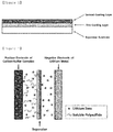
- the present invention provides a separator for lithium-sulfur batteries, which includes a separator substrate, a first coating layer formed on at least one surface of the separator substrate, and a second coating layer formed on the first coating layer.
- the at least one surface of the separator substrate refers to one surface facing a positive electrode or a negative electrode, or both surfaces including the one surface and a surface opposite to the one surface.
- FIG. 1 is a cross-sectional view of a separator for lithium-sulfur batteries according to one exemplary embodiment of the present invention in which a first coating layer and a second coating layer are formed on one surface of a separator substrate.
- the separator substrate is not particularly limited as long as it has an ability to penetrate electrolytes and ions and is typically used in the related art.
- the separator substrate which has low resistant to migration of ions in an electrolyte solution and also has an excellent ability to hold moisture in the electrolyte solution, may be preferred.
- a porous polymer film manufactured from a polyolefin-based polymer may be used alone or as a stack thereof.
- polyethylene or polypropylene may be preferred as the polyolefin-based polymer.
- the first coating layer is formed on at least one surface of the separator substrate, and includes a polydopamine.
- Dopamine in the form of a monomer of the polydopamine is well-known as a neurotransmitter, and a molecule mimicking a 3,4-dihydroxy-lphenylalanine (L-DOPA) molecule found in the Mussels living in the sea.
- L-DOPA 3,4-dihydroxy-lphenylalanine
- polydopamines produced by oxidant-induced self-polymerizations and electrochemical polymerizations of dopamine have covalent catechol and imine functional groups
- the polydopamines may form very strong bonds on solid surfaces such as electrodes or separators of batteries as well as organics such as a biomaterial, a synthetic polymer, and the like, thereby making it possible to perform surface reformation and surface modification and form self-assembled multilayers, nanocomposite thin films, and the like.
- the catechol functional group of dopamine is easily oxidized in the presence of oxygen, and self-polymerized to form polydopamine thin films having varying thicknesses.
- Dopamine that is an environmentally friendly and easily available organic substance is self-polymerized in a buffer solution of approximately pH 8.5, and a polydopamine formed through this process is very highly reactive so that new bonds can be easily formed on surfaces of the polydopamine. Also, because the polydopamine can be self-polymerized at room temperature, the polydopamine has an advantage in that the coating may be possible without any additional reagents or equipment, resulting in reduced manufacturing costs and excellent process efficiency.
- the polydopamine may be thinly and uniformly coated as a material having a high adhesion.
- a polydopamine coating layer may activate an electrode reaction and also prevent the diffusion of a lithium polysulfide because lithium ions are easily diffused in an electrolyte solution and the polydopamine coating layer does not permeate a lithium polysulfide as well.
- the hydrophobic separator substrate may be subjected to surface reformation.
- the first coating layer may be formed to a thickness of 0.1 to 100 ⁇ m, preferably 0.5 to 50 ⁇ m, and more preferably 1 to 10 ⁇ m.
- a rang e of the thickness is less than the lower limit, effects on the diffusion of lithium ions and the adsorption of the lithium polysulfide, and an effect on the adhesion of the second coating layer including the water-soluble material may be poor.
- a range of the thickness is greater than the upper limit, problems regarding the electrode performance due to the poor diffusion of lithium ions may be caused, and the electrode may unnecessarily become thicker.
- the second coating layer is formed on the first coating layer, and includes a lithium-substituted water-soluble polymer.
- the water-soluble polymer may be easily separated without any strong adhesion due to different properties when the hydrophobic separator substrate is directly coated with the water-soluble polymer.
- a first coating layer including the polydopamine serves to compensate for these problems, and the water-soluble polymer may be strongly adhered onto the first coating layer.
- the separator substrate coated with the water-soluble polymer may be easily compatible with an electrolyte solution, the separator substrate may reduce resistance that may be caused by addition of the coating layer onto the separator.
- the water-soluble polymer has an effect of suppressing the polysulfide diffusion, the polysulfide generated in the positive electrode may be accumulated on a surface of the negative electrode to prevent a problem of eluding sulfur.
- the water-soluble polymer is not particularly limited as long as it is coated onto the separator substrate to have the aforementioned functionality.
- the water-soluble polymer is formed through polymerization of a monomer containing one or more carboxyl groups (-COOH), and contains the carboxyl groups.
- the monomer is mainly polymerized via multiple bonds other than carboxyl groups. Therefore, the water-soluble polymer may contain a number of carboxyl groups in the polymer, depending on a degree of polymerization thereof.
- the carboxyl groups contained in the water-soluble polymer may be substituted with lithium.
- a polyacrylic acid may be preferred as the water-soluble polymer.
- the water-soluble polymer may have a structure in which the carboxyl groups are substituted with lithium.
- the separator substrate When the separator substrate is directly coated with the water-soluble polymer, an effect of suppressing the diffusion of the lithium polysulfide may be expected as described above, but water-soluble polymer films are compactly formed, which makes it difficult to pass lithium ions therethrough.
- the separator substrate When lithium is substituted in the water-soluble polymer, the separator substrate may reduce resistance that may be caused due to the aforementioned problems.
- Lithium may be substituted with hydrogen in the water-soluble polymer. In this case, because hydrogen contained in an acidic functional group is easily detached from a polymer, it may be easily substituted with lithium.
- Carboxylic acid may be preferred as the acidic functional group.
- the water-soluble polymer may have at least 50%, preferably at least 70%, of hydrogen substituted with lithium with respect to the carboxyl groups.
- the lithium ions may be readily transported through the second coating layer, resulting in increased resistance by the separator.
- the second coating layer may be formed to a thickness of 0.1 to 100 ⁇ m, preferably 0.5 to 50 ⁇ m, and more preferably 1 to 10 ⁇ m.
- a range of the thickness is less than the lower limit, an effect of suppressing the diffusion of the lithium polysulfide in the separator may be poor.
- a range of the thickness is greater than the upper limit, conductivity of the lithium ions in the separator may be significantly reduced.
- the aforementioned separator is manufactured by a method which includes (1) mixing dopamine and a solvent to prepare a first composition, (2) coating a separator substrate with the first composition to form a first coating layer, (3) mixing a water-soluble polymer and a lithium precursor to prepare a second composition, and (4) coating the first coating layer with the second composition to form a second coating layer.
- the dopamine in the solvent is self-polymerized to form a polydopamine.
- the composition is used to have the most comprehensive meaning as a material consisting of one or more components.
- the method of manufacturing a separator for lithium-sulfur batteries will be described in detail.
- dopamine and a solvent are mixed to prepare a first composition.
- the solvent may uniformly disperse dopamine, and thus a material that may be easily evaporated to dryness may be used as the solvent.
- the dopamine dissolved in the solvent may be self-polymerized so that the dopamine can be converted into a polydopamine.
- the polydopamine formed through the self-polymerization is very highly reactive and form new bonds on a surface thereof, the polydopamine has excellent adhesion.
- An additional binder is not required during the polydopamine coating due to the adhesion of such a polydopamine itself.
- acetonitrile, methanol, ethanol, tetrahydrofuran, water or isopropyl alcohol may be used as the solvent. More particularly, water may be preferred as the solvent.
- the water may be used in the form of a buffer solution.
- an oxidant such as NaIO 4 , piperidine, or the like may be used to enhance a formation rage of the polydopamine coating layer.
- a concentration of the polydopamine in the first composition may be preferably in a range of 1 to 100 mM.
- the mixing to prepare the first composition may be performed by a conventional method using a conventional mixing machine, for example a paste mixer, high-shear mixer, homo-mixer, and the like.
- the separator substrate is coated with the first composition prepared by the aforementioned method to form a first coating layer.
- a wet coating method is used as a method of coating the first composition, but the present invention is not particularly limited thereto.
- the method may be a method such as doctor blade coating, dip coating, gravure coating, slit die coating, spin coating, comma coating, bar coating, reverse roll coating, screen coating, or cap coating. More particularly, dip coating may be preferred as the method.
- a drying process may be performed. In the drying process, the drying temperature and time may vary depending on the solvents used. Particularly, the drying process may be preferably performed within 24 hours in a vacuum oven at 60 to 80 °C to prevent deformation of the separator and the coating layer.
- a water-soluble polymer and a lithium precursor are mixed to prepare a second composition.
- the mixing is preferably performed in an aqueous solution state, and a compound having high solubility in water is preferred as the lithium precursor to facilitate substitution of lithium in the water-soluble polymer.
- a concentration of lithium in the solution may be very low.
- a method of substituting some of dissolved lithium ions, drying the lithium ions and re-dissolving the lithium ions to substitute the lithium ions may be used.
- the temperature conditions are not particularly limited, but it is desirable to perform the mixing under temperature conditions in which the solution is heated to a temperature greater than or equal to room temperature in consideration of the efficiency of lithium substitution.
- the mixing may be performed at a condition of a temperature of 50 to 80 °C.
- the water-soluble polymer is as described above, and the lithium precursor is not particularly limited as long as it is an inorganic compound containing lithium atoms, which lithium ions thereof can substitute hydrogen in the water-soluble polymer.
- the inorganic compound may be Li 2 O, Li 2 O 2 , LiOH, LiCl, LiBr, LiI, LiClO 4 , Li 2 SO 4 , LiNO 3 , or a combination thereof.
- Amounts of the water-soluble polymer and the lithium precursor to be mixed may be properly adjusted within a range capable of substituting more than 50 mol% of the water-soluble polymer with lithium with respect to the carboxyl groups, as described above.
- the lithium precursor may be introduced and mixed at 50 to 200 mol%, preferably 50 to 100 mol% with respect to the carboxyl groups of the water-soluble polymer.
- the lithium precursor When the lithium precursor is introduced at 100 mol% or more, almost all hydrogen ions present in the carboxyl groups of the water-soluble polymer may be substituted with lithium. As a result, the remaining lithium precursor may be present in a crystal from on the second coating layer. However, when an amount of the lithium precursor is greater than 200 mol%, the performance of the battery may be rather degraded.
- the first coating layer is coated with the resulting second composition to form a second coating layer.
- the coating of the second composition may be performed in the same manner as in the aforementioned method of coating the first composition.
- a drying process may be performed in a process of forming the second coating layer.
- the drying temperature and time may vary depending on the water-soluble polymers used. Particularly, the drying process may be preferably performed within 24 hours in a vacuum oven at 60 to 80 °C to prevent deformation of the separator and coating layer.
- the coating layer may be formed on one or both surfaces of the separator substrate.
- the aforementioned separator for lithium-sulfur batteries is applied to a lithium-sulfur battery.
- the lithium-sulfur battery includes the separator, a positive electrode, a negative electrode, and an electrolyte solution, and the separator is interposed between the positive electrode and the negative electrode.
- the separator is configured so that the second coating layer is interposed between the positive electrode and the negative electrode to face the negative electrode.
- FIG. 2 is a cross-sectional view of a lithium-sulfur battery in which the first coating layer and the second coating layer are formed only on one surface of the separator substrate.
- the positive electrode includes elemental sulfur (S 8 ), a sulfur-based compound or a mixture thereof as a positive electrode active material.
- a sulfur material used as the positive electrode active material has no electrical conductivity when used alone, the sulfur material is blended with a conductive material and applied.
- the conductive material may be porous. Therefore, conductive materials may be used as the conductive material without limitation as long as they can have porosity and conductivity.
- a carbon-based material having the porosity may be used. Carbon black, graphite, graphene, activated charcoal, carbon fibers, carbon nanotubes (CNT), and the like may be used as the carbon-based material.
- metallic fibers such as metal meshes, and the like; metallic powders such as copper, silver, nickel, aluminum, and the like; or organic conductive materials such as polyphenylene derivatives, and the like may also be used.
- the conductive materials may be used alone or in a combination thereof.
- a material capable of reversibly intercalating or deintercalating lithium ions (Li + ), a material capable of reacting with lithium ions to reversibly form a lithium-containing compound, a lithium metal, or a lithium alloy may be used as the negative electrode active material.
- the material capable of reversibly intercalating or deintercalating lithium ions (Li + ) may be crystalline carbon, amorphous carbon, or a mixture thereof.
- the material capable of reacting with lithium ions (Li + ) to reversibly form a lithium-containing compound may, for example, be tin oxide, titanium nitrate, or silicone.
- the lithium alloy may, for example, an alloy of lithium (Li) and a metal selected from the group consisting of sodium (Na), potassium (K), rubidium (Rb), cesium (Cs), francium (Fr), beryllium (Be), magnesium (Mg), calcium (Ca), strontium (Sr), barium (Ba), radium (Ra), aluminum(Al), silicon (Si), and tin (Sn).
- a metal selected from the group consisting of sodium (Na), potassium (K), rubidium (Rb), cesium (Cs), francium (Fr), beryllium (Be), magnesium (Mg), calcium (Ca), strontium (Sr), barium (Ba), radium (Ra), aluminum(Al), silicon (Si), and tin (Sn).
- sulfur used as the positive electrode active material may be converted into an inactive material, which may then be attached to a surface of a lithium negative electrode.
- inactive sulfur refers to sulfur which can no longer participate in an electrochemical reaction of the positive electrode because it is subjected to various electrochemical or chemical reactions, and the inactive sulfur formed on the surface of the lithium negative electrode has an advantage in that it serves as a protective layer of the lithium negative electrode.
- the electrolyte solution includes a lithium salt and a non-aqueous organic solvent.
- the lithium salt of the present invention is a material that is easily dissolved in the non-aqueous organic solvent, and may, for example, include one or more selected from the group consisting of LiCl, LiBr, LiI, LiClO 4 , LiBF 4 , LiB 10 Cl 10 , LiB(Ph) 4 , LiPF 6 , LiCF 3 SO 3 , LiCF 3 CO 2 , LiAsF 6 , LiSbF 6 , LiAlCl 4 , LiSO 3 CH 3 , LiSO 3 CF 3 , LiSCN, LiC(CF 3 SO 2 ) 3 , LiN(CF 3 SO 2 ) 2 , LiNO 3 , LiFSI, chloroborane lithium, lower aliphatic lithium carbonate, lithium tetraphenylborate, and imide.
- a concentration of the lithium salt may be in a 0.2 to 4 M, particularly 0.3 to 2 M, and more particularly 0.3 to 1.5 M, depending on various factors such as an exact composition of the electrolyte mixture, the solubility of the salt, the conductivity of a salt to be dissolved, the charge/discharge conditions of a battery, the working temperature, and other factors known in the field of lithium batteries.
- the lithium salt is used at a concentration of less than 0.2 M, the performance of an electrolyte may be degraded due to a drop in conductivity of the electrolyte.
- the lithium salt is used at a concentration of greater than 4 M, mobility of lithium ions (Li + ) may be reduced due to an increase in viscosity of the electrolyte.
- the non-aqueous organic solvent should serve to dissolve the lithium salt sufficiently.
- aprotic organic solvents such as N-methyl-2-pyrrolidinone, propylene carbonate, ethylene carbonate, butylene carbonate, dimethyl carbonate, diethyl carbonate, ethyl methyl carbonate, gamma-butyrolactone, 1,2-dimethoxy ethane, 1,2-diethoxy ethane, tetrahydroxy franc, 2-methyl tetrahydrofuran, dimethylsulfoxide, 1,3-dioxolane, 4-methyl-1,3-dioxene, diethyl ether, formamide, dimethyl formamide, dioxolane, acetonitrile, nitromethane, methyl formate, methyl acetate, phosphite triester, trimethoxy methane, dioxolane derivatives, sulforane, methylsulforane, 1,3-dimethyl-2-
- An organic solid electrolyte or an inorganic solid electrolyte may be used instead of the electrolyte solution.
- polyethylene derivatives, polyethylene oxide derivatives, polypropylene oxide derivatives, phosphate ester polymers, polyagitation lysine, polyester sulfide, polyvinyl alcohols, polyvinylidene fluoride, and polymers containing ionic dissociation groups may be used as the organic solid electrolyte.
- nitrides, halides, sulfate, and the like of Li such as Li 3 N, LiI, Li 5 NI 2 , Li 3 N-LiI-LiOH, LiSiO 4 , LiSiO 4 -LiI-LiOH, Li 2 SiS 3 , Li 4 SiO 4 , Li 4 SiO 4 -LiI-LiOH, Li 3 PO 4 -Li 2 S-SiS 2 , and the like may, for example, be used as the inorganic solid electrolyte.
- pyridine triethylphosphite, triethanolamine, cyclic ether, ethylenediamine, n-glyme, hexaphosphoric triamide, nitrobenzene derivatives, sulfur, quinone imine dyes, N-substituted oxazolidinone, N,N-substituted imidazolidine, ethylene glycol dialkyl ether, ammonium salts, pyrrole, 2-methoxy ethanol, aluminum trichloride, or the like may also be added to the electrolyte solution of the present invention.
- the electrolyte solution may further include a halogen-containing solvent such as carbon tetrachloride, ethylene trifluoride, or the like in order to impart incombustibility.
- the electrolyte solution may further include a carbon dioxide gas, and may also further include fluoroethylene carbonate (FEC), propene sultone (PRS), fluoropropylene carbonate (FPC), and the like in order to improve high-temperature storage characteristics.
- FEC fluoroethylene carbonate
- PRS propene sultone
- FPC fluoropropylene carbonate
- a stack-type electrode assembly may be manufactured by interposing a separator between a positive electrode plate and a negative electrode plate and stacking the separator.
- the positive electrode plate and the negative electrode plate are prepared by cutting the aforementioned positive electrode and negative electrode to predetermined sizes, respectively, and the separator is cut to a predetermined size corresponding to those of the positive electrode plate and the negative electrode plate.
- a stack- and folding-type electrode assembly may be manufactured by arranging two or more positive electrode plates and negative electrode plates on a separator sheet, or arranging two or more unit cells, which are stacked with separators interposed between the two or more positive electrode plates and negative electrode plates, on a separator sheet so that a positive electrode and negative electrode face each other with separator sheets interposed therebetween, and winding the separator sheet, or bending the separator sheet to a size corresponding to a size of an electrode plate or a unit cell.
- a battery pack including the aforementioned lithium-sulfur battery may be used as a power source for electric vehicles (EVs), hybrid electric vehicles (HEVs), plug-in hybrid electric vehicles (PHEVs), power storage systems, and the like.
- EVs electric vehicles
- HEVs hybrid electric vehicles
- PHEVs plug-in hybrid electric vehicles
- power storage systems and the like.
- Dopamine (dopamine hydrochloride commercially available from Sigma-Aldrich) was dissolved in a basic buffer solution (pH 8.5) to prepare a polydopamine solution (a first composition) at a concentration of approximately 10 mM.
- a polyethylene film having a thickness of approximately 20 ⁇ m was dipped in the polydopamine solution thus prepared, and then dried at approximately 60 °C to form a first coating layer having a thickness of approximately 1 ⁇ m on the polyethylene film.
- An aqueous solution including approximately 1% by weight of polyacrylic acid was prepared, and LiOH was dissolved in the aqueous solution of polyacrylic acid so that COOH of the polyacrylic acid and lithium were present in a molar ratio of 1:1, thereby preparing a solution for forming a second coating layer (a second composition).
- the aforementioned second composition was prepared at a condition of a temperature of approximately 70 °C, and then cooled to room temperature after the second composition was prepared.
- the solution was applied onto a polyethylene film having the first coating layer prepared by the aforementioned method using a Mayer bar, and then dried at approximately 60 °C to form a second coating layer having a thickness of approximately 1 ⁇ m on the first coating layer.
- a degree of lithium substitution was measured by means of pH. The results of determination showed that almost all of the added lithium substituted hydrogen present in COOH of the polyacrylic acid.
- a positive electrode, a negative electrode, and an electrolyte solution were prepared as follows, and assembled with the separator prepared by the aforementioned method to manufacture a lithium-sulfur battery.
- a positive electrode active material which was prepared by mixing sulfur and carbon nanotubes (CNTs) at a weight ratio of 7:3, 5% by weight of carbon nanofibers as a conductive material, and 10% by weight of a binder
- Lithium foil having a thickness of approximately 35 ⁇ m was used as the negative electrode.
- a lithium-sulfur battery was manufactured in the same manner as in Example 1, except that, upon formation of the second coating layer, LiOH was dissolved in an aqueous solution including 1% by weight of polyacrylic acid so that COOH of the polyacrylic acid and lithium were present in a molar ratio of 1:0.5, thereby preparing a solution for forming a second coating layer.
- a lithium-sulfur battery was manufactured in the same manner as in Example 1, except that, upon formation of the second coating layer, LiOH was dissolved in an aqueous solution including 1% by weight of polyacrylic acid so that COOH of the polyacrylic acid and lithium were present in a molar ratio of 1:2, thereby preparing a solution for forming a second coating layer.
- a lithium-sulfur battery was manufactured in the same manner as in Example 1, except that a polyethylene film having a thickness of approximately 20 ⁇ m was used as the separator without forming a first coating layer and a second coating layer.
- a lithium-sulfur battery was manufactured in the same manner as in Example 1, except that a separator in which only a first coating layer was formed on a polyethylene film having a thickness of approximately 20 ⁇ m was used without forming a second coating layer.
- a lithium-sulfur battery was manufactured in the same manner as in Example 1, except that a second coating layer was formed using an aqueous solution including 1% by weight of polyacrylic acid without mixing LiOH upon formation of the second coating layer.
- a lithium-sulfur battery was manufactured in the same manner as in Example 1, except that, upon formation of the second coating layer, LiOH was dissolved in an aqueous solution including 1% by weight of polyacrylic acid so that COOH of the polyacrylic acid and lithium were present in a molar ratio of 1:3, thereby preparing a solution for forming a second coating layer.
- a lithium-sulfur battery was manufactured in the same manner as in Example 1, except that, upon formation of the second coating layer, LiOH was dissolved in an aqueous solution including 1% by weight of polyacrylic acid so that COOH of the polyacrylic acid and lithium were present in a molar ratio of 1:4, thereby preparing a solution for forming a second coating layer.
- a lithium-sulfur battery was manufactured in the same manner as in Example 1, except that, upon formation of the second coating layer, LiOH was dissolved in an aqueous solution including 1% by weight of polyacrylic acid so that COOH of the polyacrylic acid and lithium were present in a molar ratio of 1:5, thereby preparing a solution for forming a second coating layer.
- a lithium-sulfur battery was manufactured in the same manner as in Example 1, except that heparin was used instead of the polyacrylic acid upon formation of the second coating layer.
- FIG. 3 A profile of potentials and specific capacities measured by discharging the respective lithium-sulfur batteries manufactured in Example 1 and Comparative Examples 1 and 2 at 0.1 C is shown in FIG. 3 .
- FIG. 3 it can be seen that there was no overvoltage in Comparative Example 1 in which the first coating layer and the second coating layer were not coated, as well as Comparative Example 2 in which only the first coating layer was coated and Examples in which the first coating layer and the second coating layer (a lithium-substituted polyacrylic acid) were coated together.
- FIG. 4 A profile of potentials and specific capacities measured by discharging the respective lithium-sulfur batteries prepared in Example 1 and Comparative Examples 1 to 3 at 0.1 C is shown in FIG. 4 .
- FIG. 4 it can be seen that cells were not driven due to high resistance of the coating layer in the case of Comparative Example 3 in which the polyacrylic acid not substituted with lithium was used as the second coating layer.
- Each of the lithium-sulfur batteries manufactured in Example 1 and Comparative Examples 1 and 2 was changed/discharged for 2.5 cycles at 0.1 C/0.1 C (changing/discharging) and 3 cycles at 0.2 C/0.2 C (changing/discharging), and then repeatedly changed/discharged for cycles at 0.3 C/0.3 C (changing/discharging) to measure discharge capacity and Coulombic efficiency of each of the batteries per cycle.
- the results are shown in FIG. 5 . Referring to FIG.
- Comparative Example 2 in which only the first coating layer was formed showed lifespan characteristics similar to Comparative Example 1 in which the first coating layer and the second coating layer were not coated, but that Example 1 including all the first coating layer and the second coating layer had remarkably improved lifespan characteristics, compared to Comparative Examples 1 and 2.
- Each of the lithium-sulfur batteries manufactured in Example 1 and Comparative Examples 1 and 2 was changed/discharged for 2.5 cycles at 0.1 C/0.1 C (changing/discharging) and 3 cycles at 0.2 C/0.2 C (changing/discharging), and then repeatedly changed/discharged for cycles at 0.3 C/0.5 C (changing/discharging) to measure discharge capacity and Coulombic efficiency of each of the batteries per cycle.
- the results are shown in FIG. 6 . Referring to FIG. 6 , unlike the results of FIG.
- Comparative Example 2 in which only the first coating layer was formed showed lifespan characteristics significantly lower than Comparative Example 1 in which the first coating layer and the second coating layer were not coated, but that Example 1 including all the first coating layer and the second coating layer still had remarkably improved lifespan characteristics, compared to Comparative Examples 1 and 2.
- Example 2 Each of the lithium-sulfur batteries manufactured in Example 2 and Comparative Example 1 was changed/discharged for 2.5 cycles at 0.1 C/0.1 C (changing/discharging) and 3 cycles at 0.2 C/0.2 C (changing/discharging), and then repeatedly changed/discharged for cycles at 0.3 C/0.5 C (changing/discharging) to measure discharge capacity and Coulombic efficiency of each of the batteries per cycle.
- the results are shown in FIG. 7 .
- FIG. 7 it can be seen that Example 2 in which a second coating layer coated with the polyacrylic acid with which approximately 50% of lithium ions were substituted was used as the second coating layer had improved lifespan characteristics, compared to Comparative Example 1 in which the first coating layer and the second coating layer were not coated.
- Each of the lithium-sulfur batteries manufactured in Examples 1 and 3 to 6 and Comparative Examples 1 and 2 was changed/discharged for 2.5 cycles at 0.1 C/0.1 C (changing/discharging), and then repeatedly changed/discharged for cycles at 0.3 C/0.5 C (changing/discharging) to measure discharge capacity and Coulombic efficiency of each of the batteries per cycle.
- the result values calculated by limiting the measured capacities to 650 mAh/g are shown in FIG. 8 . Referring to FIG. 8 , it can be seen that the lifespan characteristics of the batteries were rather degraded when the lithium precursor was introduced at a 3-fold molar ratio or more with respect to the COOH of the polyacrylic acid (Comparative Examples 4 to 6).
- Example 9 Each of the lithium-sulfur batteries manufactured in Example 1 and Comparative Example 7 was changed/discharged for 2.5 cycles at 0.1 C/0.1 C (changing/discharging), and then repeatedly changed/discharged for cycles at 0.3 C/0.5 C (changing/discharging) to measure discharge capacity and Coulombic efficiency of each of the batteries per cycle.
- the result values calculated by limiting the measured capacities to 650 mAh/g are shown in FIG. 9 .
- FIG. 9 it can be seen that the lifespan characteristics of the applied batteries were remarkably improved when the second coating layer including the polyacrylic acid was formed on the first coating layer of the polydopamine (Example 1), compared to when the heparin-containing second coating layer was formed (Comparative Example 7).
Landscapes
- Chemical & Material Sciences (AREA)
- Chemical Kinetics & Catalysis (AREA)
- Electrochemistry (AREA)
- General Chemical & Material Sciences (AREA)
- Engineering & Computer Science (AREA)
- Manufacturing & Machinery (AREA)
- Inorganic Chemistry (AREA)
- Cell Separators (AREA)
- Secondary Cells (AREA)
Applications Claiming Priority (2)
| Application Number | Priority Date | Filing Date | Title |
|---|---|---|---|
| KR1020170138965A KR102244908B1 (ko) | 2017-10-25 | 2017-10-25 | 리튬-황 전지용 분리막 및 이를 포함하는 리튬-황 전지 |
| PCT/KR2018/012571 WO2019083257A1 (ko) | 2017-10-25 | 2018-10-23 | 리튬-황 전지용 분리막 및 이를 포함하는 리튬-황 전지 |
Publications (2)
| Publication Number | Publication Date |
|---|---|
| EP3675228A1 true EP3675228A1 (de) | 2020-07-01 |
| EP3675228A4 EP3675228A4 (de) | 2020-11-25 |
Family
ID=66247546
Family Applications (1)
| Application Number | Title | Priority Date | Filing Date |
|---|---|---|---|
| EP18869676.9A Pending EP3675228A4 (de) | 2017-10-25 | 2018-10-23 | Kathode für lithium-schwefel-batterie und lithium-schwefel-batterie damit |
Country Status (6)
| Country | Link |
|---|---|
| US (1) | US11742513B2 (de) |
| EP (1) | EP3675228A4 (de) |
| JP (1) | JP7118138B2 (de) |
| KR (1) | KR102244908B1 (de) |
| CN (1) | CN111279518B (de) |
| WO (1) | WO2019083257A1 (de) |
Families Citing this family (3)
| Publication number | Priority date | Publication date | Assignee | Title |
|---|---|---|---|---|
| CN110690388A (zh) * | 2019-09-18 | 2020-01-14 | 中国科学院金属研究所 | 一种耐热收缩的有机/无机复合型锂电隔膜及其制备方法 |
| KR102287001B1 (ko) | 2020-01-31 | 2021-08-05 | 성균관대학교산학협력단 | 양쪽성 이온을 이용해 표면이 기능화된 분리막 및 이의 제조 방법 |
| CN114824656B (zh) * | 2022-05-07 | 2024-03-01 | 山东仁丰特种材料股份有限公司 | 一种隔膜纸及制备方法、电池 |
Family Cites Families (30)
| Publication number | Priority date | Publication date | Assignee | Title |
|---|---|---|---|---|
| KR100502357B1 (ko) * | 2003-08-29 | 2005-07-20 | 삼성에스디아이 주식회사 | 고분자 필름을 구비한 양극 및 이를 채용한 리튬-설퍼 전지 |
| DE102010018731A1 (de) | 2010-04-29 | 2011-11-03 | Li-Tec Battery Gmbh | Lithium-Schwefel-Batterie |
| KR101261703B1 (ko) | 2011-04-27 | 2013-05-06 | 한국과학기술원 | 리튬이차전지 방전용량 향상방법 이를 위한 분리막 및 그 표면처리방법, 이를 포함하는 리튬이차전지 |
| KR20130012492A (ko) | 2011-07-25 | 2013-02-04 | 한국과학기술원 | 극성용매 및 폴리도파민-코팅 분리막을 포함하는 리튬이차전지 및 분리막 코팅방법 |
| TWI487163B (zh) * | 2012-04-20 | 2015-06-01 | Lg Chemical Ltd | 用於二次電池之電解質及包含其之鋰二次電池 |
| KR20130127201A (ko) | 2012-05-14 | 2013-11-22 | 주식회사 엘지화학 | 다공성 코팅층을 포함하는 세퍼레이터 및 그를 포함하는 전기화학소자 |
| JP2014110079A (ja) * | 2012-11-30 | 2014-06-12 | Nitto Denko Corp | 蓄電デバイス、およびそれに用いる電極並びに多孔質シート |
| KR101488289B1 (ko) * | 2012-12-07 | 2015-01-30 | 현대자동차주식회사 | 부직포 분리막을 이용한 리튬황 배터리 |
| KR20140106292A (ko) * | 2013-02-26 | 2014-09-03 | 삼성에스디아이 주식회사 | 리튬 이차전지용 음극 및 이를 채용한 리튬 이차전지 |
| US8974946B2 (en) | 2013-03-15 | 2015-03-10 | Gm Global Technology Operations | Coating for separator or cathode of lithium—sulfur or silicon—sulfur battery |
| EP3059784B1 (de) * | 2013-10-18 | 2018-07-11 | LG Chem, Ltd. | Trennmembran und lithium-schwefel-batterie damit |
| CN103682216A (zh) | 2013-11-01 | 2014-03-26 | 中国第一汽车股份有限公司 | 一种含有聚多巴胺和陶瓷涂层的锂离子电池隔膜 |
| US10714724B2 (en) * | 2013-11-18 | 2020-07-14 | California Institute Of Technology | Membranes for electrochemical cells |
| US20150188109A1 (en) | 2013-12-30 | 2015-07-02 | Hyundai Motor Company | Separator for lithium-sulfur secondary battery |
| KR101610446B1 (ko) * | 2013-12-30 | 2016-04-07 | 현대자동차주식회사 | 리튬 황 이차전지 분리막 |
| CN104051691B (zh) * | 2014-06-06 | 2017-01-18 | 中国第一汽车股份有限公司 | 一种基于聚多巴胺的改性复合聚合物隔膜的制备方法 |
| EP3152792B1 (de) | 2014-06-06 | 2020-10-21 | Robert Bosch GmbH | Polymerelektrolyt für lithium-schwefel-zelle |
| CN104037380B (zh) * | 2014-06-10 | 2017-02-08 | 中国第一汽车股份有限公司 | 一种基于聚多巴胺的改性聚合物颗粒隔膜的制备方法 |
| CN104051695A (zh) * | 2014-06-20 | 2014-09-17 | 江苏大学 | 锂硫电池用聚合物修饰隔膜、其制备方法及锂硫电池 |
| KR102227974B1 (ko) * | 2014-08-12 | 2021-03-15 | 삼성전자주식회사 | 고분자, 이를 포함하는 바인더 및 음극, 및 상기 음극을 포함하는 리튬전지 |
| KR101915339B1 (ko) | 2014-11-07 | 2018-11-05 | 주식회사 엘지화학 | 분리막, 분리막-전극 복합체 및 이를 포함하는 전기화학소자 |
| US20160164060A1 (en) | 2014-12-05 | 2016-06-09 | Celgard, Llc | Coated separators for lithium batteries and related methods |
| WO2017032304A1 (zh) * | 2015-08-26 | 2017-03-02 | 厦门大学 | 一种改性陶瓷复合隔膜及制造方法 |
| JP2018532992A (ja) | 2015-09-09 | 2018-11-08 | ソマロジック, インコーポレイテッドSomaLogic, Inc. | 個別化薬物治療計画の開発方法、及びプロテオミックプロファイルに基づく標的薬物開発 |
| KR102459626B1 (ko) * | 2015-11-26 | 2022-10-28 | 삼성전자주식회사 | 수용성 폴리아믹산 및 이의 제조방법, 상기 폴리아믹산을 포함하는 리튬 전지용 바인더 조성물 및 이를 이용하여 제조된 리튬 전지 |
| KR102038543B1 (ko) * | 2016-01-28 | 2019-10-30 | 주식회사 엘지화학 | 폴리도파민을 포함하는 복합 코팅층이 형성된 리튬-황 전지용 분리막, 이의 제조방법 및 이를 포함하는 리튬-황 전지 |
| CN106784538A (zh) * | 2017-01-24 | 2017-05-31 | 厦门大学 | 聚多巴胺陶瓷隔膜的喷涂制备方法及其在锂离子电池中的应用 |
| CN109096671A (zh) * | 2017-08-09 | 2018-12-28 | 浙江林奈新能源有限公司 | 聚丙烯酸锂及其他薄膜材料及其他用途 |
| KR20190027601A (ko) * | 2017-09-07 | 2019-03-15 | 현대자동차주식회사 | 전극용 슬러리, 이를 포함하는 전극 및 리튬 이차전지 |
| KR101840458B1 (ko) | 2017-11-27 | 2018-03-20 | 주식회사 경신 | 버스바 고정용 스터드 클립 |
-
2017
- 2017-10-25 KR KR1020170138965A patent/KR102244908B1/ko active IP Right Grant
-
2018
- 2018-10-23 EP EP18869676.9A patent/EP3675228A4/de active Pending
- 2018-10-23 WO PCT/KR2018/012571 patent/WO2019083257A1/ko unknown
- 2018-10-23 US US16/646,059 patent/US11742513B2/en active Active
- 2018-10-23 JP JP2020513507A patent/JP7118138B2/ja active Active
- 2018-10-23 CN CN201880067143.0A patent/CN111279518B/zh active Active
Also Published As
| Publication number | Publication date |
|---|---|
| CN111279518B (zh) | 2022-11-29 |
| EP3675228A4 (de) | 2020-11-25 |
| US20200280038A1 (en) | 2020-09-03 |
| CN111279518A (zh) | 2020-06-12 |
| US11742513B2 (en) | 2023-08-29 |
| JP7118138B2 (ja) | 2022-08-15 |
| WO2019083257A1 (ko) | 2019-05-02 |
| JP2020532841A (ja) | 2020-11-12 |
| KR102244908B1 (ko) | 2021-04-26 |
| KR20190045969A (ko) | 2019-05-07 |
Similar Documents
| Publication | Publication Date | Title |
|---|---|---|
| EP3312906B1 (de) | Separatorfilm mit einer kompositbeschichtung mit polydopamin für eine lithium-schwefel-batterie, verfahren zu dessen herstellung und lithium-schwefel-batterie dasselbe umfassend | |
| EP3312139B1 (de) | Selbstassemblierter verbundstoff aus kohlenstoffnitrid und graphenoxid, herstellungsverfahren dafür, positivelektrode mit anwendung desselben und lithium-schwefel-batterie damit | |
| KR101336070B1 (ko) | 에너지 밀도 특성이 향상된 고 에너지 리튬 이차전지 | |
| KR101336079B1 (ko) | 에너지 밀도 특성이 향상된 고에너지 밀도의 리튬 이차전지 | |
| KR101336082B1 (ko) | 출력 밀도 특성이 향상된 고출력의 리튬 이차전지 | |
| EP2892104B1 (de) | Elektrodenanordnung für schwefel-lithium-ionen-batterie und schwefel-lithium-ionen-batterie damit | |
| KR101336674B1 (ko) | 에너지 밀도 특성이 향상된 고에너지 밀도의 리튬 이차전지 | |
| KR101336078B1 (ko) | 출력 밀도 특성이 향상된 고출력의 리튬 이차전지 | |
| US11742513B2 (en) | Separator for lithium-sulfur batteries and lithium-sulfur battery comprising the same | |
| KR101588624B1 (ko) | 전극 전도도가 향상된 전극 및 이의 제조방법 | |
| EP3624223B1 (de) | Lithium-schwefel-batterie | |
| KR102229446B1 (ko) | 리튬-황 전지용 분리막 및 이를 포함하는 리튬-황 전지 | |
| KR20140070381A (ko) | 아크릴로니트릴-아크릴산 공중합체를 포함하는 양극용 조성물, 이의 제조방법 및 이를 포함하는 리튬 이차 전지 |
Legal Events
| Date | Code | Title | Description |
|---|---|---|---|
| STAA | Information on the status of an ep patent application or granted ep patent |
Free format text: STATUS: THE INTERNATIONAL PUBLICATION HAS BEEN MADE |
|
| PUAI | Public reference made under article 153(3) epc to a published international application that has entered the european phase |
Free format text: ORIGINAL CODE: 0009012 |
|
| STAA | Information on the status of an ep patent application or granted ep patent |
Free format text: STATUS: REQUEST FOR EXAMINATION WAS MADE |
|
| 17P | Request for examination filed |
Effective date: 20200325 |
|
| AK | Designated contracting states |
Kind code of ref document: A1 Designated state(s): AL AT BE BG CH CY CZ DE DK EE ES FI FR GB GR HR HU IE IS IT LI LT LU LV MC MK MT NL NO PL PT RO RS SE SI SK SM TR |
|
| AX | Request for extension of the european patent |
Extension state: BA ME |
|
| A4 | Supplementary search report drawn up and despatched |
Effective date: 20201022 |
|
| RIC1 | Information provided on ipc code assigned before grant |
Ipc: H01M 10/052 20100101ALI20201016BHEP Ipc: H01M 2/16 20060101AFI20201016BHEP |
|
| DAV | Request for validation of the european patent (deleted) | ||
| DAX | Request for extension of the european patent (deleted) | ||
| RAP1 | Party data changed (applicant data changed or rights of an application transferred) |
Owner name: LG ENERGY SOLUTION LTD. |
|
| RAP3 | Party data changed (applicant data changed or rights of an application transferred) |
Owner name: LG ENERGY SOLUTION, LTD. |
|
| REG | Reference to a national code |
Ref country code: DE Ref legal event code: R079 Free format text: PREVIOUS MAIN CLASS: H01M0002160000 Ipc: H01M0010052000 |
|
| RIC1 | Information provided on ipc code assigned before grant |
Ipc: H01M 50/457 20210101ALI20240424BHEP Ipc: H01M 50/451 20210101ALI20240424BHEP Ipc: H01M 50/414 20210101ALI20240424BHEP Ipc: H01M 50/403 20210101ALI20240424BHEP Ipc: H01M 10/052 20100101AFI20240424BHEP |