EP3672073B1 - Transkonduktorschaltung mit einstellbarer vorspannung - Google Patents
Transkonduktorschaltung mit einstellbarer vorspannung Download PDFInfo
- Publication number
- EP3672073B1 EP3672073B1 EP18214610.0A EP18214610A EP3672073B1 EP 3672073 B1 EP3672073 B1 EP 3672073B1 EP 18214610 A EP18214610 A EP 18214610A EP 3672073 B1 EP3672073 B1 EP 3672073B1
- Authority
- EP
- European Patent Office
- Prior art keywords
- node
- current path
- current
- signal
- transistor
- Prior art date
- Legal status (The legal status is an assumption and is not a legal conclusion. Google has not performed a legal analysis and makes no representation as to the accuracy of the status listed.)
- Active
Links
Images


Classifications
-
- H—ELECTRICITY
- H03—ELECTRONIC CIRCUITRY
- H03F—AMPLIFIERS
- H03F3/00—Amplifiers with only discharge tubes or only semiconductor devices as amplifying elements
- H03F3/45—Differential amplifiers
- H03F3/45071—Differential amplifiers with semiconductor devices only
- H03F3/45076—Differential amplifiers with semiconductor devices only characterised by the way of implementation of the active amplifying circuit in the differential amplifier
- H03F3/45475—Differential amplifiers with semiconductor devices only characterised by the way of implementation of the active amplifying circuit in the differential amplifier using IC blocks as the active amplifying circuit
-
- H—ELECTRICITY
- H03—ELECTRONIC CIRCUITRY
- H03F—AMPLIFIERS
- H03F3/00—Amplifiers with only discharge tubes or only semiconductor devices as amplifying elements
- H03F3/45—Differential amplifiers
- H03F3/45071—Differential amplifiers with semiconductor devices only
- H03F3/45076—Differential amplifiers with semiconductor devices only characterised by the way of implementation of the active amplifying circuit in the differential amplifier
- H03F3/45179—Differential amplifiers with semiconductor devices only characterised by the way of implementation of the active amplifying circuit in the differential amplifier using MOSFET transistors as the active amplifying circuit
- H03F3/45197—Pl types
-
- H—ELECTRICITY
- H03—ELECTRONIC CIRCUITRY
- H03F—AMPLIFIERS
- H03F3/00—Amplifiers with only discharge tubes or only semiconductor devices as amplifying elements
- H03F3/45—Differential amplifiers
- H03F3/45071—Differential amplifiers with semiconductor devices only
- H03F3/45479—Differential amplifiers with semiconductor devices only characterised by the way of common mode signal rejection
- H03F3/45632—Differential amplifiers with semiconductor devices only characterised by the way of common mode signal rejection in differential amplifiers with FET transistors as the active amplifying circuit
- H03F3/45636—Differential amplifiers with semiconductor devices only characterised by the way of common mode signal rejection in differential amplifiers with FET transistors as the active amplifying circuit by using feedback means
- H03F3/45641—Measuring at the loading circuit of the differential amplifier
- H03F3/45659—Controlling the loading circuit of the differential amplifier
-
- H—ELECTRICITY
- H03—ELECTRONIC CIRCUITRY
- H03F—AMPLIFIERS
- H03F3/00—Amplifiers with only discharge tubes or only semiconductor devices as amplifying elements
- H03F3/45—Differential amplifiers
- H03F3/45071—Differential amplifiers with semiconductor devices only
- H03F3/45479—Differential amplifiers with semiconductor devices only characterised by the way of common mode signal rejection
- H03F3/45632—Differential amplifiers with semiconductor devices only characterised by the way of common mode signal rejection in differential amplifiers with FET transistors as the active amplifying circuit
- H03F3/45636—Differential amplifiers with semiconductor devices only characterised by the way of common mode signal rejection in differential amplifiers with FET transistors as the active amplifying circuit by using feedback means
- H03F3/45663—Measuring at the active amplifying circuit of the differential amplifier
- H03F3/45672—Controlling the common source circuit of the differential amplifier
-
- H—ELECTRICITY
- H03—ELECTRONIC CIRCUITRY
- H03F—AMPLIFIERS
- H03F3/00—Amplifiers with only discharge tubes or only semiconductor devices as amplifying elements
- H03F3/45—Differential amplifiers
- H03F3/45071—Differential amplifiers with semiconductor devices only
- H03F3/45479—Differential amplifiers with semiconductor devices only characterised by the way of common mode signal rejection
- H03F3/45632—Differential amplifiers with semiconductor devices only characterised by the way of common mode signal rejection in differential amplifiers with FET transistors as the active amplifying circuit
- H03F3/45636—Differential amplifiers with semiconductor devices only characterised by the way of common mode signal rejection in differential amplifiers with FET transistors as the active amplifying circuit by using feedback means
- H03F3/45681—Measuring at the common source circuit of the differential amplifier
- H03F3/4569—Controlling the common source circuit of the differential amplifier
-
- H—ELECTRICITY
- H03—ELECTRONIC CIRCUITRY
- H03F—AMPLIFIERS
- H03F3/00—Amplifiers with only discharge tubes or only semiconductor devices as amplifying elements
- H03F3/45—Differential amplifiers
- H03F3/45071—Differential amplifiers with semiconductor devices only
- H03F3/45479—Differential amplifiers with semiconductor devices only characterised by the way of common mode signal rejection
- H03F3/45632—Differential amplifiers with semiconductor devices only characterised by the way of common mode signal rejection in differential amplifiers with FET transistors as the active amplifying circuit
- H03F3/45695—Differential amplifiers with semiconductor devices only characterised by the way of common mode signal rejection in differential amplifiers with FET transistors as the active amplifying circuit by using feedforward means
- H03F3/45699—Measuring at the input circuit of the differential amplifier
- H03F3/45708—Controlling the common source circuit of the differential amplifier
-
- H—ELECTRICITY
- H03—ELECTRONIC CIRCUITRY
- H03F—AMPLIFIERS
- H03F3/00—Amplifiers with only discharge tubes or only semiconductor devices as amplifying elements
- H03F3/45—Differential amplifiers
- H03F3/45071—Differential amplifiers with semiconductor devices only
- H03F3/45479—Differential amplifiers with semiconductor devices only characterised by the way of common mode signal rejection
- H03F3/45632—Differential amplifiers with semiconductor devices only characterised by the way of common mode signal rejection in differential amplifiers with FET transistors as the active amplifying circuit
- H03F3/45695—Differential amplifiers with semiconductor devices only characterised by the way of common mode signal rejection in differential amplifiers with FET transistors as the active amplifying circuit by using feedforward means
- H03F3/45699—Measuring at the input circuit of the differential amplifier
- H03F3/45717—Controlling the loading circuit of the differential amplifier
-
- H—ELECTRICITY
- H03—ELECTRONIC CIRCUITRY
- H03F—AMPLIFIERS
- H03F3/00—Amplifiers with only discharge tubes or only semiconductor devices as amplifying elements
- H03F3/45—Differential amplifiers
- H03F3/45071—Differential amplifiers with semiconductor devices only
- H03F3/45479—Differential amplifiers with semiconductor devices only characterised by the way of common mode signal rejection
- H03F3/45632—Differential amplifiers with semiconductor devices only characterised by the way of common mode signal rejection in differential amplifiers with FET transistors as the active amplifying circuit
- H03F3/45695—Differential amplifiers with semiconductor devices only characterised by the way of common mode signal rejection in differential amplifiers with FET transistors as the active amplifying circuit by using feedforward means
- H03F3/4573—Measuring at the common source circuit of the differential amplifier
- H03F3/45739—Controlling the loading circuit of the differential amplifier
-
- H—ELECTRICITY
- H03—ELECTRONIC CIRCUITRY
- H03F—AMPLIFIERS
- H03F2203/00—Indexing scheme relating to amplifiers with only discharge tubes or only semiconductor devices as amplifying elements covered by H03F3/00
- H03F2203/45—Indexing scheme relating to differential amplifiers
- H03F2203/45061—Indexing scheme relating to differential amplifiers the common mode reference signal being taken or deducted from the one or more inputs of the differential amplifier
-
- H—ELECTRICITY
- H03—ELECTRONIC CIRCUITRY
- H03F—AMPLIFIERS
- H03F2203/00—Indexing scheme relating to amplifiers with only discharge tubes or only semiconductor devices as amplifying elements covered by H03F3/00
- H03F2203/45—Indexing scheme relating to differential amplifiers
- H03F2203/45078—Indexing scheme relating to differential amplifiers the common mode signal being taken or deducted from the one or more inputs of the differential amplifier
-
- H—ELECTRICITY
- H03—ELECTRONIC CIRCUITRY
- H03F—AMPLIFIERS
- H03F2203/00—Indexing scheme relating to amplifiers with only discharge tubes or only semiconductor devices as amplifying elements covered by H03F3/00
- H03F2203/45—Indexing scheme relating to differential amplifiers
- H03F2203/45288—Differential amplifier with circuit arrangements to enhance the transconductance
-
- H—ELECTRICITY
- H03—ELECTRONIC CIRCUITRY
- H03F—AMPLIFIERS
- H03F2203/00—Indexing scheme relating to amplifiers with only discharge tubes or only semiconductor devices as amplifying elements covered by H03F3/00
- H03F2203/45—Indexing scheme relating to differential amplifiers
- H03F2203/45366—Indexing scheme relating to differential amplifiers the AAC comprising multiple transistors parallel coupled at their gates only, e.g. in a cascode dif amp, only those forming the composite common source transistor
-
- H—ELECTRICITY
- H03—ELECTRONIC CIRCUITRY
- H03F—AMPLIFIERS
- H03F2203/00—Indexing scheme relating to amplifiers with only discharge tubes or only semiconductor devices as amplifying elements covered by H03F3/00
- H03F2203/45—Indexing scheme relating to differential amplifiers
- H03F2203/45418—Indexing scheme relating to differential amplifiers the CMCL comprising a resistor addition circuit
-
- H—ELECTRICITY
- H03—ELECTRONIC CIRCUITRY
- H03F—AMPLIFIERS
- H03F2203/00—Indexing scheme relating to amplifiers with only discharge tubes or only semiconductor devices as amplifying elements covered by H03F3/00
- H03F2203/45—Indexing scheme relating to differential amplifiers
- H03F2203/45424—Indexing scheme relating to differential amplifiers the CMCL comprising a comparator circuit
-
- H—ELECTRICITY
- H03—ELECTRONIC CIRCUITRY
- H03F—AMPLIFIERS
- H03F2203/00—Indexing scheme relating to amplifiers with only discharge tubes or only semiconductor devices as amplifying elements covered by H03F3/00
- H03F2203/45—Indexing scheme relating to differential amplifiers
- H03F2203/45471—Indexing scheme relating to differential amplifiers the CSC comprising one or more extra current sources
-
- H—ELECTRICITY
- H03—ELECTRONIC CIRCUITRY
- H03F—AMPLIFIERS
- H03F2203/00—Indexing scheme relating to amplifiers with only discharge tubes or only semiconductor devices as amplifying elements covered by H03F3/00
- H03F2203/45—Indexing scheme relating to differential amplifiers
- H03F2203/45491—Indexing scheme relating to differential amplifiers the CSC being a pi circuit and the resistor being implemented by one or more transistors
Definitions
- the disclosure relates to a transconductor circuitry with adaptive biasing of the input transistors of the transconductor circuitry.
- the disclosure further relates to a sensor device comprising a transconductor circuitry with adaptive biasing of its input transistors.
- a sensor device for example a MEMS microphone, to detect a sound pressure impacting on a transducer of the MEMS microphone usually provides an analog output signal which is converted by a subsequent analog-to-digital converter (ADC) stage to a digital signal.
- the ADC may generate a stream of digital values in response to an input signal which depends on the output signal of the sensor device.
- the ADC is usually built with discrete time switched capacitors which require an input voltage.
- a preceding amplifier which is arranged between the MEMS transducer and the ADC must be a voltage buffer or a voltage gain stage.
- a transconductor circuitry which is able to convert the voltage output signal of the capacitive (MEMS-) microphone sensor into a differential current which is applied as input signal to a subsequent continuous time ADC stage.
- the ADC then converts the received output current of the transconductor circuitry to a digital signal.
- WO 2006/125063 A2 shows a transconductor cell with adaptive biasing.
- Silva-Martinez et al.: Design Techniques for High-Performance Full-CMOS OTA-RC Continuous-Time Filters", IEEE Journal of Solid-State Circuits, IEEE Service Center, Piscataway, NJ, USA, vol. 27, no. 7, 1 July 1992 (1992-07-01), pages 993-1001, XP011401880, ISSN: 0018-9200, DOI: 10.1109/JSSC.1992.1068061 , a controlled pair of current sources in a loading circuitry of a pair of input transistors is shown.
- EP 0 534 007 A1 shows a differential amplifier arrangement, where a common mode detecting signal is formed by resistors of a linking current path between current branches to achieve a voltage reference.
- US 7,321,259 B1 shows dynamic offset cancellation techniques for dynamically correcting offsets of a differential amplifier.
- a transconductor circuitry with adaptive biasing that may be used as an interface between a sensor device, for example a sensor device comprising a MEMS sensor, and a subsequent analog-to-digital circuit with continuous time front-end.
- a further desire is to provide a sensor device comprising a sensor, wherein an analog output signal of the sensor is converted into a digital signal by an ADC with continuous time topology.
- transconductor circuitry with adaptive biasing which may be used to convert an output voltage signal from a sensor device, for example a capacitive microphone sensor, into a differential current which can be used as an input signal for a subsequent ADC with continuous time topology is specified in claim 1.
- the transconductor circuitry with adaptive biasing comprises a first input terminal to apply a first input signal, and a second input terminal to apply a second input signal.
- the transconductor circuitry further comprises a first current path including a first transistor and a first controllable current source to adjust a first biasing current of the first transistor in the first current path.
- the first transistor has a control node being coupled to the first input terminal.
- the transconductor circuitry comprises a second current path including a second transistor and a second controllable current source to adjust a second biasing current of the second transistor in the second current path.
- the second transistor has a control node being coupled to the second input terminal.
- the transconductor circuitry further comprises a control circuit being configured to control the first and the second controllable current source in response to at least one of a first potential of a first node of the first current path and a second potential of a second node of the second current path.
- the first node is located between the first transistor and the first controllable current source.
- the second node is located between the second transistor and the second controllable current source.
- the proposed topology of the transconductor circuitry advantageously enables to convert a voltage signal received at the first and second input terminal from a sensor device, for example a sensor device comprising a capacitive microphone sensor, to a proportional output current with high efficiency.
- a sensor device for example a sensor device comprising a capacitive microphone sensor
- the transconductor circuitry has a low current consumption and shows low noise at small signals and, at the same time, still reasonable signal distortion at large signals.
- the control circuit comprises an amplifier having an output node to generate a control signal to control the first and second controllable current source.
- the transconductor circuitry comprises a linking current path being arranged between the first current path and the second current path.
- An input node of the amplifier of the control circuit may be connected to an internal node of the linking current path.
- the configuration of the transconductor circuitry advantageously enables that the control circuit detects a sensing signal, for example a sensing voltage, at the internal node of the linking current path.
- the internal signal is tapped at a center node of the differential transistor pair of the first and second transistor.
- the control circuit is configured to generate the control signal to regulate/adjust the respective biasing current in the first and the second current path in response to the sensing signal.
- the transconductor circuitry advantageously exploits the observation that the sensing signal/sensing voltage at the internal node of the linking current path increases with larger differential input signal applied at the first and second input terminal, as the respective operating point of the first and second transistor shift away from its respective idle point at zero input signal, i.e. a differential input signal having the zero level.
- the sensing signal/sensing voltage at the internal node of the linking current path is therefore a measure of "how non-linear" the differential transistor pair of the first and second transistor has already become, and is used as a control signal/voltage for adaptive biasing.
- the linking current path comprises a first resistive element and a second resistive element.
- the first resistive element is arranged in the linking current path between the first node of the first current path and the internal node of the linking current path.
- the second resistive element is arranged in the linking current path between the second node of the second current path and the internal node of the linking current path.
- the first and the second resistive elements act as degeneration resistors which allow to shift the first and the second potential to the potential at the internal node of the linking current path.
- the control circuit detects the sensing signal/voltage at the internal node of the linking current path, i.e. at the center node of the differential transistor pair of the first and second transistor. Since the sensing signal/voltage at the internal node of the linking current path also increases according to the embodiment of the transconductor circuitry comprising the first and second resistive element, as the respective operating point of the first and second transistor shift away from its respective idle point at zero differential input signal, the transconductor circuitry advantageously uses the sensing signal/voltage as a measure of the degree of non-linearity of the differential transistor pair. The sensing signal/voltage is used by the control circuit as a control signal for adaptive biasing.
- the sensing signal/voltage at the internal node of the linking current path is directly affected by a common mode voltage at the first and second input terminal, i.e. at a respective control node of the first and second transistor
- a reference generator with an auxiliary transistor pair is advantageously introduced in the transconductor circuitry to make the adaptive biasing robust against changes of the common mode voltage.
- the control circuit of the transconductor circuitry comprises a third current path and a fourth current path.
- the third current path includes a third transistor and a constant current source to generate a biasing current of the third transistor in the third current path.
- the third transistor has a control node being coupled to the first input terminal.
- the fourth current path includes a fourth transistor and a second constant current source to generate another biasing current of the fourth transistor in the fourth current path.
- the fourth transistor has a control node being coupled to the second input terminal.
- the amplifier of the control circuit comprises a second input node to apply a reference signal.
- This configuration of the control circuit allows to compare the sensing signal at the internal node with a defined level of the reference signal.
- the second input node of the amplifier of the control circuit to apply the reference signal is coupled to the third and the fourth current path. This means that the reference signal of the amplifier is advantageously changed in response to a third potential at a third node of the third current path and in response to a fourth potential of a fourth node of the fourth current path.
- the third node is located between the third transistor and the first constant current source.
- the fourth node is located between the fourth transistor and the second constant current source.
- the proposed topology of the control circuit advantageously enables to generate the reference signal that moves synchronously with an input common mode voltage at the first and second input terminal of the transconductor circuitry.
- the control circuit thus only detects an increase of the level of the sensing signal caused by the change of the respective operating point of the first and second transistor.
- the control scheme to control the generation of the biasing currents of the first and second transistor is immune against variations of the input common mode voltage.
- the sensor device comprises a transconductor circuitry with adaptive biasing as specified above or defined in any of the claims 1 to 4.
- the transconductor circuitry is configured to generate an output current signal.
- the sensor device further comprises a sensor including a transducer to detect an environmental signal impacting on the transducer.
- the transducer is configured to generate a voltage signal in response to the environmental signal.
- the sensor device further comprises an analog-to-digital converter having an input side to receive the output current signal.
- the analog-to-digital converter is configured to generate a digital output signal in response to the output current signal.
- the transconductor circuitry is connected to the sensor to receive the voltage signal from the sensor at the first and second input terminal of the transconductor circuitry.
- the transconductor circuitry is further connected to the analog-to-digital converter to provide the output current signal to the input side of the analog-to-digital converter.
- the sensor device advantageously enables to use the transconductor circuitry as an interface between the sensor and the analog-to-digital converter.
- the analog-to-digital converter may be designed with continuous time front-end.
- the design of the transconductor circuitry enables to provide the transconductor circuitry with a very high input impedance being larger than 100 GOhm and being smaller than 1 pF to not dampen the sensor signal.
- the design of the transconductor circuitry advantageously enables to provide a defined transconductance for accurate system gain, to provide a linear characteristic up to high signal levels for good distortion (THD) performance and, in the case of a microphone sensor, high acoustic overload point (AOP).
- TDD good distortion
- AOP acoustic overload point
- the transconductor circuitry has a low noise for high system signal-to-noise ratio (SNR), and consume little power particularly if no or little input signals are present.
- FIG. 1 shows a transconductor circuitry 10 with adaptive biasing for better understanding the claimed embodiment, but not covered by the claims, wherein the biasing current is changed in response to a differential input signal.
- the transconductor circuitry comprises an input terminal E10a to apply an input signal inp, and an input terminal E10b to apply an input signal inn.
- the transconductor circuitry 10 further comprises a current path 101 including a transistor 150 and a controllable current source 110 to adjust a first biasing current of the transistor 150.
- the transistor 150 has a control node being coupled to the input terminal E10a.
- the gate terminal of the transistor 150 is coupled to the input terminal E10a of the transconductor circuitry to receive the input signal inp.
- the transconductor circuitry 10 further comprises a current path 102 including a transistor 160 and a controllable current source 120 to adjust a second biasing current of the transistor 160.
- the transistor 160 has a control node being coupled to the input terminal E10b.
- a gate node of the transistor 160 is coupled to the input terminal E10b to receive the input signal inn.
- the transconductor circuitry 10 shown in Figure 1 further comprises a control circuit 200 being configured to control the controllable current sources 110, 120 in response to at least one of a first potential of a node N1 of the current path 101 and a second potential of a node N2 of the current path 102.
- the node N1 of the current path 101 is located between the transistor 150 and the controllable current source 110.
- the node N2 of the current path 102 is located between the transistor 160 and the controllable current source 120.
- the transconductor circuitry 10 comprises an output terminal O10a to generate an output signal outn.
- the output terminal O10a is connected to a drain terminal of the transistor 150.
- the transconductor circuitry 10 further comprises an output terminal O10b to output an output signal outp.
- the output terminal O10b is connected to a drain terminal of the transistor 160.
- the control circuit 200 comprises an amplifier 250 which has an output node 0250 to generate a control signal CS to control the controllable current sources 110 and 120.
- the amplifier 250 may be configured as a transconductance amplifier.
- the amplifier 250 comprises an input node I250a which is coupled to the current paths 101, 102 in a way so that a sensing signal Vx applied at the input node I250a of the amplifier 250 is changed in response to at least one of the first potential of the node N1 and the second potential of the node N2.
- the transconductor circuitry 10 of Figure 1 comprises a linking current path 103 which is arranged between the node N1 of the current path 101 and the node N2 of the current path 102.
- the input node I250a of the amplifier 250 of the control circuit 200 is connected to an internal node N103 of the linking current path 103.
- the control circuit 200 is configured to generate the control signal CS by the amplifier 250 to control the controllable current sources 110, 120 in response to the sensing signal Vx detected at the internal node N103 of the linking current path 103.
- the linking current path 103 may comprise a resistive element 170 and a resistive element 180. Both of the resistive elements 170 and 180 may be configured as a resistor having the same resistance. As shown according to the embodiment of the transconductor circuitry 10 of Figure 1 , the resistive element 170 is connected between the node N1 of the current path 101 and the internal node N103 of the linking current path 103. The resistive element 180 is connected between the node N2 of the current path 102 and the internal node N103 of the linking current path 103.
- the amplifier 250 further comprises an input node I250b to apply a reference signal Vrefx.
- the amplifier 250 is configured to generate the control signal CS in response to the sensing signal Vx and the reference signal Vrefx.
- the current path 101 may include a controllable current source 130.
- the current path 102 may include a controllable current source 140.
- the output terminal O10a is arranged between the transistor 150 and the controllable current source 130.
- the output terminal O10b is arranged between the transistor 160 and the controllable current source 140.
- the control circuit 200 is configured to control the controllable current sources 130 and 140 in response to the first potential of the node N1 of the current path 101 and in response to the second potential of the node N2 of the current path 102.
- the control circuit 200 is configured to generate the control signal CS by the amplifier 250 to control the controllable current sources 110, 120 and the controllable current sources 130, 140 in response to the sensing signal Vx detected at the internal node N103 of the linking current path 103.
- transconductor circuitry 10 shown in Figure 1 works.
- the transconductor circuitry 10 would not comprise the control circuit 200 to control the controllable current sources 110, 120 and optionally the controllable current sources 130 and 140.
- a differential input voltage is applied to the transconductor circuitry 10 by applying a first input signal inp to the input terminal E10a and applying a second input signal inn to the input terminal E10b.
- both of the output terminals O10a, O10b are kept at a constant voltage by a load circuitry coupled to the output terminals O10a, O10b (not shown in Figure 1 ).
- the transistors 150 and 160 respectively change their source current only by a little, leaving their operating point almost constant.
- the differential input voltage is attenuated and transferred to node N1 and node N2 in a reasonably linear way.
- the current flowing in the linking current path 103 is proportional to the differential input voltage. This current is output at the drain nodes of transistors 150 and 160, i.e. at the output terminals O10a and O10b.
- the respective operating point of transistors 150 and 160 changes, because the current flowing through the conductive path of transistors 150 and 160 also changes.
- the respective transconductance of both of the transistors 150 and 160 changes in different ways so that the generated output current at the output terminals no longer depends linearly on the differential input voltage.
- the transconductor circuitry 10 is provided with the control circuit 200 which adjusts the biasing current of the transistors 150 and 160 in response to the differential input signal level.
- the control circuit 200 is configured as a special adaptive biasing circuit which increases the bias current through transistors 150 and 160 depending on the differential input signal voltage applied at the input terminals E10a and E10b.
- the proposed topology of the transconductor circuitry 10 exploits the observation that the sensing signal Vx between the resistive elements 170 and 180 increases gradually as a differential input voltage at the input terminals E10a and E10b increases (with either polarity) which stems from the non-linear behaviour of transistors 150 and 160.
- transistor 160 is turned off completely, and the sensing signal Vx will directly follow the level of the input signal inp with transistor 150 acting as a source follower.
- the level of the sensing signal Vx is therefore a good indicator for the operating points of transistors 150 and 160, reflecting how one of them is losing bias current.
- the sensing signal Vx can be used to gradually steer additional bias current into the circuit to prevent an excessively non-linear transfer characteristic or even the turn-off of transistors 150 or 160.
- control circuit 200 comprising a regulator circuit 250 being embodied as the amplifier 250.
- control circuit 200 is able to simultaneously increase all four currents I1, I2, I3 and I4 generated by the controllable current sources 110, 120, 130 and 140, as the level of the sensing signal Vx increases compared to a level of the reference signal Vrefx
- the undesired non-linear characteristic between the differential input signal and the output current resulting from the changing operating points of transistors 150 and 160 at large differential input signals can be flattened, while at the same time the bias current (and thus the power consumption) at small differential input signals stays small.
- the circuitry does not need a high gain regulation loop with stability issues to regulate the respective current portions I1, I2, I3 and I4 generated by the controllable current sources 110, 120, 130 and 140. Furthermore, any noise contributors of the circuitry are limited to the inherent circuit elements, for example transistors 150, 160, resistive elements 170, 180 and controllable current sources 110, ..., 140 which would have to somehow exist in any such transconductor circuitry.
- FIG. 2 shows a transconductor circuitry 10 with adaptive biasing for better understanding the claimed embodiment, but not covered by the claims, wherein a configuration of the control circuit 200 for generating the reference signal Vrefx is shown in detail.
- the control circuit 200 comprises the regulation circuit 250 being configured as the amplifier 250 to generate the control signal CS to control the controllable current sources 110,..., 140.
- the control circuit 200 comprises a current path 260 comprising a constant current source 261 to generate a constant current I5 in the current path 260 and a level shifting transistor 262.
- a reference signal Vrefcm is applied to a control node of the level shifting transistor 262 and is further applied via a resistor 271 to the input terminal E10a and via a resistor 272 to the input terminal E10b.
- the level shifting transistor 262 matching to transistors 150 and 160, is used to shift down the common mode reference voltage Vrefcm which also serves as a reference for the DC voltage biasing of the two high impedance input nodes E10a and E10b. While theoretically such a circuit topology could be feasible for certain applications that have a constant input common mode voltage, in a MEMS microphone application, it has to be considered that the input common mode voltage at the input terminals E10a and E10b is subject to change, for example directly with the input signals inp and inn if a single-ended topology is used, or as a result of transients on the high voltage MEMS sensor biasing node, and such changes are directly transferred to the internal node N103. As a consequence, the sensing signal Vx is influenced by the common mode voltage, thereby possibly disturbing the operation of the adaptive biasing.
- Figure 3 shows a transconductor circuitry 10 with adaptive biasing for better understanding the claimed embodiment, but not covered by the claims, wherein the control circuit 200 includes another (improved) topology as compared with Figure 2 to generate the reference signal Vrefx.
- the control circuit 200 of the transconductor circuitry 10 of Figure 3 comprises a current path 201 and a current path 202.
- the current path 201 includes a transistor 230 and a constant current source 210 to generate a biasing current of the transistor 230 in the current path 201.
- the transistor 230 has a control node being coupled to the input terminal E10a.
- the current path 202 includes a transistor 240 and a constant current source 220 to generate another biasing current of the transistor 240 in the current path 202.
- the transistor 240 has a control node being coupled to the input terminal E10b.
- the input node I250b of the amplifier 250 is coupled to the current path 201 and the current path 202 so that the reference signal Vrefx is changed in response to a potential of a node N3 of the current path 201 and in response to a potential of a node N4 of the current path 202.
- the node N3 is located in the current path 201 between the transistor 230 and the constant current source 210.
- the node N4 is located in the current path 202 between the transistor 240 and the constant current source 220.
- the control circuit 200 comprises a linking current path 203 being arranged between the node N3 of the current path 201 and the node N4 of the current path 202.
- the input node I250b of the amplifier 250 is connected to an internal node N203 of the linking current path 203.
- the linking current path 203 comprises a resistive element 260 and a resistive element 270 which may both be embodied as a resistor.
- the resistive element 260 is connected between the node N3 of the current path 201 and the internal node N203 of the linking current path 203.
- the resistive element 270 is connected between the node N4 of the current path 202 and the internal node N203 of the linking current path 203.
- the configuration of the control circuit 200 of the transconductor circuitry 10 of Figure 3 uses with the transistors 230 and 240 an auxiliary transistor pair which allows to generate the reference signal Vrefx that moves along with the input common mode voltage at the input terminals E10a and E10b.
- the amplifier stage 250 therefore only detects an increase of the level of the sensing signal Vx resulting from a change of the respective operation point of transistors 150 and 160, while the control circuit is immune against variations of the input common mode voltage. This makes the adaptive biasing scheme of the control circuit topology shown in Figure 3 robust against such variations.
- the transistors 150 and 160 as well as the transistors 230 and 240 may be embodied as transistors of the n-type, for example NMOS transistors, or as transistors of the p-type, for example PMOS transistors. Furthermore, it is also possible that the transistors may be embodied as JFET transistors.
- NMOS transistors advantageously enables to provide transistors with a suitable transconductance and a low area consumption.
- the respective embodiment of the transconductor circuitry shown in Figures 1 to 3 comprise controllable current sources 110, 120, 130 and 140. It has to be noted that, to adjust the biasing current of the transistors 150 and 160, it is sufficient if each of the current paths 101 and 102 only comprises one controllable current source. Assuming the transistors 150 and 160 are of the n-type, for example embodied as NMOS transistors, only the current sources 110 and 120 need to be configured as controllable current sources while keeping the current of the current sources 130 and 140 constant.
- the transistors 150 and 160 are realized as transistors of the p-type, for example embodied as PMOS transistors, it is necessary that only the current sources 130 and 140 are embodied as controllable current sources while keeping the current of the current sources 110 and 120 constant.
- the topology of the transconductor circuitry 10 can be simplified by accepting a variable output common mode current.
- cascode transistors may be provided at the drain nodes of the transistors 150, 160 which allows to improve the output impedance of the transconductor circuitry.
- the illustrated embodiments of the transconductor circuitry 10 shown in Figures 1 to 3 comprise resistive elements 170, 180 in the linking current path 103 and resistive elements 260 and 270 in the linking current path 203.
- the resistive elements 170 and 180 can be removed/set to zero. In this case the nodes N1 and N2 are directly connected.
- the resistive elements 260 and 270 may be removed/set to zero so that the Nodes N3 and N4 are directly connected with each other.
- Such a simplified topology of the transconductor circuitry enables the area consumption of the circuitry to be reduced.
- transconductor circuitries 10 shown in Figures 1 to 3 it is possible to add a deliberate input voltage offset to the amplifier stage 250 of the control circuit 200. This modification advantageously enables to ensure that the control of the adaptive biasing procedure does not start before a certain signal level of the differential input signal is reached.
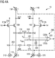
- Figures 4A and 4B show possible implementations to add the input voltage offset to the control circuit 200.
- a current source 281 with a resistor 282 is coupled to the input node I250b, for example the inverting input node, of the amplifier 250.
- the input voltage offset may be added to the control circuit 200 by providing a current source or current sink 283 applied to the internal node N103 between the resistive elements 170 and 180, as illustrated in Figure 4B.
- Figure 4B shows in dashed lines an alternative embodiment to add the input voltage offset to the amplifier stage 250 by providing a current source or current sink 284 applied to the internal node N203 between the resistive elements 260 and 270.
- Figure 4C shows the transconductor circuitry 10 of Figure 3 , wherein a respective constant current source 191, 192, 193 and 194 is connected in parallel to each of the controllable current sources 110, 120, 130 and 140.
- the adding of constant/non-adjustable current sources 191, ..., 194 in parallel to the controllable/adjustable current sources 110, ..., 140 advantageously enables that a defined biasing current can be established even without the adaptive biasing becoming active.
- the adding of the constant current sources 191, ..., 194 in parallel to the controllable current sources is shown in Figure 4C only for the configuration of the transconductor circuitry 10 of Figure 3 but may be also used for the embodiments of the transconductor circuitry 10 shown in Figures 1 and 2 .
- parts or all of the current sources 110 and 120 can be added to the internal node N103 between the resistive elements 170 and 180.
- parts or all of the current sources 110 and 120 can be connected to an additional node pair obtained by splitting the two resistive elements 170 and 180 into four resistive elements.
- parts or all of the current sources 210 and 220 can be connected to the internal node N203 between the resistive elements 260 and 270.
- parts or all of the constant current sources 210 and 220 can be coupled to an additional node pair obtained by splitting the resistive elements 260 and 270 into four resistive elements.
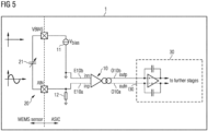
- FIG 5 shows an application of a sensor device 1 in which the transconductor circuitry 10 with adaptive biasing as shown in Figure 4B is used as an interface between a sensor 20 and an analog-to-digital converter 30.
- the sensor device 1 comprises the transconductor circuitry 10 with adaptive biasing which is configured to generate an output current signal outp, outn.
- the sensor 20 may be embodied as, for example, one of a MEMs microphone or a pressure sensor or a resistive sensor or an inductive sensor or a capacitive sensor or a seismic sensor.
- the sensor 20 includes a transducer 21 to detect an environmental signal impacting on the transducer 21.
- the transducer 21 is configured to generate voltage signals inn, inp in response to the environmental signal.
- the analog-to-digital converter 30 has an input side I30 to receive the output current signals outp, outn.
- the analog-to-digital converter 30 is configured to generate a digital output signal in response to the output current signal outn, outp.
- the analog-to-digital converter 30 may be configured as a converter with continuous timing.
- the transconductor circuitry 10 is connected to the sensor 20 to receive the voltage signals inp, inn from the sensor 20 at the input terminals E10a and E10b.
- the transconductor circuitry 10 is further connected to the analog-to-digital converter 30 to provide the output current signals outp, outn to the input side I30 of the analog-to-digital converter 30.
- the transconductor circuitry 10 and the analog-to-digital converter 30 may be embodied as an ASIC stage.
- the transconductor circuitry 10 is used as a sensor input stage which allows the biasing of the input transistors to be adjusted according to the level of the differential input signal.
- the transconductor circuitry is configured to use the sensing signal Vx, for example tapped between the degeneration resistors 170 and 180, and the reference signal Vrefx tapped at the source nodes of an auxiliary transistor pair to derive the required biasing current.
- the transconductor circuitry 10 may advantageously be implemented without using extra noise contributors apart from the inherently present components, for example input transistors and their bias current sources and degeneration resistors. Another advantage is that the power consumption is low when applying small differential input signals, increasing only with larger differential input signals. This is beneficial for audio applications, because the differential input signal is usually small most of the time.
- the transconductor circuitry 10 only shows low noise at small differential input signals, increasing only with larger differential input signals.
- the noise increase for large differential input signals is usually acceptable for audio applications, because the maximum SNR (signal-to-noise ratio) the human hearing can perceive is limited.
- the design of the circuitry allows the trade-off between THD (Total Harmonic Distortion) and power consumption to be adjusted efficiently during design. The provision of a high gain regulation loop which is costly to make stable at large signal dynamic range is not necessary.
Landscapes
- Engineering & Computer Science (AREA)
- Power Engineering (AREA)
- Amplifiers (AREA)
Claims (6)
- Transkonduktorschaltung mit adaptiver Arbeitspunkteinstellung, umfassend:- einen ersten Eingangsanschluss (E10a) zum Anlegen eines ersten Eingangssignals (inp),- einen zweiten Eingangsanschluss (E10b) zum Anlegen eines zweiten Eingangssignals (inn), wobei das erste und das zweite Eingangssignal (inp, inn) eine differentielle Eingangsspannung an die Transkonduktorschaltung (10) anlegen,- einen ersten Strompfad (101) mit einem ersten Transistor (150) und einer ersten steuerbaren Stromquelle (110) zum Einstellen eines ersten Arbeitspunktstroms des ersten Transistors (150) im ersten Strompfad (101), wobei der erste Transistor (150) einen Steuerknoten aufweist, der mit dem ersten Eingangsanschluss (E10a) gekoppelt ist,- einen zweiten Strompfad (102), der einen zweiten Transistor (160) und eine zweite steuerbare Stromquelle (120) enthält, um einen zweiten Arbeitspunktstrom des zweiten Transistors (160) in dem zweiten Strompfad (102) einzustellen, wobei der zweite Transistor (160) einen Steuerknoten aufweist, der mit dem zweiten Eingangsanschluss (E10b) gekoppelt ist,- eine Steuerschaltung (200), die dazu ausgebildet ist, die erste und die zweite steuerbare Stromquelle (110, 120) in Abhängigkeit von mindestens einem von einem ersten Potential eines ersten Knotens (N1) des ersten Strompfads (101) und einem zweiten Potential eines zweiten Knotens (N2) des zweiten Strompfads (102) zu steuern,- einen ersten Verbindungsstrompfad (103), der zwischen dem ersten Knoten (N1) des ersten Strompfads (101) und dem zweiten Knoten (N2) des zweiten Strompfads (102) angeordnet ist,- wobei der erste Knoten (N1) zwischen dem ersten Transistor (150) und der ersten steuerbaren Stromquelle (110) liegt, und der zweite Knoten (N2) zwischen dem zweiten Transistor (160) und der zweiten steuerbaren Stromquelle (120) liegt,- wobei die Steuerschaltung (200) einen Verstärker (250) mit einem Ausgangsknoten (0250) zur Erzeugung eines Steuersignals (CS) zur Steuerung der ersten und zweiten steuerbaren Stromquelle (110, 120) umfasst,- wobei der Verstärker (250) einen ersten Eingangsknoten (I250a) aufweist, wobei der erste Eingangsknoten (I250a) des Verstärkers (250) mit einem ersten internen Knoten (N103) des ersten Verbindungsstrompfades (103) verbunden ist,- wobei der erste Eingangsknoten (I250a) mit dem ersten und dem zweiten Strompfad (101, 102) derart gekoppelt ist, dass ein Abtastsignal (Vx) am ersten Eingangsknoten (I250a) des Verstärkers (250) in Abhängigkeit von einem von dem ersten Potenzial am ersten Knoten (N1) und dem zweiten Potenzial am zweiten Knoten (N2) geändert wird,- wobei der erste Verbindungsstrompfad (103) ein erstes Widerstandselement (170) und ein zweites Widerstandselement (180) umfasst,- wobei das erste Widerstandselement (170) zwischen dem ersten Knoten (N1) des ersten Strompfades (101) und dem ersten internen Knoten (N103) des ersten Verbindungsstrompfades (103) angeschlossen ist,- wobei das zweite Widerstandselement (180) zwischen dem zweiten Knoten (N2) des zweiten Strompfades (102) und dem ersten internen Knoten (N103) des ersten Verbindungsstrompfades (103) angeschlossen ist,- wobei der Verstärker (250) einen zweiten Eingangsknoten (I250b) zum Anlegen eines Referenzsignals (Vrefx) umfasst,- wobei der Verstärker (250) dazu ausgebildet ist, das Steuersignal (CS) in Abhängigkeit von dem Messsignal (Vx) und dem Referenzsignal (Vrefx) zu erzeugen,- wobei die Steuerschaltung (200) einen dritten Strompfad (201) und einen vierten Strompfad (202) umfasst,- wobei der dritte Strompfad (201) einen dritten Transistor (230) und eine erste Konstantstromquelle (210) enthält, um einen Arbeitspunktstrom des dritten Transistors (230) in dem dritten Strompfad (201) zu erzeugen, wobei der dritte Transistor (230) einen Steuerknoten aufweist, der mit dem ersten Eingangsanschluss (E10a) gekoppelt ist,- wobei der vierte Strompfad (202) einen vierten Transistor (240) und eine zweite Konstantstromquelle (220) enthält, um einen weiteren Arbeitspunktstrom des vierten Transistors (240) in dem vierten Strompfad (202) zu erzeugen, wobei der vierte Transistor (240) einen Steuerknoten aufweist, der mit dem zweiten Eingangsanschluss (E10b) gekoppelt ist,- wobei der zweite Eingangsknoten (I250b) des Verstärkers (250) mit dem dritten und dem vierten Strompfad (201, 202) derart gekoppelt ist, dass das Referenzsignal (Vrefx) in Abhängigkeit von einem dritten Potential an einem dritten Knoten (N3) des dritten Strompfades (201) und einem vierten Potential an einem vierten Knoten (N4) des vierten Strompfades (202) geändert wird,- wobei der dritte Knoten (N3) zwischen dem dritten Transistor (230) und der ersten Konstantstromquelle (210) liegt, und der vierte Knoten (N4) zwischen dem vierten Transistor (240) und der zweiten Konstantstromquelle (220) liegt,- wobei die Steuerschaltung (200) einen zweiten Verbindungsstrompfad (203) umfasst, der zwischen dem dritten Knoten (N3) des dritten Strompfades (201) und dem vierten Knoten (N4) des vierten Strompfades (202) angeordnet ist,- wobei der zweite Eingangsknoten (I250b) des Verstärkers (250) mit einem zweiten internen Knoten (N203) des zweiten Verbindungsstrompfades (203) verbunden ist,- wobei der zweite Verbindungsstrompfad (203) ein drittes Widerstandselement (260) und ein viertes Widerstandselement (270) umfasst,- wobei das dritte Widerstandselement (260) zwischen dem dritten Knoten (N3) des dritten Strompfades (201) und dem zweiten internen Knoten (N203) des zweiten Verbindungsstrompfades (203) angeschlossen ist,- wobei das vierte Widerstandselement (270) zwischen dem vierten Knoten (N4) des vierten Strompfades (202) und dem zweiten internen Knoten (N203) des zweiten Verbindungsstrompfades (203) angeschlossen ist,- wobei die Steuerschaltung (200) eine Stromsenke oder eine Stromquelle (283) umfasst, die mit dem ersten internen Knoten (N103) des ersten Verbindungsstrompfades (103) gekoppelt ist, oder- wobei die Steuerschaltung (200) eine Stromsenke oder eine Stromquelle (284) umfasst, die mit dem zweiten internen Knoten (N203) des zweiten Verbindungsstrompfades (203) gekoppelt ist.
- Transkonduktorschaltung nach Anspruch 1,- wobei der erste Strompfad (101) eine dritte steuerbare Stromquelle (130) enthält,- wobei der zweite Strompfad (102) eine vierte steuerbare Stromquelle (140) enthält,- wobei die Steuerschaltung (200) dazu ausgebildet ist, die dritte und die vierte steuerbare Stromquelle (130, 140) in Abhängigkeit von mindestens einem von dem ersten Potential am ersten Knoten (N1) des ersten Strompfades (101) und dem zweiten Potential am zweiten Knoten (N2) des zweiten Strompfades (102) zu steuern.
- Transkonduktorschaltung nach Anspruch 2, wobei die Steuerschaltung (200) dazu ausgebildet ist, das Steuersignal (CS) durch den Verstärker (250) zu erzeugen, um die erste und die zweite steuerbare Stromquelle (110, 120) und die dritte und die vierte steuerbare Stromquelle (130, 140) in Abhängigkeit von dem am ersten internen Knoten (N103) des ersten Verbindungsstrompfads (103) erfasste Messsignal (Vx) zu steuern.
- Transkonduktorschaltung nach einem der Ansprüche 1 bis 3, wobei eine jeweilige fünfte Konstantstromquelle (191, 192, 193, 194) parallel zu jeder der ersten steuerbaren Stromquelle (110), der zweiten steuerbaren Stromquelle (120), der dritten steuerbaren Stromquelle (130) und der vierten steuerbaren Stromquelle (140) geschaltet ist.
- Sensorvorrichtung, umfassend:- eine Transkonduktorschaltung (10) mit adaptiver Arbeitspunkteinstellung nach einem der Ansprüche 1 bis 4, wobei die Transkonduktorschaltung (10) dazu ausgebildet ist, ein Ausgangsstromsignal (outp, outn) zu erzeugen,- einen Sensor (20) mit einem Wandler (21) zum Erfassen eines auf den Wandler (21) einwirkenden Umgebungssignals, wobei der Wandler (21) dazu ausgebildet ist, ein Spannungssignal (inn, inp) in Abhängigkeit von dem Umgebungssignal zu erzeugen,- einen Analog-Digital-Wandler (30) mit einer Eingangsseite (130) zum Empfangen des Ausgangsstromsignals (outp, outn), wobei der Analog-Digital-Wandler (30) dazu ausgebildet ist, ein digitales Ausgangssignal in Abhängigkeit von dem Ausgangsstromsignal (outn, outp) zu erzeugen,- wobei die Transkonduktorschaltung (10) mit dem Sensor (20) verbunden ist, um das Spannungssignal (inn, inp) von dem Sensor (20) an dem ersten und zweiten Eingangsanschluss (E10a, E10b) der Transkonduktorschaltung zu empfangen, und ferner mit dem Analog-Digital-Wandler (30) verbunden ist, um das Ausgangsstromsignal (outp, outn) an der Eingangsseite (I30) des Analog-Digital-Wandlers (30) bereitzustellen.
- Die Sensorvorrichtung nach Anspruch 5, wobei der Sensor (20) als ein MEMS-Mikrofon, ein Drucksensor, ein Widerstandssensor, ein induktiver Sensor, ein kapazitiver Sensor oder als ein seismischer Sensor ausgebildet ist.
Priority Applications (5)
| Application Number | Priority Date | Filing Date | Title |
|---|---|---|---|
| EP18214610.0A EP3672073B1 (de) | 2018-12-20 | 2018-12-20 | Transkonduktorschaltung mit einstellbarer vorspannung |
| PCT/EP2019/083477 WO2020126475A1 (en) | 2018-12-20 | 2019-12-03 | Transconductor circuitry with adaptive biasing |
| US17/414,603 US12149219B2 (en) | 2018-12-20 | 2019-12-03 | Transconductor circuitry with adaptive biasing |
| CN201980084651.4A CN113728551B (zh) | 2018-12-20 | 2019-12-03 | 具有自适应偏置的跨导器电路 |
| JP2021530959A JP7241873B2 (ja) | 2018-12-20 | 2019-12-03 | 適応バイアスを有するトランスコンダクタ回路 |
Applications Claiming Priority (1)
| Application Number | Priority Date | Filing Date | Title |
|---|---|---|---|
| EP18214610.0A EP3672073B1 (de) | 2018-12-20 | 2018-12-20 | Transkonduktorschaltung mit einstellbarer vorspannung |
Publications (2)
| Publication Number | Publication Date |
|---|---|
| EP3672073A1 EP3672073A1 (de) | 2020-06-24 |
| EP3672073B1 true EP3672073B1 (de) | 2023-02-08 |
Family
ID=64901865
Family Applications (1)
| Application Number | Title | Priority Date | Filing Date |
|---|---|---|---|
| EP18214610.0A Active EP3672073B1 (de) | 2018-12-20 | 2018-12-20 | Transkonduktorschaltung mit einstellbarer vorspannung |
Country Status (5)
| Country | Link |
|---|---|
| US (1) | US12149219B2 (de) |
| EP (1) | EP3672073B1 (de) |
| JP (1) | JP7241873B2 (de) |
| CN (1) | CN113728551B (de) |
| WO (1) | WO2020126475A1 (de) |
Families Citing this family (3)
| Publication number | Priority date | Publication date | Assignee | Title |
|---|---|---|---|---|
| US12348196B2 (en) | 2021-09-21 | 2025-07-01 | Kabushiki Kaisha Toshiba | Semiconductor circuit |
| JP2023046207A (ja) * | 2021-09-21 | 2023-04-03 | 株式会社東芝 | 半導体回路 |
| US12352826B2 (en) | 2023-03-29 | 2025-07-08 | Arm Limited | Current measurement architecture |
Family Cites Families (13)
| Publication number | Priority date | Publication date | Assignee | Title |
|---|---|---|---|---|
| ATE136702T1 (de) * | 1991-09-25 | 1996-04-15 | Bell Telephone Mfg | Differenzverstärkeranordnung |
| US6023196A (en) * | 1998-08-03 | 2000-02-08 | Lucent Technologies Inc. | Bias circuit for transconductance amplifier |
| US6727757B1 (en) | 2003-01-02 | 2004-04-27 | Texas Instruments Incoporated | Biasing circuit for transconductors |
| US7057460B2 (en) | 2004-06-29 | 2006-06-06 | Rambus, Inc. | Differential amplifier with adaptive biasing and offset cancellation |
| JP4415821B2 (ja) | 2004-10-25 | 2010-02-17 | パナソニック電工株式会社 | 受信装置、トランスコンダクタンスアンプ |
| US7295068B2 (en) * | 2005-05-19 | 2007-11-13 | Beceem Communications Inc. | Increasing the linearity of a transconductance cell |
| US7321259B1 (en) * | 2005-10-06 | 2008-01-22 | Altera Corporation | Programmable logic enabled dynamic offset cancellation |
| JP4871590B2 (ja) | 2005-12-28 | 2012-02-08 | パナソニック株式会社 | トランスコンダクタを用いた積分器及びフィルタ回路 |
| JP2012029206A (ja) | 2010-07-27 | 2012-02-09 | Sharp Corp | トランスコンダクタ回路、ミキサ回路、無線機器 |
| US10211792B2 (en) * | 2012-04-04 | 2019-02-19 | Ams Ag | Sensor amplifier arrangement and method of amplifying a sensor signal |
| JP2015115654A (ja) | 2013-12-09 | 2015-06-22 | 株式会社東芝 | 単相差動変換回路およびアナログフロントエンド回路 |
| JP2018174477A (ja) | 2017-03-31 | 2018-11-08 | エイブリック株式会社 | トランスコンダクタンス増幅器 |
| US10804859B2 (en) * | 2018-12-10 | 2020-10-13 | Analog Devices, Inc. | Transimpedance amplifiers with feedforward current |
-
2018
- 2018-12-20 EP EP18214610.0A patent/EP3672073B1/de active Active
-
2019
- 2019-12-03 US US17/414,603 patent/US12149219B2/en active Active
- 2019-12-03 JP JP2021530959A patent/JP7241873B2/ja active Active
- 2019-12-03 WO PCT/EP2019/083477 patent/WO2020126475A1/en not_active Ceased
- 2019-12-03 CN CN201980084651.4A patent/CN113728551B/zh active Active
Also Published As
| Publication number | Publication date |
|---|---|
| US20220052660A1 (en) | 2022-02-17 |
| US12149219B2 (en) | 2024-11-19 |
| WO2020126475A1 (en) | 2020-06-25 |
| CN113728551B (zh) | 2024-11-01 |
| CN113728551A (zh) | 2021-11-30 |
| JP2022512084A (ja) | 2022-02-02 |
| JP7241873B2 (ja) | 2023-03-17 |
| EP3672073A1 (de) | 2020-06-24 |
Similar Documents
| Publication | Publication Date | Title |
|---|---|---|
| JP5092009B2 (ja) | 低ドロップアウト線形レギュレータ(ldo)、ldoを提供するための方法、およびldoを動作させるための方法 | |
| KR101588501B1 (ko) | 프로그램가능 이득 증폭기를 위한 시스템 및 방법 | |
| CN102882481B (zh) | 用于电容信号源放大器的系统和方法 | |
| CN107104648B (zh) | 一种放大电路 | |
| US6577184B2 (en) | Switched-capacitor, common-mode feedback circuit for a differential amplifier without tail current | |
| CN106712730B (zh) | 一种可调节信号且可编程的增益放大器 | |
| AU2007219317B2 (en) | Differential Amplifier with Current Source Controlled through Differential Feedback | |
| US12149219B2 (en) | Transconductor circuitry with adaptive biasing | |
| SE519691C2 (sv) | Operationsförstärkare med hög hastighet och hög förstärkning | |
| CN108540102B (zh) | 可编程增益放大装置 | |
| US12199575B2 (en) | Super source follower | |
| CN110710105A (zh) | 放大器装置和具有这种放大器装置的传感器装置 | |
| CN107171650B (zh) | 可变增益放大电路 | |
| KR100953243B1 (ko) | 차동 단상 변환 회로 | |
| JPH11161352A (ja) | 部分的に温度補正された低ノイズ電圧基準 | |
| US7643573B2 (en) | Power management in a data acquisition system | |
| JP5007937B2 (ja) | 減衰器 | |
| JP2014517582A (ja) | 増幅回路および受信チェーン | |
| JP2012169820A (ja) | プリアンプ回路、及びマイクロフォン | |
| Martins et al. | A programmable gain amplifier for load demodulation channel in an NFC reader chip | |
| JP7191598B2 (ja) | 増幅装置 | |
| JP7729065B2 (ja) | トランスインピーダンス増幅回路 | |
| Li et al. | A high gain and low noise instrument amplifier | |
| TW201919335A (zh) | 用於信號接收器中的雙模信號放大電路 | |
| CN109787567B (zh) | 用于信号接收器中的双模信号放大电路 |
Legal Events
| Date | Code | Title | Description |
|---|---|---|---|
| PUAI | Public reference made under article 153(3) epc to a published international application that has entered the european phase |
Free format text: ORIGINAL CODE: 0009012 |
|
| STAA | Information on the status of an ep patent application or granted ep patent |
Free format text: STATUS: THE APPLICATION HAS BEEN PUBLISHED |
|
| AK | Designated contracting states |
Kind code of ref document: A1 Designated state(s): AL AT BE BG CH CY CZ DE DK EE ES FI FR GB GR HR HU IE IS IT LI LT LU LV MC MK MT NL NO PL PT RO RS SE SI SK SM TR |
|
| AX | Request for extension of the european patent |
Extension state: BA ME |
|
| STAA | Information on the status of an ep patent application or granted ep patent |
Free format text: STATUS: REQUEST FOR EXAMINATION WAS MADE |
|
| 17P | Request for examination filed |
Effective date: 20201126 |
|
| RBV | Designated contracting states (corrected) |
Designated state(s): AL AT BE BG CH CY CZ DE DK EE ES FI FR GB GR HR HU IE IS IT LI LT LU LV MC MK MT NL NO PL PT RO RS SE SI SK SM TR |
|
| STAA | Information on the status of an ep patent application or granted ep patent |
Free format text: STATUS: EXAMINATION IS IN PROGRESS |
|
| 17Q | First examination report despatched |
Effective date: 20211126 |
|
| GRAP | Despatch of communication of intention to grant a patent |
Free format text: ORIGINAL CODE: EPIDOSNIGR1 |
|
| STAA | Information on the status of an ep patent application or granted ep patent |
Free format text: STATUS: GRANT OF PATENT IS INTENDED |
|
| INTG | Intention to grant announced |
Effective date: 20220722 |
|
| GRAS | Grant fee paid |
Free format text: ORIGINAL CODE: EPIDOSNIGR3 |
|
| GRAA | (expected) grant |
Free format text: ORIGINAL CODE: 0009210 |
|
| STAA | Information on the status of an ep patent application or granted ep patent |
Free format text: STATUS: THE PATENT HAS BEEN GRANTED |
|
| AK | Designated contracting states |
Kind code of ref document: B1 Designated state(s): AL AT BE BG CH CY CZ DE DK EE ES FI FR GB GR HR HU IE IS IT LI LT LU LV MC MK MT NL NO PL PT RO RS SE SI SK SM TR |
|
| REG | Reference to a national code |
Ref country code: GB Ref legal event code: FG4D |
|
| REG | Reference to a national code |
Ref country code: CH Ref legal event code: EP Ref country code: AT Ref legal event code: REF Ref document number: 1547684 Country of ref document: AT Kind code of ref document: T Effective date: 20230215 |
|
| REG | Reference to a national code |
Ref country code: IE Ref legal event code: FG4D |
|
| REG | Reference to a national code |
Ref country code: DE Ref legal event code: R096 Ref document number: 602018045998 Country of ref document: DE |
|
| REG | Reference to a national code |
Ref country code: LT Ref legal event code: MG9D |
|
| REG | Reference to a national code |
Ref country code: NL Ref legal event code: MP Effective date: 20230208 |
|
| REG | Reference to a national code |
Ref country code: AT Ref legal event code: MK05 Ref document number: 1547684 Country of ref document: AT Kind code of ref document: T Effective date: 20230208 |
|
| PG25 | Lapsed in a contracting state [announced via postgrant information from national office to epo] |
Ref country code: RS Free format text: LAPSE BECAUSE OF FAILURE TO SUBMIT A TRANSLATION OF THE DESCRIPTION OR TO PAY THE FEE WITHIN THE PRESCRIBED TIME-LIMIT Effective date: 20230208 Ref country code: PT Free format text: LAPSE BECAUSE OF FAILURE TO SUBMIT A TRANSLATION OF THE DESCRIPTION OR TO PAY THE FEE WITHIN THE PRESCRIBED TIME-LIMIT Effective date: 20230609 Ref country code: NO Free format text: LAPSE BECAUSE OF FAILURE TO SUBMIT A TRANSLATION OF THE DESCRIPTION OR TO PAY THE FEE WITHIN THE PRESCRIBED TIME-LIMIT Effective date: 20230508 Ref country code: NL Free format text: LAPSE BECAUSE OF FAILURE TO SUBMIT A TRANSLATION OF THE DESCRIPTION OR TO PAY THE FEE WITHIN THE PRESCRIBED TIME-LIMIT Effective date: 20230208 Ref country code: LV Free format text: LAPSE BECAUSE OF FAILURE TO SUBMIT A TRANSLATION OF THE DESCRIPTION OR TO PAY THE FEE WITHIN THE PRESCRIBED TIME-LIMIT Effective date: 20230208 Ref country code: LT Free format text: LAPSE BECAUSE OF FAILURE TO SUBMIT A TRANSLATION OF THE DESCRIPTION OR TO PAY THE FEE WITHIN THE PRESCRIBED TIME-LIMIT Effective date: 20230208 Ref country code: HR Free format text: LAPSE BECAUSE OF FAILURE TO SUBMIT A TRANSLATION OF THE DESCRIPTION OR TO PAY THE FEE WITHIN THE PRESCRIBED TIME-LIMIT Effective date: 20230208 Ref country code: ES Free format text: LAPSE BECAUSE OF FAILURE TO SUBMIT A TRANSLATION OF THE DESCRIPTION OR TO PAY THE FEE WITHIN THE PRESCRIBED TIME-LIMIT Effective date: 20230208 Ref country code: AT Free format text: LAPSE BECAUSE OF FAILURE TO SUBMIT A TRANSLATION OF THE DESCRIPTION OR TO PAY THE FEE WITHIN THE PRESCRIBED TIME-LIMIT Effective date: 20230208 |
|
| PG25 | Lapsed in a contracting state [announced via postgrant information from national office to epo] |
Ref country code: SE Free format text: LAPSE BECAUSE OF FAILURE TO SUBMIT A TRANSLATION OF THE DESCRIPTION OR TO PAY THE FEE WITHIN THE PRESCRIBED TIME-LIMIT Effective date: 20230208 Ref country code: PL Free format text: LAPSE BECAUSE OF FAILURE TO SUBMIT A TRANSLATION OF THE DESCRIPTION OR TO PAY THE FEE WITHIN THE PRESCRIBED TIME-LIMIT Effective date: 20230208 Ref country code: IS Free format text: LAPSE BECAUSE OF FAILURE TO SUBMIT A TRANSLATION OF THE DESCRIPTION OR TO PAY THE FEE WITHIN THE PRESCRIBED TIME-LIMIT Effective date: 20230608 Ref country code: GR Free format text: LAPSE BECAUSE OF FAILURE TO SUBMIT A TRANSLATION OF THE DESCRIPTION OR TO PAY THE FEE WITHIN THE PRESCRIBED TIME-LIMIT Effective date: 20230509 Ref country code: FI Free format text: LAPSE BECAUSE OF FAILURE TO SUBMIT A TRANSLATION OF THE DESCRIPTION OR TO PAY THE FEE WITHIN THE PRESCRIBED TIME-LIMIT Effective date: 20230208 |
|
| P01 | Opt-out of the competence of the unified patent court (upc) registered |
Effective date: 20230822 |
|
| PG25 | Lapsed in a contracting state [announced via postgrant information from national office to epo] |
Ref country code: SM Free format text: LAPSE BECAUSE OF FAILURE TO SUBMIT A TRANSLATION OF THE DESCRIPTION OR TO PAY THE FEE WITHIN THE PRESCRIBED TIME-LIMIT Effective date: 20230208 Ref country code: RO Free format text: LAPSE BECAUSE OF FAILURE TO SUBMIT A TRANSLATION OF THE DESCRIPTION OR TO PAY THE FEE WITHIN THE PRESCRIBED TIME-LIMIT Effective date: 20230208 Ref country code: EE Free format text: LAPSE BECAUSE OF FAILURE TO SUBMIT A TRANSLATION OF THE DESCRIPTION OR TO PAY THE FEE WITHIN THE PRESCRIBED TIME-LIMIT Effective date: 20230208 Ref country code: DK Free format text: LAPSE BECAUSE OF FAILURE TO SUBMIT A TRANSLATION OF THE DESCRIPTION OR TO PAY THE FEE WITHIN THE PRESCRIBED TIME-LIMIT Effective date: 20230208 Ref country code: CZ Free format text: LAPSE BECAUSE OF FAILURE TO SUBMIT A TRANSLATION OF THE DESCRIPTION OR TO PAY THE FEE WITHIN THE PRESCRIBED TIME-LIMIT Effective date: 20230208 |
|
| REG | Reference to a national code |
Ref country code: DE Ref legal event code: R097 Ref document number: 602018045998 Country of ref document: DE |
|
| PG25 | Lapsed in a contracting state [announced via postgrant information from national office to epo] |
Ref country code: SK Free format text: LAPSE BECAUSE OF FAILURE TO SUBMIT A TRANSLATION OF THE DESCRIPTION OR TO PAY THE FEE WITHIN THE PRESCRIBED TIME-LIMIT Effective date: 20230208 |
|
| PLBE | No opposition filed within time limit |
Free format text: ORIGINAL CODE: 0009261 |
|
| STAA | Information on the status of an ep patent application or granted ep patent |
Free format text: STATUS: NO OPPOSITION FILED WITHIN TIME LIMIT |
|
| 26N | No opposition filed |
Effective date: 20231109 |
|
| PG25 | Lapsed in a contracting state [announced via postgrant information from national office to epo] |
Ref country code: SI Free format text: LAPSE BECAUSE OF FAILURE TO SUBMIT A TRANSLATION OF THE DESCRIPTION OR TO PAY THE FEE WITHIN THE PRESCRIBED TIME-LIMIT Effective date: 20230208 |
|
| PG25 | Lapsed in a contracting state [announced via postgrant information from national office to epo] |
Ref country code: IT Free format text: LAPSE BECAUSE OF FAILURE TO SUBMIT A TRANSLATION OF THE DESCRIPTION OR TO PAY THE FEE WITHIN THE PRESCRIBED TIME-LIMIT Effective date: 20230208 |
|
| REG | Reference to a national code |
Ref country code: CH Ref legal event code: PL |
|
| PG25 | Lapsed in a contracting state [announced via postgrant information from national office to epo] |
Ref country code: LU Free format text: LAPSE BECAUSE OF NON-PAYMENT OF DUE FEES Effective date: 20231220 |
|
| PG25 | Lapsed in a contracting state [announced via postgrant information from national office to epo] |
Ref country code: MC Free format text: LAPSE BECAUSE OF FAILURE TO SUBMIT A TRANSLATION OF THE DESCRIPTION OR TO PAY THE FEE WITHIN THE PRESCRIBED TIME-LIMIT Effective date: 20230208 |
|
| GBPC | Gb: european patent ceased through non-payment of renewal fee |
Effective date: 20231220 |
|
| REG | Reference to a national code |
Ref country code: BE Ref legal event code: MM Effective date: 20231231 |
|
| PG25 | Lapsed in a contracting state [announced via postgrant information from national office to epo] |
Ref country code: MC Free format text: LAPSE BECAUSE OF FAILURE TO SUBMIT A TRANSLATION OF THE DESCRIPTION OR TO PAY THE FEE WITHIN THE PRESCRIBED TIME-LIMIT Effective date: 20230208 Ref country code: LU Free format text: LAPSE BECAUSE OF NON-PAYMENT OF DUE FEES Effective date: 20231220 |
|
| REG | Reference to a national code |
Ref country code: IE Ref legal event code: MM4A |
|
| PG25 | Lapsed in a contracting state [announced via postgrant information from national office to epo] |
Ref country code: IE Free format text: LAPSE BECAUSE OF NON-PAYMENT OF DUE FEES Effective date: 20231220 |
|
| PG25 | Lapsed in a contracting state [announced via postgrant information from national office to epo] |
Ref country code: GB Free format text: LAPSE BECAUSE OF NON-PAYMENT OF DUE FEES Effective date: 20231220 |
|
| PG25 | Lapsed in a contracting state [announced via postgrant information from national office to epo] |
Ref country code: BE Free format text: LAPSE BECAUSE OF NON-PAYMENT OF DUE FEES Effective date: 20231231 |
|
| PG25 | Lapsed in a contracting state [announced via postgrant information from national office to epo] |
Ref country code: FR Free format text: LAPSE BECAUSE OF NON-PAYMENT OF DUE FEES Effective date: 20231231 |
|
| PG25 | Lapsed in a contracting state [announced via postgrant information from national office to epo] |
Ref country code: CH Free format text: LAPSE BECAUSE OF NON-PAYMENT OF DUE FEES Effective date: 20231231 |
|
| PG25 | Lapsed in a contracting state [announced via postgrant information from national office to epo] |
Ref country code: IE Free format text: LAPSE BECAUSE OF NON-PAYMENT OF DUE FEES Effective date: 20231220 Ref country code: GB Free format text: LAPSE BECAUSE OF NON-PAYMENT OF DUE FEES Effective date: 20231220 Ref country code: FR Free format text: LAPSE BECAUSE OF NON-PAYMENT OF DUE FEES Effective date: 20231231 Ref country code: CH Free format text: LAPSE BECAUSE OF NON-PAYMENT OF DUE FEES Effective date: 20231231 Ref country code: BE Free format text: LAPSE BECAUSE OF NON-PAYMENT OF DUE FEES Effective date: 20231231 |
|
| PG25 | Lapsed in a contracting state [announced via postgrant information from national office to epo] |
Ref country code: BG Free format text: LAPSE BECAUSE OF FAILURE TO SUBMIT A TRANSLATION OF THE DESCRIPTION OR TO PAY THE FEE WITHIN THE PRESCRIBED TIME-LIMIT Effective date: 20230208 |
|
| PG25 | Lapsed in a contracting state [announced via postgrant information from national office to epo] |
Ref country code: BG Free format text: LAPSE BECAUSE OF FAILURE TO SUBMIT A TRANSLATION OF THE DESCRIPTION OR TO PAY THE FEE WITHIN THE PRESCRIBED TIME-LIMIT Effective date: 20230208 |
|
| PG25 | Lapsed in a contracting state [announced via postgrant information from national office to epo] |
Ref country code: CY Free format text: LAPSE BECAUSE OF FAILURE TO SUBMIT A TRANSLATION OF THE DESCRIPTION OR TO PAY THE FEE WITHIN THE PRESCRIBED TIME-LIMIT; INVALID AB INITIO Effective date: 20181220 |
|
| PG25 | Lapsed in a contracting state [announced via postgrant information from national office to epo] |
Ref country code: HU Free format text: LAPSE BECAUSE OF FAILURE TO SUBMIT A TRANSLATION OF THE DESCRIPTION OR TO PAY THE FEE WITHIN THE PRESCRIBED TIME-LIMIT; INVALID AB INITIO Effective date: 20181220 |
|
| PG25 | Lapsed in a contracting state [announced via postgrant information from national office to epo] |
Ref country code: TR Free format text: LAPSE BECAUSE OF FAILURE TO SUBMIT A TRANSLATION OF THE DESCRIPTION OR TO PAY THE FEE WITHIN THE PRESCRIBED TIME-LIMIT Effective date: 20230208 |
|
| PGFP | Annual fee paid to national office [announced via postgrant information from national office to epo] |
Ref country code: DE Payment date: 20251211 Year of fee payment: 8 |