EP3668088B1 - Nutzfahrzeug - Google Patents
Nutzfahrzeug Download PDFInfo
- Publication number
- EP3668088B1 EP3668088B1 EP18868136.5A EP18868136A EP3668088B1 EP 3668088 B1 EP3668088 B1 EP 3668088B1 EP 18868136 A EP18868136 A EP 18868136A EP 3668088 B1 EP3668088 B1 EP 3668088B1
- Authority
- EP
- European Patent Office
- Prior art keywords
- video
- controller
- video data
- camera
- work
- Prior art date
- Legal status (The legal status is an assumption and is not a legal conclusion. Google has not performed a legal analysis and makes no representation as to the accuracy of the status listed.)
- Active
Links
Images


Classifications
-
- B—PERFORMING OPERATIONS; TRANSPORTING
- B62—LAND VEHICLES FOR TRAVELLING OTHERWISE THAN ON RAILS
- B62D—MOTOR VEHICLES; TRAILERS
- B62D49/00—Tractors
- B62D49/06—Tractors adapted for multi-purpose use
- B62D49/0614—Tractors adapted for multi-purpose use equipped with visual aids for positioning implements or to control working condition
-
- H—ELECTRICITY
- H04—ELECTRIC COMMUNICATION TECHNIQUE
- H04N—PICTORIAL COMMUNICATION, e.g. TELEVISION
- H04N7/00—Television systems
- H04N7/18—Closed-circuit television [CCTV] systems, i.e. systems in which the video signal is not broadcast
-
- B—PERFORMING OPERATIONS; TRANSPORTING
- B66—HOISTING; LIFTING; HAULING
- B66C—CRANES; LOAD-ENGAGING ELEMENTS OR DEVICES FOR CRANES, CAPSTANS, WINCHES, OR TACKLES
- B66C13/00—Other constructional features or details
Definitions
- the present invention relates to a self-propelled work vehicle.
- a work vehicle which is generally called a rough terrain crane or the like
- an operation unit for causing a travel body to travel and an operation unit that runs a rotating body and a boom are disposed in the same cabin.
- the work vehicle has a large size, and thus an operator is likely to have a blind spot.
- Patent Literature 2 discloses a crane truck in which image data obtained from imaging performed by a camera installed on a travel body is wirelessly transmitted to a rotating body.
- Wireless communication has a problem of a delay greater than wired communication has. Therefore, when items of video data acquired by the plurality of cameras mounted in the travel body are individually transmitted, for example, some items of video data will be subjected to a transmission delay, and thus there is a possibility that it is not possible to display a plurality of videos imaged at the same time point on a display.
- a first object thereof is to provide a technology for appropriately transmitting video data between a travel body and a work body in a work vehicle that displays, in a cabin provided in the work body, videos imaged by a plurality of cameras mounted in the travel body
- a second object thereof is to provide a technology for displaying, in a cabin, videos imaged at the same time point by cameras in a work vehicle that wirelessly transmits the video data to the work body.
- the present invention since composite video data obtained by composition of the videos imaged by the plurality of cameras is transmitted between the travel body and the work body, the number of communication cables which are added to a slip ring can be reduced, or the plurality of items of video data can be reliably synchronized. As a result, signals of videos imaged by the plurality of cameras are inhibited from interfering with each other, and thus an image quality improves.
- first video data and second video data are synchronized and then wirelessly transmitted from the first controller to the second controller, the videos imaged by the cameras at the same time point can be displayed in the cabin.
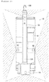
- a rough terrain crane 10 mainly includes a lower travel body 20 and an upper slewing body 30.
- the rough terrain crane 10 travels to a destination by the lower travel body 20 and runs the upper slewing body 30 in a predetermined manner to the destination.
- the rough terrain crane 10 is an example of a work vehicle.
- the lower travel body 20 includes a pair of right and left front wheels 21 and a pair of right and left rear wheels 22.
- the front wheels 21 are steering wheels and are steered by steering 42B to be described below.
- the rear wheels 22 are driving wheels and are rotated by a drive force of an engine (not illustrated), the drive force being transmitted via a transmission (not illustrated).
- the lower travel body 20 includes outriggers 23 and 24.
- the outrigger 23 is disposed at a front end of the lower travel body 20, and the outrigger 24 is disposed at a rear end of the lower travel body 20.
- the outriggers 23 and 24 can have a change between an outrigging state of being in contact with the ground at a position at which the outriggers project out from the lower travel body 20 and a retracting state of retracting into the lower travel body 20 in a state where the outriggers are separated from the ground.
- the outriggers 23 and 24 come into the outrigging state when the upper slewing body 30 is run, and thereby a posture of the rough terrain crane 10 is stabilized.
- the outriggers 23 and 24 come into the retracting state when the lower travel body 20 travels.
- the upper slewing body 30 is rotatably supported by the lower travel body 20 via a rotating bearing (not illustrated).
- the upper rotating body 30 rotates by a drive force of a rotating motor 71 (refer to Figure 4 ) which is transmitted thereto.
- a rotating angle of the upper slewing body 30 indicates an angle in a clockwise direction when an angle in a forward direction of the lower travel body 20 is set to 0°.
- the upper slewing body 30 mainly includes a telescopic boom 32, a hook 33, and a cabin 40.
- the upper slewing body 30, the telescopic boom 32, and the hook 33 are examples of a work body.
- a derricking cylinder 72 causes the telescopic boom 32 to perform derricking movement
- a telescopic cylinder 73 causes the telescopic boom to be telescopic.
- a proximal end 32A of the telescopic boom 32 is supported by the upper slewing body 30, between the front end and the rear end of the lower travel body 20.
- a distal end 32B of the telescopic boom 32 is positioned at a front side from the front end of the lower travel body 20.
- a traveling posture of the rough terrain crane 10 a state where the rotating angle of the upper slewing body 30 is 0°, the telescopic boom 32 is most lowered, and the telescopic boom 32 has the shortest length is referred to as a traveling posture of the rough terrain crane 10.
- the telescopic boom 32 is extended more toward the front side from the front end of the lower travel body 20.
- a jib (not illustrated) for extending a work radius and a work height may be detachably attached to the distal end 32B of the telescopic boom 32.
- the hook 33 is suspended by a wire 38 from the distal end 32B of the telescopic boom 32 or a distal end of the jib and thus is lifted and lowered by a winch 74 (refer to Figure 4 ) which winds or unwinds the wire 38.
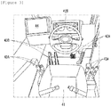
- the cabin 40 has a box shape with an interior space. An operator who operates the rough terrain crane 10 occupies the interior space.
- the cabin 40 is supported by the upper slewing body 30, at the rear side from the front end of the lower travel body 20 and the front side from the proximal end 32A of the telescopic boom 32.
- the cabin 40 is disposed adjacent to the telescopic boom 32 on the right.
- a positional relationship between the telescopic boom 32 and the cabin 40 is not limited to an example described above, and the cabin 40 may be disposed adjacent to the telescopic boom 32 on the left.
- a seat 41, a first operation unit 42, a second operation unit 43, and a display 44 are accommodated in the interior space of the cabin 40.
- the first operation unit 42 receives an instruction of the operator for causing the lower travel body 20 to travel. More specifically, the first operation unit 42 mainly includes a plurality of pedals 42A and the steering 42B.
- the pedals 42A receive an instruction for accelerating or decelerating the lower travel body 20, and examples of the pedal include an accelerator pedal, a brake pedal, or a clutch pedal.
- the steering 42B receives an operation indicating an instruction of a traveling direction of the lower travel body 20.
- the first operation unit 42 employs a well-known configuration, and thus the detailed description thereof is omitted.
- the second operation unit 43 changes the state of the outriggers 23 and 24, rotates the upper slewing body 30, causes the telescopic boom 32 to be extended or retracted and to perform derricking movement, and receives an instruction for lifting or lowering the hook 33.
- the second operation unit 43 is configured of a lever 43A, a pedal 43B, a switch (not illustrated), or the like.
- the second operation unit 43 employs a well-known configuration, and thus the detailed description thereof is omitted.
- the display 44 is disposed at a left-hand position from a center in a right-left direction in the cabin 40. More specifically, the display 44 is disposed adjacent to the steering 42B on the left.
- the display 44 displays a state of the rough terrain crane 10. More specifically, the display 44 displays a speed of the lower travel body 20, states of the outriggers 23 and 24, a rotating angle of the upper slewing body 30, an extension length and a derrick angle of the telescopic boom 32, or the like.
- the display 44 displays a video imaged by cameras 61 to 64 to be described below.
- the operator sitting on the seat 41 can operate the first operation unit 42 and the second operation unit 43 and can visually recognize information displayed on the display 44. More specifically, the operator can cause the lower travel body 20 to travel and can run the upper slewing body 30 and the telescopic boom 32, in a state of sitting on the seat 41. In the traveling posture of the rough terrain crane 10, an upper end of the telescopic boom 32 is positioned higher than a sight line of the operator sitting on the seat 41. In other words, the operator sitting on the seat 41 of the rough terrain crane 10 in the traveling posture has to cause the rough terrain crane 10, in a state where it is difficult to see right front of the lower travel body 20 and a left side of the lower travel body 20, to run.
- the cameras 61 to 64 image an object and generate video data.
- the cameras 61 to 64 generate the video data indicating videos (moving images).
- the cameras 61 to 64 are desirably wide-angle (for example, 80° to 240°) cameras used to generate bird's-eye images.
- the cameras 61 to 64 are attached to respective portions of the rough terrain crane 10 and have different orientations from each other.
- the cameras 61 to 64 are drawn in a large size in Figures 1 and 2 ; however, it is desirable to use small-sized cameras.
- the camera 61 is attached to the front end of the lower travel body 20 at the center in the right-left direction.
- the camera 61 is attached below the telescopic boom 32 which is most lowered.
- the camera 61 according to the embodiment is attached to a front bumper; however, a specific attachment position of the camera 61 is not limited thereto.
- the camera 61 is oriented toward a front side of the rough terrain crane 10. In other words, the camera 61 images the front side of the rough terrain crane 10 at a viewing angle of 80° to 240°.
- the camera 61 is an example of a first camera, and a video imaged by the camera 61 is an example of a first video.
- the camera 62 is attached to a right-hand end of the upper slewing body 30.
- the camera 62 according to the embodiment is attached to a rear side of the cabin 40; however, a specific attachment position of the camera 62 is not limited thereto.
- the camera 62 is oriented toward a right-hand side of the rough terrain crane 10 in the traveling posture. In other words, the camera 62 images the right-hand side of the rough terrain crane 10 at a viewing angle of 80° to 240°.
- the camera 62 is an example of a third camera, and a video imaged by the camera 62 is an example of a third video.
- the camera 63 is attached to a left-hand end of the upper slewing body 30.
- the camera 63 according to the embodiment is attached to the same position as that of the camera 62 in a front-rear direction; however, a specific attachment position of the camera 63 is not limited thereto.
- the camera 63 is oriented toward a left-hand side of the rough terrain crane 10 in the traveling posture. In other words, the camera 63 images the left-hand side of the rough terrain crane 10 at a viewing angle of 80° to 240°.
- the camera 63 is an example of a fourth camera, and a video imaged by the camera 63 is an example of a fourth video.
- the camera 64 is attached to the rear end of the lower travel body 20 at the center in the right-left direction.
- the camera 64 may be attached to a weight support that supports a counterweight (not illustrated).
- the camera 64 is oriented toward a rear side of the rough terrain crane 10. In other words, the camera 64 images the rear side of the rough terrain crane 10 at a viewing angle of 80° to 240°.
- the camera 64 is an example of a second camera, and a video imaged by the camera 64 is an example of a second video.
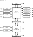
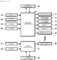
- the rough terrain crane 10 includes a first controller 51, a first storage unit 52, a second controller 53, and a second storage unit 54.
- the first controller 51 and the first storage unit 52 are provided in the lower travel body 20.
- the second controller 53 and the second storage unit 54 are provided in the upper slewing body 30.
- the first controller 51 and the second controller 53 are connected to each other via a plurality of communication cables (not illustrated) passing through a slip ring 50.
- the first controller 51 and the second controller 53 control the running of the rough terrain crane 10.
- the first controller 51 and the second controller 53 may be realized by a central processing unit (CPU) that executes a program stored in the first storage unit 52 and the second storage unit 54, may be realized by a hardware circuit, or may be realized by a combination thereof.
- the first storage unit 52 and the second storage unit 54 store the program which is executed by the CPU and various items of information which are temporarily stored during execution of the program.
- the first controller 51 controls operations of the cameras 61 and 64.
- the first controller 51 causes the cameras 61 and 64 to start imaging and acquires first video data (hereinafter, referred to as "video data F") and second video data (hereinafter, referred to as "video data B") generated by the cameras 61 and 64.
- the first controller 51 performs composition of the video data B and F acquired by the cameras 61 and 64 to generate first composite video data and transmits the generated first composite video data to the second controller 53 via the communication cable passing through the slip ring 50.
- a process for generating the first composite video data is described in detail below.
- the second controller 53 receives the first composite data from the first controller 51 via the communication cable passing through the slip ring 50.
- the second controller 53 controls operations of the cameras 62 and 63.
- the second controller 53 causes the cameras 62 and 63 to start imaging and acquires third video data (hereinafter, referred to as "video data R") and fourth video data (hereinafter, referred to as "video data L”) generated by the cameras 62 and 63.
- the second controller 53 performs composition of the first composite data, the video data R, and the video data L to generate second composite video data and displays a second composite video indicated by the second composite video data, on a display 44.
- a process for generating the second composite video data is described in detail below.
- the second controller 53 acquires operation signals which are output from the first operation unit 42 and the second operation unit 43.
- the second controller 53 controls a direction and a flow rate of operating oil to be supplied in response to the operation signal which is output from the second operation unit 43, thereby actuating an actuator such as the rotating motor 71, the derricking cylinder 72, the telescopic cylinder 73, or the winch 74.
- the actuator of the present invention is not limited to a hydraulic actuator and may be an electric actuator.
- the second controller 53 changes a steering angle of the front wheels 21, controls a rotational speed of an engine, and actuates a brake (not illustrated), in response to the operation signal which is output from the first operation unit 42.
- the second controller 53 acquires detection signals which are output from a rotating-angle sensor (not illustrated) that detects a rotating angle of the upper slewing body 30, a derrick-angle sensor (not illustrated) that detects a derrick angle of the telescopic boom 32, a length sensor that detects a telescopic length of the telescopic boom 32, and a wire sensor that detects an unwinding length of the wire 38 by the winch 74.
- the second controller 53 determines the rotating angle of the upper slewing body 30, the derrick angle of the telescopic boom 32, the telescopic length of the telescopic boom 32, and the unwinding length of the wire 38, based on the detection signals acquired by the various sensors.
- Figure 5 is a plan view illustrating a state where the rough terrain crane 10 approaches an intersection point.
- the rough terrain crane 10 in Figure 5 there are a human 81 who is crossing a crosswalk at a front left side and a bicycle 82 running alongside at a left-hand side.
- the operator occupying the cabin 40 of the rough terrain crane 10 in Figure 5 is not possible to visually recognize the human 81 and the bicycle 82 due to interference of the telescopic boom 32.
- Figure 6 is a video displayed on the display 44 of the rough terrain crane 10 in Figure 5 .
- the video illustrated in Figure 5 is obtained by composition of videos imaged by the cameras 61 to 64. More specifically, the video illustrated in Figure 5 is a bird's-eye video obtained by composition of videos showing a situation in a bird's-eye view from above around the rough terrain crane 10.
- operations of the first controller 51 and the second controller 53 for displaying the video illustrated in Figure 5 on the display 44 will be described with reference to Figure 7 .
- the first controller 51 and the second controller 53 cause the cameras 61 to 64 to start imaging simultaneously.
- the second controller 53 instructs a start of imaging to the cameras 61 and 64 through the first controller 51 and instructs an imaging start to the cameras 62 and 63 according to reception of an instruction for displaying the video on the display 44 through the second operation unit 43.
- a trigger of the imaging start of the cameras 61 to 64 is not limited to an example described above.
- the imaging start may be performed at a timing at which the engine starts or may be at a timing when the outriggers 23 and 24 has a change in states of the retracting state and the outrigging state from one to the other state.
- the videos imaged by the cameras 61 to 64 are configured of a plurality of images (that is, still images) arranged in an imaging order.
- the cameras 61 to 64 output, to the first controller 51 and the second controller 53, video data containing a plurality of images captured at predetermined time intervals (for example, an interval of 1/60 seconds).
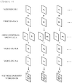
- the first controller 51 acquires, from the camera 61, the video data F containing a plurality of images F 1 , F 2 , F 3 , ⁇ arranged in an imaging order and acquires, from the camera 64, the video data B containing a plurality of images B 1 , B 2 , B 3 , ⁇ arranged in an imaging order.
- the second controller 53 acquires, from the camera 62, the video data R containing a plurality of images R 1 , R 2 , R 3 , ⁇ arranged in an imaging order and acquires, from the camera 63, the video data L containing a plurality of images L 1 , L 2 , L 3 , ⁇ arranged in an imaging order.
- the first controller 51 performs composition of a video indicated by the video data F and a video indicated by the video data B so as to generate the first composite video data indicating a first composite video. More specifically, the first controller 51 performs composition of images corresponding to the video data F and B to generate a composite image and arranges a plurality of generated composite images in an imaging order to generate the first composite video data. For example, the corresponding image indicates images obtained at the same turn in the imaging order, images captured at the same time point, or the like of the plurality of images contained in the respective video data F and B.
- a process for generating the first composite video data is an example of a first composition process.
- the composite image which is generated in the first composition process is a bird's-eye image of the front side and the rear side of the rough terrain crane 10 in a bird's-eye view from above.
- An algorithm for generating the bird's-eye image is already known, and thus the detailed description thereof is omitted; however, the following method is considered.
- the first controller 51 executes a correction process for correcting a distortion due to a lens by multiplying a coefficient based on a lens distortion coefficient, an aspect ratio, or the like to coordinate values of pixels of images F 1 and B 1 .
- the first controller 51 executes a bird's-eye view process for converting into images (individual bird's-eye images) in a view looking down from a virtual observing point set above the rough terrain crane 10 by multiplying various coefficients based on a camera attaching angle or the like to coordinate values of the pixels of the images F1 and B 1 .
- the first controller 51 displays a crane image imitating a shape of the rough terrain crane 10 at the center, displays the image F 1 converted in the bird's-eye view process above the crane image, displays the image B 1 converted in the bird's-eye view process below the crane image, and generates a composite image C 1 obtained by composition of the images F 1 and B 1 .
- the same is true of methods for generating composite images C 2 and C 3 .
- the first controller 51 transmits the first composite video data generated in the first composition process to the second controller 53 via the communication cable passing through the slip ring 50.
- This process is an example of a transmission process.
- the second controller 53 receives the first composite video data from the first controller 51 via the communication cable.
- This process is an example of a reception process.
- the second controller 53 performs composition of a video indicated by the first composite video data, a video indicated by the video data R, and a video indicated by the video data L so as to generate the second composite video data indicating a second composite video.
- This process is an example of a second composition process.
- the detailed description of the same point between the first composition process and the second composition process is omitted, and differences are mainly described.
- the second controller 53 performs composition of images corresponding to the first composite video data and the video data R and L to generate a composite image and arranges a plurality of generated composite images in an imaging order to generate the second composite video data.
- the second controller 53 executes the correction process and the bird's-eye view process on images R 1 and L 1 .
- the second controller 53 displays the image R 1 converted in the bird's-eye view process at a right-hand side from the crane image of the composite image C 1 and displays the image L 1 converted in the bird's-eye view process at a left-hand side from the crane image of the composite image C 1 so as to generate a composite image C 1 ' obtained by composition of the composite image C 1 and the images R 1 and L 1 .
- the same is true of methods for generating composite images C 2 ' and C 3 '.
- the second controller 53 displays, on the display 44, the second composite video containing the composite images C 1 ', C 2 ', C 3 ', ⁇ generated in the second composition process.
- This process is an example of a display process.
- the first composition process, the transmission process, the reception process, the second composition process, and the display process are executed in parallel with each other.
- the images captured by the cameras 61 to 64 are subjected to the composition in real time and are displayed on the display 44. Consequently, the operator can know the situation around the rough terrain crane 10 in real time, in the cabin 40.
- the first composite video data obtained by composition of the videos imaged by the plurality of cameras 61 and 64 is wirelessly transmitted between the lower travel body 20 and the upper slewing body 30, the number of communication cables which are added to the slip ring 50 can be reduced, compared to a case where the plurality of items of video data F and B are individually transmitted via cables. Furthermore, the first composite video data is transmitted without a communication cable or the like and thus is not influenced by noise, and disturbance of a camera video is avoided. As a result, it is advantageous in that an image quality improves.
- the videos imaged by the cameras 61 to 64 are converted into the bird's-eye images to be displayed on the display 44. Consequently, the operator who occupies the cabin 40 can appropriately know the situation around the rough terrain crane 10, can cause the lower travel body 20 to travel, can change the states of the outriggers 23 and 24, can rotate the upper slewing body 30, can cause the telescopic boom 32 to performing the derrick and telescopic movement, and can lift and lower the hook 33.
- the first controller 51 may generate composite videos F 1 , B 1 , F 2 , B 2 , F 3 , B 3 , ⁇ obtained by alternately arranging the images F 1 , F 2 , F 3 , ⁇ contained in the video data F and the images B 1 , B 2 , B 3 , ⁇ contained in the video data B.
- the first controller 51 may perform the composition of the plurality of videos spatially or may perform the composition of the plurality of videos temporarily in the first composition process.
- the second controller 53 may perform composition of the images F 1 and B 1 contained in the first composite video data, the image R 1 contained in the video data R, and the image L 1 contained in the video data L so as to generate the composite image C 1 '.
- a communication route of the video data between the first controller 51 and the second controller 53 is not limited to the cable.
- the first controller 51 may include a first wireless communication unit 55
- the second controller 53 may include a second wireless communication unit 56.
- the first wireless communication unit 55 and the second wireless communication unit 56 are hardware including a conversion circuit that converts one of a wireless signal and the video data into the other in accordance with a predetermined wireless communication protocol and an antenna that transmits and receives a wireless signal converted in the conversion circuit.
- the wireless communication protocol Wi-Fi (registered trademark), Bluetooth (registered trademark), wireless HDMI (registered trademark), or the like can be employed.
- the first controller 51 may wirelessly transmit the first composite video data to the second controller 53 via the first wireless communication unit 55 in the transmission process.
- the second controller 53 may wirelessly receive the first composite video data from the first controller 51 via the second wireless communication unit 56 in the reception process.
- Modification Example 2 without adding a communication cable for the video data to the slip ring 50, the video data obtained by the cameras 61 and 64 attached to the lower travel body 20 can be transmitted to the upper slewing body 30.
- the first controller 51 may add a timestamp indicating an imaging time point to each of the images F 1 , F 2 , F 3 , ⁇ contained in the video data F and may wirelessly transmit the video data F, to which the timestamp has been added, to the second controller 53 via the first wireless communication unit 55. Consequently, the timestamp is added to the image, and thus it is possible to determine whether a video is a real-time video.
- the first controller 51 may add a timestamp indicating an imaging time point to each of the images B 1 , B 2 , B 3 , ⁇ contained in the video data B and may wirelessly transmit the video data B, to which the timestamp has been added, to the second controller 53 via the first wireless communication unit 55.
- a process for adding the timestamp to the image is an example of an adding process.
- the second controller 53 wirelessly receives the video data F and B, to which the timestamps have been added, from the first controller 51 via the second wireless communication unit 56.
- the second controller 53 adds a timestamp indicating an imaging time point to each of the images R 1 , R 2 , R 3 , ⁇ contained in the video data R and adds a timestamp indicating an imaging time point to each of the images L 1 , L 2 , L 3 , ⁇ contained in the video data L.
- the second controller 53 may perform composition of four images, to which the timestamps indicating the same time point have been added, of the plurality of images contained in the video data F, B, R, and L to generate the composite video and may display the generated composite video on the display 44.
- the attachment positions and the number of cameras 61 to 64 are not limited to the above-described examples.
- the cameras 62 and 63 may be attached to the lower travel body 20.
- the first controller 51 may perform composition of the video data F, B, R, and L or may synchronize the video data to transmit the video data to the second controller 53.
- the cameras 62 and 63 may be omitted.
- an additional camera may be further attached to any position of the lower travel body 20 and the upper slewing body 30.
- a video which is displayed on the display 44 is not limited to the bird's-eye video.
- the second controller 53 may divide the display 44 into a plurality of regions to display the videos imaged by the respective cameras 61 to 64 in the regions.
- the cameras 61 to 64 do not need to be a wide-angle camera and may be a camera having a standard viewing angle (for example, 25° to 50°). Attachment positions and the number of cameras 61 to 64 are not limited to the above-described examples; however, the cameras may focus on imaging the right front of the lower travel body 20, the left-hand side of the lower travel body 20, or the like, for example.
Landscapes
- Engineering & Computer Science (AREA)
- Mechanical Engineering (AREA)
- Multimedia (AREA)
- Signal Processing (AREA)
- Chemical & Material Sciences (AREA)
- Combustion & Propulsion (AREA)
- Transportation (AREA)
- Closed-Circuit Television Systems (AREA)
Claims (15)
- Arbeitsfahrzeug umfassend:ein Fahrgestell;einen auf dem Fahrgestell drehbar gelagerten Arbeitsaufbau;eine von dem Arbeitsaufbau getragene Kabine;eine erste Kamera und eine zweite Kamera, die in dem Fahrgestell montiert sind;eine Bedieneinheit, die in einem Innenraum der Kabine angeordnet ist, das Fahrgestell in Bewegung setzt und eine Betätigung eines Bedieners zum Verfahren des Arbeitsaufbaus empfängt;ein im Innenraum der Kabine angeordnetes Display;eine erste Steuereinrichtung, die im Fahrgestell montiert ist; undeine zweite Steuereinrichtung, die im Arbeitsaufbau montiert ist,wobei die erste Steuereinrichtungeinen ersten Zusammensetzungsprozess zum Zusammensetzen eines ersten von der ersten Kamera abgebildeten Videos und eines zweiten von der zweiten Kamera abgebildeten Videos ausführt und zusammengesetzte Videodaten erzeugt, die ein zusammengesetztes Video anzeigen, undeinen Übertragungsprozess zur Übertragung der im ersten Zusammensetzungsprozess erzeugten zusammengesetzten Videodaten an die zweite Steuereinrichtung ausführt, undwobei die zweite Steuereinrichtungeinen Empfangsprozess zum Empfangen der zusammengesetzten Videodaten von der ersten Steuereinrichtung, undeinen Anzeigeprozess zum Anzeigen des zusammengesetzten Videos, das durch die im Empfangsprozess empfangenen zusammengesetzten Videodaten angezeigt wird, auf der Anzeige ausführt.
- Arbeitsfahrzeug gemäß Anspruch 1,wobei das erste Video und das zweite Video durch Anordnen einer Vielzahl von Bildern in einer Abbildungsreihenfolge erhalten werden, undwobei die erste Steuereinrichtung das zusammengesetzte Video erzeugt, das durch Anordnen einer Vielzahl von zusammengesetzten Bildern in einer Abbildungsreihenfolge im ersten Zusammensetzungsprozess erhalten wird, wobei die Vielzahl von zusammengesetzten Bildern durch Zusammensetzen der Bilder erhalten wird, die sowohl dem ersten Video als auch dem zweiten Video entsprechen.
- Arbeitsfahrzeug gemäß Anspruch 1,wobei das erste Video und das zweite Video durch Anordnen einer Vielzahl von Bildern in einer Abbildungsreihenfolge erhalten werden, undwobei die erste Steuereinrichtung das zusammengesetzte Video erzeugt, das durch abwechselndes Anordnen der im ersten Video enthaltenen Bilder und der im zweiten Video enthaltenen Bilder im ersten Zusammensetzungsprozess erhalten wird.
- Arbeitsfahrzeug gemäß einem der Ansprüche 1 bis 3,wobei die erste Kamera in dem Fahrgestell in Richtung einer Vorderseite des Fahrgestells montiert ist, undwobei die zweite Kamera in dem Fahrgestell in Richtung einer Rückseite des Fahrgestells montiert ist.
- Arbeitsfahrzeug gemäß Anspruch 4, weiterhin umfassend:eine dritte Kamera, die in dem Arbeitsaufbau in Richtung einer rechten Seite des Arbeitsaufbaus montiert ist, undeine vierte Kamera, die in dem Arbeitsaufbau in Richtung einer linken Seite des Arbeitsaufbaus montiert ist,wobei die zweite Steuereinrichtungeinen zweiten Zusammensetzungsprozess zum weiteren Zusammensetzen eines dritten von der dritten Kamera abgebildeten Videos und eines vierten von der vierten Kamera abgebildeten Videos, wobei das zusammengesetzte Video durch die im Empfangsprozess empfangenen zusammengesetzten Videodaten angezeigt wird, undAnzeigen des zusammengesetzten Videos auf der Anzeige in dem Anzeigeprozess, wobei das zusammengesetzte Video durch Zusammensetzen des dritten Videos und des vierten Videos im zweiten Zusammensetzungsprozess erhalten wird, ausführt.
- Arbeitsfahrzeug gemäß Anspruch 5,
wobei die zweite Steuereinrichtung in dem zweiten Zusammensetzungsprozess durch Verwendung des ersten Videos, des zweiten Videos, des dritten Videos und des vierten Videos das zusammengesetzte Video, das eine Situation um das Arbeitsfahrzeug herum in einer Vogelperspektive von oben zeigt, erzeugt. - Arbeitsfahrzeug gemäß einem der Ansprüche 1 bis 6,wobei die erste Steuereinrichtung und die zweite Steuereinrichtung über ein Kommunikationskabel verbunden sind, das durch einen zwischen dem Fahrgestell und dem Arbeitsaufbau vorgesehenen Gleitring verläuft,wobei die erste Steuereinrichtung im Übertragungsprozess die zusammengesetzten Videodaten über das Kommunikationskabel an die zweite Steuereinrichtung sendet, undwobei die zweite Steuereinrichtung im Empfangsprozess die zusammengesetzten Videodaten von der ersten Steuereinrichtung über das Kommunikationskabel empfängt.
- Arbeitsfahrzeug gemäß einem der Ansprüche 1 bis 6,wobei die erste Steuereinrichtung eine erste drahtlose Kommunikationseinheit aufweist,wobei die zweite Steuereinrichtung eine zweite drahtlose Kommunikationseinheit aufweist,wobei die erste Steuereinrichtung im Übertragungsprozess drahtlos die zusammengesetzten Videodaten über die erste drahtlose Kommunikationseinheit an die zweite Steuereinrichtung sendet, undwobei die zweite Steuereinheit im Empfangsprozess drahtlos die zusammengesetzten Videodaten von der ersten Steuereinheit über die zweite drahtlose Kommunikationseinheit empfängt.
- Arbeitsfahrzeug umfassend:ein Fahrgestell;einen auf dem Fahrgestell drehbar gelagerten Arbeitsaufbau;eine von dem Arbeitsaufbau getragene Kabine;eine erste Kamera und eine zweite Kamera, die in dem Fahrgestell montiert sind;eine Bedieneinheit, die in einem Innenraum der Kabine angeordnet ist, das Fahrgestell in Bewegung setzt und eine Betätigung eines Bedieners zum Verfahren des Arbeitsaufbaus empfängt;ein im Innenraum der Kabine angeordnetes Display;eine erste Steuereinrichtung, die im Fahrgestell montiert ist und eine erste drahtlose Kommunikationseinheit aufweist; undeine zweite Steuereinheit, die im Arbeitsaufbau montiert ist und eine zweite drahtlose Kommunikationseinheit aufweist,wobei die erste Steuereinrichtung einen Übertragungsprozess zum Synchronisieren von ersten Videodaten, die aus der von der ersten Kamera durchgeführten Bildaufnahme erhalten wurden, mit zweiten Videodaten, die aus der von der zweiten Kamera durchgeführten Bildaufnahme erhalten wurden, und die drahtlose Übertragung der synchronisierten ersten und zweiten Videodaten an die zweite Steuereinrichtung über die erste drahtlose Kommunikationseinheit, ausführt, undwobei die zweite Steuereinheiteinen Empfangsprozess zum drahtlosen Empfang der synchronisierten ersten und zweiten Videodaten von der ersten Steuereinheit über die zweite drahtlose Kommunikationseinheit, undeinen Anzeigeprozess zum kollektiven Anzeigen von Videos auf der Anzeige, die durch die ersten und die zweiten im Empfangsprozess empfangenen Videodaten, angezeigt werden, ausführt.
- Arbeitsfahrzeug gemäß Anspruch 9,wobei die erste Steuereinheiteinen ersten Zusammensetzungsprozess zum Erzeugen von zusammengesetzten Videodaten, die ein zusammengesetztes Video anzeigen, das durch Zusammensetzen des ersten Videos und des zweiten Videos erhalten wird, unddrahtlose Übertragung der im ersten Zusammensetzungsprozess erzeugten zusammengesetzten Videodaten an die zweite Steuereinheit über die erste drahtlose Kommunikationseinheit im Übertragungsprozess ausführt.
- Arbeitsfahrzeug gemäß Anspruch 9,
wobei das erste Video und das zweite Video durch Anordnen einer Vielzahl von Bildern in einer Abbildungsreihenfolge erhalten werden, undwobei die erste Steuereinrichtungeinen Hinzufügungsprozess zum Hinzufügen eines Zeitstempels, der einen Abbildungszeitpunkt für jedes entsprechende Bild der Vielzahl von im ersten Video und zweiten Video enthalten Bildern anzeigt, unddrahtlose Übertragung der ersten Videodaten und der zweiten Videodaten, denen im Hinzufügungsprozess der Zeitstempel hinzugefügt wurde, an die zweite Steuereinheit über die erste drahtlose Übertragungseinheit im Übertragungsprozess ausführt. - Arbeitsfahrzeug gemäß einem der Ansprüche 9 bis 11,wobei die erste Kamera in dem Fahrgestell in Richtung einer Vorderseite des Fahrgestells montiert ist, undwobei die zweite Kamera in dem Fahrgestell in Richtung einer Rückseite des Fahrgestells montiert ist.
- Arbeitsfahrzeug gemäß Anspruch 12, weiterhin umfassend:eine dritte Kamera, die im Arbeitsaufbau in Richtung einer rechten Seite des Arbeitsaufbaus montiert ist, undeine vierte Kamera, die im Arbeitsaufbau in Richtung einer linken Seite des Arbeitsaufbaus montiert ist, wobei die zweite Steuereinrichtungeinen zweiten Zusammensetzungsprozess zum Zusammensetzen eines dritten von der dritten Kamera abgebildeten Videos und eines vierten von der vierten Kamera abgebildeten Videos mit dem ersten Video und dem zweiten Video und Erzeugen eines zusammengesetzten Videos, undAnzeigen des im zweiten Zusammensetzungsprozess erzeugten zusammengesetzten Videos auf dem Display im Anzeigeprozess, ausführt.
- Arbeitsfahrzeug gemäß Anspruch 13,
wobei die zweite Steuereinheit das zweite zusammengesetzte Video, das eine Situation um das Arbeitsfahrzeug in einer Vogelperspektive von oben zeigt, in dem zweiten Zusammensetzungsprozess erzeugt, indem sie das erste Video, das zweite Video, das dritte Video und das vierte Video verwendet. - Arbeitsfahrzeug gemäß einem der Ansprüche 9 bis 14,
wobei die erste drahtlose Kommunikationseinheit und die zweite drahtlose Kommunikationseinheit eine drahtlose Kommunikation in einem Verfahren gemäß WiFi (eingetragenes Marke), Bluetooth (eingetragene Marke) oder Wireless HDMI (eingetragene Marke) durchführen.
Applications Claiming Priority (3)
| Application Number | Priority Date | Filing Date | Title |
|---|---|---|---|
| JP2017200982A JP6958216B2 (ja) | 2017-10-17 | 2017-10-17 | 作業車両 |
| JP2017200984A JP7143578B2 (ja) | 2017-10-17 | 2017-10-17 | 作業車両 |
| PCT/JP2018/036831 WO2019077993A1 (ja) | 2017-10-17 | 2018-10-02 | 作業車両 |
Publications (3)
| Publication Number | Publication Date |
|---|---|
| EP3668088A1 EP3668088A1 (de) | 2020-06-17 |
| EP3668088A4 EP3668088A4 (de) | 2020-12-16 |
| EP3668088B1 true EP3668088B1 (de) | 2021-09-08 |
Family
ID=66173670
Family Applications (1)
| Application Number | Title | Priority Date | Filing Date |
|---|---|---|---|
| EP18868136.5A Active EP3668088B1 (de) | 2017-10-17 | 2018-10-02 | Nutzfahrzeug |
Country Status (4)
| Country | Link |
|---|---|
| US (1) | US10919584B2 (de) |
| EP (1) | EP3668088B1 (de) |
| CN (1) | CN111052734B (de) |
| WO (1) | WO2019077993A1 (de) |
Families Citing this family (4)
| Publication number | Priority date | Publication date | Assignee | Title |
|---|---|---|---|---|
| US12187584B2 (en) * | 2019-06-20 | 2025-01-07 | Tadano Ltd. | Image system and work vehicle provided with image system |
| WO2021193948A1 (ja) | 2020-03-27 | 2021-09-30 | 住友重機械建機クレーン株式会社 | 作業機械及び移動式クレーン |
| US11661722B2 (en) * | 2020-11-19 | 2023-05-30 | Deere & Company | System and method for customized visualization of the surroundings of self-propelled work vehicles |
| JPWO2023120598A1 (de) * | 2021-12-22 | 2023-06-29 |
Family Cites Families (21)
| Publication number | Priority date | Publication date | Assignee | Title |
|---|---|---|---|---|
| US20070167193A1 (en) * | 2006-01-17 | 2007-07-19 | Minoru Ogino | Portable wireless terminal |
| CN100537402C (zh) | 2006-06-28 | 2009-09-09 | 上海振华港口机械(集团)股份有限公司 | 集装箱起重机的集卡车对位系统和方法 |
| JP5627253B2 (ja) * | 2009-05-29 | 2014-11-19 | 富士通テン株式会社 | 画像処理装置、電子装置、および、画像処理方法 |
| JP5462008B2 (ja) * | 2010-01-25 | 2014-04-02 | 株式会社タダノ | 画像表示システム |
| JP5269026B2 (ja) | 2010-09-29 | 2013-08-21 | 日立建機株式会社 | 作業機械の周囲監視装置 |
| JP2013142037A (ja) | 2012-01-12 | 2013-07-22 | Tadano Ltd | 作業車用の吊荷監視カメラ装置 |
| US20140118533A1 (en) * | 2012-01-27 | 2014-05-01 | Doosan Infracore Co., Ltd. | Operational stability enhancing device for construction machinery |
| US9253753B2 (en) * | 2012-04-24 | 2016-02-02 | Zetta Research And Development Llc-Forc Series | Vehicle-to-vehicle safety transceiver using time slots |
| JP2013253402A (ja) | 2012-06-06 | 2013-12-19 | Hitachi Constr Mach Co Ltd | 作業機械の周囲監視装置 |
| DE102013002079A1 (de) * | 2013-02-06 | 2014-08-07 | Volvo Construction Equipment Germany GmbH | Baumaschine |
| JP6321977B2 (ja) * | 2014-01-23 | 2018-05-09 | クラリオン株式会社 | 重機用周辺監視装置 |
| JP6095592B2 (ja) * | 2014-02-17 | 2017-03-15 | 日立建機株式会社 | 油圧ショベルの監視画像表示装置 |
| EP3001522B1 (de) | 2014-06-26 | 2018-07-18 | Topy Kogyo Kabushiki Kaisha | Kabelsystem |
| JP6204884B2 (ja) * | 2014-07-25 | 2017-09-27 | 日立建機株式会社 | 旋回式作業機の周囲表示装置 |
| JP2016194237A (ja) | 2015-03-31 | 2016-11-17 | 株式会社小松製作所 | 作業機械 |
| WO2016157463A1 (ja) * | 2015-03-31 | 2016-10-06 | 株式会社小松製作所 | 作業機械の周辺監視装置 |
| JP6734260B2 (ja) | 2015-03-31 | 2020-08-05 | 株式会社小松製作所 | 作業機械 |
| WO2016174754A1 (ja) * | 2015-04-28 | 2016-11-03 | 株式会社小松製作所 | 作業機械の周辺監視装置及び作業機械の周辺監視方法 |
| JP6589468B2 (ja) * | 2015-09-01 | 2019-10-16 | 株式会社タダノ | 移動式クレーンの周囲表示装置 |
| JP2017061382A (ja) | 2015-09-25 | 2017-03-30 | 株式会社タダノ | 作業機械の無線通信装置 |
| US20190387153A1 (en) * | 2018-06-14 | 2019-12-19 | Honeywell International Inc. | Imaging resolution and transmission system |
-
2018
- 2018-10-02 WO PCT/JP2018/036831 patent/WO2019077993A1/ja not_active Ceased
- 2018-10-02 US US16/754,546 patent/US10919584B2/en active Active
- 2018-10-02 EP EP18868136.5A patent/EP3668088B1/de active Active
- 2018-10-02 CN CN201880055801.4A patent/CN111052734B/zh active Active
Also Published As
| Publication number | Publication date |
|---|---|
| CN111052734A (zh) | 2020-04-21 |
| WO2019077993A1 (ja) | 2019-04-25 |
| US10919584B2 (en) | 2021-02-16 |
| CN111052734B (zh) | 2021-06-01 |
| US20200354001A1 (en) | 2020-11-12 |
| EP3668088A1 (de) | 2020-06-17 |
| EP3668088A4 (de) | 2020-12-16 |
Similar Documents
| Publication | Publication Date | Title |
|---|---|---|
| EP3668088B1 (de) | Nutzfahrzeug | |
| JP5876679B2 (ja) | 性能線表示装置 | |
| CN107454891B (zh) | 移动式起重机的显示装置及移动式起重机的同步装置 | |
| EP3512194B1 (de) | Vogelperspektive-bildsystem, vogelperspektive-bildanzeigeverfahren und programm | |
| JP7147248B2 (ja) | クレーン車 | |
| US11718510B2 (en) | Crane and crane control method | |
| CN104041018A (zh) | 自行式工业机械的周围监视装置 | |
| KR20140035440A (ko) | 작업 기계의 주위 감시 장치 | |
| CN103828352A (zh) | 作业车辆用周边监视系统及作业车辆 | |
| WO2017038183A1 (ja) | 移動式クレーンの周囲表示装置 | |
| EP3822222B1 (de) | Kran | |
| JP6958216B2 (ja) | 作業車両 | |
| JP2018042205A (ja) | 画像表示システム | |
| JP7143578B2 (ja) | 作業車両 | |
| JP3226637U (ja) | 遠隔作業支援システム | |
| JP2017061382A (ja) | 作業機械の無線通信装置 | |
| US12187584B2 (en) | Image system and work vehicle provided with image system | |
| JP6686561B2 (ja) | クレーンの操作支援装置 | |
| JP2019172410A (ja) | クレーン | |
| WO2022230592A1 (ja) | 操縦支援装置及び作業機 | |
| JP2023121468A (ja) | クレーンの操縦支援システム及び操縦支援システムを有するクレーン | |
| JP2019014585A (ja) | クレーン車 | |
| JP7613609B2 (ja) | 操縦支援システム及び作業車両 | |
| JP2019014584A (ja) | クレーン車 | |
| JP7293885B2 (ja) | 荷方向制御システム |
Legal Events
| Date | Code | Title | Description |
|---|---|---|---|
| STAA | Information on the status of an ep patent application or granted ep patent |
Free format text: STATUS: THE INTERNATIONAL PUBLICATION HAS BEEN MADE |
|
| PUAI | Public reference made under article 153(3) epc to a published international application that has entered the european phase |
Free format text: ORIGINAL CODE: 0009012 |
|
| STAA | Information on the status of an ep patent application or granted ep patent |
Free format text: STATUS: REQUEST FOR EXAMINATION WAS MADE |
|
| 17P | Request for examination filed |
Effective date: 20200309 |
|
| AK | Designated contracting states |
Kind code of ref document: A1 Designated state(s): AL AT BE BG CH CY CZ DE DK EE ES FI FR GB GR HR HU IE IS IT LI LT LU LV MC MK MT NL NO PL PT RO RS SE SI SK SM TR |
|
| AX | Request for extension of the european patent |
Extension state: BA ME |
|
| A4 | Supplementary search report drawn up and despatched |
Effective date: 20201118 |
|
| RIC1 | Information provided on ipc code assigned before grant |
Ipc: H04N 7/18 20060101AFI20201112BHEP Ipc: B66C 13/00 20060101ALI20201112BHEP |
|
| DAV | Request for validation of the european patent (deleted) | ||
| DAX | Request for extension of the european patent (deleted) | ||
| GRAP | Despatch of communication of intention to grant a patent |
Free format text: ORIGINAL CODE: EPIDOSNIGR1 |
|
| STAA | Information on the status of an ep patent application or granted ep patent |
Free format text: STATUS: GRANT OF PATENT IS INTENDED |
|
| INTG | Intention to grant announced |
Effective date: 20210526 |
|
| GRAS | Grant fee paid |
Free format text: ORIGINAL CODE: EPIDOSNIGR3 |
|
| GRAA | (expected) grant |
Free format text: ORIGINAL CODE: 0009210 |
|
| STAA | Information on the status of an ep patent application or granted ep patent |
Free format text: STATUS: THE PATENT HAS BEEN GRANTED |
|
| AK | Designated contracting states |
Kind code of ref document: B1 Designated state(s): AL AT BE BG CH CY CZ DE DK EE ES FI FR GB GR HR HU IE IS IT LI LT LU LV MC MK MT NL NO PL PT RO RS SE SI SK SM TR |
|
| REG | Reference to a national code |
Ref country code: GB Ref legal event code: FG4D |
|
| REG | Reference to a national code |
Ref country code: AT Ref legal event code: REF Ref document number: 1429637 Country of ref document: AT Kind code of ref document: T Effective date: 20210915 Ref country code: CH Ref legal event code: EP |
|
| REG | Reference to a national code |
Ref country code: IE Ref legal event code: FG4D |
|
| REG | Reference to a national code |
Ref country code: DE Ref legal event code: R096 Ref document number: 602018023437 Country of ref document: DE |
|
| REG | Reference to a national code |
Ref country code: LT Ref legal event code: MG9D |
|
| REG | Reference to a national code |
Ref country code: NL Ref legal event code: MP Effective date: 20210908 |
|
| PG25 | Lapsed in a contracting state [announced via postgrant information from national office to epo] |
Ref country code: HR Free format text: LAPSE BECAUSE OF FAILURE TO SUBMIT A TRANSLATION OF THE DESCRIPTION OR TO PAY THE FEE WITHIN THE PRESCRIBED TIME-LIMIT Effective date: 20210908 Ref country code: NO Free format text: LAPSE BECAUSE OF FAILURE TO SUBMIT A TRANSLATION OF THE DESCRIPTION OR TO PAY THE FEE WITHIN THE PRESCRIBED TIME-LIMIT Effective date: 20211208 Ref country code: LT Free format text: LAPSE BECAUSE OF FAILURE TO SUBMIT A TRANSLATION OF THE DESCRIPTION OR TO PAY THE FEE WITHIN THE PRESCRIBED TIME-LIMIT Effective date: 20210908 Ref country code: BG Free format text: LAPSE BECAUSE OF FAILURE TO SUBMIT A TRANSLATION OF THE DESCRIPTION OR TO PAY THE FEE WITHIN THE PRESCRIBED TIME-LIMIT Effective date: 20211208 Ref country code: FI Free format text: LAPSE BECAUSE OF FAILURE TO SUBMIT A TRANSLATION OF THE DESCRIPTION OR TO PAY THE FEE WITHIN THE PRESCRIBED TIME-LIMIT Effective date: 20210908 Ref country code: ES Free format text: LAPSE BECAUSE OF FAILURE TO SUBMIT A TRANSLATION OF THE DESCRIPTION OR TO PAY THE FEE WITHIN THE PRESCRIBED TIME-LIMIT Effective date: 20210908 Ref country code: RS Free format text: LAPSE BECAUSE OF FAILURE TO SUBMIT A TRANSLATION OF THE DESCRIPTION OR TO PAY THE FEE WITHIN THE PRESCRIBED TIME-LIMIT Effective date: 20210908 Ref country code: SE Free format text: LAPSE BECAUSE OF FAILURE TO SUBMIT A TRANSLATION OF THE DESCRIPTION OR TO PAY THE FEE WITHIN THE PRESCRIBED TIME-LIMIT Effective date: 20210908 |
|
| REG | Reference to a national code |
Ref country code: AT Ref legal event code: MK05 Ref document number: 1429637 Country of ref document: AT Kind code of ref document: T Effective date: 20210908 |
|
| PG25 | Lapsed in a contracting state [announced via postgrant information from national office to epo] |
Ref country code: LV Free format text: LAPSE BECAUSE OF FAILURE TO SUBMIT A TRANSLATION OF THE DESCRIPTION OR TO PAY THE FEE WITHIN THE PRESCRIBED TIME-LIMIT Effective date: 20210908 Ref country code: GR Free format text: LAPSE BECAUSE OF FAILURE TO SUBMIT A TRANSLATION OF THE DESCRIPTION OR TO PAY THE FEE WITHIN THE PRESCRIBED TIME-LIMIT Effective date: 20211209 |
|
| PG25 | Lapsed in a contracting state [announced via postgrant information from national office to epo] |
Ref country code: AT Free format text: LAPSE BECAUSE OF FAILURE TO SUBMIT A TRANSLATION OF THE DESCRIPTION OR TO PAY THE FEE WITHIN THE PRESCRIBED TIME-LIMIT Effective date: 20210908 |
|
| REG | Reference to a national code |
Ref country code: CH Ref legal event code: PL |
|
| PG25 | Lapsed in a contracting state [announced via postgrant information from national office to epo] |
Ref country code: IS Free format text: LAPSE BECAUSE OF FAILURE TO SUBMIT A TRANSLATION OF THE DESCRIPTION OR TO PAY THE FEE WITHIN THE PRESCRIBED TIME-LIMIT Effective date: 20220108 Ref country code: SM Free format text: LAPSE BECAUSE OF FAILURE TO SUBMIT A TRANSLATION OF THE DESCRIPTION OR TO PAY THE FEE WITHIN THE PRESCRIBED TIME-LIMIT Effective date: 20210908 Ref country code: SK Free format text: LAPSE BECAUSE OF FAILURE TO SUBMIT A TRANSLATION OF THE DESCRIPTION OR TO PAY THE FEE WITHIN THE PRESCRIBED TIME-LIMIT Effective date: 20210908 Ref country code: RO Free format text: LAPSE BECAUSE OF FAILURE TO SUBMIT A TRANSLATION OF THE DESCRIPTION OR TO PAY THE FEE WITHIN THE PRESCRIBED TIME-LIMIT Effective date: 20210908 Ref country code: PT Free format text: LAPSE BECAUSE OF FAILURE TO SUBMIT A TRANSLATION OF THE DESCRIPTION OR TO PAY THE FEE WITHIN THE PRESCRIBED TIME-LIMIT Effective date: 20220110 Ref country code: PL Free format text: LAPSE BECAUSE OF FAILURE TO SUBMIT A TRANSLATION OF THE DESCRIPTION OR TO PAY THE FEE WITHIN THE PRESCRIBED TIME-LIMIT Effective date: 20210908 Ref country code: NL Free format text: LAPSE BECAUSE OF FAILURE TO SUBMIT A TRANSLATION OF THE DESCRIPTION OR TO PAY THE FEE WITHIN THE PRESCRIBED TIME-LIMIT Effective date: 20210908 Ref country code: EE Free format text: LAPSE BECAUSE OF FAILURE TO SUBMIT A TRANSLATION OF THE DESCRIPTION OR TO PAY THE FEE WITHIN THE PRESCRIBED TIME-LIMIT Effective date: 20210908 Ref country code: CZ Free format text: LAPSE BECAUSE OF FAILURE TO SUBMIT A TRANSLATION OF THE DESCRIPTION OR TO PAY THE FEE WITHIN THE PRESCRIBED TIME-LIMIT Effective date: 20210908 Ref country code: AL Free format text: LAPSE BECAUSE OF FAILURE TO SUBMIT A TRANSLATION OF THE DESCRIPTION OR TO PAY THE FEE WITHIN THE PRESCRIBED TIME-LIMIT Effective date: 20210908 |
|
| REG | Reference to a national code |
Ref country code: DE Ref legal event code: R097 Ref document number: 602018023437 Country of ref document: DE |
|
| REG | Reference to a national code |
Ref country code: BE Ref legal event code: MM Effective date: 20211031 |
|
| PG25 | Lapsed in a contracting state [announced via postgrant information from national office to epo] |
Ref country code: MC Free format text: LAPSE BECAUSE OF FAILURE TO SUBMIT A TRANSLATION OF THE DESCRIPTION OR TO PAY THE FEE WITHIN THE PRESCRIBED TIME-LIMIT Effective date: 20210908 |
|
| PLBE | No opposition filed within time limit |
Free format text: ORIGINAL CODE: 0009261 |
|
| STAA | Information on the status of an ep patent application or granted ep patent |
Free format text: STATUS: NO OPPOSITION FILED WITHIN TIME LIMIT |
|
| PG25 | Lapsed in a contracting state [announced via postgrant information from national office to epo] |
Ref country code: LU Free format text: LAPSE BECAUSE OF NON-PAYMENT OF DUE FEES Effective date: 20211002 Ref country code: DK Free format text: LAPSE BECAUSE OF FAILURE TO SUBMIT A TRANSLATION OF THE DESCRIPTION OR TO PAY THE FEE WITHIN THE PRESCRIBED TIME-LIMIT Effective date: 20210908 Ref country code: BE Free format text: LAPSE BECAUSE OF NON-PAYMENT OF DUE FEES Effective date: 20211031 |
|
| 26N | No opposition filed |
Effective date: 20220609 |
|
| PG25 | Lapsed in a contracting state [announced via postgrant information from national office to epo] |
Ref country code: SI Free format text: LAPSE BECAUSE OF FAILURE TO SUBMIT A TRANSLATION OF THE DESCRIPTION OR TO PAY THE FEE WITHIN THE PRESCRIBED TIME-LIMIT Effective date: 20210908 Ref country code: LI Free format text: LAPSE BECAUSE OF NON-PAYMENT OF DUE FEES Effective date: 20211031 Ref country code: CH Free format text: LAPSE BECAUSE OF NON-PAYMENT OF DUE FEES Effective date: 20211031 |
|
| PG25 | Lapsed in a contracting state [announced via postgrant information from national office to epo] |
Ref country code: IE Free format text: LAPSE BECAUSE OF NON-PAYMENT OF DUE FEES Effective date: 20211002 |
|
| PG25 | Lapsed in a contracting state [announced via postgrant information from national office to epo] |
Ref country code: FR Free format text: LAPSE BECAUSE OF NON-PAYMENT OF DUE FEES Effective date: 20211108 |
|
| PG25 | Lapsed in a contracting state [announced via postgrant information from national office to epo] |
Ref country code: IT Free format text: LAPSE BECAUSE OF FAILURE TO SUBMIT A TRANSLATION OF THE DESCRIPTION OR TO PAY THE FEE WITHIN THE PRESCRIBED TIME-LIMIT Effective date: 20210908 |
|
| GBPC | Gb: european patent ceased through non-payment of renewal fee |
Effective date: 20221002 |
|
| PG25 | Lapsed in a contracting state [announced via postgrant information from national office to epo] |
Ref country code: CY Free format text: LAPSE BECAUSE OF FAILURE TO SUBMIT A TRANSLATION OF THE DESCRIPTION OR TO PAY THE FEE WITHIN THE PRESCRIBED TIME-LIMIT Effective date: 20210908 |
|
| PG25 | Lapsed in a contracting state [announced via postgrant information from national office to epo] |
Ref country code: HU Free format text: LAPSE BECAUSE OF FAILURE TO SUBMIT A TRANSLATION OF THE DESCRIPTION OR TO PAY THE FEE WITHIN THE PRESCRIBED TIME-LIMIT; INVALID AB INITIO Effective date: 20181002 |
|
| PG25 | Lapsed in a contracting state [announced via postgrant information from national office to epo] |
Ref country code: GB Free format text: LAPSE BECAUSE OF NON-PAYMENT OF DUE FEES Effective date: 20221002 |
|
| PG25 | Lapsed in a contracting state [announced via postgrant information from national office to epo] |
Ref country code: MK Free format text: LAPSE BECAUSE OF FAILURE TO SUBMIT A TRANSLATION OF THE DESCRIPTION OR TO PAY THE FEE WITHIN THE PRESCRIBED TIME-LIMIT Effective date: 20210908 |
|
| PG25 | Lapsed in a contracting state [announced via postgrant information from national office to epo] |
Ref country code: MT Free format text: LAPSE BECAUSE OF FAILURE TO SUBMIT A TRANSLATION OF THE DESCRIPTION OR TO PAY THE FEE WITHIN THE PRESCRIBED TIME-LIMIT Effective date: 20210908 |
|
| PG25 | Lapsed in a contracting state [announced via postgrant information from national office to epo] |
Ref country code: TR Free format text: LAPSE BECAUSE OF FAILURE TO SUBMIT A TRANSLATION OF THE DESCRIPTION OR TO PAY THE FEE WITHIN THE PRESCRIBED TIME-LIMIT Effective date: 20210908 |
|
| PGFP | Annual fee paid to national office [announced via postgrant information from national office to epo] |
Ref country code: DE Payment date: 20251024 Year of fee payment: 8 |